Keywords: Model-Driven Engineering; Scrum; Agility; Mockup; Prototyping; RAP;. MDE as Service. ..... M2M transformations applied in this stage that convert. a Mockup ... /mockuptome metamodels.html) to speciï¬cations based. on the MVC.
Basso, F.P., Pillat, R.M., Roos-Frantz, F. and Frantz, R.Z. (2015) ‘Combining MDE and Scrum on the rapid prototyping of web information systems’, Int. J. Web Engineering and Technology, Vol. 10, No. 3, pp.214–244.
International Journal of Web Engineering and Technology, Vol. x, No. x, 2015
1
Combining MDE and Scrum on the Rapid Prototyping of Web Information Systems F´ abio Paulo Basso and Raquel Mainardi Pillat Federal University of Rio de Janeiro, COPPE - PESC, Rio de Janeiro, RJ, Brazil +55 21 2562-8672 E-mail: {fabiopbasso, rmpillat}@cos.ufrj.br
Fabricia Roos-Frantz and Rafael Z. Frantz UNIJU´I University, Department of Exact Sciences and Engineering, Iju´ı, RS, Brazil E-mail: {frfrantz, rzfrantz}@unijui.edu.br Abstract: Rapid Application Prototyping (RAP) is recommended to obtain quick feedback from clients, allowing the validation of software requirements before acceptance tests. In this regard, Model-Driven Engineering (MDE) and Agile Methods are two important approaches that suggest the use of techniques for RAP. Some fundamental differences between them exist: MDE focuses on software reuse through annotated system models while Agile Methods recommend the use simpler models to achieve quick feedback from clients. In order to comply with agility principles but still concerned about the future reuse of the developed software, the quick design of annotated models must be considered. This paper presents a MDE-based RAP methodology and tool support to quickly generate web front ends and models based on the MVC architectural pattern. In addition, we report a case study that has joined MDE and Scrum by applying our methodology and tool support for complete development of web information system in a Scrum-based industrial software project. We also present lessons learnt from the case study and point out some issues for future research in Software Engineering to facilitate the introduction of MDE in target contexts. Keywords: Model-Driven Engineering; Scrum; Agility; Mockup; Prototyping; RAP; MDE as Service. Biographical notes: F´ abio Paulo Basso is currently a PHD student at Federal University of Rio de Janeiro. His effort is on the technical viability of Model-Driven Engineering applied as Service in startup contexts, including topics such as Domain Specific Languages and adaptive support for Model Transformation Chains. Raquel Mainardi Pillat is currently a PhD student in Software Engineering at Federal University of Rio de Janeiro. Her research interests include software processes and ModelDriven Engineering. Fabricia Roos-Frantz is an Associate Professor who is with the Department of Exact Sciences and Engineering of the UNIJU University, Brazil. She received her PhD in Software Engineering from the University of Seville, Spain. Her current research interests include software product lines and search-based software engineering. She served as a reviewer for the SPLC’09 and SPLC’10. Rafael Z. Frantz was awarded a PhD degree in Software Engineering by the University of Seville, Spain. Currently, he is an Associate Professor who is with the Post Graduation Program on Mathematical Modelling at the Department of Exact Sciences and Engineering at UNIJUI University, Brazil, and leads the Applied Computing Research Group - GCA. His current research interests focus on the integration of enterprise applications and search-based software engineering.
1 Introduction The approach of developing web information systems from scratch is not trivial, since it is common to begin software projects with vague ideas about what is required by clients (Lami and Ferguson, 2007). Rapid Application Prototyping (RAP) is considered a safe way to ensure that what is being produced
c 2009 Inderscience Enterprises Ltd. Copyright ⃝
is really what the client requested (Grigera et al., 2012). Prototyping requires code generation, which can be refined by developers in cycles of acceptance tests along an iteration. This approach has received increased attention through modern frameworks to develop web information systems such as Ruby on Rails. Besides, RAP is supported by several approaches for ModelDriven Engineering (MDE) (Schmidt, 2006) through c 2012 Inderscience Enterprises Ltd. Copyright ⃝
2
F. P. Basso et al.
Domain Specific Languages (DSLs) used to design web front ends and other application layers. Some MDEbased approaches use the UML to design models based on the architectural pattern Model-View-Controller (MVC) (Nunes and Schwabe, 2006; Distante et al., 2007; Souza et al., 2007). However, there are authors that consider MDE-based approaches contrary to agile principles (Rivero et al., 2012; Forward et al., 2012; Martin Fowler, 2005). A possible conflict of using such approaches with agile methods is that typical MDE approaches demand detailed models (e.g., UML models are extensively annotated with tags and stereotypes), while teams using agile frameworks propose the design of simpler models such as web front ends. These different approaches for RAP found in the literature must be properly analysed before introducing them in enterprise contexts (Whittle et al., 2013; Hebig and Bendraou, 2014). Prototypes generated by RAP approaches can be evaluated by clients in order to validate software requirements (Souza et al., 2007), but they are time consuming to be designed since they require the specification of many details before generating source code. On the other hand, Scrum is an agile framework used to manage software projects whose requirements are difficult to discover. In (Shore and Warden, 2008) authors claim that Scrum is interesting to be used in started from scratch applications, in which clients are studying, understanding, discovering and reporting requirements to the development team. In this sense, a technique used by agile teams is to generate prototypes through Mockup specifications. Grigera et al. (2012) state that Mockups are web front ends representing a common layout structure, organizing Graphic User Interface (GUI) components in reusable templates that implement such structures in code. In other words, a Mockup provides common semantics for a domain, suggesting for developers how to structure the code in development tasks. We have found that a Mockup-based RAP approach is suitable to combine MDE and Scrum in software projects using short iterations. Thus, in this paper we propose a methodology for RAP that includes MDE tasks and present lessons from a practical case study that introduced MDE and web front ends in a Scrum-based software project from a start-up company. Some authors (Ambler, 2002; Giardino et al., 2014) consider start-up contexts as the more challenging ones for adoption of MDE because Software Engineers are focusing on implementation and leaving software quality apart from the central activities of software development. Ambler (2002) concluded that Software Engineers working at start-ups adopt Agile Methods due to volatility of requirements. Changes on requirements make an obsolete previous design model, which means that an appropriate RAP methodology for agile contexts must be considered. Part of such an experience was discussed in (Basso et al., 2014b). In this paper, the following contributions are presented:
• A new RAP methodology based on MDE and fully compliant with Scrum. It generates MVC Models through Mockups; • A case study applying the proposed methodology in a Scrum-based software project; • Lessons learnt from the case study about combining MDE and Scrum in agile software projects; • Issues for future researches aiming at facilitating the combination of MDE resources with target enterprise software processes. This contribution is important to promote new initiatives of MDE as service. The rest of this paper is organised as follows: Section 2 introduces the main concepts necessary to understand this proposal and Section 3 presents our motivation. Section 4 contextualizes our proposal for RAP, detailed in Section 5 with our methodology and tool support. The case study is presented in Section 6 and Section 7 reports the lessons learnt. Section 8 discusses on issues for future research in Software Engineering. Section 9 presents our related works while conclusions and future work are presented in Section 10.
2 Background The “Agile Manifesto” in February 2001 (Kent Beck et al., 2001) “messed up” with a previous wisdom that claimed a good software analysis demands extensive documentation (Dyba and Dingsoyr, 2009). Since then, Software Engineers have been wondering on which design practices are compatible with agile frameworks proposed in the literature (Hebig and Bendraou, 2014). The agile principle introduced by the agile manifesto “Deliver working software frequently, from a couple of weeks to a couple of months, with a preference to the shorter timescale” is directly related to time invested in analysis and design (Martin Fowler, 2005). We have proposed a RAP approach based on MDE that could be considered incompatible with agility due to the need of detailed models. However, our proposal is not incompatible with agile methods because analysis and design are quickly performed, allowing the execution of short iterations. This section presents the main concepts related with this approach. In order to combine MDE and Agile Methods, some reference models (or frameworks) for Software Development Processes (SDPs) such as Agile Model Driven Architecture (AMDA) (Ambler, 2015) and Feature Driven Development (FDD) (Chowdhury and Huda, 2011) have been proposed and used for software development. As SDPs that combined Scrum with MDE, some interesting works can be mentioned such as from Kulkarni et al. (2011), which proposed a new SDP called Meta-Sprint, and Zhang and Patel (2011),
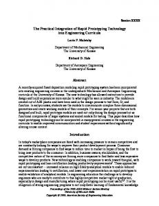
Combining MDE and Scrum on the Rapid Prototyping of Web Information Systems which proposed the Agile MDD. The literature of the area present several proposals for SDPs. Accordingly, the more intuitive and logical way to start a MDEbased software project is to select a specific approach and to follow its suggested activities. However, the industry present their own SDPs (Johnson et al., 2012). Therefore, it is important to consider the target SDP used by a candidate company for MDE adoption. Whittle et al. (2013) reasoned that instead of using a unique reference model to conduct a MDE-based process, demands from the industry present specific contexts, including the use of diverse SDPs and team skills. This influence adopted tools for design (Petre, 2013). This means that instead of using a common SDP and tools, some industrial contexts require the integration and adaptation of resources for MDE (tasks, tools and DSLs) into enterprise specific SDPs. Hebig and Bendraou (2014) claimed that studies in Software Engineering should evaluate the impact that introduction of MDE causes on reference process models in general. Based on these works, a software project conducted with a Scrumbased framework can impose threats to the introduction of MDE as well as MDE can impose threats to the software project execution. The literature of the area lacks information on benefits and difficulties that the combination of these approaches would add to the practice. MDE promotes modelling in all phases of a software development process (Kent, 2002). In the analysis phase, models are usually general and with no information that can lead to a technical solution. In the following phases, models are enriched with annotations containing details necessary to obtain the technical solution. These enriched models can be used to enable automatic generation of source code. This work stands on MDE as applied to the design of models for the domain of web information systems. These models are based on the architectural pattern Model View Controller (MVC) (Burke and Monson-Haefel, 2006) as illustrated in Figure 1. The design of models based on MVC requires the specification of several application layers through UML diagrams and/or web front ends. Models are used to generate prototypes, which in turn are used to help in requirements understanding and validation. In a Scrum-based SDP, Landre et al. (2007) recommend to execute cycles of feedback in which clients test a functionality under development in process iterations of short duration, named Sprints. Rivero et al. (2012) claimed that due to the time invested in design, the generation of prototypes through detailed models based on MVC can imply in delay of cycles of validation, which are executed in timescale larger than when prototypes are developed without MDE. This is reported as an issue to perform validations in agile software projects (Martin Fowler, 2005). Sprint cycles represent the number of repetitions to execute acceptance tests for the same functionality in the same Sprint. In order to support frequent feedback from clients, developers quickly apply changes in an increment
Figure 1
3
Multi-Layered Architecture Based on MVC.
of functionality until it is complete, using more than one cycle for validation (Schwaber, 2004). This suggests that in a Scrum-based software project and supported by techniques and tools of MDE it is important the use of an approach that allows iterative and incremental designs, following sequences of design, code generation, and validation in cycles of acceptance. Therefore, for the development context discussed in this work, the quick design of web front ends and associated MVC-based models is important. The next section motivates a case study applying our methodology and tool support in a software project conducted with the agile framework Scrum.
3 Motivation For some years, the first two authors of this paper have been in an effort to introduce model-based solutions in start-up contexts, developing several resources for MDE through their own company. This company was founded in 2007 and supported for three years by a business incubator hosted in one of the biggest scientific and technological areas in Brazil. Through this company we introduced MDE in some target software projects, three projects developed internally and other two externally (the first one failed and provided lessons for all the others). Only the last external software project is discussed in this paper, which is considered “MDE as Service” as illustrates Figure 2 box 2. In this scenario, resources developed for MDE (e.g., model transformations, DSLs and tools) are applied in different contexts. This is not easy and requires a set of techniques and reuse tools that make flexible the construction of resources for MDE. As discussed in (Basso et al., 2013), an analysis of the target context is carried out, highlighting which resources for MDE are used on the development of a specific software project, e.g., selecting an appropriate structure for MVC on the development of web information systems, as illustrates the dotted region in Figure 1. Resources for MDE are independent from the SDP reference model adopted by a company. It is in this scenario that our case study presents valuable lessons for the practice. An investor hired our enterprise to introduce our RAP methodology presented in Section 4 and its tool support, named MockupToME, in another start-up. His goal was to evaluate the feasibility and
4
F. P. Basso et al.
Figure 2
MDE as Service.
potential of our proposal when introduced in the context of “Company A”, which uses Scrum to manage software development projects (while in our enterprise we make use of AMDA). Taking into account this demand, a case study for MDE as Service was conducted as part of an industrial innovation project. This study was planned a year before introducing our approach in Company A, considering risks. Such innovation project has been supported by FINEP, a Brazilian governmental agency of support to research and development.
4 Review of Adopted MDE-Based RAP Approaches
Figure 3
In order to apply agility principles together with MDE in short iterations, the quick design of annotated models and the generation of testable prototypes must be considered. This is called Rapid Application Prototyping (RAP) and can be performed through several tools and techniques. This section discusses on RAP techniques that we have already applied in practice and introduces briefly the one that we have found to be the more suitable to an agile context. Such technique will be detailed in the next section. Along some years (Basso et al., 2007), we have experienced some RAP approaches for design and code generation on the development of web information systems as follows. First approach. The RAP approach illustrated in Figure 3 (1) makes use of detailed models designed with UML for requirement specification. In this approach, models are manually annotated with stereotypes and tags, providing semantics for business logic, web front ends and persistence logic. It requires experienced designers. A drawback of this approach is the big effort in design before executing the validation of a testable application piece. However, it is appropriate to represent details in a model organized in different MVC layers, enabling the generation of modular source code through a “model-to-code (M2C) Execution Engine” and resulting in a fully implemented prototype. Second approach. The approach for RAP illustrated in Figure 3 (2) allows to generate Mockups from a Conceptual Model (entity classes) through “Start templates”. This is a categorisation for a set of model
transformations used in initial phases of prototyping. Besides, a “M2C Execution Engine” enables the use of these Mockups to generate the application code (without Annotated MVC Models). This is similar to implementations of web frameworks such as Ruby on Rails. From our experiences, we have found that this is the easiest and quickest RAP approach because it do not require big effort in design. Code generated from Mockups enables clients to experiment and explore system functionalities, typically generated in a simple layout structure that does not change, such as templates for JSF using Java Facelets. A benefit of this approach is the quick validation of an application piece generated in conjunction with clients, while the previous approach requires more effort in modelling, implying in the validation carried out more lately. However, due to the limited expressiveness of Mockups, simpler prototypes than the ones of the first approach are generated, requiring several changes in source code to make them customized for the client. This effort is due to the lack of rich semantics associated with GUI components in Mockup designs (e.g., absence of semantics for business logic). Thus, the prototype design does not reflect the final code and can be discarded after the code generation. Third approach. The design approach illustrated in Figure 3 (3) includes a “Model Refinement Engine” named MockupToME and was proposed to speedup the specification of “Annotated MVC Models”. In
Approaches Adopted to Design Web Information System Models
Combining MDE and Scrum on the Rapid Prototyping of Web Information Systems
5
this approach, MVC models are generated through Mockups more detailed than those ones of the second approach, since they specify business logic through tags and stereotypes. This is an innovative approach that supports the generation of the application’s full source code through models refined in multilevels of abstraction by using a “model-to-model (M2M) Execution Engine”. Besides, the third approach combines the aforementioned ones through automated design techniques discussed in Basso et al. (2014a). This was the approach adopted by Company A in the case study presented in this paper and will be better detailed in the next section.
5 Our MDE-Based RAP Methodology Our more recent RAP approach is more complex than the previous approaches due to the use of two different abstraction levels for models and techniques to construct Mockups. Thereby, we have proposed a support methodology whose main tasks are shown in Figure 4. This work presents an overview of the proposed RAP methodology considering it as independent from any SDP reference model. A complete description of the MDE tasks is presented in Basso et al. (2014a). The proposed methodology supports three kinds of tasks: • Automatic and semi-automatic model-tomodel (M2M) transformations are applied to identify system requirements, domain and project classes, and types of user interactions with the system. Models are designed and refined from a high-level of abstraction (Mockup) to a MVC-based abstraction level. Automatic tasks are represented by a “script” icon (tasks 2, 4 and 6 in Figure 4) while semi-automatic tasks are represented by a “user” icon (task 3 in Figure 4). • Automatic model-to-code (M2C) transformations are applied in task 6, after Mockup designs are approved by clients. These transformations are responsible for generating the source code based on the MVC model layers shown in Figure 1 (view, business logic and controller). • Manual tasks are represented by a “hand” icon and can be required to complement fragments of source code that need to be manually refined by software engineers after the execution of task 6. Also, new design elements in UML models, whose semantics is not possible to be automatically added through Mockup refinements supported by tool, can be needed in task 5.
5.1 Lifecycle We have used BPMN (BPMN, 2014) to model the RAP lifecycle of our methodology as shows Figure 4. In this model, BPMN lanes represent stages of design
Figure 4
Overview of our RAP Methodology to Generate an Adapted MVC Architecture.
and refinement in the RAP lifecycle. In each stage different input and output data are used for the model transformations shown in Figure 3. Bellow we depict each stage of the proposed methodology. Agile analysis. In this stage three methodology’s essential artifacts are produced: “Sketch”, “User Story” and “Conceptual Model”. A sketch is a drawing in paper representing GUI components and screen flows and a use story describes intentions of users to accomplish a specific functionality. From these artifacts, an Analyst can specify a conceptual model, which is a set of classes describing the entities whose data/objects will be persisted into a database (also called as analysis classes) shown in the top of Figure 5. This is the minimum set of artifacts to start the RAP approach. However, one can use other representations for requirements such as textual use cases represented with a DSL, glossary, supplementary and non-functional requirements (e.g., representing the periodicity of calls for methods of some classes).
6
F. P. Basso et al.
Evolutionary prototyping. This second stage of the methodology is supported by automatic and semiautomatic M2M transformations. The first task related with MDE is, therefore, executed after the “Agile Analysis” phase, when Mockups are generated in task 2 and refined in task 3. In task 2 the designer consider a “Sketch” that describes a functionality from the viewpoint of analysis to generate a preliminary Mockup through a specific model transformation template, illustrated on the middle and bottom of Figure 5. Each Mockup model is in conformance with the MockupToME metamodel presented in (Basso et al., 2012), which is a DSL in higher-level of abstraction than the UML. Teams can design Mockups with different implementation structures from those drawn in a Sketch, suggesting different options to clients that could better satisfy their needs. Options to structure a Mockup are generated automatically through homogeneous M2M transformations (based on the same metamodel). Clients opine about the Mockup design, resulting in an “Accepted Mockup Model”. Therefore, an accepted Mockup is not a rigid layout structure based on a specific GUI template (which is the result of task 2). It is a customized design built in a creative process represented by the task “Refine Mockup”. Architectural prototyping. After a Mockup is accepted by the Client in task 3, Mockup components are used to generate the “Annotated MVC Model” in task 4, which are model pieces of the MVC architectural pattern. Thereby, the phase “Architectural Prototyping” aims at transforming a high-level model (annotated Mockup shown in Figure 6) to implementation-level models with the MVC-based structure shown in Figure 8. Each generated model can be manually refined in task 5, adding more semantics for elements through tags and stereotypes from the UML Profiles discussed in the Section 5.2. Functional prototyping. The last phase of RAP is named “Functional Prototyping” and aims at detailing a generated prototype along cycles of acceptance to then perform acceptance tests. An “Annotated MVC Model” is used as input for M2C transformations that generate a working prototype in task 6. This prototype will be target of developer tests. This is the point in which Clients interact with a compiled application running in a web browser/application server. Finally, after task 7 a working software piece is delivered as a fully implemented functionality and then acceptance tests are executed.
Figure 5
Generation of a Mockup With the MockupToME Tool
Figure 6
Accepted Mockup Model: Screenshot of a Mockup to Maintain Categories From the System “P&D.NET”
5.2 Tool Support This section exemplifies our tool support for the proposed methodology. Running example. The running example considers a functionality from the system “P&D.NET”which was developed in the case study presented in this paper. A screenshot of this system is shown in Figure 7. The system is focused on the management of financial
support, considering Brazilian laws to foment innovation projects. On the left side of Figure 7 is shown a menu of functionalities manually developed by the project team of Company A. On the middle of Figure 7 is shown a web front end generated by our proposal for RAP. This front end is part of a functionality of type CRUD (Create, Read, Update, Delete) that aims at implementing actions to persist and retrieve information
Combining MDE and Scrum on the Rapid Prototyping of Web Information Systems
Figure 7
Screenshot of a Functionality from System “P&D.NET”.
shown in this web form into/from a database. This information is organized in entity classes, selected from the “Conceptual Model” to implement a “User Story” as illustrates Figure 5 (1). The Conceptual Model from the system “P&D.NET” contains entities such as “Project”, “Product” and “FinancialSupport”, associated with a category. In the following we exemplify the application of the tool support on the development of the user story “Develop the maintenance of categories of financial projects”. MockupToME tool is used to represent the first abstraction level of models. In our tool support for RAP, named MockupToME, the application design starts by generating a “Preliminary Mockup Model” from an input “Conceptual Model” as illustrates Figure 5. It provides a set of menu items representing “Start Templates” (see Figure 5 part 2) that generate mockups with action semantics for persistence. These menu items are used to design the User Story “Develop the maintenance of categories of financial projects” of our running example. The Designer must select a “Start Template” from a popup menu (Figure 5 part 2) to generate a Mockup for the entity “Category”. These templates are available in popup-menus, dynamic model transformations and model transformation wizards (see Basso et al. (2013)). The generated Mockup shown in Figure 5 (3) is then enriched by the designer with annotations representing the application’s business logic. This procedure is carried out through the “Model Refinement Engine” provided by the MockupToME. The refinement of such a Mockup is performed by the designer through the generation of common structures for web front ends, shown on the right part of Figure 6, in an evolutionary prototyping approach.
7
Annotations in Mockups. The left side of Figure 6 shows an element tree with two annotations associated with the titled panel “Category Filter”, which is graphically shown in the right part of this figure. The annotation maps this panel to an “HTML Form Tag” and indicates this panel will handle end-user interactions related to filtering of data associated with the class “Category” of the “Conceptual Model”. The “Model Refinement Engine” uses these annotations to build the Mockup, e.g., linking actions related to “Filter” with the panel “Category Filter” according to its associated annotation . Buttons of Mockup are also automatically created with “Start Templates”. Icons of buttons vary according to the annotation assigned to them in the drawing area. For example, the left side of Figure 5 shows the stereotype , which is associated with the button named “Save” shown in Figure 6. Similarly, is associated with the button named “Search”. These annotations are automatically added by the MockupToME tool while the designer applies refinements on the model through menu items (see the demonstration video of design and refinement of a more complex Mockup in http://prisma.cos.ufrj.br/wct/ projects/mockuptome home.html). UML Profiles are used to represent the second abstraction level of models. MVC-based models are represented with four UML Profiles: a) The GUI Profile (Blankenhorn, 2004) is used to represent GUI components (view layer) since UML has no diagram to draw GUIs; b) The Action Profile is used to represent GUI component actions (controller layer) as a UML activity diagram; c) The Service Profile enables to define details about the business logic layer for services that implement the classes Remote, Validation and Data Access Object (DAO); d) the ORM Profile is used to apply object-relational mappings on the model layer. Abstraction layers of the “Annotated MVC Model”. Automatic M2M Transformations use the “Accepted Mockup Model” to generate the “Annotated MVC Model”. Figure 8 (1) shows another abstraction level for the View Layer in which a model is represented using our “GUI Profile”. GUI components of this profile are more appropriate for designers to provide details in web layouts than the DSL used to represent Mockups. Figure 8 (2) shows an UML interface representing operations and parameters annotated with the “Service Profile”. This profile allows the representation of business logic associated with events of buttons represented in a Mockup. Figure 8 (3) shows the controller layer represented with the “Action Profile”, a UML interface with operations to control events and flows. In (Basso et al., 2012) we discussed on a set of heterogeneous M2M transformations applied in this stage that convert a Mockup specification based on the MockupToME metamodel (see http://prisma.cos.ufrj.br/wct/projects
8
F. P. Basso et al.
Figure 8
Annotated MVC: Layers (View, Business Logic and Controller) Generated From the “Accepted Mockup Model”
/mockuptome metamodels.html) to specifications based on the MVC. The FOMDA approach is used to generate the source code of application. Resources for MDE (e. g., code generators) enable the transformation of the “Annotated MVC Model” shown in Figure 8 into code mapped for several application layers shown in Figure 1. These layers are flexible to support specific implementation APIs for the Java J2EE architecture. Some layers are used only in some the target software projects. For example, the Remote layer is only necessary when a desktop or mobile view is necessary, which is not the case for this study. This flexibility in code generators needs appropriate tool support to adapt model transformation resources for specific needs from software projects. The FOMDA approach is used to develop flexible and adaptive model transformation components, as depicted in (Basso et al., 2013). This approach is assisted by the tool support named FOMDA Plug-in, not presented in this piece of work, used by a Java Senior architect, who defined how models are transformed from Mockups to the underlying MVCbased architecture and code.
6 Case Study Combining MDE and Scrum We present a case study on the introduction of an MDEbased RAP approach in an agile software development project, enabling the use of iterative and incremental development. As a result of the context analysis of the target company we proposed essential model-based tasks and free of conflict with agile principles associated with
Scrum. This experience demanded financial investment and consumed more than a year of work before starting the execution of the software project. The case study included an analysis of context, the planning of the combination of MDE and Scrum, and adjustments in tool support. The next sections contextualize this study.
6.1 Case Study Format The case study is focused on the introduction of our RAP tool MockupToME in Company A, which uses Scrum to manage software development projects. In the following we present the format of this study. Goal: To observe how MockupToME contributed/affected the development of a web information system built from scratch considering the context of Company A. General context of the software project: The software development project involved two Brazilian software companies, which in this paper are denominated “Company A” and “Company B”. These companies collaborated to develop a web information system for management of innovation projects. Such system is divided in two subsystems: Company A used our proposed RAP approach to develop the subsystem named “P&D.NET” shown in Figure 7 while Company B developed the other subsystem named “SAGLI” without using MockupToME. The development ran independently each other resulting in two subsystems, integrated at the end of the project though Java web services. Case study configuration: This is a primary study, in vivo, focused on the introduction of our RAP approach in the context of Company A, evaluating benefits and
Combining MDE and Scrum on the Rapid Prototyping of Web Information Systems drawbacks promoted by the approach on development of the system “P&D.NET”. Along five months we observed the development of the subsystem “P&D.NET” carried out by Company A. We monitored the effort of the team to produce a testable application piece. The project team from Company A used our RAP approach with Scrum and has been composed by: a Scrum Master, a Java developer, a Tester, and a Designer. To programming, the team used a trainee developer, which means he needed a learning period to assimilate the technology after two weeks of training. Evaluation format: Due to differences between the subsystems developed by Company A and Company B and differences in implementation APIs for the View layer (Company A used JSP whereas Company B used JSF), it was not possible to conduct a controlled experiment. Instead, we conducted an observational study on the software development in Company A. Thus, from empirical viewpoint, the evaluation of our proposal is based on a case study, which is not controlled by researchers and therefore provides more imprecise results than an experiment. This is the reason why our study did not allow us to obtain more conclusions than lessons learnt. Lessons learnt are presented in Section 7. On the other hand, the case study was important to the practice associated with MDE. Such study provided us new insights and challenges regarding MDE as Service that are presented in Section 8. Feedbacks. The project team from Company A provided us qualitative feedback every week, allowing us to observe issues related to the development of prototypes and its impact on the duration of a Sprint. We have not collected other quantitative measures, except on the size of the produced subsystem in Company A. We have collected qualitative attributes from Company A such as on usability of the MockupToME tool, required improvements, and bugs.
6.2 Introducing our Methodology In a Scrum-Based Software Project So far, our methodology has been presented of agnostic way to the context of Company A, i.e., independently from a process reference model or software project. This section reports our experience in introducing the methodology in the context of Company A through some essential tasks recommend by the Software Engineering discipline. Analyse the adopted process reference model or similar processes found in the literature of the area. An analysis of target context was carried out some months before the execution of the software project. Through this analysis, we identified activities related to MDE that should be performed before, during and after each Sprint. The SDP research suggests that the combination between a methodology and a process can be facilitated through techniques for Method Engineering, Process Lines and Tailoring (Pillat et al., 2015). However, we have not considered these techniques
9
because Company A has not a defined process. In the lack of a baseline to understand and adapt the adopted Scrum-based process, we studied this software development framework through documents, books and trainings. Conduct preliminary feasibility analysis. To understand if some tasks of MDE are feasible for the target context, we have conducted a preliminary analysis through ad-hoc tests, evaluating the use of the RAP methodology in toy examples. We have considered the time scale for Sprints suggested by Company A (seven days) and its team configuration, which would use one inexperienced designer and one inexperienced developer. In this regard, our main concern was that the execution of a Sprint with our RAP methodology could be compromised because the need of highly detailed models. Thus, ad-hoc feasibility tests helped us to define tasks of MDE to be performed in short timescales. Introduce RAP tasks within the target software process. Due to the lack of a defined process reference model to use with the proposed RAP methodology, our best option was to find in the literature a Scrum methodology that is closer to the practices used by Company A. Thus, we used the “Scrum methodology” (Schwaber, 1995) as a guideline to organize MDE-based tasks in three distinct phases: “PreGame”, “Game” and “Post-Game”. The Pre-game and Post-Game phases can be pre-determined in a process reference model while the game phase is dynamic. In the following we present tasks that we considered as additions to the Scrum methodology shown in Figure 9. Also, we present guidelines to introduce the RAP methodology within a Scrum-based software project.
6.2.1 The Pre-game Phase The Pre-Game phase conducted by Company A included typical activities of planning of the Product Backlog, team planning, analysis of risks, estimation of release cost and funding. Moreover, bellow we present additions to the pre-game phase, which groups preliminary decisions to the execution of the software project. Prepare MDE resources to the context of Company A. We configured model transformation assets to be used in all the Sprints using the FOMDA approach. More information about how to specify and adapt resources for MDE can be found in (Basso et al., 2007, 2013). Ensure team’s commitment with the adoption of MDE. A software project that includes MDE aims at the future reuse of models, otherwise it should not be used. In this sense, it is important to make clear for the project team the change of paradigm. From one side, MDE practices are focused on reuse, meaning that the designed model is the most important artifact produced in a software process. From other side, agility principles demand focus on producing testable application pieces, meaning that the application itself is the most important part and not the artifact used
10
Figure 9
F. P. Basso et al.
Introduction of the Proposed RAP Methodology Within the Scrum’s Game Phase
to build it. A meeting to discuss expectations regarding reuse of models was conducted, ensuring the team’s commitment in performing tasks for MDE. Integrate the adopted analysis approach with the RAP methodology. We have developed a DSL to represent textual use cases as models. However, Company A adopted a simple analysis approach using Sketch and User Story to find requirements. In this case, we discarded the DSL for textual use cases and integrated the agile analysis used in Company A into the methodology. Thus, we planned and discussed with the company’s team how to move from agile analysis to RAP. Expose to the team the changes that will be introduced with the new methodology. In addition to the agile analysis conducted in Company A, we recommended the design of a conceptual model in order to satisfy the required input by our RAP methodology and MockupToME tool support. The incorrect design of this model would imply in problems in the generation of Mockups and repetition of tasks to adjust the design. Thus, we introduced recommendations to generate correctly a “Preliminary Mockup Model” in task 2 of our methodology pointing out the differences between Scrum and MDE. Define and expose to the team the expected time interval for the high-level and architectural design in Sprints. Before the definition of a Sprint, it is important to agree with the team on the interval of time that will be used by designers before developers start the implementation of the system. For example, if a goal in Company A is to obtain more expressive code generation in future reuse of the designed models, then more hours should be allocated in Sprints to include manual tasks that enrich the design or models of other abstraction levels designed with DSLs. Company A opted to invest at most 16 hours on design tasks in each Sprint, what limited the application of some manual tasks. For example, the refinement of the “Annotated MVC Model” during the “Architectural Prototyping” phase could not be applied in a so short timescale. Define if and which manual design tasks are performed in Sprints. Manual design tasks can be performed to enrich models, as long as they
do not compromise the timescale of Sprints. The execution of simple manual tasks on UML models in the “Architectural Prototyping” phase, e.g., to adjust the name of parameters from operations in the “Annotated MVC Model”, is not a problem for the timescale of 16 hours for design. However, we have found in our ad-hoc tests that manual tasks for reverse round-trip engineering (from code to model) demand from the team much expertise and, consequently, need more than 16 hours for design tasks. Therefore, we recommended Company A to not carry out manual design tasks such as round-trip inside the Game phase for two reasons: 1) to have more time in Sprints for developers to use in the “Functional Prototyping” phase; and 2) to reduce information overload for inexperienced designers.
6.2.2 The Game Phase As illustrates the central-part of Figure 9, the proposed RAP methodology is applied inside Sprints in the Game Phase. As requested by Company A, we planned MDE tasks to be executed in short duration Sprints, using seven days of work. Considering this timescale for the complete execution of a Sprint, we picked the concepts discussed in Scrum methodology’ phases named Architecture and High Level Design and Development and organized our RAP methodology in conformity these phases as follows. Execute Sprint Planning according to the RAP approach. The Sprint planning includes a RAP planning. In the Sprint planning we recommended the team to discuss on user stories and design issues to then define a development schedule. In order to include our RAP approach in the planning, we recommended the team in Company A to discuss the applicability of existing transformation templates to generate Mockups. Thus, development tasks were classified according to some categories of transformation templates in each Sprint Planning. Define the time scale of initial Sprints. Due to the use of inexperienced team’s members, we helped Company A to define Sprints in the first two moths and let the team to define them in the following months as its members became more familiar with the RAP methodology. Ideally, based on its experience and on
Combining MDE and Scrum on the Rapid Prototyping of Web Information Systems metrics from other projects, the team should be able to define the duration of a Sprint using information from the RAP planning. However, because this was the first project conducted in Company A using a RAP approach, no metric or previous knowledge from the team could be used to suggest a schedule. Characterize functionalities based on available model transformation templates. System functionalities are firstly characterized as specific structures for Mockups described by a “Functionality Type”, as illustrated on the middle of Figure 9. Types of functionality currently supported in MockupToME include the generation of Mockups following structures for web front ends (e.g., CRUD, filter/search), structures for reports and for data interchange with spreadsheets. The characterization dictates if it is possible to use our RAP methodology to generate a preliminary Mockup or if the functionality must be developed without support of model transformations. From user stories and sketchs of the pre-game phase, the team specifies a Sprint Backlog highlighting how the tasks named “Generate Preliminary Mockup” and “Refine Mockup” will be executed. The planning starts with the choice of which model transformation templates, called “start templates”, will be used to initiate the design of a Mockup. The structure of a Mockup is discussed between team’s members, highlighting “refinements strategies” that could be applied in the task “Refine Mockup”. Map conceptual model elements for start templates in the Sprint planning meeting. Based on the characterization of a functionality, Developers map which model elements (classes from the conceptual model) will be used as input for “start templates”. Activities a software engineer has to follow when generating mockups are: to find domain classes from the conceptual model that are related to a same functionality (i.e., they are described in a same user story), and then to use these classes as input for a start template. Use iterative and incremental steps following the RAP methodology. The design and refinement of Mockup in the third task shown in Figure 4 is a creative process of discovery and invention, which needs constant feedback from Clients. We inserted the task “Refine Mockup” inside the phase “Discovery and Invention” of the Scrum methodology. To support quick feedback from Clients, a Mockup must be designed in hours, not days, considering strictly requirements of an unique Sprint. In following Sprints, a previously designed Mockup can be modified when requirements from a new functionality are introduced. This is not a big issue because the code and lower levels of models are (re-)generated by the tool support. Therefore, a team will make use of all the RAP tasks in iterative and incremental steps of discovery, invention, implementation and test. Obtain clients’ feedback before the implementation. The validation of Mockups aims at reducing rework in development, a benefit associated with prototypes. However, such benefit implies at least one cycle of feedback from Clients to validate the
11
Mockup before the code implementation. Semantics associated with components of Mockup allows designers to demonstrate flows of GUIs inside the MockupToME tool. It is also possible to demonstrate GUIs and flows in a web browser. Apply corrections on the generated code to execute automated test cases and acceptance tests. Models shown in Figure 8, generated from the “Architectural Prototyping”, are input for code generators of test cases. These tests persist and research information associated with conceptual models and Mockups. Full source code is generated for all the application’s layers except for automated test cases. Developers need to complete test cases by adjusting values of properties from entity classes (the “Model” layer). These classes are annotated with specifications from the Object Relational Mapping (ORM) Profile, allowing the execution of operations to persist and retrieve information to/from a database. In order to test these operations, each test case uses instances of classes derived from the UML Service Interface shown in Figure 8 (2): “Remote” (when is necessary GUIs for Desktop or Mobile), “Validation” that validates properties from entities, and “Data Access Object” that implements business logic with a query language (e.g., SQL or HQL). A test operation is generated for each action represented in a Mockup (e.g., for the button Save). Monitor, report and plan changes. Changes can be simple adjusts in models or complete modifications in requirements. When adjustments are needed in the first cycle of Mockup’s validation, designers can apply the corrections in the model and follow to the Architectural prototyping stage. We suggested that all changes in Mockups should also be applied in user stories as soon as the client validates the design and suggests alterations. In the second case, when changes in requirements are needed, we recommended to plan such changes in an activity apart from the main process. For example, in Figure 4 the change planning is started from the event “Start Change Management”. This event represents the need of a new meeting to discuss when these changes must be handled: in the current Sprint or in a next Sprint. Our case study did not present radical changes such as rejection of the designed Mockup, but they occur, such changes should be thrown away and the RAP methodology should be applied again for the new requirements.
6.2.3 The Post-Game Phase Manual development of source code may require roundtrip engineering, a counter agile practice. Our adhoc tests pointed out that tasks for round-trip, which must manually revert code for models, hampered the execution of short iterations. The inexperience of the designer and developer is a problem to perform reverse round-trip engineering when these stakeholders must revert details from code to model. On the other hand,
12
F. P. Basso et al.
the generation of code from model is automatic, meaning that such an inexperience is not problem to apply this MDE task. Thus, we recommended that reverse roundtrip engineering, if necessary, must be applied in the “Closure” phase of the Scrum methodology or at the end of the software project. In our case study, Company A did not need to apply reverse round-trip engineering.
6.3 Synthesis of Results After five months, the case study’s project resulted in the specification of 47 domain classes and 22 core mockups. These mockups were automatically generated as CRUD/List forms through our “start templates”. All developed CRUD functionalities involved associations between entity classes. This means that mockup refinement strategies provided by the MockupToME tool were used for the design of these functionalities. Such strategies are based on the design technique known as master-detail (Molina et al., 2002) and were previously presented in (Basso et al., 2014a). Designed mockups led to generation of 82% of overall functionalities, divided in: a) 22 classes for controller layer; b) 35 classes to support the data access layer with fully embedded business logic; c) 35 classes for form validation; d) 47 domain classes with ORM annotations; e) 56 JSPs to support the view layer (some UI screens were generated in more than one file). Although the number of days required to complete a sprint (i.e., the development of a complete functionality) decreased along the project, the generated code by our tool support needed of some manual modifications until that the full code was generated in last three Sprints, not requiring adjustments. From the case study, we can state the proposed methodology was successfully applied for the development of an application started from scratch in a Scrum-based software project. Since the software production using our proposal is focused on delivering working application pieces in each Sprint, the introduction of our MDE-based tool in preliminary software process phases did not conflict with agile principles. Therefore, all the practices suggested in the Scrum methodology could still be applied.
6.4 Qualitative Evaluation from the Company At the end of the case study, we talked to three leaders of the software project (the Investor, the Scrum Master and the Product Manager) in order to obtain feedback about the experience. Concerning benefits and drawbacks of using our methodology and tool support, company’s leaders did not realize any benefit regarding agility in the system development. However, they also did not identify production delays related to the use of our approach after the team’s learning phase. Moreover, they reported that there was no change motivated by missing or misunderstood requirements between sprint cycles. They
considered this a benefit of the proposed methodology and tool, promoted in preliminary development phases. Company’s leaders also reported the following benefits: i) better source code organisation and modularisation when compared with their previous practices; ii) ease to change the generated source code; and iii) simple and rapid design of mockup models. In addition, they expected to obtain future benefits promoted by the reuse of designed models. As a last consideration, company’s leaders reported that would be beneficial if model transformation tasks could be used inside Eclipse workspace instead of in processes started by menus in MockupToME. Recently, they requested us an integration with the Mylyn plugin in order to manage MDE and development tasks in the same environment. They believe this integration could contribute to reduce the learning curve of developers.
7 Lessons Learnt from the Case Study Bellow we point out some lessons learnt from our experience in introducing a MDE-based RAP approach to an agile software development project. Learning Curve. Initial Sprints of the software projects typically require longer time (days) in first weeks, because the team is still unfamiliar with the problem domain and development tools (Shore and Warden, 2008). In this sense, techniques and tools introduced by our methodology increased the time necessary for the project team to surpass the learning period. In the case study, we have provided a tutorial and daily mentoring meetings for one month until the developer of Company A gain autonomy in the use of our methodology and its tool support. Thus, due to the required training period to understand and apply our proposal, the project team started producing indeed after one month. However, MockupToME was not the reason for the long learning curve, since models were designed correctly and with little difficulty since the first week. Instead, the Java Architecture provided for the development team hampered the introduction of our proposal since the project’s developer had no experience with the programming language Java and there was no other technical staff that could provide active assistance. Observations from the case study suggest that the presence of senior developers in the developers group of the target company (not necessarily in the same agile team) is fundamental to reduce the learning curve concerning the proposed methodology, software development architecture and tool support. Thus, future work will explore this proposal using inexperienced developers that have access to senior developers of the company. Team’s Experience Level. The developer that designed application functionalities using our tool support did not have previous experience in design of
Combining MDE and Scrum on the Rapid Prototyping of Web Information Systems prototypes. Nevertheless, he faced little difficulty in using MockupToME since first iterations of the project. This allows us to state that our proposal can be used by small teams, when only non experienced designers (or developers) are available to perform MDE-based tasks. However, we acknowledge that the learning curve related to the provided software development architecture needs to be reduced to allow better results in practice. Extent of the Code Generation. Designed mockups led to the generation of 82% of the system “P&D.NET”. Since some transformations did not generate full code, some changes were necessary in the view layer. However, no change was motivated by misunderstanding requirements. All changes were related to small code pieces that were not completely generated. The need of completing the generated code was identified as an issue, fixed along Sprints by us. To address it, we believe it is necessary a richer set of transformation strategies (start and refinement templates), which demands investment on development of model transformations. Change Management. Our approach for RAP allowed the project team to perform two cycles of feedback with clients in iterative and incremental development. Concerning CRUD functionalities, changes in requirements do not imply in round-trip engineering since source code is generated again along iterations. This is possible because annotated models contain many details related to action semantics, which are necessary to generate code of CRUD functionalities. Such detailed information regarding action semantics enables the generation of executable application pieces without the need of developers to apply changes in related modules of the source code. Through this approach, prototypes are central artifacts to allow clients to validate functionalities before and after the source code generation. Therefore, chances in requirements can occur in all the phases of the development process, figuring as an important contribution of our approach to support iterative and incremental development steps. Abstraction Levels for Application Models. A higher-level of abstraction than UML was essential to support short development iterations in the context of the case study. The software project of the case study adopted short iterations of one week. Thus, in order to fit for a context of agile project, it was necessary to speed-up the design of models, improving the design tool MockupToME with new functionalities. This tool obtained positive results in the design of prototypes, abstracting the representation level of requirements from a UML MVC-based design to a Mockup-based design that is more simple and intuitive. Accordingly, our methodology and tool support prevent long sprints/iterations through two design languages, one for quick generation of annotated Mockups and other to detail MVC-based application layers using the UML. Adaptation of MDE resources for the target context. It is important to consider project team’s skills to decide on which tasks and tools of MDE
13
to include in an enterprise specific software process. We have focused on the agile principle that states “Deliver working software frequently, from a couple of weeks to a couple of months, with a preference to the shorter timescale” (Kent Beck et al., 2001) while adapting tools and tasks for the context of Company A. From the case study, we have found that: 1) For the combination of MDE and Scrum to be effective, an appropriate RAP strategy should be adopted considering the team experience; 2) Simple and quick design of models (Mockups and MVC models) is essential to project teams composed by inexperienced designers.
8 Issues for Future Research The literature of the area lacks information on how to introduce MDE in specific contexts. Although many works are essential to understand threats that involve MDE adoption (Hutchinson et al., 2011; Whittle et al., 2013; Petre, 2013), they only present a superficial analysis of the problems. A limitation of these studies is the lack of focus on specific application domain, such as web information systems or embedded systems. The quick development of prototypes could be useful in these domains. Thus, in order to better understand issues that hamper MDE adoption in industry, empirical studies should be directed for specific contexts. Which are the suitable MDE techniques for dealing with round-trip? It is known that regarding agile methods, changes in requirements should be well received. However, little is known about suitable techniques to apply changes on software artifacts with tool support for round-trip engineering along the SDP. Thus, the Software Engineering research could contribute with future studies on what is “good” or “bad” in this regard. Some authors claim UML-based RAP approaches are “counter agility”, but are they really? Fowler presents two important questions in this regard: “Can you get a design that is capable of turning the coding into a predictable construction activity? And if so, is cost of doing this sufficiently small to make this approach worthwhile?” (Martin Fowler, 2005). These questions are not answered in this paper and should be explored by the academy. The author claims that the use of UML to predict and validate requirements with clients is inefficient in practice due to frequent changes on requirements. Therefore, he answered the two above questions with a “no”. On the other hand, other researchers have been using the UML as front end to combine MDE and agility (Kruchten, 2010), suggesting that the answer for the aforementioned questions would be “yes”, since they have found positive results in practice. Therefore, issues should be evaluated and answered empirically. The “good” and “bad” on the combination of MDE and Agile should be associated with a context. For example, we believe that in the context of
14
F. P. Basso et al.
Company A it would be impossible to use UML directly as front end in iterations of one week, in conformance with (Martin Fowler, 2005). We have attempted to use UML in previous software projects with short iterations and have not succeeded in these experiences. However, in another company we have used UML with iterations of four weeks and have achieved good results developing complete systems with an expert designer. In our view, answers for questions like the above ones cannot be generalized to all companies, processes and team configurations. To be valuable for the Software Engineering practice, they have to be answered for each specific context (e.g., big, small or start-up companies, teams with different configurations, etc). Accordingly, we have reported in our previous contributions (Basso et al., 2007, 2012, 2013) the importance of target context for choosing a suitable DSL to start the MDEbased process. Therefore, instead of making general assumptions on the applicability of a reference model for SDP, methodologies and tools, Software Engineers should direct their observations for specific contexts. There is no requirement for “agile tools”. Which design tools are more suitable for agile teams? In which contexts? With which goals? These questions should be explored in empirical studies conducted in industry. The literature presents several proposals for MDE and RAP, but no criteria that could help Software Engineers to choose the best option for agile contexts is provided. This limitation makes very difficult to match the theory related to Agile Methods and MDE with practice needs of industry. As a result of the lack of requirements for agile tools, the decision on which tools and tasks to include in a defined process for a target company is still ad-hoc. There is no empirical information in the literature on incompatibilities between MDE and Agile Methods/Principles. The subjectivity of the information available in the literature of the area makes very hard to understand if a modelbased task is incompatible with agility principles. Most of information that we have found related to Agile principles resembles general recommendations of software development, which is not useful for one who needs to use existing MDE resources in the context of a Scrum-based software project. Several assumptions have to be defined, which is a difficult decision for the service provider, since no one knows exactly how to deal with these approaches together. We have invested big effort to understand incompatibilities between MDE and Scrum and at the end of our analysis we have realized that the unique relevant issue to combination of these approaches is the need of Sprints with short timescale. Thus, due to the lack of theoretical and empirical information on incompatibilities between Scrum and MDE, we have conducted a case study that evaluated the combination of these approaches in practice. Other studies evaluating such combination are necessary to understand this software development scenario.
9 Related Work Scrum and MDE: Our RAP methodology suggests to plan MDE-based tasks in each Sprint. This is also a recommended practice by the agile method called Feature Driven Development (FDD) (Chowdhury and Huda, 2011), which includes a general guideline to perform model-based tasks. Our position is that one do not need a new SDP to include the planning of MDE tasks. Such planning can be included within the SDP used by the target company through process adaptation. Thus, instead of proposing a new SDP, we focused on the introduction of MDE tasks within an existing SDP. In addition to the Scrum methodology (Schwaber, 1995), we included tasks for design considering two abstraction levels for models. We divided the Scrum phase Architecture and High Level Design in three RAP phases (Evolutionary Prototyping, Architectural Prototyping, and Functional Prototyping), which help to make the transition from the design to the Development phase. Kulkarni et al. (2011) proposed recently a new SDP that combines Scrum and MDE, arguing that a pure agile methodology does not work with MDE. To the design and validation of models, authors proposed the use of Meta-Sprints that run in parallel to Sprints. This proposal seems strange because in agile methods Clients must provide feedback on models and/or prototypes in shorter timescales than 2-3 months, which is the time suggested by authors for Meta-Sprints. Our analysis of Scrum and from the case study suggests the opposite: One can use this agile framework in timescales of 12 weeks, including design tasks in a Sprint, without the need of Meta-Sprints. In our approach, tasks of model construction and implementation are sequentially performed inside each Sprint, which means they are not parallel but interrelated in three RAP phases. For this reason, introduction of Meta-Sprints in Scrum seems us more a “waterfall” lifecycle than an iterative and incremental one. Therefore, we used Scrum as it is defined in (Schwaber, 1995). FDD (Chowdhury and Huda, 2011), AMDA (Ambler, 2015) and Meta-Sprint (Kulkarni et al., 2011) are general SDPs that propose the combination of Agile and MDE. A limitation of these works is the lack of definition concerning which DSLs and tools can be successfully used in a target context. Differently, we defined “where” and “how” to apply “what” within the Scrum methodology. Zhang and Patel (2011) claim that such definition is critical to understand benefits and drawbacks of approaches that introduce MDE in agile contexts. Authors proposed the Agile MDD approach and validated it through an industrial case study on the development of real-time system. Although the approaches were applied in different domains, authors drew similar conclusions to ours and also discussed issues related to learning curve. Agile MDD is a Scrum extension, suggesting new concepts such as Test Driven Modelling and Continuous Modelling. These
Combining MDE and Scrum on the Rapid Prototyping of Web Information Systems concepts are also embedded in our tool support, but we decided to keep the conventional concepts described in the literature of the area. Differences between the approaches are: 1) Our approach is strictly applicable for the development of web information systems; 2) We used inexperienced designers in a start-up company while (Zhang and Patel, 2011) applied their approach in a more mature company with qualified designers; 3) Authors used only the UML to represent models in Sprints of 4-5 weeks whereas we used two DSLs and several UML Profiles for design in Sprints of 1-2 weeks. Different positions on the understanding and use of Scrum with MDE suggest that the definition of an instance for this SDP is very dependent from the context where MDE is applied, from the application domain, and from the availability of tools and DSLs to the domain. In this regard, our work is singular because it presents a report about introduction of MDE in a real target context that uses Scrum as process framework, adapting tools and tasks for use in the target context. This way, we did not propose a new SDP, but adapted Scrum to the target company. Different companies use different SDPs, with different team configurations, with individual skills that may need different tools to perform iterations in short timescales. Therefore, since everything must be flexible to be introduced in diverse target contexts, the reported experience in MDE as Service provided important insights for the Process Engineering research, with several open questions that deserve future investigation. Model-Driven Web Engineering: Our methodology for RAP differs from traditional UML-based design approaches, such as those ones proposed by Beigbeder and Castro (2004); Nunes and Schwabe (2006); Distante et al. (2007); Souza et al. (2007). These authors proposed the refinement of platform-independent models (such as annotated class diagrams, use cases, collaboration diagrams, and activity diagrams) to platform-specific models in a software development process based on MDE. We proposed the use of a higher abstraction level language to represent Mockups, which are further transformed for other models in lower abstraction levels (MVCbased models). We start our RAP approach from simple Mockups, which can be quickly generated and refined to then generate multi-layered models for web information systems similar to the ones designed with the aforementioned approaches. These proposals apply top-down approaches to design web information systems, in which input models, such as conceptual models, are highly detailed before generating a testable prototype. Some proposals focus on quick prototyping as a way to promote software reuse compliant to MDE and agility principles. Rivero et al. (2012) propose to add annotations to Mockups in order to generate business logic. Such annotations, for example, allow specifying action semantics to buttons and are used as input for transformations that generate models or source code for the persistence layer. Our proposal intends to
15
apply RAP, MDE and agile practices together through simple architectural models called Mockups. However, differently from (Rivero et al., 2012), our proposal uses other abstraction level for models based on the UML. Similarly, Grigera et al. (2012) generate MVC models in which View and Controller layers are generated through annotated Mockups. Although both proposals allow designing Mockup models, they are not aimed to be used in the whole software development process. Unlike these proposal, we use Mockup models as input to generate not only View and Controller layers, but others, such as business logic, data access object, entity/field validation, and remote/web services. In order to visualise and modify prototypes, Molina et al. (2012) propose the tool CIAT-GUI that allows to test information system models in different abstraction layers, generating intermediate models to detail business logic layers. However, the authors did not consider the use of a simpler abstraction level for GUIs (i.e., annotated Mockups) in the beginning of the RAP approach as our work did. Therefore, our contribution is important to help in the introduction of RAP through MDE in contexts whose developers are trainees (startups), while the manual design in the CIAT-GUI tool suggests that it needs experienced designers to represent models.
10 Conclusions and Future Work This paper has presented a methodology of Rapid Application Prototyping (RAP) based on MDE specially designed for use in agile software projects. Our proposal enables the use of MDE techniques in Scrum-based software projects. Through our tool support a software designer can quickly design and validate application prototypes. Thus, this paper presents a contribution for the practice in Software Engineering. The current stage of research in Software Engineering presents challenges for MDE as Service. We have identified some of these challenges from a case study in industrial environment. An analysis of the target context was conducted and identified important concerns and risks to introduce MDE in a Scrum-based software project, conducted by a start-up company. Therefore, we presented a contribution on practical viewpoint in introducing MDE in agile software projects. The presented case study suggests that Mockup construction (i.e., more abstract levels of specification of models), rapid application prototyping, and frequent interaction with clients to validate software requirements are key elements in the development of web information systems in start-up contexts. These elements are addressed in iterative and incremental MDE-based development tasks. From the case study, we have assumed the following main conclusions: 1. The proposed RAP methodology and the MockupToME tool can be used in a Scrum-based software project with short iterations;
16
F. P. Basso et al. 2. Rapid prototyping helps to speed-up the design of models (annotated mockups), allowing quick feedback from clients in iterations of one week; 3. The learning curve of the proposed methodology can hamper the productivity of the project team in the first two months; 4. The proposed approach can be used by non experts in MDE and MVC. 5. Mockup modelling, which is more rapid and intuitive than UML modelling, was essential to support short development iterations in the context of the case study. 6. It is important to consider the target context to decide on which tasks and tools of MDE to include in an enterprise specific software process.
Finally, it is known that a MDE promise is to increase the productivity in the future reuse of designed models. This study was limited to evaluate the proposed methodology and did not attempt to confirm or deny this promise. This can be explored in a future work in order to better comprehend benefits and drawbacks of the combined use of MDE and Scrum.
Basso, F. P., Pillat, R. M., and Oliveira, T. C. (2012). Towards a web modeling environment for a model driven engineering approach. In In Third Brazilian Workshop on Model Driven Development, III BWMDD. Basso, F. P., Pillat, R. M., Oliveira, T. C., and Becker, L. B. (2013). Supporting large scale model transformation reuse. In 12th International Conference on Generative Programming: Concepts & Experiences. Indianapolis, USA, October 27-28 2013., GPCE’13, pages 169–178. Basso, F. P., Pillat, R. M., Rooz-Frantz, F., and Frantz, R. Z. (2014b). Study on combining model-driven engineering and scrum to produce web information systems. In 16th International Conference on Enterprise Information Systems, ICEIS’14, pages 137– 144. Beigbeder, S. M. and Castro, C. C. (2004). An mda approach for the development of web applications. In Web Engineering, volume 3140 of Lecture Notes in Computer Science, pages 300–305. Blankenhorn, K. (2004). A UML profile for GUI layout. Master’s thesis.
Acknowledgement
BPMN, 2014 (2014). OMG Business Process Model and Notation av. at ¡http://www.bpmn.org/¿.
The research work on which we report in this paper is supported by FINEP, CNPQ and Capes-Brazil (first and second authors), and by the internal Research Programme 2012/13 at UNIJUI University (third and fourth authors).
Burke, B. and Monson-Haefel, R. (2006). Enterprise JavaBeans 3.0: Developing Enterprise Java Components. O’Reilly, 1005 Gravenstein Highway North, Sebastopol, CA 95472, USA.
References Ambler, S. (2002). Lessons in agility from internet-based development. IEEE Software, 19(2):6673. Ambler, S. W. (2015). Approaches to agile model driven development (amdd). Technical report, Agile Modeling. Basso, F. P., Becker, L. B., and Oliveira, T. C. (2007). A solution for reuse and maintenance of model transformers using FOMDA approach (in portuguese, uma solu¸c˜ ao para reuso e manuten¸c˜ao de transformadores de modelos usando a abordagem FOMDA). In Simp´ osio Brasileiro de Engenharia de Software. Anais do 21o Simp´ osio Brasileiro de Engenharia de Software. Basso, F. P., Pillat, R. M., Frantz, R. Z., and RoozFrantz, F. (2014a). Assisted tasks to generate preprototypes for web information systems. In 16th International Conference on Enterprise Information Systems., ICEIS’14, pages 14–25.
Chowdhury, A. F. and Huda, M. N. (2011). Comparison between adaptive software development and feature driven development. In Computer Science and Network Technology (ICCSNT), 2011 International Conference on, pages 363–367. Distante, D., Pedone, P., Rossi, G., and Canfora, G. (2007). Model-driven development of web applications with uwa, mvc and javaserver faces. In Proceedings of the 7th International Conference on Web Engineering, ICWE’07, pages 457–472. Dyba, T. and Dingsoyr, T. (2009). What do we know about agile software development? Software, IEEE, 26(5):6–9. Forward, A., Badreddin, O., Lethbridge, T., and Solano, J. (2012). Model-driven rapid prototyping with umple. Software: Practice and Experience, 42(7):781–797. Giardino, C., Unterkalmsteiner, M., Paternoster, N., Gorschek, T., and Abrahamsson, P. (2014). What do we know about software development in startups? Software, IEEE, 31(5):28–32.
Combining MDE and Scrum on the Rapid Prototyping of Web Information Systems Grigera, J., Rivero, J., Luna, E. R., Giacosa, F., and Rossi, G. (2012). From requirements to web applications in an agile model-driven approach. In Web Engineering, volume 7387 of Lecture Notes in Computer Science, pages 200–214. Springer Berlin Heidelberg. Hebig, R. and Bendraou, R. (2014). On the need to study the impact of model driven engineering on software processes. In Proceedings of the 2014 International Conference on Software and System Process, ICSSP 2014, pages 164–168. Hutchinson, J., Whittle, J., Rouncefield, M., and Kristoffersen, S. (2011). Empirical assessment of MDE in industry. In Proceedings of the 33rd International Conference on Software Engineering, pages 471–480.
17
Nunes, D. A. and Schwabe, D. (2006). Rapid prototyping of web applications combining domain specific languages and model driven design. In Proceedings of the 6th international conference on Web engineering, pages 153–160. Petre, M. (2013). UML in practice. In Proceedings of the 2013 International Conference on Software Engineering, ICSE ’13, pages 722–731. Pillat, R. M., Oliveira, T. C., Alencar, P. S., and Cowan, D. D. (2015). BPMNt: A BPMN extension for specifying software process tailoring. Information and Software Technology, 57(0):95 – 115.
Johnson, P., Ekstedt, M., and Jacobson, I. (2012). Where’s the theory for software engineering? Software, IEEE, 29(5):96–96.
Rivero, J. M., Grigera, J., Rossi, G., Luna, E. R., and Koch, N. (2012). Towards agile model-driven web engineering. In IS Olympics: Information Systems in a Diverse World, volume 107 of Lecture Notes in Business Information Processing, pages 142–155. Springer Berlin Heidelberg.
Kent, S. (2002). Model driven engineering. In Proceedings of the Third International Conference on Integrated Formal Methods, IFM ’02, pages 286–298.
Schmidt, D. C. (2006). Guest editor’s introduction: Model-driven engineering. IEEE Computer, 39(2):25– 31.
Kent Beck et al., 2001 (2015). Agile Manifesto.
Schwaber, K. (1995). Scrum development process. In Workshop on Business Object Design and Implementation, OOPSLA’95, pages 1–23.
Kruchten, P. (2010). Software architecture and agile software development: a clash of two cultures? In Software Engineering, 2010 ACM/IEEE 32nd International Conference on, pages 497–498. Kulkarni, V., Barat, S., and Ramteerthkar, U. (2011). Early experience with agile methodology in a modeldriven approach. In 14th International Conference on Model-Driven Engineering Languages and Systems, MODELS 2011, page 578590.
Schwaber, K. (2004). Agile Project Management with Scrum (Microsoft Professional). Microsoft Press, Redmond, Washington, 98052-6399, USA. Shore, J. and Warden, S. (2008). The Art of Agile Development. O’Reilly, 1005 Gravenstein Highway North, Sebastopol, CA 95472, USA.
Lami, G. and Ferguson, R. W. (2007). An empirical study on the impact of automation on the requirements analysis process. J. Comput. Sci. Technol., 22(3):338–347.
Souza, V. E. S., Falbo, R. D. A., and Guizzardi, G. (2007). A UML profile for modeling frameworkbased web information systems. In 12th International Workshop on Exploring Modelling Methods in Systems Analysis and Design EMMSAD ’2007, pages 153–162.
Landre, E., Wesenberg, H., and Olmheim, J. (2007). Agile enterprise software development using domaindriven design and test first. In Companion to the 22nd ACM SIGPLAN conference on Object-oriented programming systems and applications companion, pages 983–993.
Whittle, J., Hutchinson, J., Rouncefield, M., Burden, H., and Heldal, R. (2013). Industrial adoption of modeldriven engineering: Are the tools really the problem? In Proceedings of the 16th International Conference on Model Driven Engineering Languages and Systems, MODELS’13, pages 1–17.
Martin Fowler, 2005 (2005). The New Methodology Essay in ThoughtWorks Blog.
Zhang, Y. and Patel, S. (2011). Agile model-driven development in practice. Software, IEEE, 28(2):84–91.
Molina, A. I., Giraldo, W. J., Gallardo, J., Redondo, M. A., Ortega, M., and Garc´ıa, G. (2012). Ciat-gui: A mde-compliant environment for developing graphical user interfaces of information systems. Advances in Engineering Software, 52(0):10 – 29. Molina, P. J., Meli´a, S., and Pastor, O. (2002). Just-ui: A user interface specification model. In Computer-Aided Design of User Interfaces III, pages 63–74.