these obligations typically arising during a development. Application of these strategies is supported by three veri cations tools: HOL is used to develop generic ...
Combining Tools for the Veri cation of Fault-Tolerant Systems Bettina Buth, Rachel Cardell-Oliver, Jan Peleska
Abstract. In this article, we describe an approach for the tool-supported development and veri cation of fault-tolerant systems according to the invent&verify paradigm. Our method is based on the CSP (Communicating Sequential Processes) speci cation language. It allows the desired properties of a system to be expressed as implicit speci cations (assertions about traces and refusals), explicit speci cations (CSP process terms), re nement relations or combinations of these three description formalisms. From our experience with industrial veri cation projects, this possibility to choose between di�erent speci cation paradigms according to the speci c needs of each development step is essential to cope with large-scale formal development and veri cation projects. Each topdown development step according to the invent&verify paradigm introduces a veri cation obligation whose type depends on the speci cation techniques applied for the di�erent components involved in the step. We describe several strategies optimised for discharging speci c forms of these obligations typically arising during a development. Application of these strategies is supported by three veri cations tools: HOL is used to develop generic theories and apply them in strategies applicable for the veri cation of implicit speci cations. FDR is used for the veri cation of re nement relations between CSP processes. PAMELA/PVS is applied for the veri cation of implicit assertions stated for explicit sequential processes. The main objective of this article is to show how these di�erent speci cation formalisms and associated veri cation support tools can be most e�ectively combined to cope with complex fair-sized developments. Our approach is illustrated by means of a case study concerning the development of a fault-tolerant dual computer system.
1 Introduction 1.1 Motivation The formal methods developed over the last decades have been advertised as a means for improving software quality in general and for increasing con dence in safety critical software in particular. Nevertheless, the impact of formal methods on industrial software development has been minimal. Many reasons are given for this, including their unsuitability for the development of large systems (scalability), the dependence on trained sta� to apply formal methods, and the lack of tool support for their application. From our point of view there is yet another important problem, namely that although most formal methods have been developed to support a speci c part
of the development process, people have tried to extend their use beyond those parts, where the method may not be suitable. In recent years this observation has led to increased interest in ways to link theories and integrate related tools. In this paper we describe our approach to solving the veri cation problems which arise in a development involving di�erent forms of speci cation and development steps. In the subsequent sections our research is exempli ed by a case study on the design of fault-tolerant computer systems rst presented in [18]. The development in this example is based on the invent&verify paradigm, where the design levels are represented as CSP speci cations and processes [16, 23]. In [18] a formal theory to justify the links between each di�erent phase of the development method has been presented. Here we consider what kind of proof tool support would be appropriate for the di�erent development steps.
1.2 The Invent&Veri y Paradigm Development according to the invent&veri y paradigm starts by regarding the component P to be developed (initially, P is the full system SYS ) as a black box. At rst, the component interface I [P ] is de ned and the desired behaviour { as far as visible at I [P ] { is described in a requirements speci cation R[P ]. The system development now proceeds by performing alternating invent steps and veri cation steps in a recursive way. An invent step comprises four activities: 1. A number of sub-components P1 ; : : : ; Pn is introduced for P . 2. For each sub-component Pi , the interface I [Pi ] is de ned. 3. An architectural decomposition D[P ] describing the mode of interaction between the Pi (communication paths, parallel or sequential operation etc.) is speci ed. 4. For each sub-component Pi , a requirements speci cation R[Pi ] referring to Pi 's behaviour visible at I [Pi ] is produced. Each invent step for a component P induces a veri cation obligation V [P ] which may be informally expressed as If the Pi ful l their requirements R[Pi ] and interact as de ned in the architectural decomposition D[P ], then P , implemented by P1 ; : : : ; Pn as speci ed in D[P ], will satisfy its requirements R[P ]. The obligation V [P ] has to be discharged in a veri cation step. If the requirements for a component Pi is directly implementable, the development for Pi stops. In this case we will denote Pi 's requirements by P [Pi ] to indicate that they represent an implementable process or program module. Recursive application of invent and veri cation steps results in a development tree with the system SYS as root, requirements speci cations, architectural decompositions combined with veri cation obligations as intermediate nodes and components Pi whose requirements P [Pi ] are directly implementable as leaves. For the case study to be presented in this paper, such a tree is depicted in Figure 2 below.
Obviously, the invent&verify paradigm is generic in the sense that it may be instantiated with di�erent methods { formal or informal { for the speci cation of interfaces, requirements and architectural decompositions and for the execution of veri cation steps.
1.3 CSP Instantiation of the Invent&Veri y Paradigm The CSP-based developments considered in this article start with a black-box process SYS denoting the system to be developed and stops as soon as all the CSP processes Pi involved are represented by explicit CSP processes considered to be implementable. Formally speaking, SYS initially denotes an unbound CSP process variable, and the development is nished when all process variables SYS ; Pi ; : : : involved are bound by explicit (possibly recursive) process terms.
Interface Speci cations. The interface of a CSP process P is de ned as the subset I [P ] of channels or single events from a universal alphabet � that P is willing to share with its environment.
Requirements Speci cations. We allow three types of speci cations to be used in a development: (1) implicit requirements speci cations are expressions P n (� ? I [P ]) sat S (s ; R) where S (the speci cation) is a predicate with free variables (s ; R) denoting the failures (i. e., pairs of traces and associated refusals) of a CSP process. The requirement asserts that every failure (s ; R) of P with all internal events hidden shall satisfy speci cation S (s ; R). (2) Re nement requirements speci cations are expressions Q vFD P n (� ? I [P ]) where Q is an explicitly de ned CSP process and vFD denotes re nement in the failures-divergence model. The requirements states that the behaviour of P as far as visible at its interface shall be a re nement of the possible behaviours of Q . (3) Explicit requirements speci cations are process terms P = : : : without any unbound process variables. They can be considered as stronger forms of re nement relations, since semantic equivalence P = Q is de ned as Q vFD P ^ P vFD Q . Observe that we allow more than one speci cation style to be used in a requirements de nition R[P ]: It is often convenient to express some properties of a process by implicit speci cations while others are better characterised as re nement relations. Examples for this technique will be given in the subsequent sections.
Architectural Decompositions. For the type of developments supported by
our approach, the architectural decomposition is formally speci ed as an expression P = D (P1 ; : : : ; Pn ) where D (X1; : : : ; Xn ) is a CSP term with unbound variables Xi using only the CSP operators k (parallel composition with synchronisation over an interface I
I ), (interleaving) and rJ (interrupt by events from the set J ). The architectural decomposition has to provide interface consistency, that is, the following conditions must be satis ed by the choice of D and the interfaces I [Pi ]: S 1. Sub-component interfaces implement the interface of P : I [P ] � ni=1 I [Pi ]. 2. Parallel composition respects the sub-component interfaces: For each paralS lel operator k contained in A, J � ni=1 I [Pi ] holds. J 3. Interrupt respects the sub-component interfaces: For each interrupt operator rJ contained in A, J � Sni=1 I [Pi ] holds. We assume that the operators contained in D are directly implementable in the target system, for example by using the OCCAM programming language or operating systems providing CSP-like communication mechanisms. As a consequence, D (P1 ; : : :; Pn ) will be implementable as soon as P1 ; : : :; Pn are associated with implementable speci cations1 .
1.4 Veri cation Obligations
Depending on the forms of requirements speci cations R[P ], R[Pi ] used for a component P and its sub-components Pi , the following types of veri cation obligations may arise: (1) Implicit-Spec Veri cation Obligations are of the form
Vn P n (� ? I [P ]) sat S (s ; R) ^ P = D (P ; : : :; P ) i i i n i ) P n (� ? I [P ]) sat S (s ; R) 1
=1
Typically, implicit-spec proof obligations occur during the higher-level decomposition steps, where a system regarded as a black box is decomposed into smaller black-boxes also speci ed in an implicit way. (2) Mixed-Spec Veri cation Obligations are of the form
Vn Q v P n (� ? I [P ]) ^ P = D (P ; : : : ; P ) i FD i i n i ) P n (� ? I [P ]) sat S (s ; R) =1
1
where the Qi are explicit CSP process terms. Instead of a re nement relation, the Pi could also be de ned as explicit process equations Pi = Qi . Mixed-spec proof obligations arise naturally when an implicitly speci ed component is decomposed into sub-components associated with re nement or explicit speci cations, that is, when black-box representations are gradually replaced by explicit ones. (3) Explicit-Spec Proof Obligations are of the form
Vn Q v P n (� ? I [P ]) ^ P = D (P ; : : : ; P ) i FD i i n i ) Q vFD P n (� ? I [P ]) =1
1
1
Observe that the CSP process algebra provides one language for architectural decompositions and for explicit speci cations. In other formalisms, as for example, the formalisms implemented in the Statemate tool [15], di�erent languages are used to specify requirements (e. g., State- and Activity Charts) and architecture (e. g., Module Charts).
where Q and Qi are explicit CSP process terms. Again, the relation vFD may be exchanged by =. Explicit-spec proof obligations arise during the lower-level decomposition steps, when explicit processes are re ned by \smaller" sets of cooperating components.
1.5 Veri cation Strategies
To discharge a veri cation obligation, we can refer directly to the properties of the underlying semantic model, apply the algebraic laws provided for explicit CSP processes or the compositional proof theory allowing to derive satisfaction relations valid for a composed process from those ful lled by the lower-level components. However, the e�ciency of the veri cation process for complex systems is considerably increased, if proof obligations can be discharged according to strategies, that is, standardised reusable \recipes" combining several steps performed in the semantic domain or the proof theory into one \macro" veri cation step. Application of strategies well-suited for the type of veri cation to be performed helps to transform the \invention" of correctness proofs into a routine matter. Moreover, it facilitates the application of tools that are optimised for speci c strategies occurring naturally during the veri cation process. From our experience the following strategies turned out to be most helpful for the CSP-based development of fault-tolerant systems. For each of these strategies, a veri cation example will be presented in the case study below.
Application of Generic Theories Generic theories represent collections of
proof rules that are valid for a class of processes. The class members have certain generic behavioural properties in common and may be instantiated with concrete sets of events, channels names and constants2. The proof rules of a generic theory may be instantiated by these concrete entities along with the processes. Compared to veri cation procedures referring to concrete processes, the advantage of generic theories lies in their higher re-usability: They may be applied to all processes that follow a certain design pattern but may be distinct with respect to the sets of events, channels and constants involved. Moreover, good system design practice tries to apply similar design patterns for as many system components as possible. Therefore, the chances for reusing a generic theory that has proven helpful in one veri cation obligation are increased with the quality of the system design. As an example, a generic theory of generalised pipes will be applied in the case study. Further applications of other generic theories are described in [6, 9, 10, 22].
Abstraction to Finite State/Finite Value Obligations. If the veri cation of explicit-spec obligations can be expressed as a re nement relation between 2
Observe that the algebraic laws and the compositional proof theory of CSP are already generic, since they may be instantiated with di�erent sets of events etc. However, we would not call these basic laws generic theories since they do not represent macro veri cation steps but represent the "smallest units of reasoning".
nite state processes using nite data types and concrete data transformations only, it can be discharged by model checking, that is, complete exploration of the process state spaces involved. While tool-supported theorem proving requires manual interaction and expert knowledge about the proof tool, model checking can be completely mechanised. It is therefore highly attractive for practical application in an industrial context. However, the original processes involved in a re nement proof obligation Q vFD P often have state spaces too large to be tackled by a model checking tool. In such a situation it is a promising strategy to nd a valid abstraction A transforming P and Q to new processes A(P ) and A(Q ) with smaller state spaces, data types etc. An abstraction is valid for the re nement problem Q vFD P , if A(Q ) vFD A(P ) implies Q vFD P .
Auxiliary Processes Satisfying Implicit Speci cations. For the veri cation of mixed-spec veri cation obligations it is necessary to prove that an explicitly speci ed process P or one satisfying a certain re nement relation Q vFD P will also satisfy an implicit assertion. Recalling that for each implicit speci cation there exists a most non-deterministic explicit CSP process satisfying it (c. f. [23]), the following strategy is motivated: Given the implicit speci cation, try to nd a (preferably simple) explicit auxiliary process X , such that X sat S (s ; R) can be proved without too much e�ort (for example, by using the next strategy below). If P has been explicitly speci ed, investigate whether X vFD P holds; if P has been speci ed by re nement relation Q vFD P , investigate whether X vFD Q holds. Since re nement preserves satisfaction relations, validity of the re nement relations X vFD Q ; P implies P sat S (s ; R). Transformation Into the Sequential Program Domain. In many cases,
the auxiliary processes used according to the previous strategy can be constructed as sequential processes. Therefore it is advisable to focus on the veri cation of mixed-spec proof obligations for sequential CSP processes. A strategy for this task is to transform a sequential CSP process P into a corresponding sequential nondeterministic program � (P ) interpreted in an operational semantics. In [18] it has been proven that validity of the implicit assertion P sat S (s ; R) is equivalent to � (P ) satisfying a speci c program invariant. This allows us to apply Hoare-style reasoning and tools supporting this veri cation style in the sequential program domain and apply the results achieved to implicit assertions about CSP processes.
Decomposition of Proof Obligations. Observe that in order to discharge one veri cation obligation, it may be advisable to rst decompose the obligation into a collection of equivalent \smaller" obligations that may be veri ed using one of the strategies above. A typical example for this approach is the decomposition into an obligation that may be abstracted to a nite state/ nite value obligation and another one referring to generic data types and functions or/and to unbounded sets of process states. This technique is demonstrated in the case study below.
1.6 Tool Support For the e�cient application of the strategies sketched above, we have selected three tools that are very well-suited for the speci c veri cation steps involved:
HOL With CSP Encoding. HOL is a general purpose theorem prover allow-
ing interactive reasoning in higher-order logic [14]. For our purposes we have used an encoding of CSP [8] in HOL to develop a generic theory of generalised pipes for the case study. The full encoding is described in [7], the case study below will show the major theorems and HOL encodings of veri cation obligations. The utilisation of HOL in our context is twofold: First, we use the tool to develop and verify new generic theories with the objective to build a library of theories useful in several veri cation projects. Second, HOL is used to perform compositional reasoning using the instantiated theories and general compositional reasoning to discharge the implicit-spec veri cation obligations occurring during a development.
FDR. The Failures-Divergence Re nement model checker FDR of Formal Systems Ltd [12] is used for the veri cation of explicit nite state, nite value re nement relations arising from explicit-spec and mixed-spec proof obligations. It performs fully automatic re nement proofs by means of model checking of the transition graphs representing the processes involved. PAMELA/PVS. To perform invariant proofs for nondeterministic sequential programs according to the strategy described above, the PAMELA/PVS tool is used [4, 5, 24]: PAMELA is a front-end tool supporting VDM-like speci cations and speci cations about nondeterministic sequential programs. It generates the relevant proof obligations and uses PVS as a back-end for discharging them. PVS is currently one of the most advanced speci cation and veri cation systems for software applications. It's speci cation language is higher order logic and it provides a number of veri cation and support tools.
2 A Fault-Tolerant Dual Computer System { System Description To illustrate our approach, we describe the development and veri cation of a fault-tolerant dual computer system. Since this article focuses more on the aspects of veri cation and associated tool support than on fault-tolerance, the case study is slightly simpli ed: It only describes situations where the master computer fails and does not handle re-integration, so that only one failure is considered. The full system whose speci cation is completely symmetric in both computers and also handles re-integration of repaired components is described in [18, pp. 56].
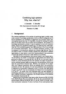
The objective of the case study is to develop a fault-tolerant server system SYS for the client-server con guration, whose complete architectural decomposition is depicted in Figure 1. The task of SYS is to read inputs x from the CLIENT application on channel app tx and return the result of a computation y := f (x ) on the receive channel app rc .
CLIENT app_tx
app_rc
SYS APPTX
APPRC
a
b
DCP CP0
CP1 c1
NET0
NET1 c0
a02
b02
a12
APP0
b12
APP1
off0
FHYP Failure of Master CP0
Figure 1. Architectural decomposition of the fault-tolerant server system. The server SYS shall be designed as a dual-computer system operating in master-standby mode. As long as at least one of the computers is operable (below we will only consider the failure of the master computer), the following functionality shall be guaranteed: 1. SYS returns results in the order of the corresponding inputs. 2. SYS delivers a result after a globally bounded number of internal events following the corresponding input. 3. Analogously, SYS always accepts another input after a globally bounded number of internal events following the preceding input. In these requirements, \globally bounded" means that the response time determined by the number of internal events between input and output is bounded
by a constant which does not depend on the speci c executions performed3 . Before presenting the systematic top-down development according to the invent&verify paradigm in the subsequent sections, it is helpful to sketch the general idea of the fault-tolerance concept. The application layer of the client computer is supported by a network layer consisting of processes APPTX and APPRC implementing a lter by means of an alternating bit protocol. Process APPTX associates an alternating bit b with every client job x received on app tx and broadcasts the resulting message (x ; b ) on channel a to the dual computer DCP , where it is received by both CP0 and CP1 . I [SYS] R [SYS]
V[SYS] D[SYS]
I[APPTX] R [APPTX]
I [DCP] R [DCP]
I[APPRC] R [APPRC]
V[DCP] V
[APPTX]
V
[APPRC]
D[DCP]
I[APPTX]
I [CP0]
P [APPTX]
I [CP1]
R [CP0]
I [FHYP] R [FHYP]
R [CP1]
V[CP0] D[CP0]
I[APPRC] P [APPRC]
V[CP1] D[CP1]
I [NET0]
I [APP0]
I [NET1]
I [APP1]
P [NET0]
P [APP0]
P [NET1]
P [APP1]
Figure 2. Development tree for fault-tolerant system SYS . As long as both computers are operable, the master CP0 performs the compu3
Note that this implies non-divergence of SYS and is a stronger requirement than the predicate NODIV introduced in [16, p. 125], stating that the internal events are bounded by a function of the number of visible events already produced.
tation y := f (x ) and returns the result together with the identi cation bit b on channel b . The standby computer CP1 stores the original input (x ; b ), until it receives an acknowledge on channel c1 . If the master computer fails, the failure event o�0 will also be sensed by the standby CP1 , who then takes over and processes the jobs received from the client. If CP0 failed while still working on job (x ; b ), this is detected by CP1 since the corresponding acknowledge on c1 is still missing. In this case CP1 will redo this job in place of CP0 and return the result (f (x ); b ) to the client. If the failure of CP0 occurred after having delivered the computation result on b and before sending the acknowledge on c1 to CP1 , this will lead to a duplicated computation (f (x ); b ) arriving at the lter APPRC . The duplication is detected by this process by evaluation of the bit b , and the super uous message is not passed on to the client application via channel app rc but discarded instead. In the sections to follow, the systematic development of SYS following the invent&verify paradigm will be presented. Figure 2 presents a development tree arranging the interface de nitions, requirements speci cations, architectural decompositions and veri cation obligations created during the development in topdown fashion.
3 Data Dictionary In this section, the data types, constants, channels and generic speci cations used in subsequent development steps are de ned. These de nitions may be regarded as the data dictionary of our development, where all relevant de nitions are maintained in a central database.
TYPE DEFINITIONS: [DATA] BIT == f0; 1g Type DATA is unspeci ed, but assumed to be nite; the development below will be generic in DATA and in the data transformation function f : DATA ! DATA
applied by the computation server SYS . id : DATA ! DATA
denotes the identity function. In addition, we will use an auxiliary function
� : (DATA � BIT )� ! (DATA � BIT )�
operating as a lter function on sequences of (data ; bit )-pairs by deleting entries containing the same bit-value as their predecessor. � is recursively de ned by
�(h i) =df h i �(s a h(x ; b )i) =df if #s > 0 ^ bit (last (s )) = b then �(s ) else �(s ) a h(x ; b )i Function data : (DATA � BIT ) ! DATA
denotes the projection of a pair (x ; b ) on its data component x , function bit : (DATA � BIT ) ! BIT
the projection on b .
CHANNEL DEFINITIONS: channel channel channel channel channel channel channel channel channel channel channel
app tx : DATA app rc : DATA a : DATA � BIT b : DATA � BIT a02 : DATA b02 : DATA a12 : DATA b12 : DATA o�0 c0 c1
In these de nitions, channels without associated data type are considered as unstructured signals. We use auxiliary functions val and ch generically de ned on channel events c :x by val (c :x ) =df x and ch (c :x ) =df c . For any function g : X ! Y we use notation g � : X � ! Y � for the lifting of g to sequences over X and Y ; g � (hx1 ; : : : xn i) =df hg (x1 ); : : : g (xn )i. It is useful to introduce some implicit speci cations about traces and refusals that are generic with respect to channels, data transformation functions and bounding functions. It will turn out that several processes to be introduced during the development will satisfy instances of these speci cations. Speci cation NO BLOCK is generic in the list of input channels ini and output channels outj and states that either all inputs or at least one output are accepted, which is the essential non-blocking property of pipes: NO BLOCK [(in1 ; : : : ; inn ); (out1 ; : : : ; outm )](s ; R) �df fj in1 ; : : :; inn jg \ R = ; _ fj out1 ; : : : ; outm jg 6� R
Notation fj c jg is used for the set of all events c :x where x is an element of the channel alphabet �(c ). Speci cation LEFT GUARD states the safety property that the number of output events contained in a trace is bounded by an N -valued function of the trace restricted to its inputs. LEFT GUARD [(in1; : : : ; inn ); (out1 ; : : : ; outm ); ](s ) �df #(s � fj out1 ; : : : ; outm jg) � (s � fj in1 ; : : :; inn jg)
As bounding function : � � ! N we will mostly use n � #(�), that is, the length of a trace multiplied by a factor n 2 N . The COPY -speci cation describes how inputs are mapped to outputs. This is expressed by de ning functions f1 : A� ! A� and f2 : A� ! A� , so that application of f2 to the sequence of output values in the trace equals a pre x of the sequence of the input values transformed by f1 . (The set A denotes the union of all channel alphabets, that is, the functions fi are applied to the values that may be passed along input and output channels.) COPY [(in1 ; : : : ; inn ); f1 ; (out1 ; : : :; outm ); f2 ; N ](s ) �df f2 (val � (s � fj out1; : : : ; outm jg)) �N f1 (val � (s � fj in1 ; : : :; inn jg))
4 Top-Level Requirements The requirements for the server SYS can be formalised by the system interface de nition
INTERFACE DEFINITION I [SYS ]: DEFINITION: INPUTS: OUTPUTS:
I (SYS ) =df fj app tx ; app rc jg app tx app rc
and the implicit speci cation
REQUIREMENTS SPECIFICATION R[SYS ]: IMPORT: I [SYS ] IMPLICIT REQUIREMENT: SYS n (� ? I (SYS )) sat SSYS (s ; R) IMPLICIT SPECIFICATION:
SSYS (s ; R) �df NO BLOCK [(app tx ); (app rc )](s ; R) ^ COPY [(app tx ); f � ; (app rc ); id � ; N ](s )
The pair (I [SYS ]; R[SYS ]) is depicted as the root of the development tree shown in Figure 2. Functions f ; id and the channels referenced are de ned in the data dictionary above. N = 3 is a constant xing the bu�ering depth allowed for the server. R[SYS ] requires that SYS shall never block communication on both interface channels at the same time and that the results returned on the output channel are a pre x of the sequence resulting from application of f to each input value.
5 Invent&Verify Steps for SYS
5.1 Decomposition of SYS Into DCP , APPTX and APPRC
The rst invent step leads us to the introduction new process variables DCP , APPTX and APPRC . These variables are free at the present state of the development, they will be bound to concrete processes in subsequent steps. The \black box" denoted by DCP will be decomposed into the dual computer system. The other two processes will act as alternating bit lter processes. These components communicate over channels a and b that carry both the data and alternating bits.
Interface De nitions. To formalise this architectural decomposition, we rst de ne interfaces for the new components (see Figures 1 and 2). The interface for APPTX is given by INTERFACE DEFINITION I [APPTX ]: DEFINITION: INPUTS: OUTPUTS:
I (APPTX ) =df fj app tx ; a jg app tx a
The interface for APPRC is given by
INTERFACE DEFINITION I [APPRC ]: DEFINITION: INPUTS: OUTPUTS:
I (APPRC ) =df fj app rc ; b jg b app rc
The interface for DCP is given by
INTERFACE DEFINITION I [DCP ]: DEFINITION: INPUTS: OUTPUTS:
I (DCP ) =df fj a ; b jg a b
Architectural Decomposition. Referring to the new process variables and interfaces de ned above, the architectural decomposition of SYS into the new components is speci ed by ARCHITECTURAL DECOMPOSITION D[SYS ]: IMPORT: I (SYS ); I (APPTX ); I (APPRC ); I (DCP ) DECOMPOSITION:
SYS = DSYS (APPTX ; DCP ; APPRC ) DSYS (APPTX ; DCP ; APPRC ) =df (APPTX k (DCP k APPRC )) a
b
Requirements Speci cations. The invent step is completed by describing
the speci cations to be ful lled by the three processes, as far as visible at their interfaces. Process APPTX inputs on channel app tx and outputs the input data associated with alternating bits on a . It never blocks both inputs and outputs; moreover, the number of outputs is guarded by the number of inputs received.
REQUIREMENTS SPECIFICATION R[APPTX ]: IMPORT: I [APPTX ] IMPLICIT REQUIREMENT: APPTX n (� ? I (APPTX )) IMPLICIT SPECIFICATION:
sat STX (s ; R)
STX (s ; R) �df NO BLOCK [(app tx ); (a )](s ; R) ^ LEFT GUARD [(app tx ); (a ); #(�)](s ) ^ COPY [(app tx ); f � ; (a ); f � � data � � �; 1](s )
Observe that the computation function f only appears in the COPY speci cation to facilitate the derivation of the composed functionality of the three processes, that is, the property COPY [(app tx ); f � ; (app rc ); id � ; N ](s ). The alternating-bit property is implicitly expressed by the function � de ned above: Since APPTX never blocks at its interface and the length of the output trace ltered by � must not be shorter than the length of the input trace minus 1, the process has to associate alternating bits, because otherwise COPY [(app tx ); f � ; (a ); f � � data � � �; 1](s ) cannot be satis ed. The dual computer system DCP has the interface behaviour of a non-blocking pipe which transforms input data by f . The output messages may be replicated, but at most once for each message. (The lower design levels will strengthen this
property such that messages will only be duplicated if the master computer fails after having delivered a job and before having sent the acknowledgement to the standby computer.)
REQUIREMENTS SPECIFICATION R[DCP ]: IMPORT: I [DCP ] IMPLICIT REQUIREMENT: DCP n (� ? I (DCP )) sat SDCP (s ; R) IMPLICIT SPECIFICATION:
SDCP (s ; R) �df NO BLOCK [(a ); (b )](s ; R) ^ LEFT GUARD [(a ); (b ); 2 � #(�)](s ) ^ COPY [(a ); f � � data � � �; (b ); data � � �; 1](s )
The lter process APPRC has the analogous non-blocking and left-guardedness properties as the others. The COPY -speci cation states that the sequence of output values shall be a 1-pre x of the projection to the DATA-component of the input sequence ltered by �.
REQUIREMENTS SPECIFICATION R[APPRC ]: IMPORT: I [APPRC ] IMPLICIT REQUIREMENT: APPRC n (� ? I (APPRC )) sat SRC (s ; R) IMPLICIT SPECIFICATION:
SRC (s ; R) �df NO BLOCK [(b ); (app rc )](s ; R) ^ LEFT GUARD [(b ); (app rc ); #(�)](s ) ^ COPY [(b ); data � � �; (app rc ); id � ; 1](s )
5.2 Veri cation of the SYS -Decomposition: Generic Theories The invent-step performed in the decomposition of SYS above induces the following proof obligation:
VERIFICATION OBLIGATION V [SYS ]: IMPORT: R[APPTX ]; R[DCP ]; R[APPRC ]; R[SYS ]; D[SYS ] HIGHER-LEVEL REQUIREMENTS: R[SYS ] IMPLIED BY: lower-level requirements: R[APPTX ]; R[DCP ]; R[APPRC ] architectural decomposition: D[SYS ]
To discharge this veri cation obligation, we proceed by performing the steps (1) Strategy Selection, (2) Theorem Selection, (3) Theory Instantiation and (4) Veri cation; this will be illustrated in the following paragraphs.
Strategy Selection. Observe that the architectural decomposition SYS = DSYS (APPTX ; DCP ; APPRC ), when restricted to the interfaces I (APPTX ), I (DCP ), I (APPRC ) de nes just a composition of pipes, that is, SYS n (� ? I (SYS )) = APPTX >>DCP >>APPRC
where the pipe operator is de ned for pipes P with channels in ; mid and Q with channels mid ; out as P >>Q =df (P k Q ) n (� ? fj in ; out jg). As a consequence mid it is a promising strategy to apply a generic (generalised) pipe theory for discharging V [SYS ]. In the context of generic theories, the HOL tool is applied for two objectives:
{ Development of new generic theories, { application of instantiated theories in concrete proofs. The generic pipe theory to be applied in veri cation obligation V [SYS ] generalises the existing pipe theory contained in [16] by admitting several input and output channels per pipe. It has been completely veri ed using the HOL-tool (details are described in the technical report [7]). Another application of the theory in an industrial veri cation project is described in [6].
Theorem Selection. Having decided on which generic theory to use, the next step consists in the selection of appropriate generic theorems provided by the theory. For the veri cation of V [SYS ], two theorems from the pipe theory are
of particular interest: The PIPE COPY theorem allows to derive COPY [: : :](s )-properties for composed pipes P >>Q , where the generic COPY [: : :](s )-predicate is de ned in the data dictionary above:
PIPE_COPY =
`
8(left:chan 8(f1:(alpha
8
8
?
list) mid right. (P:buffer) Q. f:trace list) >(alpha list)) f2 f3. (N:num) M. ((SAFE_PIPE P Q left mid right f) ((P left mid) trsat (COPY left f1 mid f2 N)) ((Q mid right) trsat (COPY mid f2 right f3 M)))
?
^
8
)
>num.
^
+
(pipe P Q left mid right) trsat (COPY left f1 right f3 (N M))
The theorem is presented in the syntax of the HOL encoding for CSP and the pipe theory. trsat denotes satisfaction of trace speci cations, P sat S (h ). (COPY mid f2 right f3 M) stands for COPY [mid ; f 2; right ; f 3; M ](h ). The theorem explains the input-output behaviour of composed pipes by deriving the COPY speci cation for P >>Q from the COPY speci cations of the isolated processes. For applicability of the theory it is necessary that P and Q should satisfy some well-formedness conditions that guarantee non-blocking and nondivergence of P >>Q . These are summarised in the SAFE PIPE predicate and require that (1) output channels must not feed back into input channels, (2) the isolated pipes are non-blocking and (3) P must be left-guarded. Another theorem provided by the pipe theory is concerned with the proof of NO BLOCK [: : :](s ; R)-properties: SAFE_PIPE_NO_BLOCK
` 8in
mid out P Q f. SAFE_PIPE P Q in mid out f (pipe P Q in mid out) sat (NO_BLOCK in out)
)
Theorem SAFE PIPE NO BLOCK states that the non-blocking property for a composition of pipes P >>Q can be derived from the isolated pipes P and Q , if these satisfy the SAFE PIPE condition.
Theory Instantiation. Next, we instantiate the theorems selected above for
the di�erent situations where they should be applied. This results in a series of lemmas stated for the concrete process names, channels and constants involved. As an example, we instantiate the PIPE COPY theorem for the composed pipe APPTX >>DCP : Lemma 5.1. If 1. APPTX and DCP satisfy the SAFE PIPE condition for channels (app tx ; a ; b ), 2. APPTX n (� ? I (APPTX )) sat COPY [(app tx ); f � ; (a ); f � � data � � �; 1](s ), 3. DCP n (� ? I (DCP )) sat COPY [(a ); f � � data � � �; (b ); data � � �; 1](s ), then APPTX >>DCP sat COPY [(app tx ); f � ; (b ); f � � data � � �; 2](s ) follows.
ut
instantiated for APPTX >>DCP leads to Lemma 5.2. If APPTX and DCP satisfy the SAFE PIPE condition for channels (app tx ; a ; b ), then APPTX >>DCP sat NO BLOCK [(app tx ); (b )](s ; R) follows. ut Similar lemmas derived from PIPE COPY and SAFE PIPE NO BLOCK can be stated for the composed pipe (APPTX >>DCP )>>APPRC . The SAFE
PIPE NO BLOCK
Veri cation. The veri cation obligation V [SYS ] is mechanically discharged by applying the lemmas above in the HOL framework. In our encoding of the generic pipe theory, V [SYS ] is represented as a HOL theorem: SYS_CORRECT =
`
(BUFFER_ALPHA APPTX [`apptx`] [`a`]) (BUFFER_ALPHA DCP [`a`] [`b`]) (BUFFER_ALPHA APPRC [`b`] [`apprc`])
^
^ ^
((APPTX [`apptx`] [`a`]) sat (NO_BLOCK [`apptx`] [`a`])) ((DCP [`a`] [`b`]) sat (NO_BLOCK [`a`] [`b`])) ((APPRC [`b`] [`apprc`]) sat (NO_BLOCK [`b`] [`apprc`]))
^
^ ^
((APPTX [`apptx`] [`a`]) sat (LEFT_GUARD [`apptx`] [`a`] LENGTH)) ((DCP [`a`] [`b`]) sat (LEFT_GUARD [`a`] [`b`] du)) ((APPRC [`b`] [`apprc`]) sat (LEFT_GUARD [`b`] [`apprc`] LENGTH))
^
((APPTX [`apptx`] [`a`]) trsat (COPY [`apptx`] (MAP f_data) [`a`] ((MAP f_data) o (MAP m_to_d) o rho) 1)) ((APPTX [`apptx`] [`a`]) trsat (COPY [`apptx`] ab [`a`] I 1)) ((DCP [`a`] [`b`]) trsat (COPY [`a`] ((MAP f_data) o (MAP m_to_d) o rho) [`b`] ((MAP m_to_d) o rho) 1)) ((APPRC [`b`] [`apprc`]) trsat (COPY [`b`] ((MAP m_to_d) o rho) [`apprc`] I 1))
^ ^
^
^
^
) ((SYS_ARCH sat (NO_BLOCK [`apptx`] [`apprc`]))
^ ++
(SYS_ARCH trsat (COPY [`apptx`] (MAP f_data) [`apprc`] I (1 1 1))))
In this HOL theorem, the data transformation function f � is encoded as (MAP f data), function data � as (MAP m to d) and the identity mapping id � on sequences is denoted by I. SYS ARCH denotes the HOL encoding of the architectural decomposition function DSYS de ned in D[SYS ]:
`def
=
SYS_ARCH (pipe APPTX (pipe DCP APPRC [`a`] [`b`] [`apprc`]) [`apptx`] [`a`] [`apprc`])
The predicates BUFFER ALPHA... are well-formedness conditions on bu�er processes that are trivially satis ed for APPTX , DCP and APPRC . The HOL proof of V [SYS ] is carried out along the following lines: At rst it is proved that the processes involved satisfy the SAFE PIPE conditions required in the premise of the lemmas. This follows immediately from the NO BLOCK and LEFT GUARD properties stated for the three processes in their requirements speci cations R[APPTX ], R[DCP ] and R[APPRC ]. Next, we can compose the three COPY speci cations recorded in R(APPTX ), R(DCP ) and R(APPRC ) according to the implications of Lemma 5.1 and the corresponding lemma for (APPTX >>DCP )>>APPRC . This results in APPTX >>DCP >>APPRC sat COPY [(app tx ); f � ; (app rc ); id � ; 3](h )
Finally, we evaluate the implications of Lemma 5.2 and the corresponding lemma for (APPTX >>DCP )>>APPRC and get the required non-blocking property NO BLOCK [(app tx ); (app rc )](s ; R), which completes the proof of V [SYS ]. ut
6 Invent&Verify Step for APPRC 6.1 Implementable Process Speci cation of APPRC For APPRC , no further architectural decomposition is necessary; we invent an explicit implementable representation as a communicating sequential process:
IMPLEMENTABLE PROCESS SPECIFICATION P [APPRC ]: IMPORT: I [APPRC ] EXPLICIT SPECIFICATION:
APPRC = b ?(y ; d ) ! app rc !y ! RC (1 ? d ) RC (e ) = b ?(y ; d ) ! if d = e then app rc !y ! RC (1 ? e ) else RC (e ) APPRC is implemented as a process which lters incoming messages (y ; d ) on channel b by discarding messages carrying the same bit as the preceding ones. The data component of accepted messages is delivered to the application layer via channel app rc . Observe that P [APPRC ] binds the process variable APPRC
by means of a (recursive) process equation. This variable binding is the formal indicator for the fact that no further decompositions are necessary for APPRC . As a consequence, P [APPRC ] is represented as a leaf in the development tree shown in Figure 2.
6.2 Veri cation of APPRC
The implementable process representation de ned in P [APPRC ] has to satisfy the requirements R[APPRC ]; this induces the
VERIFICATION OBLIGATION V [APPRC ]: IMPORT: R[APPRC ]; P [APPRC ] HIGHER-LEVEL REQUIREMENTS: R[APPRC ] IMPLIED BY: implementable process speci cation: P [APPRC ]
Strategy Selection. Since P [APPRC ] speci es APPRC as a sequential process, we apply the strategy to map APPRC into its associated nondeterministic sequential program � (APPRC ) and verify the requirement APPRC sat SRC (s ; R) stated above in R[APPRC ] by performing the corresponding invariant proof on � (APPRC ) inv SRC (sv ; Rv ). This process will be illustrated in the following steps. Transformation of APPRC Into Normal Form. The pre-requisite for the transformation into the sequential program domain is a speci c syntactic representation of the sequential CSP process, called (second) normal form according to Apt and Olderog [1, 3]. A CSP process in normal form has syntactic structure P = Q (v1 ; : : :; vn ) Q (x1 ; : : :; xn ) = j gj (x1 ; : : : ; xn )&cj ! Q (f1j (x1 ; : : : ; xn ); : : : ; fnj (x1 ; : : :; xn )) where the gj are communication guards depending on the parameters xi and the cj are inputs d !h (x1 ; : : : ; xn ) or outputs e ?xi on channels d ; e of P . After such a channel communication, the process enters the next recursion with parameters changed according to functions fij . The standard procedure for normal form transformations preserving the process semantics is to introduce an auxiliary process parameter state identifying the syntactic location of a communication command in the original process and using this parameter to construct communication guards gj . For APPRC , this procedure leads to the transformed process j
N (APPRC ) = NAPPRC (0; 0; 0) NAPPRC (state ; y ; e ) = (state = 0)&b ?(y ; d ) ! NAPPRC (1; y ; d )
(state = 1)&app rc !y ! NAPPRC (2; y ; 1 ? e ) (state = 2)&b ?(y ; d ) ! (if d = e then NAPPRC (3; y ; e ) else NAPPRC (2; y ; e )) (state = 3)&app rc !y ! NAPPRC (2; y ; 1 ? e )
Transformation Into the Sequential Program Domain. The transformation into the nondeterministic sequential program � (APPRC ) takes N (APPRC ), replaces communications by variable assignments and introduces the auxiliary variables sv and Rv modelling the trace performed so far and the refusal valid in the actual state. This results in the program � (APPRC ) = state := 0; sv := h i; Rv := fj app rc jg; do
2(z w ):DATA�BIT ((state = 0) ! (y ; d ) := (z ; w ); state := 1; sv := sv a hb :y :d i; ;
Rv := fj b jg; )
2
(state = 1) ! z := y ; e := 1 ? d ; state := 2; sv := sv a happ rc :y i; Rv := fj app tx jg;
2 2(z w ):DATA�BIT ((state = 2) ! (y ; d ) := (z ; w ); ;
od
if d = e then state := 3; else SKIP ; sv := sv a hb :y :d i; Rv := if state = 3 then fj b jg else fj app tx jg; ) 2 (state = 3) ! z := y ; e := 1 ? d ; state := 2; sv := sv a happ rc :y i; Rv := fj app tx jg;
Veri cation Using PAMELA/PVS. The proof obligation for APPRC can
now be discharged in the sequential program domain interpreted in the operational semantics de ned by Apt and Olderog [3]: In [18, p. 99, Theorem 6] we
have shown that the CSP process requirement APPRC sat SRC (s ; R) is equivalent to the requirement
� (APPRC ) inv SRC (sv ; Rv ) on the non-deterministic program � (APPRC ). This requirement states that predicate SRC (sv ; Rv ) is an invariant of the do : : : od-loop. Veri cation of sequential programs based on Hoare-style axiomatisations using pre- and post conditions can be performed using the PAMELA/PVS tool. The mechanised veri cation of the invariant does not show any errors.
7 Invent&Verify Step for APPTX 7.1 Explicit Speci cation of APPTX In analogy to APPRC , APPTX is de ned as a sequential process:
IMPLEMENTABLE PROCESS SPECIFICATION P [APPTX ]: IMPORT: I [APPTX ] EXPLICIT SPECIFICATION:
APPTX = TX (0) TX (e ) = app tx ?x ! a !(x ; e ) ! TX (1 ? e )
Process APPTX will be implemented as a process which adds alternating bits e , starting with e = 0 to inputs x received on channel app tx and outputs the pairs (x ; e ) on channel a . We skip the veri cation of the proof obligation APPTX sat STX (s ; R), because this is performed in analogy to the veri cation of APPRC .
8 Invent&Verify Step for DCP 8.1 Decomposition of DCP Into Dual Computers CP0 and CP1 As stated in the informal system description above, component DCP shall be designed as a fault-tolerant sub-system using a dual computer technique. The invent step performed in this section deals with the introduction of the dual computers and the hypotheses about their exceptional behaviour. The dual computers are represented by the free process variables CP0 and CP1 , the assumptions about possible system failures will be explicitly modelled by a process FHYP .
Interface De nitions. Both computers receive inputs on channel a in a synchronous way and output independently on channel b (see architectural decomposition D[DCP ] below). In addition, they exchange control signals on channels c ; c and react on control signal o� which models the crash of computer CP . This leads to symmetric interface de nitions I [CPi ]; i = 0; 1: 0
1
0
0
INTERFACE DEFINITION I [CPi ]: DEFINITION: INPUTS: OUTPUTS:
I (CPi ) =df fj a ; b ; c0 ; c1 ; o�0 jg a ; ci ; o�0 b ; c(1?i )
In our simpli ed example, the fault hypotheses modelled in CSP process FHYP use a single event (in the full example described in [18], the fault hypotheses synchronise a several failure and communication events):
INTERFACE DEFINITION I [FHYP ]: DEFINITION: INPUTS: OUTPUTS:
I (FHYP ) =df fj o�0 jg o�0
Architectural Decomposition. For the decomposition of DCP , the inter-
action between dual computers CP0 and CP1 and fault hypotheses FHYP is speci ed by the following
ARCHITECTURAL DECOMPOSITION D[DCP ]: IMPORT: I (CP0 ); I (CP1 ); I [FHYP ] DECOMPOSITION:
DCP = DDCP (CP0 ; CP1 ; FHYP ) DDCP (CP0 ; CP1 ; FHYP ) =df ((CP0 o�r0 RUN (fj a ; c0 jg))
k
CP1 ) k FHYP
fjo�0 c0 c1 a jg ;
;
;
fo�0 g
As indicated above, the two computers exchange control messages on channels c0 ; c1 . The event o�0 denotes failure of CP0 which then performs a transition into the idle mode RUN (fj a ; c0 jg) indicating that CP0 will stop to produce outputs on b or c1 , but also won't block any a - or c0 -communications after a crash. Failure event o�0 it is also detected by CP1 which initiates the recovery activities in the standby computer. This will become apparent in the next decomposition step.
Requirements Speci cations. We start with the speci cation of FHYP . Our simpli ed example covers the situation where computer CP0 is initialised to act as the master computer. The master may or may not fail, but in order to keep the example small, we do not consider a crash of the standby computer CP1 or the re-integration of repaired components and consecutive failure situations (this is described in [18]). These assumptions are modelled explicitly by the following speci cation. REQUIREMENTS SPECIFICATION R[FHYP ]: IMPORT: I [FHYP ] EXPLICIT REQUIREMENT: FHYP = o�0 ! STOP u STOP
Process FHYP admits at most one crash of CP0 . Since the failure event o�0 is synchronised between FHYP and the \real" components CP0 ; CP1 , the auxiliary k CP ) to process restricts the set of all executions possible for (CP0 fjo�0 c0 c1 a jg 1 those where at most one crash happens. Observe that it is not intended to implement R[FHYP ]. The speci cation just models our assumptions about the faults that may occur, and we prove that the dual computer system acts according to its speci cation as long as these assumptions are valid. For these reasons, R[FHYP ] is depicted by a dashed-line box in Figure 2. To motivate the requirements speci cations for CP0 and CP1 below, it is important to look ahead at the strategy to be applied in the proof that the dual computers implement the higher-level requirements R[DCP ]: Our plan is to separate the full veri cation obligation V [DCP ] arising from the present decomposition step into two parts, where the rst can be veri ed by simple compositional reasoning, while the second, more complex, part can be veri ed by model checking in a completely automatic way. Now "classical" model checking as supported by the FDR tool requires nite-state processes, nite (preferably small) data ranges and does not admit generic data types DATA or transformations f . Therefore the explicit requirements speci cations to be analysed by the model checker must refer to nite-state/ nite-value abstractions of CPi . For our purposes, a simple abstraction type is already powerful enough (more complex abstraction techniques have been described in [6]): It can be expressed by renaming of events, and the renaming is performed in such a way that all references to generic data types and functions vanish in the abstraction process. Formally, our abstraction mapping is given by ;
;
;
ABSTRACTION DEFINITION A: ABSTRACTION:
A(X ) =df X [[ a :x :bit a :bit ; b :x :bit b :bit ; ai 2 :x j x : DATA; bit : BIT ; i : f0; 1g]]
ai 2 ; bi 2 :x
bi 2
In this de nition, P [[c d ]] denotes process P with all occurrences of c replaced by d . With these preliminary considerations, the speci cation of master computer CP0 is given by
REQUIREMENTS SPECIFICATION R[CP0 ]: IMPORT: I [CP0 ] 0 (s ; R) IMPLICIT REQUIREMENT: CP0 n (� ? I (CP0 )) sat SDCP IMPLICIT SPECIFICATION: 0 (s ) �df (9 y : DATA; d : BIT � last (s ) = b :y :d ) SDCP ) y = f (data (last (s � a )))
EXPLICIT REQUIREMENT: X0 vFD A(CP0 n (� ? I (CP0 )) EXPLICIT SPECIFICATION: X0 = a ?d ! b !d ! c1 ! X0
The implicit part of R[CP0 ] is generic in DATA and f and states everything we need to ensure about the data transformation behaviour of CP0 : The computer always outputs on channel b the most recent data input received on a , 0 (s ), betransformed by function f . The implicit speci cation is denoted by SDCP 00 cause together with another speci cation SDCP (s ) to be de ned below, it implies the implicit speci cation SDCP (s ; R) de ned for DCP in R[DCP ]. The explicit part of CP0 's requirements speci cations refers to input/output sequencing and to the bit-values passed along channels a and b : As a re nement of X , CP0 will always service its communication channels in the order a ; b ; c1 ; a ; : : :. The most recent bit-value d received on a will be returned to the environment on b . For the speci cation of CP0 , the requirements related to data transformations are the same, since the computer must be capable of performing exactly the same service as CP0 . However, the explicit speci cation is more complex, since it also models the reaction on failure event o�0 indicating the crash of master computer CP0 (in [18], fully symmetric speci cations for CPi are given, dealing with the failure of both computers). Requirements R[CP1 ] are given by
REQUIREMENTS SPECIFICATION R[CP1 ]: IMPORT: I [CP1 ] 0 (s ; R) IMPLICIT REQUIREMENT: CP1 n (� ? I (CP1 )) sat SDCP IMPLICIT SPECIFICATION: 0 (s ) �df (9 y : DATA; d : BIT � last (s ) = b :y :d ) SDCP ) y = f (data (last (s � a )))
EXPLICIT REQUIREMENT: X1 vFD A(CP1 n (� ? I (CP1 )) EXPLICIT SPECIFICATION:
X1 = a ?d ! (c1 ! X1 o�0 ! b !d ! c0 ! X10 ) o�0 ! X10 0 X1 = a ?d ! b !d ! c0 ! X10
The explicit speci cation states that CP1 stores the most recent bit received on a until an acknowledge from CP0 is received on c1 . If a crash occurs before this acknowledge has been received, the associated b -output is repeated. After a crash, CP1 services channels a ; b ; c1 in analogy to CP0 .
8.2 Veri cation of the DCP -Decomposition: Compositional Reasoning and Model Checking
The invent step for DCP performed in the previous section give rise to the following veri cation obligation:
VERIFICATION OBLIGATION V [DCP ]: IMPORT: R[DCP ]; R[CP0 ]; R[CP1 ]; R[FHYP ]; D[DCP ] HIGHER-LEVEL REQUIREMENTS: R[DCP ] IMPLIED BY: lower-level requirements: R[CP0 ]; R[CP1 ]; R[FHYP ] architectural decomposition: D[DCP ]
Strategy Selection. As indicated above, our goal is to decompose requirement R[DCP ] into two parts in order to separate speci cations referring to generic data types and functions from those referring only to nite data ranges and sequencing of events. The two speci cations are de ned by
0 (s ) �df (9 y : DATA; d : BIT � last (s ) = b :y :d ) SDCP ) y = f (data (last (s � a ))) 00 (s ; R) �df SDCP NO BLOCK [(a ); (b )](s ; R) ^ ch � (s ) 2 pref ha; [b j b; b]i� ^ ((9 d : BIT � (ch � bit )(last (s )) = b :d )) ) d = bit (last (s � a ))) 0 (s ) has already been introduced above. Speci cation S 00 (s ; R) where SDCP DCP states that 1. DCP n (� ? I (DCP )) will never deadlock on its interface fj a ; b jg, 2. DCP n (� ? I (DCP )) always accesses its interface channels in the order de ned by the regular expression ha ; [b j b ; b ]i� , that is, each a -event will be followed by one or two b -events, 3. DCP n (� ? I (DCP )) will always output on b the last bit value received on channel a . Our approach is justi ed by the following lemma: 0 (s ; R) ^ S 00 (s ; R) holds, Lemma 8.1. If DCP sat SDCP DCP then DCP sat SDCP (s ; R) follows. Proof. The NO BLOCK and LEFT GUARD conjuncts in SDCP (s ; R) are di00 (s ; R). The two speci cation SDCP (s )0 and S 00 (s ; R) rectly implied by SDCP DCP together imply that every trace of DCP performed at its interface fj a ; b jg is a pre x of
ha :(x ; d ); [b :(f (x ); d ) j b :(f (x ); d ); b :(f (x ); d )]; a :(x ; d ); [b :(f (x ); d ) j b :(f (x ); d ); b :(f (x ); d )]; : : :i with suitable data values xi and bit values di . This implies data � � �(s � b ) � f � � data � � �(s � a ), so that the COPY predicate in SDCP (s ; R) is also induced by the new speci cations. ut 1
1
1
1
2
2
1
2
1
2
1
1
2
2
2
2
1
0 (s ) is a trace assertion, it should be easy to verify this property Since SDCP using the compositional proof theory of CSP interpreted in the trace model. 00 (s ) does not refer to DATA and f . As a consequence, our Speci cation SDCP 00 (s ) in the followde nition A speci es a valid abstraction for speci cation SDCP 4 ing sense : 00 (s ) implies P sat S 00 (s ). For all processes P , A(P ) sat SDCP DCP Since satisfaction relations are preserved under re nement, our veri cation strategy can now be summarised as follows: 4
00 Observe that since it does not refer to values y : DATA, speci cation SDCP (s ) is well-de ned for both traces over the original channel events a x d b x d and the abstracted events a d b d . Otherwise it would be necessary to de ne a \lifted" 00 speci cation A� (SDCP (s )) de ned on the abstracted trace space. :
:
;
:
:
;
:
:
1. Use compositional reasoning to prove that the implicit speci cation parts of 0 (s ). R[CPi ] imply that DDCP (CP0 ; CP1 ; FHYP ) satis es SDCP 00 (s ; R) and prove 2. Find a simple explicit process Y obviously satisfying SDCP by model checking that Y v A(DDCP (X0 ; X1 ; FHYP )) with Xi de ned as in R[CPi ]. 3. Conclude from step 2 that the decomposition DDCP (CP0 ; CP1 ; FHYP ) sat00 (s ; R). is es SDCP
Veri cation by Compositional Reasoning. Since R[CPi ] state that com-
puters CPi shall both satisfy SDCP (s )0 , the rst part of our veri cation obligations is expressed by the following lemma which can be proved using our HOL encoding:
Lemma 8.2. With the de nitions given in R[DCP ], R[CP ], R[CP ],R[FHYP ] and D[DCP ], CP n (� ? I (CP )) sat SDCP (s )0 and 0 (s ) CP n (� ? I (CP )) sat SDCP (s )0 implies DCP n (� ? I (DCP )) sat SDCP Proof. According to the decomposition DCP = DDCP (CP ; CP ; FHYP ) de ned in D[DCP ], we have to show that 0 (s ) DDCP (CP ; CP ; FHYP ) n (� ? I (DCP )) sat SDCP 0
0
1
1
0
1
0
0
1
1
holds. Speci cation SDCP (s )0 refers only to channels a and b which are not hidden in any of the three processes. Therefore the proof is performed by multiple application of the compositional law P sat SP (h ) and Q sat SQ (h ) implies (P k Q ) sat (SP (h � �(P )) ^ SQ (h � �(Q ))) 0 (s ) and which holds in the trace model of CSP: CP0 and CP1 both satisfy SDCP 0 (s ) is also satis ed by their parallel synchronise over a , as a consequence SDCP composition. Moreover, FHYP and the interrupt o�r0 do not produce any a - or b -events. This proves the lemma. ut
Veri cation by Model Checking. Next, we turn to the second speci cation, and it will be shown that its validity is implied by the explicit speci cation parts in R[CP0 ] and R[CP1 ]. This is stated in the following lemma: Lemma 8.3. With the de nitions given in R[DCP ], R[CP ], R[CP ],R[FHYP ] and D[DCP ], X vFD A(CP n (� ? I (CP )) and X vFD A(CP n (� ? 00 (s ; R) I (CP )) implies DCP n (� ? I (DCP )) sat SDCP 0
0
0
0
1
1
Proof. In analogy to the previous lemma, we have to show that 00 (s ; R) DDCP (CP0 ; CP1 ; FHYP ) n (� ? I (DCP )) sat SDCP
1
1
holds. Following the strategy sketched above, we start by inventing an auxiliary 00 (s ; R). Such a process is given by process Y which obviously satis es SDCP Y = a ?bit ! (b !bit ! Y u b !bit ! b !bit ! Y ) (This could also be checked using the transformation of Y into the corresponding nondeterministic sequential program to be veri ed by the PAMELA/PVS tool.) Failures-Divergence re nement preserves satisfaction relations and it has 00 (s ; R) implies P sat S 00 (s ; R) for all been noted above that A(P ) sat SDCP DCP processes P . As a consequence, it su�ces to verify Y vFD A(DDCP (CP0 ; CP1 ; FHYP ) n (� ? I (DCP ))) in order to prove the lemma. Next, we observe that A(DDCP (CP0 ; CP1 ; FHYP ) n (� ? I (DCP ))) = DDCP (A(CP0 ); A(CP1 ); FHYP ) n (� ? I (DCP )) where channels a and b occurring in the terms on the right-hand side of the equation denote the abstracted versions without DATA-components x . Since re nement is compositional, the re nement relations Xi vFD A(CPi n (� ? I (CPi )) asserted in R[CPi ] imply DDCP (X0 ; X1 ; FHYP ) n (� ? I (DCP )) vFD DDCP (A(CP0 n (� ? I (CP0 )); A(CP1 n (� ? I (CP1 )); A(FHYP )) n (� ? I (DCP )) The right-hand side of this re nement relation is identical to DDCP (A(CP0 ); A(CP1 ); FHYP ) n (� ? I (DCP )), because I (DCP ) is a subset of both I (CP0 ) and I (CP1 ). Since vFD is transitive, the desired re nement relation Y vFD DDCP (A(CP0 ); A(CP1 ); FHYP ) n (� ? I (DCP )) would follow if we could prove Y vFD DDCP (X0 ; X1 ; FHYP ) n (� ? I (DCP )) Now this re nement relation does not contain any free process variables or generic data types or functions. As a consequence, it can be veri ed by model checking using the FDR tool. This check has been performed and does not show any errors, which proves the lemma. ut Together, Lemma 8.1, 8.2 and 8.3 discharge veri cation obligation V [DCP ].
9 Invent&Verify Steps for CP0
9.1 Decomposition of CP0 Into Processes NET0 and APP0
As indicated in Figure 1, each component of the dual computer system is devided into two layers: A network process NETi performs the communication with the environment of DCP and exchanges synchronisation events. An application process APPi performs the computations y := f (x ) on the active computer. For CP0 , this decomposition and its veri cation will be performed in the present section.
Interface De nitions. The interface of the networking component NET is 0
de ned by
INTERFACE DEFINITION I [NET0 ]: I (NET0 ) =df fj a ; b ; c0 ; c1 ; a02 ; b02 jg a ; c0 ; b02 b ; c1 ; a02
DEFINITION: INPUTS: OUTPUTS:
The application process APP0 has interface
INTERFACE DEFINITION I [APP0 ]: I (APP0 ) =df fj a02 ; b02 jg a02 b02
DEFINITION: INPUTS: OUTPUTS:
Architectural Decomposition of CP0 . The two layers operate in parallel and use channels a ; b for internal communication. This gives rise to the following 02
02
architectural decomposition:
ARCHITECTURAL DECOMPOSITION D[CP0 ]: IMPORT: I (NET0 ); I (APP0 ) DECOMPOSITION:
CP0 = DCP0 (NET0 ; APP0 ) DCP0 (NET0 ; APP0 ) =df (NET0
k APP )
fja02 b02 jg ;
0
Explicit Speci cations. Both networking and application layers can be explicitly speci ed as implementable CSP processes. IMPLEMENTABLE PROCESS SPECIFICATION P [NET0 ]: IMPORT: I [NET0 ] EXPLICIT SPECIFICATION:
NET0 = a ?(x ; bit ) ! a02 !x ! b02 ?y ! b !(y ; bit ) ! c1 ! NET0
Process NET0 accepts input data and alternating bits on a . After that, the data part is o�ered to the application layer on channel a02 . If the application layer is active (that is, the local computer acts as master) it will accept the data, and NET0 gets the transformed value y back on channel b02 . The value y is again associated with the bit of the corresponding input message, and the resulting tuple is sent back to the client via channel b . After that, successful completion of the transaction is signalled to the standby computer via channel c1 . Since in the simpli ed example CP0 never acts as standby, NET0 never accepts control signals c0 from NET1 , as long as CP0 is active. The explicit requirements for APP0 just describe the desired data transformation behaviour:
IMPLEMENTABLE PROCESS SPECIFICATION P [APP0 ]: IMPORT: I [APP0 ] EXPLICIT SPECIFICATION: APP0 = a02 ?x ! b02 !f (x ) ! APP0
9.2 Veri cation of the CP0-Decomposition: Compositional Reasoning and Model Checking The veri cation obligation to be discharged for the present development step is
VERIFICATION OBLIGATION V [CP0 ]: IMPORT: R[CP0 ]; P [NET0 ]; P [APP0 ]; D[CP0 ] HIGHER-LEVEL REQUIREMENTS: R[CP0 ] IMPLIED BY: lower-level requirements: P [NET0 ]; P [APP0 ] architectural decomposition: D[CP0 ]
Strategy Selection. R[CP ] contains both an implicit and an explicit require0
ment. The implicit one will be discharged by compositional reasoning about NET0 , APP0 and their parallel composition. The explicit requirement can be veri ed again by model checking.
Veri cation by Compositional Reasoning. The proof obligation to be discharged for the implicit requirement in V [CP ] is given by the following lemma: 0
Lemma 9.1. With the de nitions given in R[CP ], P [NET ], P [APP ], and D[CP ], the explicit speci cations for NET and APP imply 0 (s ) CP n (� ? I (CP )) sat SDCP 0
0
0
0
0
0
0
0
Proof. According to the architectural decomposition D[CP0 ], we have to show that 0 (s ) DCP0 (NET0 ; APP0 ) n (� ? I (CP0 )) sat SDCP 0 (s ) is independent on other channels but a and b , so the The de nition of SDCP proof obligation can be re-formulated as
(NET0
0 (s ) k APP ) sat SDCP
fja02 b02 jg ;
0
with explicit speci cations for NET0 and APP0 according to P [NET0 ] and P [APP0 ]. As in Lemma 8.2, we will make use of the compositional law for the parallel operator in the trace model of CSP. First we observe that the auxiliary assertion NET0 sat SNET0 (s ) SNET0 (s ) �df ((9 x : DATA � last (s ) = a02 :x ) ) x = data (last (s � a )))
^
((9 y : DATA; d : BIT � last (s ) = b :(y ; d )) ) y = data (last (s � b02 ))) is obviously satis ed. This follows directly from the process de nition of NET0 in P [NET0 ], but could also be mechanically proven using PAMELA/PVS. Next we note that APP0 sat SAPP0 (s ) SAPP0 (s ) �df (9 y : DATA � last (s ) = b02 :y ) ) y = f (data (last (s � a02 )))
is also satis ed as follows directly from P [APP0 ]. Application of the k -law results in (NET0
k APP ) sat SNET0 (s ) ^ SAPP0 (s � fj a ; b jg)
fja02 b02 jg ;
0
0 (s ). and this directly implies satisfaction of SDCP
02
02
ut
Veri cation by Model Checking. To verify the explicit requirement stated in R[CP ], we will use model checking. The proof obligation is given in the 0
following lemma: Lemma 9.2. With the de nitions given in R[CP0 ], P [NET0 ], P [APP0], and D[CP0 ], the explicit speci cations for NET0 and APP0 imply X0 vFD A(CP0 n (� ? I (CP0 )) Proof. Evaluating the architectural decomposition D[CP0 ] and the de nitions of A, NET0 and APP0 results in the revised proof obligation X0 vFD (A(NET0 ) k A(APP0 )) n fj a02 ; b02 jg fja02 b02 jg ;
with A(NET0 ) = a ?bit ! a02 ! b02 ! b !bit ! c1 ! A(NET0 ) and A(APP0 ) = a02 ! b02 ! c1 ! A(APP0 ) This re nement relation has been mechanically checked using the FDR tool which showed no errors. This completes the proof of the lemma ut Together, lemmas 9.1 and 9.2 discharge veri cation obligation V [CP0 ].
10 Invent&Verify Steps for CP1
10.1 Decomposition of CP1 Into Processes NET1 and APP1
In analogy to CP0 , computer CP1 is structured into networking process NET1 and application APP1 .
Interface De nitions. The interfaces of NET1 and APP1 are de ned in analogy to those of NET0 and APP0 . Architectural Decomposition of CP1. As for CP , the two layers operate in parallel and use channels a ; b for internal communication. However, the 0
12
12
application layer of CP1 will only become active as a reaction to the crash event o�0 , indicating that CP0 is no longer able to process jobs.
ARCHITECTURAL DECOMPOSITION D[CP1 ]:
IMPORT: I (NET1 ); I (APP1 ) DECOMPOSITION:
CP1 = DCP1 (NET1 ; APP1 ) DCP1 (NET1 ; APP1 ) =df (NET1
k o� ! APP )
fja12 b12 jg ;
0
1
Explicit Speci cations. The explicit speci cation P [APP ] is analogous to P [APP ] de ned above. The networking component of CP has to react on 1
0
acknowledgement signals from CP0 :
1
IMPLEMENTABLE PROCESS SPECIFICATION R[NET1 ]: IMPORT: I [NET1 ] EXPLICIT SPECIFICATION:
NET1 = a ?(x ; bit ) ! (c1 ! NET1 a12 !x ! b12 ?y ! b !(y ; bit ) ! c1 ! NET1 )
Observe that NET1 can only enter the -branch a12 !x ! : : : if the application APP1 is active, that is, after the failure event o�0 has occurred. We skip the de nition and veri cation of obligation V [CP1 ], since it is completely analogous to that of V [CP0 ]. This completes the development and veri cation of the dual computer system according to the invent&verify paradigm.
11 Conclusion Presenting the development of a dual computer system, we have illustrated an approach for the tool-based veri cation of fault-tolerant systems using combinations of speci cation formalisms, proof strategies and associated veri cation tools. Our main objective was to motivate that this combination can be e�ectively applied in complex \real-world" developments. This claim is supported by experiences with the veri cation of a fault-tolerant system developed by DaimlerBenz Aerospace for the International Space Station ISS [6]. It should be noted that the veri cation approach presented in this article is complemented by automated hardware-in-the-loop tests performing real-time tests for the completed hardware and software system [25] using the VVT-RT test tool. To further increase the e�ciency of the veri cation approach described, the tool chain is presently extended in the following directions:
{ { {
automatic transformation of CSP speci cations to abstracted versions admissible for a speci c veri cation purpose, systematic development of data structures and sequential algorithms using Z, speci cation and veri cation of hybrid requirements referring to time-continuous values.
At present, the development and veri cation strategies described as well as the tools supporting them are integrated in the UniForM Workbench [17]. The navigation between development and veri cation objects within the workbench
is implemented by the DaVinci tool [13] providing a user interface displaying development graphs. To perform a speci c development or veri cation step, the interactive graph representation allows to activate tools encapsulated in the workbench, such as HOL, FDR, PAMELA/PVS and the VVT-RT test tool.
References 1. K. R. Apt, L. Boug�e and Ph. Clermont: Two Normal Form Theorems for CSP Programs. Information Processing Letters (1987) 26:165-171. 2. K. R. Apt, N. Francez and W. P. de Roever: A Proof System for Communicating Sequential Processes. ACM Transactions on Programming Languages and Systems (1980) 9: 359-385. 3. K. R. Apt and E.-R. Olderog. Veri cation of Sequential and Concurrent Programs. Springer-Verlag, Berlin Heidelberg New York (1991). 4. B. Buth: Operation Re nement Proofs for VDM-like Speci cations, Dissertation; auch Bericht Nr. 9501 Institut fur Informatik und Praktische Mathematik, Christian-Albrechts-Universitat Kiel 1995. 5. B. Buth: PAMELA + PVS. In Michael Johnson (Ed.): Algebraic Methodology and Software Technology. Proceedings of the AMAST'97, Sidney, Australia, December 1997, Springer LNCS 1349 (1997), 560-562. 6. Bettina Buth, Michel Kouvaras, Jan Peleska, Hui Shi: Deadlock Analysis for a Fault-Tolerant System In Michael Johnson (Ed.): Algebraic Methodology and Software Technology. Proceedings of the AMAST'97, Sidney, Australia, December 1997, Springer LNCS 1349 (1997), 60-75. 7. Bettina Buth, Rachel Cardell-Oliver and Jan Peleska: Combining Tools for the Veri cation of Fault-Tolerant Systems. Technical Report, Bremen Institute of Safe Systems BISS (1998). 8. Camilleri, Albert.J: A Higher Order Logic Mechanization of the CSP FailureDivergence Semantics, In G. Birtwistle (ed), Workshops in Computing, Ban�, Canada, Sept 1990, Springer-Verlag, 1991, pp123{150. 9. Cardell-Oliver, Rachel: Using Higher Order Logic for Modelling Real-Time Protocols, In: TAPSOFT 91, Vol.2, Lecture Notes in Computer Science No. 494, Springer Verlag, 1991, pp259{282. 10. Cardell-Oliver, R.M: The Formal Veri cation of Hard Real-Time Systems, PhD Thesis, University of Cambridge, (1992). 11. Davies, J: Speci cation and Proof in Real-Time CSP. Cambridge University Press (1993). 12. Formal Systems: Failures-Divergence Re nement. FDR2 User Manual Formal Systems (Europe) Ltd (1997). 13. M. Frhlich, M. Werner: Demonstration of the interactive Graph Visualization System daVinci. In: R. Tamassia, I. Tollis: Proceedings of DIMACS Workshop on Graph Drawing `94, Princeton (USA) 1994; Lecture Notes in Computer Science No. 894; Springer Verlag; January (1995). See also http://www.informatik.uni-bremen.de/~davinci
14. Gordon, M.J.C., Melham, T.F: Introduction to the HOL System, Cambridge University Press (1994) 15. D. Harel, A. Pnueli, J. Pruzan-Schmidt and R. Sherman. On the formal semantics of Statecharts. In Proceedings Symposium on Logic in Computer Science, (1987) 54-64.
16. C.A.R. Hoare: Communicating Sequential Processes; Prentice Hall International, (1985). 17. Krieg-Brckner, B., Peleska, J., Olderog, E.-R., Balzer, D., Baer, A.: UniForM, Universal Formal Methods Workbench. In Grote, U. (ed.): Statusseminar Softwaretechnologie. BMBF (1997). See also http://www.informatik.uni-bremen.de/~uniform
18. J. Peleska: Formal Methods and the Development of Dependable Systems; Habilitationsschrift, Technical Report 9612, Institut fur Informatik, Christian-AlbrechtsUniversitat, Kiel (1996). 19. J. Peleska and M. Siegel: Test Automation of Safety-Critical Reactive Systems. South African Computer Jounal (1997)19:53-77. 20. A. P. Ravn: Design of Embedded Real-Time Computing Systems, Danische Doktorarbeit, 1995 21. A. W. Roscoe: Model-Checking CSP. In A Classical Mind, Essays in Honour of CAR Hoare. Prentice-Hall International, Englewood Cli�s NJ (1994). 22. A. W. Roscoe: Developing and Verifying Protocols in CSP In Protocol Veri cation Workshop, Mierlo, The Netherlands, March 1993 (1993). 23. A. W. Roscoe: The Theory and Practice of Concurrency. Prentice Hall International, (1997). 24. John Rushby: A tutorial on speci cation and veri cation using PVS, In: Tutorial Material for FME '93: Industrial-Strength Formal Methods. Proceedings of the First International Symposium of Formal Methods Europe, Odense, Denmark, 1993. 25. Gerd Urban, Hans-Joachim Kolinowitz and Jan Peleska: A Survivable Avionics System for Space Applications. Submitted to FTCS-28, 28th Annual Symposium on Fault-Tolerant Computing, Munich, Germany, 1998.