Communication Abstractions for System-Level Design and Synthesis Andreas Gerstlauer
Technical Report CECS-03-30 October 16, 2003 Center for Embedded Computer Systems University of California, Irvine Irvine, CA 92697-3425, USA (949) 824-8059
[email protected] http://www.cecs.uci.edu/∼cad
Communication Abstractions for System-Level Design and Synthesis Andreas Gerstlauer
Technical Report CECS-03-30 October 16, 2003 Center for Embedded Computer Systems University of California, Irvine Irvine, CA 92697-3425, USA (949) 824-8059
[email protected] http://www.cecs.uci.edu/∼cad
Abstract As we are entering the network-on-chip era and system communication is becoming a dominating factor, communication abstraction and synthesis are integral to defining system design flows and methodologies. The key to the success of any approach, however, are well-defined abstraction levels and models, which enable design automation for synthesis and verification to achieve the required productivity gains. In this report, we define a flow of system communication abstraction layers and corresponding design models that supports design automation for successive, step-wise refinement of communication from abstract application transactions down to a bus-functional implementation. We applied the flow to the example of a mobile baseband chip platform. Results show the trade-offs between accuracy and complexity of different transaction levels in the flow. Furthermore, the experiments demonstrate the effectiveness and feasibility of an automated flow.
Contents 1 Introduction 1.1 Design Flow . . . . . . . . . . . . . . . . . . . . . . . . . . . . . . . . . . . . . . . . . . . . . . . . . . . 1.2 SoC Communication . . . . . . . . . . . . . . . . . . . . . . . . . . . . . . . . . . . . . . . . . . . . . . 1.3 Related Work . . . . . . . . . . . . . . . . . . . . . . . . . . . . . . . . . . . . . . . . . . . . . . . . . .
1 2 2 3
2 Communication Layers 2.1 Layers for SoC Communication . . . . . . . . . . . . . . . . . . . . . . . . . . . . . . . . . . . . . . . . 2.2 Communication Layer Stacks . . . . . . . . . . . . . . . . . . . . . . . . . . . . . . . . . . . . . . . . . .
4 5 8
3 Communication Models 3.1 System Modeling Example . . 3.1.1 Application Model . . 3.1.2 Transport Model . . . 3.1.3 Link Model . . . . . . 3.1.4 Stream Model . . . . . 3.1.5 Media Access Model . 3.1.6 Protocol Model . . . . 3.1.7 Bus-Functional Model 3.2 Experimental Results . . . . .
. . . . . . . . .
. . . . . . . . .
. . . . . . . . .
. . . . . . . . .
. . . . . . . . .
. . . . . . . . .
. . . . . . . . .
. . . . . . . . .
. . . . . . . . .
. . . . . . . . .
. . . . . . . . .
. . . . . . . . .
. . . . . . . . .
. . . . . . . . .
. . . . . . . . .
. . . . . . . . .
. . . . . . . . .
. . . . . . . . .
. . . . . . . . .
. . . . . . . . .
. . . . . . . . .
. . . . . . . . .
. . . . . . . . .
. . . . . . . . .
. . . . . . . . .
. . . . . . . . .
. . . . . . . . .
. . . . . . . . .
. . . . . . . . .
. . . . . . . . .
. . . . . . . . .
. . . . . . . . .
. . . . . . . . .
. . . . . . . . .
. . . . . . . . .
. . . . . . . . .
. . . . . . . . .
. . . . . . . . .
. . . . . . . . .
. . . . . . . . .
. . . . . . . . .
9 10 10 15 15 17 17 20 22 24
4 Summary & Conclusions
25
References
26
i
List of Figures 1 2 3 4 5 6 7 8 9 10 11 12 13 14 15
Communication design flow. . . . . . . . . . . . . . . . . . . . Model refinement. . . . . . . . . . . . . . . . . . . . . . . . . . Communication architecture example. . . . . . . . . . . . . . . System design example specification model. . . . . . . . . . . . System design example PE architecture model. . . . . . . . . . Application model. . . . . . . . . . . . . . . . . . . . . . . . . Transport model. . . . . . . . . . . . . . . . . . . . . . . . . . Link model. . . . . . . . . . . . . . . . . . . . . . . . . . . . . Stream model. . . . . . . . . . . . . . . . . . . . . . . . . . . . Media access model. . . . . . . . . . . . . . . . . . . . . . . . Protocol model. . . . . . . . . . . . . . . . . . . . . . . . . . . Bus-functional model. . . . . . . . . . . . . . . . . . . . . . . . Model complexity in terms of simulation performance. . . . . . Model accuracy in terms of simulated communication overhead. Communication design methodology. . . . . . . . . . . . . . .
ii
. . . . . . . . . . . . . . .
. . . . . . . . . . . . . . .
. . . . . . . . . . . . . . .
. . . . . . . . . . . . . . .
. . . . . . . . . . . . . . .
. . . . . . . . . . . . . . .
. . . . . . . . . . . . . . .
. . . . . . . . . . . . . . .
. . . . . . . . . . . . . . .
. . . . . . . . . . . . . . .
. . . . . . . . . . . . . . .
. . . . . . . . . . . . . . .
. . . . . . . . . . . . . . .
. . . . . . . . . . . . . . .
. . . . . . . . . . . . . . .
. . . . . . . . . . . . . . .
. . . . . . . . . . . . . . .
. . . . . . . . . . . . . . .
. . . . . . . . . . . . . . .
. . . . . . . . . . . . . . .
. . . . . . . . . . . . . . .
. . . . . . . . . . . . . . .
. . . . . . . . . . . . . . .
2 4 9 11 12 13 14 16 18 19 21 23 24 24 25
Communication Abstractions for System-Level Design and Synthesis A. Gerstlauer Center for Embedded Computer Systems University of California, Irvine Irvine, CA 92697-3425, USA
[email protected] Abstract
As SoCs grow in complexity and size, on-chip communication is becoming more and more important. Furthermore, new classes of optimization problems arise as, for example, communication delays and latencies across the chip start dominating computation delays. Therefore, simple communication architectures purely based on bus structures and protocols are not sufficient any more. Therefore, as we enter the network-on-chip era, more and more complex network-based communication architectures and protocols are needed, and corresponding design flows need to be developed. Again, applicability for both humans and automated tools depends on well-defined design steps and abstraction layers.
As we are entering the network-on-chip era and system communication is becoming a dominating factor, communication abstraction and synthesis are integral to defining system design flows and methodologies. The key to the success of any approach, however, are well-defined abstraction levels and models, which enable design automation for synthesis and verification to achieve the required productivity gains. In this report, we define a flow of system communication abstraction layers and corresponding design models that supports design automation for successive, step-wise refinement of communication from abstract application transactions down to a bus-functional implementation. We applied the flow to the example of a mobile baseband chip platform. Results show the trade-offs between accuracy and complexity of different transaction levels in the flow. Furthermore, the experiments demonstrate the effectiveness and feasibility of an automated flow.
Abstracting communication based on a separation of concerns is not a new concept and, for example, well established in the networking world. However, communication design for SoCs poses unique challenges in order to cover a wide range of architectures from traditional bus structures up to full networks while at the same time offering new opportunities for optimizations based on the applicationspecific nature of system designs. The goal is therefore, to develop a SoC communication design flow that enables rapid design space exploration through design automation in order to achieve the required productivity gains while supporting a wide range of implementations.
1 Introduction Raising the level of abstraction for the system-on-chip (SoC) design is widely seen as a prominent solution for closing the well-know and often-cited productivity gap. System-level design flows, methodologies, and tools that support design automation for synthesis of heterogeneous, multi-processor SoCs are therefore crucial to closing this productivity gap. The key to the success of any of these approaches are, however, well-defined design flows with clear and unambiguous abstraction levels, models, and transformations. Multiple levels of abstractions have to be defined based on a separation of concerns such that critical issues are addressed early while unnecessary and misleading details are abstracted away. The gaps between levels should focus the design on a single implementation issue only at each level. Furthermore, only a formalized semantics of design models enables the application of design automation for synthesis and verification.
The rest of the report is organized as follows: in the rest of this section, we will outline the design process and SoC communication requirements in general, followed by an overview of related work. In Section 2, the different layers of SoC communication functionality along which the proposed communication design flow is structured are described. Following the system design example of a mobile baseband platform through the flow, the resulting design models that form the core of the communication design methodology are defined in Section 3 and the results we obtained from applying this communication design flow to the given system design example will be shown. Finally, the report concludes with a summary and an outlook on future work in Section 4. 1
GUI GUI
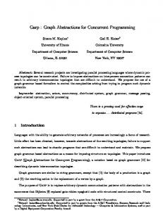
from one model to the next, gradually transforming models and refining the abstract communication in the architecture model down to its bus-functional implementation (Figure 1). The abstraction levels and models at the core of the methodology are defined such that models can be generated automatically through corresponding refinement tools. Refinement tools apply transformations to a model in order to represent and implement design decisions taken from the user or from an automatic synthesis algorithm. With each design step, additional layers of communication functionality are added to the design and inlined into the processing elements for implementation. In the process, channels between PEs abstracting the communication layer are replaced with channels at the next lower level of abstraction. Depending on the specific refinement tools, all or part of each communication layer are taken out of a set of databases or generated on the fly.
Architecture model Architecture model
Model n Model n Synthesis Synthesis Design decisions
Refinement Refinement
Lib Lib
Model n+1 Model n+1
Bus-functional model Bus-functional model
Figure 1: Communication design flow.
1.1
Design Flow
Typically, a system design process in general starts with an executable description of the desired system functionality [1]. Based on the fact that computation and communication in a system are to a large part orthogonal and hence can be separated, we can divide the system design process into two major tasks [4]. First, computation design implements the system computation on an architecture of processing elements (PEs, i.e. software and hardware processors, memories, and IPs). In the resulting architecture model, PEs communicate via message-passing channels. Then, communication design implements this abstract communication between PEs over wires of busses and other communication structures. The result is a bus-functional description of the system as a netlist of PEs connected via pins and wires where each PE can then be further implemented in software or hardware through a backend process. Within this general framework, the communication design methodology is then defined as a set of models and transformations between models that subdivides the communication design flow into smaller, manageable steps. With each step, a new model of the design is generated where a model is a description of the design at a certain level of abstraction, usually captured in machine-readable and executable form, i.e. in a system-level design language (SLDL). The abstraction level of each model is defined by the amount of implementation detail contained in the model, e.g. in terms of structure (space) or order (time), as represented by the interfaces and semantics of the channels connecting PEs. At the start of the design process, communication is described in purely behavioral or functional manner through message-passing channels. At the end of the communication design flow is a structural description of the communication architecture in the form of wires connecting the pins of bus-functional PEs. Communication design is then the process of moving
1.2
SoC Communication
In general, SoC applications require reliable, synchronous and asynchronous communication between entities. In synchronous communication, both sender and receiver are provided with information about the completion of the transaction, i.e. delivery of data from sending to receiving entity. Usually, this means that on both sides calls block until it is guaranteed that data has arrived at/from the other end1 . Around the actual data transfer, this requires synchronization to ensure that both sides have issued and entered matching communication calls and/or that data has been transfered and delivered to the caller successfully. Note that synchronous communication precludes loss of data but does not guarantee protection against date errors, for example. Synchronous communication is often chosen because it minimizes storage and by default, any lossless communication without buffering has to be synchronous and blocking. Asynchronous communication, on the other hand, is less restricted in that no feedback about completion of transfers is provided or required. In the general case, communication calls on both sides do not block on successful data delivery, i.e. communication partners are decoupled and don’t need to be synchronized. Asynchronous communication enables and is a consequence of buffering of data without overall synchronization. Asynchronous communication therefore acts like a FIFO queue where the queue depth depends on the amount of buffering in the actual implementation2 . Note that independent of the blocking and 1 Calls might not block on delivery if data is buffered and some other mechanism (e.g. callbacks) is available to provide feedback about completion. 2 If the implementation does not make any guarantees at all, queues of depth zero are possible which, if lossless, are equivalent to synchronous
2
non-blocking nature of communication in the synchronous and asynchronous case, calls itself may be blocking or nonblocking depending on how overflow of any available local buffers is handled. For example, if data is simply discarded when buffers are full, asynchronous sends are nonblocking but lossy. In both cases, reliable communication has to be lossless and error-free, i.e. it is guaranteed that data that is put in on the sender side will come out unchanged at the receiving end. Reliability is achieved through flow control and/or error correction. Flow control is error prevention in that it ensures that communication partners can not overrun each other, thus avoiding data loss during the actual data transfer. By matching data rates on both ends, including local delays for processing of data, it guarantees that both sides are free to send and receive. Therefore, during a transfer, flow control needs to delay the faster end until it can be made sure that the other side is ready. At the lowest level, flow control requires some appropriate timing guarantees in the implementation, for example by inserting delays or wait states to communicate at a lowest common, fixed data rate. On top of that, information about the state of data processing needs to be exchanged, i.e. making sure that data is available for sending (ready messages) or that the receiver can accept data and has space to put it (acknowledgments), in order to match data rates and delay the faster end by appropriately blocking callers. Note that synchronization for synchronous communication and flow control are related, and the implementation of one can ease or even replace the implementation of the other. For example, state information provided by flow control can be used for synchronization. In fact, flow control is a less restricted version of synchronization of individual data elements, and without buffering they are equivalent. Error correction is necessary to deal with unreliable underlying communication structures. Possible errors can include data (bit) errors or complete loss of data. Typically, error correction requires detection of errors together wit h retransmission of data. Error detection is usually based on (negative or lack of) acknowledgments from receiver to sender together with error checking at the receiving side. Note that error correction can compensate for data loss due to lack of or incomplete flow control. Therefore, if error corrections is necessary for other reasons and if the performance hit can be tolerated (e.g. if the likelihood of overflows is small), it can possibly replace flow control completely. Both flow control and error correction can profit from intermediate buffering of outstanding data in order to increase performance and throughput by hiding and compensating for communication delays and latencies (e.g.
to inject more data while waiting for replies or acknowledgments). Also, intermediate buffers are unavoidable in multi-hop communication architectures that require storeand-forward configurations. However, buffering affects synchronization and flow control, and it requires special handling for their implementation. For example, buffering without additional synchronization results in asynchronous communication by definition, even though communication from buffer to buffer (or between application and buffer) is synchronous. Pairwise synchronization on each leg does not provide end-to-end synchronous communication unless it can be guaranteed that synchronization for the same data in intermediate way-stations happens simultaneously. Otherwise, additional overall synchronization is required to track the data across buffers on its path for synchronous communication. Buffers can be used to even out data rate variations in general and for flow control in particular. Given large enough buffers, explicit flow control can possibly avoided all together as long as burst of data are guaranteed to fit into the buffers. Otherwise, information about buffer fill states needs to be exchanged. In any case, however, flow control at lower levels needs to ensure that communication between buffers matches the rate at which data is read from one buffer with the rate at which it can be stored in the next. Note that in contrast to synchronization, reliability of communication between buffers implies overall endto-end reliability. However, cross-influences between different communication streams due to sharing of resources (e.g. buffers) usually requires end-to-end flow control in order to avoid unnecessary blocking of others and hence, in the worst case, the possibility of deadlocks in case one stream saturates shared resources. All in all, a communication design flow needs to take all these issues into account in order to allow designing an optimal communication architecture for a given SoC application.
1.3
Related Work
There is a wealth of system-level design languages (SLDL) like SpecC or SystemC [1, 2] available for modeling and describing systems at different levels of abstraction. However, the languages itself do not define any details of actual concrete design flows. Recently, SLDLs have been proposed as vehicles for socalled transaction-level modeling (TLM) of systems to provide communication abstraction [3]. However, no general definition of the level of abstraction and the semantics of transactions in such models have been given. Furthermore, TLM proposals so far focus on simulation-purposes only and they lack a path to vertical integration of models for
communication.
3
implementation and synthesis. There are several approaches dealing with automatic generation, synthesis and refinement of communication [6, 5, 7]. None of these approaches, however, provide intermediate models breaking the design gap into smaller steps required for rapid, early exploration of critical design issues. Finally, in [8], the authors show an approach for modeling of communication at different levels of abstraction with automatic translation between levels based on message composition rules. However, they do no propose an actual design methodology and their approach is, for example, limited in its support for arbitration and interrupt handling in traditional bus-based architectures.
Channels at different layers and different channel types in the same layer have different semantics for the transactions performed over them. For example, they can vary in the amount of synchronization or reliability they provide. The services offered by a layer at its interface define certain semantics of transactions in the system where details of lower layers (including the layer itself) are abstracted away. In other words, semantics of transactions vary from layer to layer and specific transaction semantics are defined as the set of services (methods) declared in a layer’s interface (API). Consequently, system communication can be described as transactions on different levels of abstraction corresponding to each layer of communication. Hence, by implementing only higher layers of functionality and abstracting system communication as transactions at the level of a layer’s interface, each layer defines a model of the system at a certain level of abstraction.
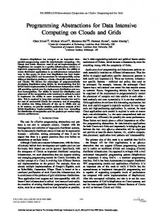
2 Communication Layers The communication design flow is structured along a layering of communication functionality. The implementation of SoC communication is divided into several layers based on separation of concerns, grouping of common functionality, dependencies across layers, and general applicability of design space exploration through humans or automated tools. Layers are stacked on top of each other where a layer provides services to the next higher layer by building upon and using the services provided by the next lower layer. In general, at its interface to higher layers, each layer provides services for establishing communication channels and for performing transactions over those channels. Channels are virtual mechanisms offered by a layer to transport data between end-points created in the layer’s interface (by communication partners in different PEs). They may be stateful or stateless depending on whether their end-points are associated with state in their implementation inside the PEs. Similarly, channels can be connection-oriented or connection-less depending on whether they implement handshaking for channel setup before and/or after data is exchanged. Channels can be pre-defined/hardcoded statically as part of the system configuration or established dynamically during run-time. End-points and hence channels in the system are distinguished by names, i.e. a channel is defined by creating end-points with the same name in the layer’s interface. At the interface to higher layers, logical channels between named end-points are defined and used to exchange data at the level of the layer’s interface. Internally, a layer will implement its channels by mapping each channel to one or more channels in the next lower layer. As a result, a layer inherits the communication functionality of its next lower layer and provides its own, more powerful services on top of that.
PE PE
PE PE App
App
Layer 1
Layer 1
Layer n-1
Layer n-1 Channel n n+1
(a) Input model n PE PE
PE PE App
App
Layer 1
Layer 1
Layer n-1
Layer n-1
Layer n
Layer n Channel n+1
(b) Output model n + 1
Figure 2: Model refinement. With each step in the design flow, an additional layer of communication functionality is introduced into the design model. Therefore, as a result of each design step, a new system model at the next lower level of abstraction is generated. As show in Figure 2, the design is refined stepwise by inlining layers of communication implementation into the design’s PEs and by replacing the communication between PEs (as represented by the channels connecting PEs) with channels that model the transaction semantics behav4
ior at the interface of the next lower layer in an abstract manner. In each model, channels between PEs can generally be described in a purely behavioral manner or as a hierarchical composition of channels from the next lower layer. In the latter case, the hierarchically composed channel specifies how its layer is implemented on top of the services provided by the next lower layer. Model refinement is then the process of refining the channels in such a way and inlining the functionality of the outer channel into the PEs, exposing its subchannels in the process. Depending on the type of PE, communication layers will be realized in different form (software, operating system kernel, device driver, hardware abstraction layer (HAL), hardware) through the backend tools that take each PE down to its cycle-accurate implementation. Note that layers of communication in the system model as a result of this communication design flow serve as a specification of the desired behavior for implementation in the backend tools. Therefore, as part of synthesis of communication in hardware and/or software in the backend, layers are possibly grouped or merged for optimizations across layer boundaries.
2.1
chronization in one layer is to provide synchronous communication on top of underlying asynchronous transactions. Table 1 summarizes the layers for SoC communication by listing for each layer its interface of services offered to the layer above, its functionality, and its level of implementation in the PEs. The ISO OSI reference model [9] was consulted as an initial general guideline for developing the layers and corresponding OSI layers are noted for each SoC communication layer. Note, however, that due to the unique features and characteristics of SoC communication, layers have been tailored specifically to these requirements. As a result, layering of SoC communication functionality deviates from the OSI layers defined for classical, general-purpose computer networking. Compared to the OSI model, layers have been split or combined to satisfy these needs, especially for support of traditional bus-based communication at the lower levels [10]. In the following, we will describe and define each layer in more detail: Application Layer The application layer corresponds to the computation functionality of the system which defines the behavior of the application implemented by the system design. During the computation design process, the initial specification of the desired system behavior has been mapped onto a set of PEs. Inside each PE, the parts of the initial specification mapped onto that PE form the PE’s application layer. The application layers describe the processing of data in the PEs. PEs exchange data by passing messages over named channels with synchronous or asynchronous semantics where channels with different names are used to distinguish among data of different purpose.
Layers for SoC Communication
As outlined in Section 1.2, the SoC communication design flow supports implementation of reliable synchronous and asynchronous communication channels found in the application. Implementation of synchronous communication provides the corresponding guarantees about completion of transactions. For asynchronous communication, no such feedback is made available. In fact, neither are any guarantees about buffer sizes made in that case and asynchronous communication might even end up being implemented in a synchronous form. If a defined amount of buffering is required, queues of appropriate depth need to be implemented as part of the application. Communication layering is based on separation and chaining of implementation issues like synchronization, reliability (flow control, error correction), sharing/multiplexing (requiring separation in time and space, e.g. arbitration and addressing), and partitioning (bridging, routing). Depending on the amount of communication functionality implemented, communication semantics vary from layer to layer in whether transactions are synchronous/asynchronous or reliable/unreliable. For example, implementation of a communication aspect in a layer might affect semantics, resulting in communication that is asynchronous instead of synchronous or unreliable instead of reliable, e.g. due to unavoidable buffering in bridges. Layers then need to be added above to compensate for these side effects. For example, the purpose of implementation of syn-
Presentation Layer The presentation layer provides services to establish named channels between PEs and to reliably send and receive messages of arbitrary, abstract data type over them. Each presentation layer channel carries messages of a fixed type where a sequence of messages of the same type can be transfered repeatedly over a named channel. In general, the presentation layer provides synchronous and asynchronous channels depending on the application requirements. The presentation layer becomes part of the application software and is responsible for data formatting. It converts abstract data types in the application to blocks of ordered bytes as defined by the canonical byte layout requirements of the lower (network) layers. For example, the presentation layer takes care of PE-specific data type conversions and endianess (byte order) issues. 5
Layer Application Presentation Session Transport Network Link Stream Media Access Protocol Physical
Interface semantics N/A PE-to-PE, typed, named messages • v1.send(struct myData) PE-to-PE, untyped, named messages • v1.send(void*, unsigned len)
Functionality • Computation
Impl. Application
OSI 7
Application
6
OS kernel
5
OS kernel
4
• Routing
OS kernel
3
• Station typing • Synchronization
Driver
2b
• Multiplexing • Addressing
Driver
2b
• Data slicing • Arbitration
HAL
2a
• Protocol timing
Hardware
2a
• Driving, sampling
Interconnect
1
• Data formatting • • • • •
PE-to-PE streams of untyped messages • strm1.send(void*, unsigned len) PE-to-PE streams of packets • strm1.send(struct Packet) Station-to-station logical links • link1.send(void*, unsigned len) Station-to-station control and data streams • ctrl1.receive() • data1.write(void*, unsigned len) Shared medium byte streams • bus.write(int addr, void*, unsigned len) Unregulated word/frame media transmission • bus.writeWord(bit[] addr, bit[] data) Pins, wires • A.drive(0) • D.sample()
Synchronization Multiplexing Packeting Flow control Error correction
Table 1: Communication layers. Session Layer The session layer provides named channels over which untyped messages can be transfered reliably. Session layer messages are uninterpreted, ordered blocks of bytes. Session layer channels are used to distinguish among communication end-points in the system application where each channel can carry an ordered sequence of messages. Channels are synchronous or asynchronous and the session layer generally supports both types of channels.
single stream (i.e. separating them in space; it does not necessarily implement separation in time in those cases and messages can enter the target stream concurrently). Transport Layer The transport layer provides services to reliably transmit end-to-end streams of arbitrary, untyped messages (blocks of bytes). Channels at the transport layer define the communication pipes between PEs in the system over which individual communication sessions are handled by the layers above. Transport layer channels are generally asynchronous where the amount of buffering, if any (i.e. possibly providing synchronous communication), generally also depends on the layers below.
The session layer is at the interface between application software and operating system. If the layers below are asynchronous, the session layer will implement end-to-end synchronization to provide any synchronous communication required above. Furthermore, it is responsible for multiplexing messages of different channels into a number of end-to-end sequential message streams. Messages of different channels at the session layer interface inside a single PE are usually statically or dynamically ordered. If all communicating PEs transmit messages of different session layer channels in a pre-defined order, they can be merged into a single stream directly. In general, however, the session layer merges channels into multiple concurrent streams or it implements name resolution for multiplexing arbitrary messages over a
The transport layer implements end-to-end data flow as part of the operating system kernel. It splits messages into smaller packets, e.g. to reduce intermediate minimum buffer sizes from whole messages down to single packets. Depending on the links and stations in lower layers, the transport layer implements endto-end flow control and error correction to guarantee reliable transmission. Network Layer The network layer provides services for establishing end-to-end paths that can carry streams 6
of packets. Depending on the layers below, the network layer may or may not guarantee reliable delivery but in the general case, transactions are best-effort only. Furthermore, channels are asynchronous depending on both the layers below and the amount of buffering introduced in the network layer itself.
Stream Layer The stream layer provides separate streams for transporting control and data messages from station to station. Data messages are arbitrary, uninterpreted byte blocks. The format of supported control messages, if any, is dependent on specific layer implementations (e.g. simple handshaking in the case of interrupt-driven synchronization). Stream channels are generally asynchronous and unreliable. Reliability of streams may depend on certain assumptions, e.g. streams might guarantee reliability (or at least no data loss) with proper prior outside synchronization.
The network layer completes the high-level, end-toend communication implementation in the operating system kernel. It is responsible for routing of endto-end paths over individual point-to-point links. As part of the network layer implementation, additional communication stations (transducers) with intermediate buffering are introduced as necessary, e.g. to create and bridge subnets, splitting the system of connected PEs into smaller, directly connected groups. Assuming reliable stations and links, routing in SoCs is usually done statically, i.e. all packets of a channel take the same fixed, pre-determined path through the system. In general, however, the network layer can implement dynamic routing on a connection or packet-by-packet basis to deal with changing underlying conditions. In all cases, the network layer is responsible for separating different end-to-end paths going through the same stations. In a simple implementation, a dedicated logical link is established between two stations for each channel routed through them, assuming the underlying layers support a large enough number of simultaneous logical links between all pairs of stations. In the general case, multiple connections are routed and multiplexed over a single logical link and the network layer implements additional addressing to distinguish different end-to-end connections.
The stream layer is the bottom part of peripheralspecific drivers in the operating system. It is responsible for merging and implementing multiple control and data streams over a common, shared medium. As such, it multiplexes and de-multiplexes streams, e.g. by separating them in space (but not time) through addressing. Note that since control streams might require very specific access formats, merging through simple appending of addresses to control messages might not be possible and other schemes like polling might be required, for example in the case of interrupt sharing. Media Access Layer The media access layer provides services to transfer blocks of bytes over channels representing shared media between stations. Depending on the type of medium, different categories of transactions or different categories of information within a transaction might be supported by a channel (e.g. distinction of address, control, and data). In general, a medium is asynchronous and unreliable. It usually requires prior outside synchronization to avoid data loss. Furthermore, a medium mar or may not be errorfree.
Link Layer The link layer provides services to establish logical links between adjacent (directly connected) stations and to exchange data packets in the form of uninterpreted byte blocks over those links. Depending on the lower layers, a number of named logical link channels can be established between pairs of stations. Furthermore, links may or may not be reliable and synchronous.
The media access layer implements the hardware abstraction layer for a station’s external interfaces. It is responsible for slicing blocks of bytes into unit transfers available at the interface. In the process, it’s implementation has to guarantee that the rates of successive transfers within a block match for all communication partners. Furthermore, the media access layer regulates and separates simultaneous accesses in time (e.g. through arbitration). Depending on the scheme chosen, additional arbitration stations are introduced into the system as part of the media access layer.
The link layer is the highest layer of drivers for external interfaces and peripherals in the operating system, and it provides their interface to the rest of the OS kernel. The link layer defines the type of a station (e.g. master/slave) for each of its incoming or outgoing links. As a result, it implements any necessary synchronization between stations, e.g. by splitting each logical link into separate control (e.g. interrupts or acknowledgments) and data streams as provided by lower layers.
Protocol Layer The protocol layer provides services to transfer words or frames (i.e. groups of bits) over a physical medium. Depending on the transfer modes supported by the medium, different types of transactions, e.g. for different word sizes might be available. A protocol layer channel is asynchronous, un7
buffered, lossy, and it may or may not be error-free. Since there is no buffering, it requires proper outside synchronization to provide lossless communication or any communication at all.
ing the specific target communication architecture for implementation such that the stack is optimized to application requirements and physical characteristics. As the design process moves from top to bottom layer by layer, only the functionality required by the application is gradually implemented. Each layer implements its part of the requirements and thereby defines the specification for the next layer as the functionality remaining. However, in order to implement higher layers efficiently and optimally, information about basic characteristics of the underlying layers needs to be available even in this case. For example, error correction at higher layers depends on whether individual links are reliable or not.
The protocol layer is the implementation of the medium’s transfer protocol in the hardware of a station’s interface. It is responsible for driving and sampling the external pins according to the protocol timing diagrams and thereby matching the transmission timing on the sender and receiver sides. As part of the protocol layer, any repeater stations that connect physical wire segments with matching protocols in order to represent them as one common medium are introduced as necessary.
In typical, traditional bus-based SoC communication architectures, individual point-to-point links are assumed to be reliable with low latencies. Therefore, no error correction is required and point-to-point bus transactions are usually implemented synchronously without buffering. Networks of busses with bus bridges in between are required to deal with incompatible bus protocols of IPs, or for performance or other optimization reasons. In these cases, buffering in the bridges generally requires end-to-end flow control in higher layers, especially if resources are shared. Furthermore, end-to-end synchronization across bridges has to be added in the topmost layers if required by the application. Finally, the application itself will implement any additional deep buffering to avoid unnecessary blocking in case of data rate variations.
Physical Layer The physical layer provides services for writing to (driving) and reading from (sampling) channels representing the wires connecting stations. It implements the physical aspects of communication as the interface between digital hardware and the analog real world. It is responsible for applying the proper signals to the pins of a station’s external interface such that the signal can be recognized and reconstructed at the other side.
2.2
Communication Layer Stacks
In general, when implementing a specific stack of communication layers for a SoC design, implementations of individual layers are dependent on each other. For example, the implementation of higher layers depends on guarantees and services provided by lower ones. On the other hand, the specification for implementation of lower layers is derived from the requirements of higher ones. Therefore, whole stacks of communication layers are traditionally designed together at once. For example, in general-purpose networking standards where communication stacks have to support a wide variety of applications with dynamically varying characteristics on top of any possible physical medium, whole layer stacks are designed with the most general assumptions about requirements and guarantees. Physical media are generally assumed to be best-effort only, i.e. lossy and error-prone, requiring error correction at higher layers. On the other hand, to support both varying application requirements and unknown, long media latencies in an efficient way, heavy buffering is employed. The required end-to-end flow control is then performed together with end-to-end error handling in the upper layers. As a result of buffering, communication is usually asynchronous only and synchronization is added in the topmost layers if necessary. In SoCs, on the other hand, where the application is known a-priori, layers can be designed together with defin-
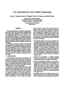
An example of communication layers for a typical SoC communication architecture is shown in Figure 3. The example shows a part of a system with two processing elements PE0 and PE1. At the application level, PE0 communicates with PE1 through two message channels, c1 and c2. Furthermore, PE1 exchanges data with another remote PE in the system through a channel c3. In the presentation layer, abstract data types in the messages are converted into canonical byte format in both PEs. In the session layer, messages from c1 and c2 are merged into a single data stream between PE0 and PE1. The transport layer splits large messages into streams of packets in order to have uniform, smaller message sizes for buffering at lower layers. In the network layer, the network architecture of stations and links is decided upon and packets are routed accordingly. In this example, PE0 and PE1 are directly connected via a single logical link whereas PE1 sends and receives data destined or originating from other PEs through a logical link to a network interface which in turn will route the data packets to/from the other PEs via its outgoing logical link(s). For both links between PE0 and PE1 and between PE1 and the interface, bus-based communication is used and PE1 is declared the master whereas PE0 and the interface 8
PE0
Repeater
PE1
Interface
c1 c2
Application
c3
Presentation Session Transport Network Link Stream Media Access Protocol
Interrupt0
Interrupt0
Interrupt1
Bus0
Bus1 Arbitration bus
Medium
Figure 3: Communication architecture example. act as slaves. Correspondingly, links are split into control and data streams in the link layer where control streams perform handshaking from slave to master and data streams perform transfers under the control of the master. In the stream layer, the two data streams in PE1 are then multiplexed over the single medium the PE is connected to by assigning different addresses to each stream. In the media access layer, data stream packets are sliced into bus words. Furthermore, inside the bus master PE1 media access layer, arbitration calls to request and release the bus are inserted before and after each bus transfer. For the link between PE0 and PE1, the bus is split into two segments and a repeater is inserted as part of the media access layer in order to cope with slight variations in PE0’s and PE1’s bus protocols. The repeater connects the different bus protocols and passes bus words and handshake events transparently between them. Note, however, that the necessary buffering of words and events in the repeater will have the effect of increased latencies. Finally, the protocol layer implements the protocols for driving and sampling the wires of Bus0 connecting PE0 and repeater, and for Bus1 connecting repeater, PE1, and the interface. The protocol layer also implements handshaking in the form of interrupts between stations and the protocol for bus requests over the arbitration bus in PE1. The links to other PEs in the system going in and out of the interface are implemented over a shared, longlatency, error-prone network medium. The link layer implements buffering, error correction and flow control to provide high-performance, reliable link communication by interleaving data and control over a single mixed byte stream supported by the medium. The stream layer assigns
medium addresses to each link and the media access layer then splits packets into media frames while participating in the arbitration protocol on the medium (e.g. through collision detection). Finally, the protocol layer converts the media frames into bit streams on the physical wires, including any special services required for arbitration (e.g. listen-while-send).
3 Communication Models A system model is generally a description of the system at a certain level of abstraction, i.e. with a certain amount of implementation detail. As outlined in the previous section, during the design process, layers of communication functionality are gradually inserted into the system design model. With each step, a new layer of detail is added to each PE (possibly introducing new components in the process) and the channels between PEs are replaced with channels at the level of abstraction of the next lower layer’s interface. Therefore, with each design step, the system model is refined and a new type of model is generated. As a result, there are generally as many system models as there are communication layers. In all but the lowest, physical model, communication is described in an abstract, functional manner as transactions over channels. Depending on the layer and hence the model, channels support transactions with semantics at different levels of abstraction but in all cases communication is behavioral. Only at the lowest level, communication in the physical model is fully structural as a netlist of stations connected by models of actual wires. 9
CF OS is empty. The encoder on the DSP is assisted by a custom hardware coprocessor (HW) for the codebook search. Furthermore, four custom hardware I/O processors perform buffering and framing of the vocoder speech and bit streams. In the PE architecture model, processing elements communicate via message-passing channels. The communication design process gradually implements these channels and generates a new model for each layer of communication functionality inserted. In the following sections, we will describe and define the different communication models that correspond to the different communication layers.
A so-called transaction-level model (TLM) in general is a model of a system in which communication between components is described in a behavioral or functional view (i.e. components communicating via channels), not in a structural view (i.e. netlist of components connected via wires). All the intermediate models in the communication design flow are TLMs with transaction semantics at different levels of detail. Depending on the amount of detail needed, each model presents a different view of the system for different purposes.
3.1
System Modeling Example
In the following, we will use an example of a system design to describe and define the different models corresponding to the layers at the core of the communication design process. The design being used as an example is a mobile phone application stripped down to two typical functional blocks. The specification model of the design example is shown in Figure 4. At the top level, it consists of concurrent functional blocks for JPEG encoding of digital pictures and for voice encoding/decoding (vocoder) on the transmission path to the base station. A channel between the two blocks is used to send control messages from the JPEG encoder to the vocoder. The JPEG encoder [11, 12] is triggered by an external signal. After initialization, stripes of raw pixels are received from the external camera and encoded in blocks of 8x8 pixels in a fourstage pipeline. The voice encoder/decoder [13, 14], on the other hand, internally runs encoding and decoding blocks in parallel. On the encoding side, voice samples from the microphone are split into frames of 160 samples (20 ms of speech) and further into subframes of 40 samples for encoding into 244 bits per frame. On the decoding side, the bit stream received from the radio is used to synthesize frames of speech in a reverse process. The system model for the example after computation design is shown in Figure 5. During computation design, the application has been mapped onto a typical mobile phone baseband platform consisting of subsystems for digital signal processing (DSP) and basic control. On the controller side, a ColdFire processor is running the JPEG encoder in software assisted by a hardware IP component for DCT (DCT IP). Under the control of the processor, a DMA component receives pixel stripes from the camera and puts them in a shared memory (Mem) where they are then read by the processor. On the DSP side, the DSP processor is running encoding and decoding tasks in parallel. Tasks are dynamically scheduled under the control of an operating system model [15] that sits in an additional OS layer DSP OS of the DSP processor. Note that on the ColdFire side, no operating system is needed and the OS layer
3.1.1
Application Model
The application or presentation model for the design example is shown in Figure 6. The application model is the starting point for communication design and is mostly equivalent to the architecture model that was the result of the computation design process. However, as required for the communication design flow, the purely behavioral DCT IP component has been replaced with a model that encapsulates a structural (bus-functional) model of the component in a wrapper (DCTAdapter) that implements all layers of communication with the IP. Since the IP’s communication protocols are pre-defined and fixed, its communication can not be designed arbitrarily and the wrapper provides the necessary functionality to be gradually inserted into the IP’s communication partners as design progresses. The application model specifies the communication functionality to implement. For each data item (variable) communicated between PEs, the model contains a corresponding typed message-passing channel. Communication and channels at the application level are always reliable. In this example, all channels between PEs are specified to be asynchronous, i.e. the application does not require synchronous messages. In general, channels at the application level specify the synchronization requirements but not the amount of buffering for implementation of the channels. Instead, the amount of buffering in application-level channels will depend on their implementation in lower layers. In the application model, channels can therefore have any amount of buffering, e.g. some average, fixed number or, if information about the implementation is available, they can be annotated with estimated buffer sizes for feedback during simulation. In the application model, the shared memory PE is modeled as a special channel. The memory channel encapsulates all data items (variables) mapped into the shared memory component. At its interface, the memory channel provides two methods for each data item to read and write the item’s value from/to memory. 10
Pixel
Control
Radio
Vocoder
Ctrl
11
Figure 4: System design example specification model.
JPEG JPEGInit
Voice
SpchIn
SerIn
inframe[160] inparm[244]
Coder
JPEGStart
Decoder DefaultHuffman HfmDc
Pre_Decoder
Pre_Process
Lp_Analysis
HfmDC
Open_Loop
Decode_Lsp
ACEHuff
JPEGHeader
JPEGEncode ReceiveData stripe[]
HandleData
mduWide = 1..Width DCT Quantization
Codebook
Post_Filter
Update
Post_Decoder Huffman
outframe[160]
JPEGEnd
Closed_Loop
Decoder_ Subframe
mduHigh = 1..Height
EncodeStripe
Subframes
DCEHuff
SpchOut
Post_Process
outparm[244]
SerOut
Disk
Voice
Radio
DMA
BI DSP_OS
RcvPara
12
imgSize
stripeLen
Figure 5: System design example PE architecture model.
SI
DSP
ColdFire
SndPara
Coder
JPEGInit ACEHuff
SpchIn
inframe
Ctrl
CF_OS
ReceiveData
Mem
SerIn
inparm
DCEHuff
JPEGEncode
Pre_Process
Decoder Pre_Decoder
Lp_Anal
Dec_Lsp
Open_Lp
exc[40]
stripe[]
SndRcvPara
HW
T0
Cdbk_Start Subframes
Decoder_ Subframe
EncodeStripe HandleData
Post_Filter
HData
SendHData
Post_Decoder
DData
RecvDData
Closed_Lp
Codebook
Cdbk_Start Cdbk_End
Cdbk_Start prm[10]
Update
gain
Quantization Post_Process
Huffman
DCT
BO
OSModel JPEGEnd
DCT_IP
outframe
SerOut
SO outparm
SpchOut
DMA
BI DSP_OS
RcvPara
imgSize
Coder
JPEGInit ACEHuff
DCEHuff
JPEGEncode
Pre_Process
Decoder Pre_Decoder
Lp_Anal
Dec_Lsp
Open_Lp
exc[40]
SndRcvPara
Cdbk_Start Subframes
Decoder_ Subframe
EncodeStripe HandleData
Post_Filter
SendHData
Post_Decoder
RecvDData
Codebook
Cdbk_Start Cdbk_End
Cdbk_Start prm[10]
Update
gain Post_Process
strm
Huffman
mac dctProtocol
Closed_Lp
Quantization
link
HW
T0
stripe[]
DCTAdapter
13
Figure 6: Application model.
stripeLen
SI
DSP
ColdFire
SndPara
SpchIn
inframe
Ctrl
CF_OS
ReceiveData
Mem
SerIn
inparm
int
BO
OSModel JPEGEnd
outframe
DCT
SerOut
SO outparm
DCT_IP
SpchOut
transBI
inparm
BI
BI_HW
transBri
imgSize
S
stripeLen stripe S
transDMA
DMA_HW
DSP_OS
inframe
SI
SI_HW
imgSize
exc[40] inframe inparm T0
exc[40]
Mem
stripe
T0 prm[10]
HData DData
transHW
outframe
prm[10]
gain
HW_HW
14
Figure 7: Transport model.
ctrl stripeLen
DCTAdapter
transSI
DSP
M
char[]
M
DMA
outparm
ColdFire
strm
CF_OS
mac dctProtocol
int
gain
HW
OSModel DCT
transBO
outparm
BO
BO_HW
DCT_IP
transSO
outframe
SO
SO_HW
3.1.2
Transport Model
tion between the same end-points is sequential. Therefore, no concurrent communication can be multiplexed over the same transport stream (sequential communication, on the other hand, is merged over single streams as much as possible in order to reduce the number of transport streams in the system). Therefore, each transport will only carry messages that are already sequentialized (ordered in time) by the application. Since ordered messages going over the same transport can be multiplexed directly, merging of sessions over transports is resolved simply through proper connectivity in the operating system layer of PEs (for hardware PEs that don’t have an OS layer, an extra hardware layer that will absorb all further communication implementation is inserted).
The transport model of the design example is shown in Figure 7. Inside each PE, the model contains implementations of the presentation and session layers. As will be explained below, in this example, the session layer is empty. Note that in the general case of systems with session layer functionality, an additional intermediate session model of the system would be available. In the transport model, PEs are connected through transport channels that carry streams of untyped (byte-level) messages. In general, channels in the transport model are always reliable. However, the transport model does not specify the amount of synchronization and buffering in its channels, i.e. channels are generally asynchronous and can have any amount of buffering. On the other hand, if their implementation is known or can be estimated, semantics of channels in the transport model can be selected to reflect and abstract the behavior of their implementation. Inside the PEs, the model contains presentation layer implementations in the form of adapter channels that provide the presentation layer API to the application on the one side while connecting and calling transport layer methods on the other side. As outlined in previous sections, the presentation layer performs data formatting for every message data type found in the application. Therefore, for each application layer channel there are corresponding presentation layer adapters inside the PEs that convert the abstract data types into byte blocks. Since the presentation layer becomes part of the application, its adapter channels are instantiated inside each PE’s application layer. Note that for the IP component, presentation layer adapters were part of the IP wrapper and have been inlined into the PE (ColdFire) communicating with the IP. As part of the presentation layer implementation, the shared memory PE model has been refined down to an accurate representation of the byte layout in the memory. All variables stored inside the memory are replaced with and grouped into a single array of bytes. As part of the presentation layer, layout and addressing of variables inside the memory is defined based on the parameters (e.g. alignment) of the chosen target memory component. Instead of accesses to individual variables, the memory PE in the session or transport model only supports read and write accesses to blocks of bytes at a given offset in the memory. The presentation layers inside the PEs accessing the memory are in turn responsible for converting application variables into size and offset for shared memory accesses. The transport model generally also contains session layer implementations inside the PEs. In this case, the application only requires asynchronous communication and the session layer does not need to implement any extra end-to-end synchronization. Furthermore, all communica-
3.1.3
Link Model
Figure 8 shows the link model for the system design example. In this design, both the transport and network layers are empty, i.e. there are no additional layers implemented in the PEs of the link model. Furthermore, the intermediate network model which would generally be available is equivalent to the transport model and therefore not shown here. The transport layer is empty for this example because message sizes are small and deterministic such that extra packeting of messages is not necessary. In addition, the implementation of lower layers is known to provide reliable communication without sharing of resources (buffers), i.e. no end-to-end flow control or error correction is needed. The network layer, on the other hand, is not required in this design since all data is routed statically in a pre-determined manner, i.e. the routing of the network layer can be modeled through proper static connectivity of link level channels. In the link model, end-to-end channels have been replaced with point-to-point logical links between adjacent stations that will later be physically directly connected through wires. Since it will be impossible to directly connect the two processors in this example, an additional Bridge station has been inserted into the link model, connecting the two subsystems. As a result, the end-to-end channel between ColdFire and DSP processors has been split into two links. The bridge in between then transparently forwards packets between the two links. In general, channels representing the logical links between stations in the link model may or may not be reliable, synchronous, and buffered, i.e. the link model does not specify how links should be implemented. Again, if information about their implementation is available, on the other hand, link channels can be chosen to model their actual, real behavior for feedback, e.g. during simulation. In the case of this example, all logical links in the design are known to be synchronous, reliable, and unbuffered and the 15
linkBI
inparm
BI linkBri
imgSize
BI_HW
linkBri S
stripeLen
Bridge
stripe S
linkDMA
DMA_HW
DSP_OS
inframe
SI
SI_HW
imgSize
exc[40] inframe inparm T0
exc[40]
Mem
stripe
T0 prm[10]
HData DData
linkHW
outframe
prm[10]
gain
HW_HW
16
Figure 8: Link model.
ctrl stripeLen
DCTAdapter
linkSI
DSP
M
char[]
M
DMA
outparm
ColdFire
strm
CF_OS
mac dctProtocol
int
gain
HW
OSModel DCT
linkBO
outparm
BO
BO_HW
DCT_IP
linkSO
outframe
SO
SO_HW
model contains channels with corresponding semantics. 3.1.4
3.1.5
Media Access Model
The media access model for the design example is shown in Figure 10. In the media access model, stations are connected through channels representing the underlying shared communication media. Media channels support transactions for exchanging data packets in the form of uninterpreted blocks of bytes. Due to the shared nature of normal media, media channels usually allow multiple virtual multi-point connections over them that can occur concurrently, simultaneously and overlapping in time. In general, media channels are asynchronous and they may or may not be reliable and buffered. However, media channels reflect and model the underlying communication medium and the semantics and exact format of the transactions they support therefore depend on the behavior and capabilities of the chosen medium. In this example, there are two busses, cfBus for the ColdFire subsystem and dspBus for the DSP subsystem. Reflecting the master/slave behavior of bus-based communication, both media channels are unbuffered, error-free, and asynchronous on the master side and synchronous on the slave side. Note that bus media channels are not reliable as packets can be lost if the slave is not waiting when the master initiates a transaction. Both busses support multiple concurrent and overlapping virtual connections through addressing. Therefore, for each transaction, the bus address of the virtual connection it belongs to needs to be supplied to the bus channels. For communication with shared memory components, the interfaces of the media channels supports special split transactions that allow the memory component to listen on the medium for a range of addresses and then serve the transaction request after proper address decoding. Since in general and in this example, the medium for communication with an IP component is proprietary and not 100% compatible with other general media in the system (as signified by different semantics and/or different media interfaces), additional transducer stations that translate between different media interfaces have to be inserted in front of each IP in the media access model. In this example, transducer T DCT performs the necessary address translations between cfBus and dctBus. The media access model adds implementations of the stream layer for control and data streams inside each station. For each data stream, adapter channels with implementations of its stream layer are inserted into the corresponding PEs and connected to the proper interface of the media channel, e.g. to the master or slave side of the medium. The data stream layers implement multiplexing of data streams over a shared medium. In this example, multiple data streams over the same medium are separated through proper bus addressing where bus addresses are
Stream Model
Figure 9 shows the stream model for the design example. Implementations of the link layer in the form of adapter channels have been inserted into the PEs for each logical link in the design. Since the link layer is part of the operating system kernel, its implementation channels are inserted into the OS layers of the PEs (or the communication hardware layer for synthesizable PEs). The link layer defines the types of each station and splits the packet streams into separate control and data streams as necessary. In this example, bus-based communication is chosen for implementation and the ColdFire and DSP processors are masters on their respective busses. Furthermore, the DMA component can act as both a master (for communication with the memory) or slave (for communication with the processor) on the ColdFire bus. All other PEs are bus slaves. Since communication with the DCT IP component is compatible with this master/slave arrangement of stations, the corresponding link layer implementation could simply be taken from the IP wrapper and inlined into the CF OS model as link layer adapter channel. Corresponding to the bus-based master/slave arrangement of the example, each logical link has been split into a data stream under the control of the master and a control stream from slave to master. By synchronizing master to slave through the control stream before a packet transfer can be initiated by the master, packet losses are avoided and reliable, unbuffered, and synchronous links are implemented. Channels for data streams have special semantics in the sense that they are synchronous and blocking on the slave side and asynchronous and non-blocking on the master side. Even though they are error-free, they are not reliable as packet losses can happen if transactions are not properly synchronized beforehand. Control channels, on the other hand, are simple handshake channels (queues of depth one for control messages that do not carry values). In general, semantics of channels in the stream model depend completely on the chosen implementation scheme and no general format can be defined. In case of the shared memory PE, since the Mem component is assumed to be always ready, no extra synchronization through control streams is necessary. Instead, a single data stream for memory slave accesses under the control of bus masters is sufficient. In contrast to normal message data streams, the memory data stream carries extra information about the offset of the byte block being accesses in each read or write transaction. Note that in the process of explicitly modeling memory data streams, the memory model has been refined into an active component listening and serving request that come in over its data stream. 17
link
link
link
link
S
M
syncBri
strmBri
inparm
BI
syncBI
M
S
S
M
imgSize
strmBri
strmBI
BI_HW
syncBri S
Bridge
stripeLen
inframe
SI
syncSI lCtrl
syncDMA
strmSI
S
M
DSP_OS DSP
M
SI_HW
ctrl stripeLen
Mem
imgSize
lSI
lBri
shm
exc[40]
inframe inparm exc[40]
outframe
lHW
syncHW
gain
mac int
lBO
CF_OS
prm[10]
gain
HW
lSO
S
M
strmBO
link
OSModel DCT
outparm
BO
syncBO
DCT_IP
BO_HW
syncSO
S
M
strmSO
link
DCTAdapter
outparm
ColdFire dctProtocol
link
HW_HW
lDCT
prm[10]
HData DData
T0
strmHW
S
T0
stripe
M
18
Figure 9: Stream model.
char[]
lDMA
lBI
Mem_HW
M
DMA_HW
strmDMA
S
DMA
link
stripe
outframe
SO
SO_HW
link
strm ADDR
link
strm
link
link
strm BI SI
ADDR
Ctrl
lCtrl lBI
SI_HW
ADDR
T0
gain
HW
strm ADDR
link
outparm
BO
ADDR
strm
ADDR
sSO sBO sHW sSI sBI sCtrl iSO
iBO
iHW
iBI
iSI
OSModel
prm[10]
SO
lSO
BO
lBO
DData
ColdFire
link
dspBus
outparm
iCtrl
lDCT sBri
sDMA sDCT
DCT
outframe
HData
prm[10] gain
exc[40]
BO_HW
link
T0
stripe
HW
imgSize
lHW
exc[40]
strm
inframe inparm
HW_HW
lBri
Bri DMA
stripeLen
int
T_HW
ADDR
dctBus dctProtocol
ctrl
shm
shm ADDR
Mem
inframe
SI
CF_OS
cfBusMaster
dspBusSlave
char[]
lSI
DSP
lDMA
Mem_HW
DSP_OS
dspBusMaster
19
Figure 10: Media access model.
DMA_HW
cfBusSlave
cfBus
ADDR shm
DMA
DCT_IP
BI_HW
Bridge
stripe
DCT
inparm
BI
strm
link
stripeLen
DR
imgSize
D
strm
DR
A
AD
outframe
SO
SO_HW
hardcoded when instantiating the data stream adapters. Implementation of the stream layer of control streams in the media access model generally depends on the underlying medium. For example, control streams can be implemented through normal or specialized media channel transactions. In the example of bus-based communication shown here, control streams are implemented through processor interrupts. For each control stream coming into the master processor, the processor’s OS layer exports a method that implements the corresponding handshaking control transaction. Slave PEs then simply call the corresponding master method as they did with the control channel before. Inside the processors, control handlers then implement the handshaking through semaphores that connect to and signal the processor’s link layer as the control channel did before. In case the processor is not running an operating system (as is the case with the ColdFire processor, for example), handshaking semaphores are implemented by polling a flag set by the control handler whenever an interrupt occurs, suspending the main application in between. In case the processor is running an operating system (DSP), handshaking through semaphores has to be under the control of the operating system and control handlers therefore spawn special tasks that serve as the bottom halves of the control handlers and implement the actual signaling of the semaphores on top of the OS model. 3.1.6
transfers with 32-bit addresses in case of the cfProtocol. Since the media access layer does not implement any additional functionality, transaction semantics of protocol channels and media channels in the media access model are equivalent. Generally, protocol channels are asynchronous and may or may not be reliable and buffered. Their actual semantics and transaction format, however, are directly dependent on and a direct reflection of the behavior and capabilities of the protocol they represent. In the case of the example, bus protocols are asynchronous on the master side, synchronous on the slave side, error-free but not reliable against data loss (in case of not properly synchronized transfers), and they support multiple virtual connections via bus addressing. For shared memory transfers, protocol channels provide split transactions that allow the shared memory to listen to and serve incoming accesses. Furthermore, media access layer implementations differ for normal message-passing transfers and memory transfers. In case of messagepassing transfers, virtual protocol connections are only needed to distinguish different message streams and the same protocol address can be used for all successive transfers in a message packet. For memory accesses, however, protocol addresses have to be used to distinguish among individual addressable units (words) in the memory and addresses have to be incremented properly according to alignment for all successive transfers in a consecutive block of data. Therefore, depending on the type of access, different types of media access adapter channels can be instantiated in a station for each type of media connection. In contrast to media channels, protocol channels only support one active transaction at any given time, even when coming from different virtual connections. Therefore, in addition to slicing of data packets into protocol units, the media access layer implementations in the protocol model also implement contention resolution according to the media’s access protocol in order to regulate conflicting accesses to the protocol channel. In case of bus-based communication as in the example, contention can happen if multiple masters are accessing the same bus. Since both DMA and ColdFire are masters on the cfProtocol, their media access layer adapters implement bus arbitration before each transfer by connecting to and communicating via an additional arbitration protocol channel Arbiter. The arbitration channel provides methods to acquire and release bus access, and its model of arbitration behavior is provided in the form of semaphore semantics. As part of the media access layer implementation in the protocol model, handshaking from slaves to masters through control handlers exported by the processors is refined down to the level of actual hardware interrupts available in the processors. The hardware abstraction layers
Protocol Model
The protocol model of the design example is shown in Figure 11. The protocol model includes implementations of the media access layer in the form of adapter channels in all stations connected to a medium. For each media connection in a station, a corresponding media access adapter of the right type (e.g. master or slave access) is instantiated. For the software processors, the media access layer becomes part of the processor’s hardware abstraction layer (HAL) and corresponding processor layers CF HAL and DSP HAL that instantiate the media access layer adapters are inserted for the ColdFire and DSP processors, respectively. In the protocol model, media channels have been replaced with shared protocol channels connecting the stations. Protocol channels model and provide all the possible transactions supported over the actual physical medium. The media access layers then use the different services and transfer models available in the protocol to efficiently implement media transfers, slicing data packets into actual data transfer units (words or frames) supported by the protocol on the physical medium. In the case of the example shown here, bus protocols support transactions for transfers of standard 24-bit bus words with 16-bit addresses in case of the dspProtocol or for byte, word, and long-word 20
link
mac
ADDR
mac
link
mac
POLL_ADDR
inframe
SI
ADDR
DSP_HAL
BI SI
Ctrl
lCtrl lBI
strm
link
strm ADDR
BI_HW
SI_HW
exc[40]
inframe
prm[10]
prm[10] ADDR
outparm BO SO
link
mac
outparm
POLL_ADDR
link
mac
POLL_ADDR
BO_HW poll
strm
HW
BO
ADDR intD
ADDR
intC
strm
sSO sBO sHW sSI sBI sCtrl iSO
iBO
iSI
iHW
iBI
iCtrl
poll
OSModel
intB
gain
HW_HW
ADDR
ColdFire
lBO
DData
intA
link
mac
T0 strm
dspProtocol
gain
outframe
HData
mac
T0
HW
imgSize
lHW
exc[40]
lSO
sDCT
sBri sDMA
inparm
inparm
i_semaphore
Arbiter
lSI
lBri
DMA shm ADDR
T_HW
lDMA lDCT
mac mem
mem
shm ADDR dctProtocol
stripeLen
stripe
DCT
DCT_IP
ctrl
int
DCT
link
CF_OS
cfMaster
dspSlave
Mem
strm
mac
cfProtocol
DSP
CF_HAL Bri
Mem_HW
DSP_OS
POLL_ADDR
BI
poll
dspMaster
21
Figure 11: Protocol model.
DMA_HW
char[]
Bridge
cfSlave
shm
DMA
mem
stripe
ADDR
mac
link
ADDR
stripeLen
strm
imgSize
strm
poll
outframe
SO
SO_HW
of the processors export methods that implement the processor’s interrupt handlers and that correspond to the actual interrupt vectors and interrupt sources supported by the processor hardware. In general, for implementation of handshaking, slaves in the protocol model call the appropriate interrupt handler assigned to them and the interrupt handlers in turn call the control handler for the corresponding slave in the processor’s OS layer. In case of interrupt sharing due to limited numbers of interrupt sources in a processor, interrupt handlers in the HAL together with additional adapter channels in the control path of the slaves implement polling of slaves to determine the actual interrupt sources such that the right OS control handler can be called. As shown in the example of the DSP HAL layer, interrupt handlers for shared interrupts (interrupts from I/ O processors in this case) perform polling of slaves over the bus through appropriate media access layer transactions. In the slaves participating in the polling (I/O processors), on the other hand, an extra layer of adapter channels that is inserted in the path of handshaking calls from slave to processor answers matching polling requests that arrive after calling the assigned interrupt handler in the processor. 3.1.7
model runs under control of an interrupt service routine (ISR) that gets triggered whenever an external interrupt condition signal becomes true. The ISR then reads and acknowledges the interrupting source over the processor bus protocol, and it calls the corresponding interrupt handler in the processor HAL model before resuming normal processor HAL execution. Outside of the processor hardware models, the busfunctional system model includes models of interrupt controllers associated with the processors. Interrupt controllers perform interrupt detection on the actual interrupt wires, signal interrupt conditions to the processor hardware model, and deliver interrupt vectors to ISRs in the processors over the processor bus. Interrupt controllers become additional system components but since they are usually part of a processor, both interrupt controller and processor hardware models are encapsulated into bus-functional processor models. For example, the PIC interrupt controllers are combined with processor hardware models CF HW and DSP HW into bus-functional models CF BF and DSP BF. In both cases, PICs connect to the processor bus wires as bus slaves and they supply the interrupt inputs of the bus-functional processor models. On the slave side, adapter channels that generate interrupts on the processor’s or PICs interrupt pins are inserted as part of the protocol layer implementation for handshaking in the bus-functional model. Implementation of arbitration in the bus-functional model inserts corresponding protocol layer implementations in the form of arbitration adapter channels inside each PE participating in the arbitration protocol. Arbitration adapter channels implement the arbitration protocol in the masters by appropriately driving and sampling the wires of the arbitration bus. In the example shown here, a centralized arbitration scheme is defined for the bus on the ColdFire side. Therefore, the bus-functional model contains a centralized, shared Arbiter component that receives requests for bus access from the two masters (DMA BF and CF BF) and grants them according to the chosen arbitration protocol. The bus-functional model is the end result of the communication design process and it is a structural representation of the complete system architecture including computation and communication, i.e. it defines the netlist of system components and their connectivity. In the back-end design process that follows system design, each of the stations and PEs in the bus-functional model of the system will then be further implemented by synthesizing the behavioral descriptions of computation blocks and communication adapters inside them down to structural descriptions defining their microarchitecture and finally their gate-level netlist.
Bus-Functional Model
The final bus-functional or physical model of the system design example used to demonstrate communication modeling throughout the design flow is shown in Figure 12. In the bus-functional model, components are connected and communicating through signals representing and modeling the actual physical wires of the chosen medium and their associated wire semantics (driving and sampling transactions). In the case of the example, components are connected through set of wires forming the busses in the system. Inside the components of the bus-functional model, implementations of the protocol layer in the form of adapter channels are inserted. For each protocol transaction supported, protocol layer adapter channels drive and sample the media wires connected to them according to the corresponding timing diagram. For programmable processors, protocol layer implementations are part of the processor hardware. Therefore, models of the processor hardware that include the protocol layer instances are added in the bus-functional model in the form of additional hardware layers for such processors, e.g. CF HW and DSP HW in the example shown here. Bus protocol layer adapters in the processors and other PEs of the example implement bus transactions on the master and/or slave side, and they read from or write to the appropriate bus wires correspondingly. Hardware layers of processors in the bus-functional model also include a model of the processor’s interrupt behavior. Inside the hardware layer, the processor HAL 22
nWR
nRD nWR
link
strm
mac
poll
Ctrl BI
int
lCtrl
inframe
SI
SI_BF
SI
ADDR
exc[40]
link
strm
mac
T0
prm[10]
gain
HW
SO
lSO
BO
lBO
int
slaveProtocol
masterProtocol
HW
mac
lHW
nRD nWR
int
strm
link
BO_BF
PIC
intD
ISR
A[15:0] D[23:0] MCS nRD nWR
ADDR, POLL_ADDR link
intC
strm
intB
outframe
SO poll
intA
outparm
BO poll
nRD nWR
OSModel
ISR
ADDR, POLL_ADDR mac
MCS
slaveProtocol
sSO sBO sHW sSI sBI sCtrl
A[15:0] D[23:0]
IPLB[2:0]
mac
MAH1
MAH2
MAP1 MDP1
Arbiter
MCS
nRD nWR
slaveProtocol
PIC
A[15:0] D[23:0]
MCS
intDCT MDP2
T_BF
MAP2
intDCT
A[15:0] D[23:0]
int
MTM[2:0]
nRD
ColdFire iSO
MTT[1:0]
DCT_IP
DData
iCtrl
MSIZ[1:0]
HData
iBO
MWDataOE MRWB
MCS nWR
outparm
iSI
ADDR
MTAB
gain
outframe
iHW
MTSB
prm[10]
imgSize stripe
DCT
MAddr[31:0]
stripeLen
exc[40] T0
iBI
MTM[2:0] arbitratrion
TAB RWB
dctProtocol
MRData[31:0]
TSB
slaveProtocol
DCT
Addr[31:0]
mem
MTT[1:0] MWData[31:0]
BI_BF
ADDR, POLL_ADDR
inframe lBri
MRWB MSIZ[1:0]
DB[31:0]
inparm
BI
HW_BF
inparm ctrl
lDMA
Mem_BF
CF_OS
lDCT
MWDataOE
sDCT
MTM[2:0]
Bri
MTAB
sBri sDMA
MAddr[31:0] MTSB
MTT[1:0]
mac
MSIZ[1:0]
lSI
CF_HAL
MRData[31:0]
MRWB
DMA
MWDataOE
CF_HW
ADDR
MWData[31:0]
shm
mem
slaveProtocol
shm
CF_BF
MTAB
masterProtocol
Mem
MAddr[31:0] MTSB
lBI
DSP
MRData[31:0]
DSP_HAL
DSP_OS
A[15:0] D[23:0]
slaveProtocol
DSP_HW
MAH2
DSP_BF
MDP2
MWData[31:0]
char[]
ADDR, POLL_ADDR link
MCS
mac
D[23:0]
strm
ADDR
ADDR
mac
link
strm
link
A[15:0]
MCS nRD
poll
MTT[1:0] MTM[2:0]
D[23:0]
slaveProtocol
MTM[2:0]
A[15:0]
int
MSIZ[1:0] MTT[1:0]
MSIZ[1:0]
slaveProtocol
MRWB
Bridge
int
MRWB
MWDataOE
mac
MWDataOE
MTAB
strm
MAP2
MTAB
MTSB
slaveProtocol
MTSB
int
mac
masterProtocol / slaveProtocol
shm ADDR
DMA_BF
ADDR
23
Figure 12: Bus-functional model.
mem
DMA
MAddr[31:0]
MRData[31:0] MAddr[31:0]
arbitratrion
stripe
strm
stripeLen
ADDR
imgSize
link
int
MWData[31:0] MRData[31:0] MWData[31:0]
SO_BF
Model Application Link Stream Media Access Protocol Bus-functional
ColdFire subsystem Lines of Simulation Comm. code time delays 3,729 0.28 s 0 ms 3,978 0.35 s 0 ms 4,099 0.72 s 0.28 ms 4,337 1.16 s 0.40 ms 5,313 7.47 s 1.18 ms 5,906 19.69 s 1.50 ms
Lines of code 12,528 12,480 12,558 12,782 12,966 13,245
DSP subsystem Simulation time 38.8 s 40.3 s 41.9 s 60.1 s 129.2 s 417.2 s
Comm. delays 0 ms 0 ms 1.18 ms 1.74 ms 1.28 ms 1.80 ms
System Lines of Simulation code time 14,363 63.3 s 14,535 62.1 s 14,754 99.3 s 15,244 134.2 s 16,436 650.1 s 17,335 2,416 s
Table 2: Modeling results.
Experimental Results
In order to evaluate the benefits of each model in terms of trade-offs between complexity and accuracy, we implemented and simulated all but the transport models of the design example introduced in the previous section in the SpecC system-level design language (SLDL) [1]. A testbench common to all models was created which exercises the design by simultaneously encoding and decoding 163 frames of speech on the vocoder side while performing JPEG encoding of 30 pictures with 116x96 pixels. Models were composed hierarchically out of separate ColdFire and DSP subsystems for JPEG encoding and voice encoding/decoding, respectively, where each subsystem can be simulated independently. The overall system is then composed by connecting the two subsystems as needed and simulating them together. Models were simulated on a 360 MHz Sun Ultra 5 workstation using the QuickThreads version of the SpecC simulator. Table 2 summarizes the results for the ColdFire subsystem, the DSP subsystem, and the whole system of the different communication models. Model complexity is given both in terms of number of lines of code (not counting the testbench) and in terms of time needed for simulation of the models. Accuracy of communication modeling in terms of feedback available as a result of simulation runs is provided in the form of simulated delays introduced by additional communication overhead. Delay figures listed here are pure communication overhead and are in addition to any computation delays which are not included here. More specifically, communication delays do not include (estimated or other) delays for implementation of communication (i.e. adapter channels) inside the PEs. They only reflect unavoidable overhead due to multiplexing, arbitration, or interrupt handling, for example. The graph in Figure 13 plots the simulation times for the different models of the whole system, the DSP subsystem, and the ColdFire subsystem. Simulation times are normalized against the simulation time of the initial architecture model of the same design. Similarly, the graph in Figure 14
10.0 System DSP CF
BF
1.0 Ap p Li nk Li nk ++ St re a St m re am ++ M A M C AC ++ Pr ot o Pr col ot o Pr col + ot oc ol ++
Normalized simulation time
100.0
0.1
Figure 13: Model complexity in terms of simulation performance.
Normalized communication delays
1.2
1
0.8 Transcoding
0.6
JPEG encoding
0.4
0.2
BF
Ap p
0 Li n Li k nk ++ St r St eam re am ++ M AC M AC Pr ++ ot o Pr co l ot o Pr co l+ ot oc ol ++
3.2
Figure 14: Model accuracy in terms of simulated communication overhead.
24
shows the simulated contributions of communication overhead to the overall transcoding (back-to-back encoding and decoding) and encoding delays in the vocoder and JPEG encoder, respectively. In this case, communication delays are normalized against the total communication delays in the final bus-functional model.
GUI GUI
Architecture model Architecture model
Network Design Network Design
Network Network protocols protocols
Link model Link model
Apart from the standard communication models with purely behavioral and abstract channel models between PEs, both graphs also show results for intermediate models in which channels are refined but not yet inlined, i.e. refined channels describe their implementation on top of the next lower layer, hierarchically composing them out of lower-level channels. Since inlining results in additional implementation details (e.g. for implementation of interrupt handling) that is not available in those intermediate models, such models can provide additional abstraction levels at a finer granularity. Finally, in case of refinement from the protocol model down to the bus-functional model, yet another intermediate model was created by gradually refining the arbiter from a purely behavioral semaphore into an arbiter component communicating via abstract arbitration protocol channels and finally into a structural model that communicates via wires.
Comm. Link Design Comm. Link Design
MAC model MAC model
Media Media protocols protocols
Protocol model Protocol model
Bus-functional model Bus-functional model
Figure 15: Communication design methodology. sen, media access and protocol models trade off accuracy in terms of arbitration versus speed in terms of data slicing. Note that arbitration can not be modeled accurately without data slicing in the usual case where media accesses are interleaved at the protocol (bus word) level.
As the results show, model complexity generally grows exponentially with lower levels of abstraction. The link models can have lower complexity due to the reduced number of channels after merging all of the sequential communication channels in the application over single links. On the other hand, there is a large jump in complexity in the protocol model due to the slicing of messages into bus words and the resulting increase in simulation events that happens in the media access layer implementation. Accuracy and usefulness of simulation results generally depends on the complexity and characteristics of the design. If communication is statically scheduled and there is no media contention, early models that include good estimates about media delays can provide accurate enough feedback for useful design space exploration. On the other hand, if arbitration or other schemes for dynamically scheduling overlapping communication during runtime are needed, only the protocol model (or models below) can provide accurate results about actual delays.
4 Summary & Conclusions In this report, we presented a structuring of the communication design flow for SoCs into well-defined abstraction levels, design models and layers of communication functionality. A communication design flow should support a wide range of target communication architectures with different, even non-traditional media and protocols (e.g. network-oriented architectures and protocols to cope effectively with ever-increasing latencies and delays). Furthermore, any design flow should support design automation for refinement and synthesis in order to assist designers and achieve the necessary productivity gains. Based on the layers and models presented in this report, such design flows can be developed. Generally it can be observed that the communication design flow can be divided into two major tasks that are largely independent: communication network design and communication link design. In the proposed communication design methodology (Figure 15), a network design step first defines the communication topology of stations connected by links and implements end-to-end communication on top of that. In the resulting link model, each closed group of communication links between connected stations can then be implemented separately in a communication link design step. Communication link design selects a medium and associated protocols for each directly con-
All in all, both link and media access or protocol models are good candidates for designer interaction. The link model at the interface between network and link design represents and defines the topology of the communication architecture while serving as the specification for implementation of point-to-point links between stations. The media access or protocol models, on the other hand, can serve as abstract representations of specific link implementations for faster feedback (e.g. via simulation) during exploration. Depending on the type of implementation cho25
nected group of stations and implements the point-to-point communication between them over that medium. The resulting bus-functional model can then serve as the starting point for implementation of each station in the system in a back-end process. In addition, the communication link step should support generation of abstracted media access and protocol communication models for rapid feedback during the design process.
[11] L. Cai et al. Design of a JPEG Encoding System. Technical Report ICS-TR-99-54, Information and Computer Science, UC Irvine, November 1999. [12] H. Yin, H. Du, T.-C. Lee, D. D. Gajski. Design of a JPEG Encoder using SpecC Methodology, Technical Report ICS-TR-00-23, Information and Computer Science, UC Irvine, July 2000. [13] A. Gerstlauer, S. Zhao, D. D. Gajski, A. Horak. “SpecC System-Level Design Methodology Applied to the Design of a GSM Vocoder.” In Proceedings of the Workshop on Synthesis and System Integration of Mixed Technologies, Kyoto, Japan, April 2000.
References [1] A. Gerstlauer et al. System Design: A Practical Guide with SpecC. Kluwer Academic Publishers, 2001.
[14] A. Gerstlauer, S. Zhao, D. D. Gajski, A. Horak. Design of a GSM Vocoder using SpecC Methodology, Technical Report ICS-TR-99-11, Information and Computer Science, UC Irvine, March 1999.
[2] T. Gr¨otker et al. System Design with SystemC. Kluwer Academic Publishers, 2002. [3] Open SystemC http://www.systemc.org.
Initiative
(OSCI). [15] A. Gerstlauer, H. Yu, D. D. Gajski “RTOS Modeling for System Level Design.” In Proceedings of the Design, Automation and Test in Europe Conference, Munich, Germany, March 2003.
[4] A. Gerstlauer, D. D. Gajski. “System-Level Abstraction Semantics.” In Proceedings International Symposium on System Synthesis, Kyoto, Japan, October 2002. [5] V. Rompaey et al. “CoWare: A design environment for heterogeneous hardware/software systems.” In EURO-DAC, 1996. [6] D. Lyonnard et al. “Automatic generation of application-specific architectures for heterogeneous multiprocessor system-on-chip.” In Proceedings 2001 Design Automation Conference, Las Vegas, June 2001. [7] S. Abdi, D. Shin, D. D. Gajski. “Automatic Communication Refinement for System Level Design.” In Proceedings 2003 Design Automation Conference, Anaheim, June 2003. [8] R. Siegmund, D. M¨uller. “SystemCSV —An extension of SystemC for mixed multi-level communication modeling and interface-based system design.” In Proceedings Design, Automation, and Test in Europe, Munich, Germany, March 2001. [9] Internation Organization for Standardization. Reference Model of Open System Interconnection. ISO/IEC 7498 Standard, Second Edition, 1994. [10] A. Gerstlauer. Communication Software Code Generation. Technical Report ICS-TR-00-64, Information and Computer Science, UC Irvine, August 2000. 26