Aug 8, 2005 - (MSN Messenger, NetMeeting, etc.). In mobile .... (0. K. Ni. iK. N. KiK. N t. Fig. 2. Measurement packet format. Fig. 3. Packet format for each route ...
IJCSNS International Journal of Computer Science and Network Security, VOL.6 No.1B, January 2006
132
Communication Control Middleware for Real-Time Streaming between Link-Aggregated Mobile Networks Hiroshi Mineno†, Koji Suzuki††, Kiyoko Tanaka†††, Hideharu Suzuki†††, Norihiro Ishikawa†††, and Tadanori Mizuno† †Faculty
of Informatics, Shizuoka University, 3-5-1 Johoku, Hamamatsu, 432-8011 Japan School of Informatics, Shizuoka University, 3-5-1 Johoku, Hamamatsu, 432-8011 Japan †††Network Management Development Department, NTT DoCoMo Inc., 3-5 Hikarino-oka, Yokosuka, 239-8536 Japan ††Graduate
Summary We describe middleware for controlling communication between link-aggregated mobile networks. This middleware connects two link-aggregated mobile networks by creating high-speed wireless links between the hosts in one network and those in the other. The low-speed wireless links of the hosts can then be shared, enabling high-speed data communication through the Internet. Communication between mobile networks through multiple routes is done by distributing or relaying data packets, resulting in a higher aggregate bandwidth. Testing using a prototype has shown that stable real-time streaming can be achieved by using this communication control middleware which takes into account the uplink and downlink bandwidths and the delay differences between all possible routes.
Key words: Link-aggregation, Real-time streaming, FEC, Mobile networks
reliable communication by applying all the network resources of the mobile hosts within each cluster network. This allows real-time streaming with packet ordering and packet loss recovery functions. This middleware is applicable to real-time applications including video conferencing, IP telephony, and audio and video streaming. The rest of this paper is organized as follows. Section II outlines related work concerning real-time multimedia streaming in a mobile computing environment. Sections III and IV respectively describe the proposed communication control middleware and some packet distribution methods applied in a prototype. Section V looks at evaluation results from the prototype test-bed. Section VI ends the paper with a brief summary and some concluding remarks.
2. Related Work 1. Introduction A mobile host now generally has two or more network interfaces due to advances in network access technologies: one for wired communication and one for wireless communication. In the near future, a mobile host will likely have a low-speed wireless link (e.g., 3G or 4G) and a high-speed one (e.g., wireless LAN or UWB). This will enable two or more mobile hosts to temporarily connect to each other through their high-speed wireless links to form an ad hoc network. We call this type of multi-homed mobile ad hoc network a cluster network. Multiple links to the Internet from the cluster network could then be used to simultaneously send or receive data. High-speed data transmission can thus be achieved even if the mobile hosts have only low-speed wireless links to the Internet. We are developing communication control middleware that supports stable real-time streaming in a mobile computing environment. When cluster networks are formed and data is sent and received between them, this control middleware enables high-quality, highly Manuscript revised January 28, 2006.
The spread of broadband network infrastructures based on fiber optics, ADSL, and so on has made it possible to remotely talk, or even take part in a seminar or conference, in real time by using real-time streaming applications (MSN Messenger, NetMeeting, etc.). In mobile computing environments, however, the bandwidth is narrow, packets are often lost, jitter is considerable, and the state of the network is changeable. Such an environment makes stable real-time streaming difficult to realize. Several studies have investigated ways to improve the quality and reliability of multimedia streaming by using multiple routes between mobile hosts [1]. The PDF system [2] reduces packet loss in a network by using forward error correction (FEC) and path diversity. With FEC, the sender sends redundant packets. If the receiver detects packet loss, the lost packets are recovered using the redundant packets. With path diversity, the data is simultaneously sent through two or more routes. In the PDF system, NS simulation results show the packet loss is reduced by distributing the packets over multiple routes between hosts and by using FEC. The packets are distributed mainly
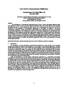
3. Communication Control Middleware 3.1 System Overview As shown in Fig. 1, the communication control middleware on each mobile host can form a cluster network by creating high-speed wireless links between neighboring mobile hosts that agree to cooperative communication, and the network then shares low-speed wireless links. Generally, a cluster network is formed by mobile hosts or devices within a narrow area. In addition to providing communication between cluster networks, the communication control middleware provides a function to recover lost packets, overcome bandwidth shortages, reduce delay, and overcome jitter. Since the state of a network changes dynamically in a mobile computing environment, the communication control middleware regularly monitors the state of each route and controls the packet distribution based on the current state.
3.2 Implementation Layer As there are various types of real-time streaming applications, users should use the application appropriate to their usage. Therefore, we implement the
133
B
Y
A
X
Cluster2
based on information obtained using the traceroute command. Because the PDF system considers neither the bandwidth nor the delay of each route, though, it normally does not work if there are large delay and bandwidth differences between the routes. Although this system is effective for stable wireless networks and wired networks, it is not well suited to unstable mobile computing environments where users move rapidly. The Multitrack method [3] provides high-quality, highly reliable multimedia delivery to mobile hosts. Multitrack forms a cluster network consisting of the mobile hosts of users who want to obtain the same multimedia content. The mobile hosts within the cluster network each receive part of the multimedia data. They then exchange the data within the cluster network to complement what each other user has. Everyone with a mobile host in the cluster network can thereby obtain multimedia content of higher quality than if one mobile host received all the data. However, Multitrack considers only one-way communication from one server in the Internet to several mobile hosts; it does not consider one-way communication from mobile hosts in the cluster network to hosts in the Internet or two-way communication among the mobile hosts, such as video chat. Therefore, Multitrack does not address packet loss and delay. Moreover, Multitrack assumes the packets sent are all the same size. Thus, the packet distribution method needs to be refined.
Cluster1
IJCSNS International Journal of Computer Science and Network Security, VOL.6 No.1B, January 2006
C Z Fig. 1. Communication between cluster networks
communication control middleware between the IP and the transport layers. As there are various communication protocols for real-time streaming (e.g., H.323, SIP, and RTSP), we made it possible for the communication control middleware to communicate regardless of the protocol by intercepting the packets passing between the IP and transport layers. The communication control middleware use iptables and divert sockets [4] to add the control between the IP and transport layers. The packets are returned to the kernel after the control is added. This middleware inserts an extension header that includes the information needed for communication control following the IP header. The communication control middleware refers to information in the extension header when communication is controlled.
3.3 Cluster Formation and Information Exchange For communication, the communication control middleware forms alliances to create a cluster network. A host that is actually communicating will form and manage the alliances within a cluster, and is defined as the alliance leader (AL), while a host that lends the AL communication resources is defined as an alliance member (AM). The AL broadcasts information about itself to the AMs. When an AM receives this information, the AM replies to the AL with information about itself. The AL receives this information and stores it in an alliance list containing information about the hosts in the cluster network. This host information exchange is executed every three seconds, so the list of alliance members is updated at defined intervals in advance. When another cluster network is formed, the communication control middleware exchanges the cluster network information with the AL on the other side. The AL in the first cluster formed is defined as AL1, and the AL in the second cluster formed is defined as AL2. AL1 sends its cluster network information to AL2, and AL2 replies with its cluster information. When AL1 receives the cluster information from AL2, it stores the information in its alliance list. This exchange of cluster information between ALs is executed at defined intervals, and the alliance lists are updated at these intervals.
3.4 Route Measurement The sender measures the bandwidth, the packet loss rate, and the delay of each route by sending a measurement
IJCSNS International Journal of Computer Science and Network Security, VOL.6 No.1B, January 2006
134
0
15 route ID
31
ID
Route
sequence number
1
A→X
X
packet loss rate
2
A→B→X
B
3
A→C→X
C
X
4
A→Y→X
Y
X
5
A→Z→X
Z
X
6
A→B→Y→X
B
Y
X
7
A→B→Z→X
B
Z
X
8
A→C→Y→X
C
Y
X
9
A→C→Z→X
C
Z
X
bandwidth timestamp
Fig. 2. Measurement packet format
packet along each route every second (Fig. 2). The measurement packet is composed of the route ID, sequence number, bandwidth, packet loss rate, and timestamp. The route ID shows the identifier of the route, the sequence number shows the sequence of the packet, and the timestamp shows the transmission time of the packet. The bandwidth and packet loss rate are set to 0 in the sender. Two measurement packets are continuously sent to measure the bandwidth of each route. The receiver calculates the bandwidth based on the difference in the packet arrival times [5]: bandwidth =
packetsize T 2 −T1
(1)
Packet format X
Fig. 3. Packet format for each route
frequently because the communication is carried over multiple routes in a mobile computing environment. A buffering time of 150 ms is added to the communication control middleware to reduce the effects of both the delay differences between routes and the jitter. However, since the delay should be kept below 400 ms in two-way communication [6], the buffering time must not exceed 400 ms.
3.7 FEC where packetsize is the size of the measurement packet, T1 is the time when the first packet arrives, and T2 is the time when the second packet arrives. The receiver stores the calculated bandwidth in the bandwidth field of the measurement packet and sends it back to the sender. The sender determines the round-trip time (RTT) based on the difference between the timestamp of the measurement packet and the time when the packet arrives. It calculates the packet loss rate from the sequence number of the measurement packets. The calculated route information is stored in a route list, which contains the route information.
3.5 Packet Distribution The communication control middleware enables communication over multiple routes by distributing or relaying packets, so it can provide higher aggregate bandwidth. Consider the case where A communicates with X in Fig. 1. When a packet is to be sent to X, A can send it over nine possible routes by source routing, as shown in Fig. 3. The packet that A sends can be relayed to X via B, C, Y, and Z. The packet distribution method affects the end-to-end throughput, so how the packet is distributed to each route is important. Details of the evaluated packet distribution methods are given in Section 4.
3.6 Buffering and Packet Ordering Generally, since buffering and packet ordering is executed by real-time transport protocol (RTP) in the application layer, the buffering time depends on the application. During communication, the packet order changes
Since packets are often lost in a mobile computing environment, the video can be distorted and the sound interrupted during real-time multimedia streaming. Moreover, real-time streaming applications do not have a function to recover lost packets. The communication control middleware recovers lost packets by using FEC (in which the sender sends redundant packets). If the receiver detects packet loss, these are recovered using the redundant packets. If there is a large delay difference between routes or a lot of jitter, FEC can also reduce the delay. The effect of sending packets at a lower rate on multiple independent routes in effect transforms bursty loss into uniform loss, thus increasing the efficiency of FEC techniques. Naturally, given a number of independent routes each with a different loss behavior, source bit rate, and total amount of FEC protection, there should be an optimum partition of sending rates for each route in order to minimize the irrecoverable loss probability (i.e., the probability that FEC cannot recover lost packets in an FEC block). For a Reed-Solomon code RS(N,K) containing K data packets and N − K redundant packets, the irrecoverable loss probability is the probability that more than N − K packets are lost per N packets. The theoretical irrecoverable loss probability P is calculated by K
k −i N − K
P = K ∑i C p (1− p) ∑ 1
i =0
⎧ ⎪ t=⎨ ⎪⎩
0
i
k
i
J =t
C p (1− p) j
N −K
(N − K < i ≤ K )
N − K − i +1
(0 ≤ i ≤ N − K )
j
N −K − j
(2)
IJCSNS International Journal of Computer Science and Network Security, VOL.6 No.1B, January 2006
135
Qij Table 1: Theoretical irrecoverable loss probability (%) RS(N,K) (15,13) (15,12) (15,11) (15,10)
2 0.06206 0.00456 0.00023 0.00001
Loss probability without FEC (%) 4 6 8 10 0.42374 1.22214 2.47971 4.15371 0.06175 0.26462 0.7077 1.46178 0.00673 0.04047 0.14456 0.37343 0.00046 0.00454 0.02182 0.071
where p is the loss probability of the route. Table 1 shows the theoretical irrecoverable loss probability. In a mobile computing environment, the FEC redundancy should change dynamically to keep the loss probability under 0.1%. If this is done, the loss probability will not affect the quality of real-time streaming between hosts. For example, RS(15,13) is set when the loss probability without FEC is under 2%. RS(15,12) is set when the loss probability without FEC is from 2% to 4%. RS(15,11) is set when the loss probability without FEC is from 4% to 6%. RS(15,10) is set when the loss probability without FEC is over 6%.
upqi
upqi
4.1 Asymmetrical Bandwidth We developed a prototype for testing cluster network formation, cluster network information exchange, route measurement, multiple route communication, buffering, and packet ordering. For the multiple route communication, we implemented three packet distribution methods. Generally, the uplink and downlink bandwidths are asymmetrical in a wireless network. Therefore, all three packet distribution methods consider both the uplink and downlink bandwidths.
downqj
before send: (t0 - t1) x upbwi upqi
(t0 - t1) x downbwj downqj
after send : sendsize
sendsize
Fig. 4. Virtual queue (VQ)
volume of data stored in the downlink queue of host j. Qij is the total of upqi and downqj, and the sender distributes the packet to the route with the smallest Qij:
Q = upq + downq ij
4. Packet Distribution Methods
downqj
i
(3) j
Before and after a packet is sent, upqi and downqj are updated. The uplink bandwidth of host i and the downlink bandwidth of host j are upbwi and downbwj; t1 is the time when the next packet is sent; t0 is the time when the previous packet was sent; and (t0 - t1) * upbwi and (t0 - t1) * downbwi are the data volume reductions in the VQ when the previous packet was sent and before the next packet is sent. When the route (the one with the smallest Qij) is decided, (t0-t1) * upbwi and (t0-t1) * downbwi are respectively subtracted from upqi and downqj, and the packet is distributed to the route. After the packet is sent, Qij is updated by adding the size of the sent packet.
4.4 Queuing-delay-based Distribution (Method 3) 4.2 Bandwidth-based Distribution (Method 1) First, the sender selects a host within its own cluster network, based on the ratio of each uplink bandwidth, to relay a packet. Next, the sender selects a host within the other cluster network, based on the downlink bandwidth ratio, to relay the packet. Once the sender decides which hosts will relay the packet, the packet is distributed accordingly. The bandwidth of each route is updated dynamically at defined intervals, so this packet distribution method disperses the packets based on the uplink and downlink bandwidths.
4.3 Virtual-queue-based Distribution (Method 2) The sender has a virtual queue (VQ) for each route (Fig. 4). A VQ is expressed as a combination of an uplink queue and a downlink queue. Qij is the volume of data stored in the virtual queue; upqi and downqj are, respectively, the volume of data stored in the uplink queue of host i and the
Method 3 uses transmission delayij and the time at which sending of the data stored in the VQ has finished. The sender estimates the time when the packet will arrive at the receiver and distributes the packet to the route for which the arrival time is the earliest. Dij is the arrival time for each route, and upqi/upbwi and downqj/downbwj are, respectively, the times at which the sending of the packets in the uplink queue and downlink queue is finished. The sender distributes the packets to the route with the smallest Dij:
D
ij
=
upq downq + upbw downbw
(4)
j
i
i
j
As in method 2, upqi and downqj are updated before and after packet transmission.
IJCSNS International Journal of Computer Science and Network Security, VOL.6 No.1B, January 2006
Route 1 Route 2 Route 3 Route 4
Source routing information AL1 -> AL2 AL1 -> AM2 -> AL2 AL1 -> AM1 -> AL2 AL1 -> AM1 -> AM2 -> AL2
AL1
AL2
Router A
Router B
AM1
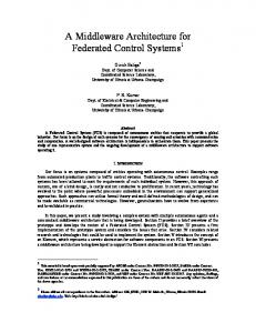
5. Evaluation 5.1 Experimental Environment We constructed a virtual network with the NIST Net emulator [7], assuming asymmetric bandwidth in a mobile computing environment, and tested the three packet distribution methods described in Section IV. Figure 5 illustrates the experimental environment and Table 3 gives the details of the four routes between AL1 and AL2. The communication control middleware was executed in each mobile node, AL1 was the sender and AL2 was the receiver node, and AM1 and AM2 were relay nodes. Although these nodes were distinguished in the prototype, the communication control middleware will automatically identify these nodes in the future. We directly connected AL1 and AM1 with a cable as cluster network1 and similarly connected AL2 and AM2 as cluster network2 to evaluate the performance of the alternative packet distribution methods. (Note, though, that the communication between an AL and an AM would occur through a high-speed wireless link in an actual environment.) As the bandwidth was broad enough and the delay was small enough, these nodes were connected by a short cross cable. Communication between cluster network1 and cluster network2 was done using the low-speed wireless links. Routers A and B emulated a bandwidth and a delay close to those of a low-speed wireless link. Router A controlled the uplink bandwidth and delay of AL1 and AM1 through the NIST Net emulator. Router B controlled the downlink bandwidth of AL2 and AM2 by NIST Net. Since the prototype did not have a function to dynamically change the FEC redundancy through the communication, the packet loss rate was set to zero or within a uniform distribution (0-10 ms). The queue lengths in the routers were set to 50. A USB-compatible camera was connected to AL2 and to AL1; they communicated in real time using Gnome-Meeting, a TV conferencing system for Linux. Although the bandwidth and delay change dynamically in an actual environment, for simplicity we kept them constant for a theoretical bit rate. Moreover, because the accuracy of bandwidth measurement using measurement packets was low in the prototype, the uplink and downlink bandwidths were kept at the theoretical constant bit rate of each mobile host.
C luster2
Table. 2: Route list at AL1
C luster1
136
AM2 Fig. 5. Experimental environment
5.2 Experiment 1 The bandwidth, delay, and loss probability of the four routes between AL1 and AL2 in experiment 1 are shown in Table 3. The uplinks of routes 1 and 2 were shared, as were those of 3 and 4. Likewise, the downlinks of routes 1 and 3 and routes 2 and 4 were shared. In this experiment, we evaluated the performance of the three packet distribution methods in an asymmetric bandwidth environment. As the downlink of FOMA F2402 communications (NTT DoCoMo’s 3G cellular phone) is 384 kbps, with a symmetric uplink, we set the downlink bandwidth of all hosts to 384 kbps and the uplink bandwidth of all hosts to 128 kbps (one-third of the downlink bandwidth). The delay and the loss probability were the same for all routes so that we could evaluate the basic characteristics of each packet distribution method. The delay was generated from a uniform distribution ranging from 0 ms to the set up value. The loss probability was set to 0%. The video, which had a maximum bit rate of 100 to 700 kbps, was streaming to AL2 from AL1 at 100 kbps. In this streaming, AL1 communicated with AL2 using packet distribution method 1, 2, or 3, and we measured the irrecoverable loss probability at the receiver. Figure 6 shows the irrecoverable loss probability at AL2. The probability increased when the bit rate reached about 400 kbps. The streaming at 400 kbps was congested, and packets were lost because the uplink and downlink bandwidths of AL1 and AL2 were both 384 kbps. On the other hand, even where the bit rate hit 500 kbps with the communication using packet distribution method 3, communication continued without packet loss. Even though the bit rate was 550 kbps, the irrecoverable loss probability was under 0.1%. In the experimental environment, all routes could be effectively used in the communication with packet distribution method 3, so logically the uplink and downlink bandwidths could both be increased to 576 kbps. When the uplink and downlink bandwidths were symmetrical for each route, and there was no delay difference between the routes, communication was achieved with a lower irrecoverable loss probability when using packet distribution method 3.
IJCSNS International Journal of Computer Science and Network Security, VOL.6 No.1B, January 2006
Table 3: Set-up parameters of each route in experiment 1
Table 4: Set-up parameters of each route in experiment 2
Route 1 192 384 100
Route 2 192 192 100
Route 3 384 384 100
Route 4 384 192 100
0
0
0
0
Irrecoverable loss probability (%)
1 Method 1 Method 2
0.8
Method 3
0.6 0.4 0.2 0 400
Uplink (kbps) Downlink (kbps) Delay (ms) Loss probability (%)
Irrecoverable loss probability (%)
Uplink (kbps) Downlink (kbps) Delay (ms) Loss probability (%)
137
12
8
Route 3 384 384 100
Route 4 384 384 100
0 - 10
0 - 10
0 - 10
0 - 10
6 4 2 0 0
Fig. 6. Comparison of packet distribution methods
50
100 Elapsed time (sec)
150
Fig. 7. Irrecoverable loss probability with FEC Increasing rate of redundant traffic (%)
Table 4 shows the bandwidth and the delay for each route in experiment 2. The uplink and downlink bandwidths and the delay were the same in all routes, and the loss probability in each route was increased from 0 to 10% in steps of 2% at 3-s intervals. The video, which had a maximum bit rate of 400 kbps, was streamed to AL2 from AL1. In this streaming, AL1 communicated with AL2 using packet distribution method 3, which worked well in experiment 1. We evaluated the effect of FEC with Reed-Solomon code RS(15,13), RS(15,12), RS(15,11), RS(15,10), and not using FEC. Moreover, we developed a method for updating the FEC redundancy based on the measured loss probability as described in Section 3.7. Figure 7 shows the irrecoverable loss probability for each FEC application. The irrecoverable loss probability without FEC increased when the elapsed time reached 20 s. The results were generally close to what we expected. Higher redundancy lowered the irrecoverable loss probability. Our developed dynamic updating redundancy method worked well. As shown in Fig. 8, the increasing rate of redundant traffic rose when the redundancy increased. However, the dynamic method did not exceed the increasing rate of redundant traffic for RS(15,11) and RS(15,10). Thus, an adequate level of redundancy should be selected based on the measured loss probability as in the proposed method.
Route 2 384 384 100
No-FEC RS(15,13) RS(15,12) RS(15,11) RS(15,10) Dynamic
10
450 500 550 Bit rate set up on video streaming (kbps)
5.3 Experiment 2
Route 1 384 384 100
1.6
1.4
1.2
1 (15,13)
(15,12)
(15,11)
(15,10)
dynamic
RS(N,K) of applied FEC method
Fig. 8. Increasing rate of redundant traffic
5.4 Experiment 3 Table 5 shows the bandwidth and delay for each route in experiment 3. Both the uplink and downlink bandwidths in all routes were the same, and the loss probability in each route was set to 0. Only the delay differed between routes. Routes 1 and 2 had a 100-ms delay, while routes 3 and 4 had a 400-ms delay. The video, which had a maximum bit rate of 400 kbps, was streamed to AL2 from AL1. Generally, since buffering and packet ordering are executed by RTP in the application layer, the length of the buffering time depends on the application. The packet order changed frequently since the communication occurred over multiple routes in a mobile computing environment. In this experiment, we evaluated the effect of buffering time under packet distribution method 3.
IJCSNS International Journal of Computer Science and Network Security, VOL.6 No.1B, January 2006
Table 5: Set-up parameters of each route in experiment 3
0
0.1 0.08 0.06 0.04 0.02 0 150
200 300 Buffering time (ms)
400
Fig. 9. Irrecoverable loss probability with buffering
Route 4 384 384 0 - 400
0
0
0
0
5 4 3 2 1 0 400+F EC
0
Route 3 384 384 0 - 400
400
0
Route 2 384 384 100
300+F EC
0
Uplink (kbps) Downlink (kbps) Delay (ms) Loss probability (%)
Route 1 384 384 100
300
Route 4 384 384 400
200+F EC
Route 3 384 384 400
200
Route 2 384 384 100
150
Route 1 384 384 100
Irreco verab le lo ss p ro bab ility (% )
Irrecoverable loss probability (%)
Uplink (kbps) Downlink (kbps) Delay (ms) Loss probability (%)
Table 6: Set-up parameters of each route in experiment 4
150+F EC
138
Buffering time (ms)
As shown in Fig. 9, the irrecoverable loss probability decreased when the buffering time was increased. When the buffering time was over 300 ms, the irrecoverable loss probability was 0. Although there were some irrecoverable losses in the communication when the buffering time was 150 or 200 ms, the quality of communication was not affected because the loss probability remained very low at under 0.1%. Therefore, the buffering time of 150 ms used in the proposed communication middleware was sufficient.
5.5 Experiment 4 In experiment 4, the uplink and downlink bandwidths were the same for each route and the loss probability was equal to zero (Table 6). NIST Net generated the delay-jitter of routes 3 and 4 from a uniform distribution ranging from 0 to 400 ms. The video, which had a maximum bit rate of 400 kbps, was streamed to AL2 from AL1. In this streaming, AL1 communicated with AL2 using packet distribution method 3. We evaluated the effect of dynamic FEC and buffering in this experiment. Figure 10 shows the irrecoverable loss probability with buffering or with buffering and FEC. The irrecoverable loss probabilities without FEC were higher than those with the dynamic FEC method. Moreover, the irrecoverable loss probabilities with buffering and FEC did not significantly differ when the buffering time ranged from 150 to 300 ms. Therefore, when the buffering and FEC are applied to the communication control middleware, a buffering time of 150 ms is sufficient. However, since the delay should be kept below 400 ms in two-way communication, the buffering time must not exceed 400 ms.
Fig. 10. Irrecoverable loss probability with FEC and buffering
6. Conclusion We have described communication control middleware for real-time streaming between link-aggregated mobile networks. This middleware connects two link-aggregated mobile networks by creating high-speed wireless links between the hosts in one mobile network and the hosts in another. The low-speed wireless links of the hosts can then be shared, enabling high-speed data communication through the Internet. This middleware controls the traffic sent over multiple routes and takes into account the uplink and downlink bandwidths and the delay differences for each possible route. Testing using a prototype showed that when packets are distributed based on their estimated arrival time by using a virtual queue and the queuing delay, stable streaming communication can be achieved without packet loss. Moreover, we determined the effect of applying 150-ms buffering and the dynamic FEC method. In our future work, we plan to further evaluate the buffering and FEC function and will consider an environment in which the network state changes dynamically. We will also evaluate our middleware when it is used in actual mobile real-time streaming communication.
IJCSNS International Journal of Computer Science and Network Security, VOL.6 No.1B, January 2006
Kiyoko Tanaka
References [1] J. Apostolopoulos and M. Trott, “Path Diversity for Enhanced Media Streaming,’’ IEEE Communications Magazine, pp.80-87, 2004. [2] T. Nguyen and A. Zakhor, “Path Diversity with a Forward Error Correction (PDF) System for Packet Switched Networks,’’ IEEE INFOCOM, pp.663-672, 2003. [3] Y. Saito, S. Ishihara, H. Mineno, T. Mizuno, and T. Watanabe, “Evaluation of Traffic Dispersion Methods for Synchronous Distributed Multimedia Data Transmission on Multiple Links for Groups of Mobile Hosts,’’ Journal of Applied Systems Studies Methodologies and Applications for Systems Approaches, Vol.5, No.2, pp.169-178, 2004. [4] Divert Sockets for Linux: http://sourceforge.net/projects/opdivert [5] K. Lai and M. Baker, “Nettimer: A Tool for Measuring Bottleneck Link Bandwidth’’ USENIX Symposium on Internet Technologies and Systems, pp.123-134, 2001. [6] ITU-T Rec. G.114, “One-Way Transmission Time,’’ 2002. [7] NIST Net: http://www-x.antd.nist.gov/nistnet/
received his B.E. Hiroshi Mineno and M.E. degrees from Shizuoka University, Japan in 1997 and 1999, respectively. From 1999 to 2002, he was a researcher in the NTT Service Integration Laboratories. In 2002, he joined the Department of Computer Science of Shizuoka University as a research assistant. His research interests include mobile computing and ubiquitous computing. He is a member of the IEEE, the ACM, the IEICE, and the IPSJ (Information Society of Japan).
Koji Suzuki
received his B.I. degree from Shizuoka University, Japan in 2003. He is a graduate school student of Informatics, Shizuoka University. His research interests include mobile multimedia communication and mobile computing. He is a member of the IPSJ.
139
received her B.E. and M.E. degrees in science for open and environmental systems from Keio University, Japan in 2000 and 2002, respectively. She joined NTT DoCoMo Inc. in 2002. She is currently engaged in R&D concerning mobile Internet technology.
Hideharu Suzuki
received his B.E. and M.E. degrees in engineering from Chiba University, Japan in 1989 and 1991, respectively. From 1991 to 1999, he was with NTT. In 1999, he joined NTT DoCoMo Inc. He is currently a manager and is engaged in R&D concerning mobile Internet technology. He is a member of the IEICE.
Norihiro Ishikawa received his B.E., M.E., and Ph.D. degrees in information engineering from Kyoto University, Japan in 1978, 1980, and 2003, respectively. From 1980 to 1999, he was with NTT. In 1999, he joined NTT DoCoMo Inc. He is currently a director and is engaged in R&D concerning mobile Internet technology and in international standardization activities. He is a member of the IEICE and the IPSJ. Tadanori Mizuno received his B.E. degree in industrial engineering from the Nagoya Institute of Technology in 1968 and his Ph.D. in computer science from Kyushu University, Japan, in 1987. In 1968, he joined Mitsubishi Electric Corp. In 1993, he became a Professor in the Faculty of Engineering, Shizuoka University, Japan. He moved to the Faculty of Information, Shizuoka University in 1995. His research interests include mobile computing, distributed computing, computer networks, broadcast communication and computing, and protocol engineering. He is a member of the IPSJ, the IEICE, the IEEE Computer Society, and the ACM.
IJCNS International Journal of Computer Science and Network Security, Vol. 5 No.8 August 2005
Manuscript received August 2005. Manuscript revised August 22, 2005.