1666â1693. 5. Eric W. Weisstein, âTorus,â from MathWorld-A Wolfram Web. Resource, http://mathworld.wolfram.com/Torus.html. 6. The ray-trace program used ...
Compact system description for systems comprising a tilted plane parallel plate Jack van den Eerenbeemd and Sjoerd Stallinga
A paraxial model describing the astigmatism generated by a plane-parallel plate is derived. This model fits the framework of the 4 ⫻ 4 matrix formalism that Arsenault used to describe cylindrical lenses. The framework including this new model is used to build a compact system description of a plane-parallel plate combined with a cylindrical lens, from which several imaging properties are derived. Calculation results are compared with ray-trace simulation results and measurements. Both the ray-trace and the experimental results are in excellent agreement with the calculated results. © 2007 Optical Society of America OCIS codes: 080.2730, 220.4830, 210.4770.
1. Introduction
It is well known that like cylindrical lenses, a planeparallel plate (PPP) in a diverging or converging beam generates astigmatism.1 For cylindrical lenses Arsenault2,3 proposed a 4 ⫻ 4 matrix formalism to describe the imaging properties of these lenses. In this paper we expand this matrix formalism with a paraxial model for the PPP. The formalism can now be used to describe systems comprising both PPPs and cylindrical lenses. To illustrate the usefulness of this we examine a servo branch of a DVD optical recording light path. In optical recording devices the astigmatic focusing method is often used for controlling the distance between the lens and the disk.4 The required astigmatism is often generated by a cylindrical lens or by a PPP in a converging beam. Normally the same detector used for generating the focus error is also used for generating a tracking signal by means of push–pull detection.4 This means that ideally one of the focal lines of the astigmatic beam has to be oriented at 45° with respect to the push–pull lobes on the detector. A cylindrical lens can always be rotated such that the astigmatism it generates fulfills the above-
The authors are with Philips Research Laboratories, High Tech Campus 34, 5656 AE, Eindhoven, the Netherlands. J. van den Eerenbeemd’s e-mail address is jack.van.den.eerenbeemd@ philips.com. Received 21 August 2006; accepted 8 September 2006; posted 20 September 2006 (Doc. ID 74179); published 4 January 2007. 0003-6935/07/030319-08$15.00/0 © 2007 Optical Society of America
mentioned requirement. A PPP, however, is usually also used as a beam splitter. This means that the orientation of the astigmatism generated by a beamsplitting PPP depends on how the light path is oriented with respect to the tracks on an optical disk. For space reasons the light path might be oriented such that the astigmatism generated by a beamsplitting PPP is parallel to the push–pull lobes. This would require a sophisticated detector layout to generate both the focus-error and the tracking-error signals. Instead of a complicated detector a beamsplitting cube combined with a cylindrical lens can be used since a cube does not generate astigmatism in a converging beam. A beam-splitting cube, however, is bulkier compared with a beam-splitting PPP and generates spherical aberration in the light path toward the disk. Here we present a novel solution where the astigmatism generated by the PPP is combined with that of a cylindrical lens such that the desired orientation and amount of astigmatism arises on the detector. A large number of parameters are involved in the design of such a system. This makes the use of a ray-tracing program to design the system rather awkward. We present in Section 2 a paraxial model for describing nonrotationally symmetric optical components that includes the description of the astigmatism generated by a PPP based on the 4 ⫻ 4 matrix formalism. Section 3 is used to present an example for which a system matrix is derived whose various general properties are discussed. In Section 4 the calculated results are compared to the numerical results obtained by ray tracing. The calculated results are then compared with measurements. 20 January 2007 兾 Vol. 46, No. 3 兾 APPLIED OPTICS
319
2. Theory
In this section first a general optical power matrix is derived that is used to describe toroidal, spherical, and cylindrical surfaces. Next the translation matrix is derived from which a representation of a PPP is obtained. A.
Derivation of the 4 ⫻ 4 Power Matrix
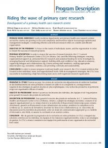
We start by considering the refraction of a narrow pencil of light concentrated around the chief ray that propagates in the direction k, with |k| ⫽ 1, by a surface (see Fig. 1). In a medium with refractive index n we then have nk ⫽ 关x, y, 共n2 ⫺ 2兲1兾2兴,
(1)
Fig. 1. Refraction of the chief ray and an arbitrary ray by a surface drawn in the meridional plane. The difference between the propagation vectors of both rays equals ␦k.
where ⫽ 共x2 ⫹ y2兲1兾2 is the absolute value of the projection of the propagation vector nk onto the XY plane. For an arbitrary ray inside the pencil the propagation direction is then given by k ⫹ ␦k, with |k ⫹ ␦k| ⫽ 1 and |␦k|⬍⬍ 1. From this we obtain
␦y ⫺ 冑n2 ⫺ 2ay ⫽ ␦y⬘ ⫺ 冑n⬘2 ⫺ 2ay.
n共k ⫹ ␦k兲 ⫽ 共x ⫹ ␦x, y ⫹ ␦y, 共n2 ⫺ 共 ⫹ ␦兲2兲兲1兾2, (2)
And because at a single surface the position of a ray does not change r ⫽ r⬘, so we can write
so,
冉
n␦k ⫽ ␦x, ␦y,
⫺ · ␦
冑n2 ⫺ 2
冊
.
(3)
Refraction occurs at a curved surface given by z ⫽ f共x, y兲. For paraxial rays, f is approximated by expanding it in x and y to the second order: z⬇
1 2
␦⬘ ⫽ ␦ ⫺ 共冑n⬘2 ⫺ 2 ⫺ 冑n2 ⫺ 2兲 pxx pxy ⫻ r ⬅ ␦ ⫹ Pr, pyx pyy
冋
⫺ax ⫽
⭸z ⫽ pxx x ⫹ pxyy, ⭸x
⭸z ⫺ay ⫽ ⫽ pyx x ⫹ pyyy. ⭸y
冋 册 冋 册冋 册 关 兴冋 册 r⬘ 1 ⫽ ␦⬘ P
Here pxy was set equal to pyx, which is valid because they act on the surface in the same indiscernible way. However, to keep the symmetry in the notation, they will both be used separately. Since |ax|,|ay|⬍⬍ 1, a ⬇ 共ax, ay, 1兲. We can now formulate Snell’s law as n共k ⫹ ␦k兲 ⫻ a ⫽ n⬘共k⬘ ⫹ ␦k⬘兲 ⫻ a.
(6)
After expanding the cross product it is found that in the zeroth order x ⫽ x⬘ and y ⫽ y⬘ or ⫽ ⬘. These are the chief ray invariants. In the first order we have APPLIED OPTICS 兾 Vol. 46, No. 3 兾 20 January 2007
(8)
0 r r ⫽ L , 1 ␦ ␦
(9)
where 1 is the 2 ⫻ 2 unit matrix, and 0 is a 2 ⫻ 2 null matrix. To determine the power matrix of some simple surfaces we start by considering a part of the surface of a torus. The surface sag of a torus that is azimuthally symmetric about an axis in the XZ plane and parallel to the y axis with an inner radius R and a tube radius r is given by5 z ⫽ ⫾共R ⫾ r兲 ⫾
(5)
册
(7)
where P is the optical power matrix. Using partitioned matrices this reads
1 兺ij pijrirj ⫽ 2