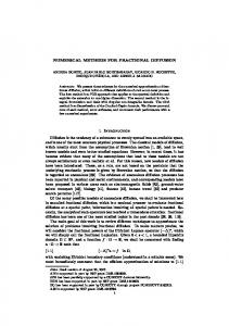
Jan 4, 2017 - 1 y/c x/c. Figure . (Color online) The geometric shape of NACA (solid ... As analysis objects, we adopt NACA0012, NACA0006, and Ishii ...
International Journal of Computational Fluid Dynamics
ISSN: 1061-8562 (Print) 1029-0257 (Online) Journal homepage: http://www.tandfonline.com/loi/gcfd20
Comparative studies of numerical methods for evaluating aerodynamic characteristics of twodimensional airfoil at low Reynolds numbers D. Lee, T. Nonomura, A. Oyama & K. Fujii To cite this article: D. Lee, T. Nonomura, A. Oyama & K. Fujii (2017) Comparative studies of numerical methods for evaluating aerodynamic characteristics of two-dimensional airfoil at low Reynolds numbers, International Journal of Computational Fluid Dynamics, 31:1, 57-67, DOI: 10.1080/10618562.2016.1274398 To link to this article: http://dx.doi.org/10.1080/10618562.2016.1274398
Published online: 04 Jan 2017.
Submit your article to this journal
Article views: 49
View related articles
View Crossmark data
Full Terms & Conditions of access and use can be found at http://www.tandfonline.com/action/journalInformation?journalCode=gcfd20 Download by: [106.181.200.201]
Date: 18 February 2017, At: 02:34
INTERNATIONAL JOURNAL OF COMPUTATIONAL FLUID DYNAMICS, VOL. , NO. , – http://dx.doi.org/./..
Comparative studies of numerical methods for evaluating aerodynamic characteristics of two-dimensional airfoil at low Reynolds numbers D. Leea , T. Nonomurab , A. Oyamab and K. Fujiic a Department of Aeronautics and Astronautics, University of Tokyo, Sagamihara, Japan; b Department of Space Transportation Engineering, Institute of Space and Astronautical Science/JAXA, Sagamihara, Japan; c Department of Information Science, Tokyo University of Science, Tokyo, Japan
ABSTRACT
ARTICLE HISTORY
This study investigates the predictability of the aerodynamic performance of some numerical methods at low Reynolds numbers and their dependency on the geometric shape of airfoil. We conducted three-dimensional large-eddy simulations (3-D LES), two-dimensional laminar simulations (2-D Lam), and Reynolds-averaged Navier–Stokes simulations with Baldwin–Lomax (2-D RANS(BL)) and Spalart– Allmaras (2-D RANS(SA)) turbulence models. Although there is little discrepancy between the 3-D LES, 2-D Lam, and 2-D RANS(SA) results in terms of the lift and drag characteristics, significant differences are observed in the predictability of the separation and reattachment points. The predicted lift, separation, and reattachment points of the 2-D Lam are qualitatively similar to those of the 3-D LES, except for high angles of attack at which a massive separation occurs. The 2-D RANS(SA) shows good predictability of the lift and separation points, but it does not estimate reattachment points accurately. The 2-D RANS(BL) fails to predict the precise separation points, which results in a poor lift predictability. These characteristics appear regardless of the airfoil geometry shapes. The results suggest that a 2-D Lam without any turbulence models can be used to estimate qualitative airfoil aerodynamic characteristics at the low Reynolds numbers.
Received July Accepted December
1. Introduction In recent years, the demand for micro air vehicles (MAV) and unmanned aerial vehicles (UAV) has increased. These aircraft are usually small and have a low cruising speed; thus, a chord-length-based flight Reynolds number falls into the low Reynolds number region (Rec = 104 –105 ). The airfoil aerodynamic characteristics in this region are sensitive to several factors, for example, airfoil geometry shape (e.g., leading edge shape, maximum thickness, and camber strength) (Laitone 1996; Abdo and Mateescu 2005), free stream turbulence intensity (Wang et al. 2014; Stevenson et al. 2014; Hosseinverdi and Fasel 2015), Reynolds numbers (Yarusevych, Sullivan, and Kawall 2009; Kondo et al. 2013; Olson et al. 2013), and formation of a laminar separation bubble (LSB) (Lissaman 1983; Lin and Pauley 1996; Shan, Jiang, and Liu 2005). It is well known that the aerodynamic characteristics at low Reynolds numbers are significantly different from those at high Reynolds numbers (Carmichael 1982; Mueller and DeLaurier 2003), and, hence, some general knowledge of aerodynamic characteristics of high Reynolds number conditions cannot be directly applied at low Reynolds numbers. Thus, it is necessary to CONTACT D. Lee
lee@flab.isas.jaxa.jp
© Informa UK Limited, trading as Taylor & Francis Group
KEYWORDS
Low Reynolds number; aerodynamic characteristics; airfoil shape; numerical methods; laminar separation bubble; separation; reattachment
understand the aerodynamic characteristics at low Reynolds numbers. Many experimental and numerical methods have been proposed to evaluate airfoil aerodynamic characteristics. To evaluate these characteristics via a numerical simulation, the accuracy of the numerical methods should be verified with respect to the predictability of the aerodynamic characteristics. Although highly accurate numerical methods (e.g., direct numerical simulation or largeeddy simulation) have been proposed, these simulations still require very large computational resources. Consequently, a two-dimensional (2-D) simulation is more desirable than a three-dimensional (3-D) simulation from an engineering point of view. Some approaches with turbulence or transition models have been conducted to calculate low Reynolds number flows (Windte, Scholz, and Radespiel 2006; Rumsey and Spalart 2009; Catalano and Tognaccini 2010; Counsil and Goni Boulama 2012; Crivellini and D’Alessandro 2014). On the other hand, the results reported by Kojima et al. (2013), Kondo et al. (2014), and Lee et al. (2015) show that a 2-D laminar simulation without adopting any turbulence model, which has a relatively low computational cost, can be adopted
58
D. LEE ET AL.
to estimate qualitative aerodynamic characteristics and the formation of an LSB in a wide range of low Reynolds number conditions, except for high angles of attack at which a massive separation occurs from the leading edge. As already noted, however, the airfoil aerodynamic characteristics at low Reynolds numbers are very sensitive to the airfoil shape. Thus, it is necessary to clarify the relationship between the airfoil geometry shape and the predictability of the numerical methods. In this study, we carry out three-dimensional largeeddy simulations (3-D LES), two-dimensional laminar (2-D Lam) simulations, and two-dimensional Reynoldsaveraged Navier–Stokes simulations with Baldwin– Lomax (2-D RANS(BL)) and Spalart–Allmaras (2-D RANS (SA)) turbulence models using three different airfoil shapes. The predictability of the flow-fields and airfoil aerodynamic characteristics for each numerical method at low Reynolds numbers are discussed.
where δ ij is the Kronecker delta and k is the thermal conductivity. The dynamic viscosity coefficient μ is obtained by Sutherland’s law. According to Stokes’ hypothesis, the second viscosity coefficient λ is assumed to be λ = −2μ/3. The rate of strain tensor sij is written as 1 si j = 2
�
∂u j ∂ui + ∂x j ∂xi
� .
(6)
In this study, all variables are normalised by the chord length c, density, dynamic viscosity coefficient, speed of sound, and velocity of the free stream. Thus, the normalised Reynolds number Rec , Mach number M� , and Prandtl number Pr are defined as Rec =
μ∞ c p ρ∞ u∞ c u∞ , , M∞ = , Pr = μ∞ a∞ k
(7)
where cp is the specific heat capacity at constant pressure.
2. Computational setup 2.2. Numerical schemes
2.1. Governing equations The conservative and non-dimensional forms of the compressible Navier–Stokes equations are written as ∂ ∂ρ + (ρu j ) = 0, (1) ∂t ∂x j ∂ ∂p 1 ∂ ∂ (ρui ) + (ρui u j ) = − + τi j , (2) ∂t ∂x j ∂xi Rec ∂x j ∂e ∂ 1 ∂ 1 ∂q j + [(e + p)u j ] = (τi j ui ) − , ∂t ∂x j Rec ∂x j Rec ∂x j (3) where t, ρ, p, and e denote the time, density, static pressure, and total energy per unit volume, respectively. The velocity components in each direction xi ( � x, y, z) are denoted as ui ( � u, v, w) for i = 1, 2, 3. The equations are computed in the generalised curvilinear coordinates (ξ , η, ζ ). The static pressure p and speed of sound a are calculated by � � p 1 p = ρRT = (γ − 1) e − ρuk uk , a2 = γ RT = γ , 2 ρ (4) where γ , R, and T represent the specific heat ratio, gas constant, and temperature, respectively. The viscous stress tensor τ ij and heat flux vector qj are expressed as τi j = 2μsi j + λδi j skk , q j = −k
∂T 1 μ ∂a2 =− , ∂x j γ − 1 Pr ∂x j (5)
... Three-dimensional large-eddy simulation (-D LES) The spatial derivatives of the convective and viscous terms are calculated by the sixth-order compact difference scheme (Lele 1992) and the tenth-order low-pass filtering with filtering coefficient α f = 0.495 (Lele 1992; Gaitonde and Visbal 2000). We do not adopt a subgrid scale model, and hence an implicit large-eddy simulation is performed. For a time integration method, we adopted the second-order backward differencing with the alternate directional implicit symmetric Gauss–Seidel (ADI-SGS) scheme (Fujii 1998) and five sub-iterations (Chakravarthy 1984). Since the present simulations give unsteady solutions, it is thought that they are relatively easy to converge to a solution of each time step. Thus, no preconditioned methods for accelerating the iteration were employed in this study. The three-dimensional large eddy simulation is called as ‘3-D LES’ in the present study. ... Two-dimensional laminar simulation (-D Lam) The convective terms are calculated by the third-order monotone upstream scheme for the conservation law (MUSCL) without limiter (van Leer 1979), and the simple high-resolution upwind scheme (SHUS) proposed by Shima and Jounouchi (1997). The viscous terms are evaluated by the second-order central difference scheme. The second-order backward differencing with the ADISGS scheme (Fujii 1998) is adopted for the time integration. The flow-fields are assumed to be laminar over the entire region, and hence no turbulence models are
INTERNATIONAL JOURNAL OF COMPUTATIONAL FLUID DYNAMICS
employed. Note that this method gives an unsteady solution. The two-dimensional laminar simulation is called as ‘2-D Lam’ in the present study. ... Two-dimensional RANS simulation (-D RANS(BL) and -D RANS(SA)) The methods for evaluating the convective, viscous terms, and time-integration are exactly the same as those of the 2-D Lam simulation. Baldwin–Lomax (Baldwin and Lomax 1978) and Spalart–Allmaras turbulence models (Spalart and Allmaras 1992) are adopted for turbulence analysis without setting of a transition point. The 2-D RANS simulations of each turbulence model are called as ‘2-D RANS(BL)’ and ‘2-D RANS(SA)’ in this study. The entire field is assumed to be a fully turbulent flow in both simulations. In SA turbulence model, the turbulence quantity ν˜ is computed by the following equation:
59
while those in the modified version are given by fv2 =
1 (1 + χ fv1 )(1 − fv2 ) . (12) , fv3 = 3 (1 + χ/5) χ
We apply the modified version and the far-field turbulence quantity is set to be ν˜∞ /ν∞ = 5.0. 2.3. Computational grids and flow conditions As analysis objects, we adopt NACA0012, NACA0006, and Ishii airfoils which are representative of thicksymmetric, thin-symmetric, and thin-cambered airfoils, respectively (see Figure 1). Anyoji et al. (2014) have
� �� � Cb1 ν 2 ∂ ν˜ ∂ ν˜ = Cb1 (1 − ft2 )S˜ν˜ − Cw1 fw − 2 ft2 + uj ∂t ∂x j κ d � � � � 1 ∂ ∂ν ∂ν ∂ ν˜ + (ν + ν˜ ) + Cb2 . (8) σ ∂x j ∂x j ∂xi ∂xi
Detailed descriptions of each term are given by Spalart and Allmaras (1992). The relationship between the turbulence quantity ν˜ and turbulent eddy viscosity μt is μt = ρ ν˜ fv1 , fv1 =
χ3 , 3 χ 3 + Cv1
(9)
where χ = ν/ν. ˜ We note that there are several versions of the SA turbulence model. Rumsey et al. (2001) described two versions of SA turbulence model which are referred to as the standard and modified version in this study. The difference between the two versions is the definition of S˜ which appears in the production term of Equation (8). S˜ is calculated by the following equation: S˜ = fv3 � +
ν˜
fv2 . κ 2d2
(10)
fv2 and fv3 in the standard version are obtained by fv2 = 1 −
χ , fv3 = 1, 1 + χ fv1
(11)
0.1
y/c
0.05 0 -0.05 -0.1 0
0.2
0.4
x/c
0.6
0.8
1
Figure . (Color online) The geometric shape of NACA (solid line, blue), NACA (dashed line, green), and Ishii (dasheddotted line, red) airfoils.
Figure . Computational grids of (a) NACA (thick-symmetric), (b) NACA (thin-symmetric), and (c) Ishii (thin-cambered) airfoils.
60
D. LEE ET AL.
Table . The number of grid points, the maximum grid spacing and time step size of three grids (Rec = . × , α = .°). Grid
Nξ
Nη
Nζ
Total points
�ξ +
�η+
�ζ +
�t+
Grid A Grid B Grid C
,, ,, ,,
. . .
. . .
. . .
. . .
Table . The maximum grid spacing and time step size of each airfoil grid (Rec = . × , α = .°).
reported that the Ishii airfoil shows good aerodynamic performances at low Reynolds numbers. The computational grids around each airfoil are shown in Figure 2. A structured C-type grid is employed and the outer boundary is extended to 25 times chord length. Non-slip, adiabatic conditions are adopted on the surface. Twenty percent of the chord length is applied to the spanwise direction with a periodic boundary condition in the 3-D LES. This length has been widely applied to flow-field analyses around airfoils (Schmidt and Thiele 2003; You, Ham, and Moin 2008; Visbal 2009; Almutairi, Jones and Sandham 2010; Gross and Fasel 2010; Rodriguez et al. 2013; Sato et al. 2015; Zhang and Samtaney 2016). One of the spanwise cross sections of the 3-D grid is used for the 2-D simulations. Detailed information of the number of grid points and grid sensitivity are discussed in Section 3. The free stream Mach number M� is set to be 0.2 with a zero turbulence intensity. The Reynolds number Rec based on the free stream velocity and airfoil chord length is set to be 3.0 × 10⁴ . In the 3-D simulation, the angles of attack α are set to be 3.0°, 6.0°, and 9.0°, and simulations at α = 1.5° and 4.5° are additionally conducted for the NACA0012 airfoil because a non-linearity of the lift coefficient has been reported (Ohtake, Nakae, and Motohashi 2007; Kim, Chang, and Chung 2011). In the 2-D simulations, α are set to be 0.0°, 1.5°, 3.0°, 4.5°, 6.0°, 7.5°, and 9.0°.
Airfoil
�ξ +
�η+
�ζ +
�t+
NACA NACA Ishii
. . .
. . .
. . .
. . .
3. Accuracy assessments of the 3-D LES In this subsection, the reliability of the present 3-D simulation results is discussed. Three levels of grid are adopted to evaluate the grid convergence of the 3-D LES. The number of grid points in the chordwise (Nξ ), spanwise (Nη ), and wall-normal (Nζ ) directions are listed in Table 1. Note that the grid convergence is performed at Rec = 5.0 × 10⁴ and α = 6.0° for the NACA0012 airfoil. In general, a higher Reynolds number condition requires a finer grid resolution. Thus, it can be considered that the grid can be adopted at lower Reynolds number conditions if the quality of the grid satisfies the criteria of grid resolution at higher Reynolds number. Table 1 also shows the maximum grid spacing of each grid normalised by the wall unit. The streamwise, spanwise, and wall-normal direction grid spacing are denoted as �ξ + , �η+ , and �ζ + , respectively. Kawai and Fujii (2008) have reported that grid resolution of �ξ + � 36, �η+ � 15,
-1.5
0.02
-1 0.01
CP
CfP
-0.5 0
0
0.5 -0.01 1 0
0.2
0.4
x/c (a)
0.6
0.8
1
0
0.2
0.4
x/c
0.6
0.8
1
(b)
Figure . (Color online) The time- and spanwise-averaged (a) surface pressure distribution and (b) skin friction coefficient results obtained by Grid A (solid line, red), Grid B (dashed line, green), and Grid C (dashed-dotted line, blue).
INTERNATIONAL JOURNAL OF COMPUTATIONAL FLUID DYNAMICS
-1.8
α = 3.0◦ α = 6.0◦
among the three grids, and hence we adopt Grid B for the analysis. Table 2 summarises the maximum grid spacing and time step size of each airfoil at Rec = 3.0 × 10⁴ and α = 6.0°. It is confirmed that the maximum grid spacing and time step size of all airfoil grids sufficiently satisfy the above criteria. Figure 4 shows a comparison of the present 3-D LES results and previous experimental results (Kim, Chang, and Chung 2011) of the averaged surface pressure distribution for the NACA0012 airfoil. From authors’ experience, flow characteristics within the Reynolds number of O(104 )–O(105 ) range are very sensitive to little change of the Reynolds number. As mentioned in the introduction, the free stream turbulent intensity which may exist in the experimental study also largely affects the flow characteristics. Thus, quantitative comparison is difficult but the present 3-D LES results are qualitatively in good agreement with the experimental results. The authors carried out the 3-D LES using the exactly same numerical methods to the present study for the NACA0012 airfoil at three different Reynolds numbers (Lee et al. 2015). Comparing to the experimental results, it is confirmed that the numerical method of the 3-D LES shows qualitatively good predictability in terms of the lift and drag coefficients. Therefore, the 3-D LES results will be used as a reference in this study.
Present (Rec=30,000) Exp. (Rec=33,000)
-1.2
CP
-0.6 0 0.6 1.2 0
0.2
0.4
x/c
0.6
0.8
1
Figure . Time- and spanwise-averaged surface pressure distribution of the present -D LES simulation (Rec = . × ) and experimental results (Kim, Chang, and Chung , Rec = . × ) (NACA airfoil, α = .° and .°).
and �ζ + � 1 are required to resolve coherent turbulent structures at the transitional region. Meanwhile, a time step size of �t+ < 0.4 is required to achieve a sufficient temporal resolution when using an implicit time integration method (Choi and Moin 1994). The maximum grid spacing and time step size of Grid B sufficiently satisfy the above criteria. The time- and spanwiseaveraged surface pressure distribution and skin friction coefficient for the three grids are shown in Figure 3. From the results, no significant differences are observed
(a)
1.2 1
CL
0.6
1.2
1
1
0.8
0.8
0.6
0.6
0.4
0.4
0.4
0.2
0.2
0.2
0
0 0
1.5
3
4.5
α
6
7.5
(c)
1.4
1.2
0.8
CL
(b)
1.4
2-D Lam 2-D RANS(BL) 2-D RANS (SA) 3-D LES
CL
1.4
61
0
9
0
1.5
3
4.5
α
6
7.5
9
0
1.5
3
4.5
α
6
7.5
9
Figure . C L−α results of each numerical method: (a) NACA (thick-symmetric), (b) NACA (thin-symmetric), and (c) Ishii (thincambered) airfoils. (a)
0.08
0.04
0.12
0.08
0.04
0 1.5
3
4.5
α
6
7.5
9
0.08
0.04
0 0
(c)
0.16
0.12
CD
CD
0.12
(b)
0.16
2-D Lam 2-D RANS(BL) 2-D RANS(SA) 3-D LES
CD
0.16
0 0
1.5
3
4.5
α
6
7.5
9
0
1.5
3
4.5
α
6
7.5
9
Figure . C D –α results of each numerical method: (a) NACA (thick-symmetric), (b) NACA (thin-symmetric), and (c) Ishii (thincambered) airfoils.
62
D. LEE ET AL.
2-D Lam
2-D RANS(BL)
2-D RANS(SA)
discussion. The averaging and fluctuating contributions are denoted by f and f � for any instantaneous quantity f, i.e., f = f + f � .
3-D LES
Sep. Rea.
9
4.1. Predictability of aerodynamic performance
7.5
α
6 4.5 3 1.5 0 0
0.2
0.4
x/c
0.6
0.8
1
0.6
0.8
1
(a) 9 7.5
α
6 4.5 3 1.5 0 0
0.2
0.4
x/c (b)
9 7.5
α
6
The aerodynamic performance of each numerical method is discussed in this section. Figures 5 and 6 show CL –α and CD –α of all numerical methods for each airfoil. First of all, there are no significant differences in terms of CD predictability; however, different predictability is observed in CL characteristics. The results show that CL –α curves are basically linear for the NACA0006 and Ishii airfoils, and the results of the 2-D simulation results are in good agreement with those of the 3-D LES at low angles of attack (α � 6.0°). On the other hand, a strong non-linearity is observed for the NACA0012 airfoil which has been reported in previous studies (Ohtake, Nakae and Motohashi 2007; Kim, Chang, and Chung 2011). In the 2-D Lam simulations, a negative CL is captured at α = 1.5° and CL suddenly increases around α = 3.0°–4.5°. At α = 9.0°, however, a stall phenomenon does not appear in the 2-D Lam simulation whereas it is observed in the 3-D LES results. Similar trends are observed for the 2-D RANS(SA) simulation, but the stall phenomenon at α = 9.0° is captured. On the other hand, the 2-D RANS(BL) simulation cannot estimate the qualitative characteristics of CL , unlike the other 2-D simulations and 3-D LES. As a result, if we only focus on the predictability of aerodynamic performances, the present 2-D Lam and 2-D RANS(SA) simulations can evaluate qualitative variation of CL . It is also necessary, however, to verify the predictability of the flow-field characteristics such as separation, reattachment, and formation of LSBs. 4.2. Separation, reattachment points, and averaged flow-fields
4.5 3 1.5 0 0
0.2
0.4
x/c
0.6
0.8
1
(c)
Figure . Separation and reattachment points obtained by each numerical method: (a) NACA (thick-symmetric), (b) NACA (thin-symmetric), (c) Ishii (thin-cambered).
4. Results and discussion The statistical data which are obtained by temporal averaging (2-D) and temporal and spanwise averaging (3-D) in the quasi-steady state will be used from the following
The predictability of separation, reattachment points, and averaged streamwise velocity flow-fields of each airfoil are shown in Figures 7 and 8. The separation (reattachment) points are determined by the locations where the skin friction coefficient turns from positive to negative (negative to positive). Figure 9 shows the averaged surface pressure distributions of the NACA0012 airfoil at each α. In the 3-D LES results, the flow separates around x/c � 0.4, but the separated shear layer does not reattach at α = 3.0°. The separation point shifts toward the leading edge with increasing α, and the separated shear layer reattaches to the surface at α = 6.0°, and hence an LSB is observed. After that, a massively separated flow is formed without reattachment at α = 9.0°. These features are
INTERNATIONAL JOURNAL OF COMPUTATIONAL FLUID DYNAMICS
63
Figure . Averaged streamwise velocity flow-fields obtained by each numerical method: (a) NACA (thick-symmetric), (b) NACA (thin-symmetric), (c) Ishii (thin-cambered).
observed irrespective of the airfoil shape. In the 2-D Lam simulation, the separation points are in good agreement with the 3-D LES results regardless of α. In terms of the reattachment points, good consistency between the 2-D Lam and 3-D LES results are also obtained for low angles of attack (α � 6.0°), and the length of the LSBs are estimated relatively well. On the other hand, a massive separation is not predicted correctly at α = 9.0° in the 2-D Lam simulation. As shown in Figure 9, the surface pressure
distributions of the 2-D Lam simulation are similar to those of the 3-D LES results at α = 3.0° and 6.0°. At high angle of attack (α = 9.0°), however, the 2-D Lam simulation predicts the constant pressure distribution followed by the rapid pressure recovery, which is often observed around LSB flows (Carmichael 1982). Due to the formation of LSB at high α, the 2-D Lam simulation fails to estimate the stall phenomenon. In the 2-D RANS(BL) simulation, the separation points exist in the downstream region compared with the 3-D LES.
64
D. LEE ET AL.
-1.2 -0.9 -0.6
CP
-0.3 0 0.3 2-D Lam 2-D RANS(BL) 2-D RANS(SA) 3-D LES
0.6 0.9 1.2 0
0.2
0.4
x/c
0.6
0.8
1
(a) -2.4 -1.8
CP
-1.2 -0.6
simulation, the separation points are close to those of the 2-D Lam and 3-D LES results. The length of the LSB, however, is predicted longer than those of the 3-D LES results. Despite quantitative discrepancies of the reattachment point, the surface pressure distributions of the 2-D RANS(SA) simulations are similar to those of the 3-D LES results and it leads to a good CL predictability. These results also indicate that the reattachment points may not be estimated correctly in the low angles of attack region (α � 6.0°) by the 2-D RANS(SA) simulations but it might be used to estimate stall phenomenon at the higher angle of attack (α = 9.0°). In contrast, the separation points of the 2-D Lam simulation are estimated to be similar to those of the 3-D LES regardless of the airfoil shape at low angles of attack (α � 6.0°). Moreover, the length of the LSB is also predicted qualitatively well. As a result, the 2-D Lam simulation shows a good predictability in terms of the qualitative characteristics of CL and the flow-field characteristics except for high angles of attack, which accompanies massive separation flows.
0 0.6
4.3. 2-D RANS(BL) simulation with transition point derived from 3-D LES results
1.2 0
0.2
0.4
x/c
0.6
0.8
1
0.6
0.8
1
(b) -3 -2.4 -1.8
CP
-1.2 -0.6 0 0.6 1.2 0
0.2
0.4
x/c (c)
Figure . The time- and spanwise-averaged surface pressure distributions of the NACA airfoil at (a) α = .°, (b) α = .°, and (c) α = .°.
Moreover, an LSB is not formed because the reattachment points do not appear at all angles of attack. The fact that LSBs are not formed can be confirmed by the surface pressure distributions. As shown in Figure 9, typical shape of surface pressure distribution around the LSB which is mentioned above is not observed in the 2-D RANS(BL) simulations at α = 6.0°. In the 2-D RANS(SA)
The 2-D RANS simulations discussed in the previous sections assumed that the flow is fully turbulent in the entire field. The estimation of separation points using turbulence models, however, is a controversial topic, and, hence, transition model would be a better choice. Some previous studies have performed 2-D RANS simulations with fixed transition points. Tang (2008) applied the RANS simulation with the Spalart–Allmaras turbulence model around the SD7003 airfoil. Transition points were determined by laminar simulation results and the turbulence model was used after the transition point. Catalano and Tognaccini (2010) conducted RANS simulations using k–w shear-stress-transport low-Reynolds-number (SST-LR) modification model with fixed transition points retrieved from the LES results. Although this approach is not a practical way with respect to arbitrary airfoil shapes of which the transition points are not known or airfoil optimisation which requires many simulation cases, we conducted RANS simulations with the Baldwin–Lomax turbulence model using transition points determined by the 3-D LES. The simulations are named as 2-D RANS(BLTRANS ) in which the laminar simulation is conducted before the transition point and the turbulence model is set after the transition point. The transition points are summarised in Table 3, and the simulations were performed for only the NACA0012 airfoil. The curves of CL –α is shown in Figure 10. The predictability of CL is slightly and clearly improved compared with
INTERNATIONAL JOURNAL OF COMPUTATIONAL FLUID DYNAMICS
Table . Transition points determined by the -D LES results.
1
α
Transition point (x/c)
. . . .
. . . .
separation point is obviously improved because the laminar simulation is performed before the transition point. These results suggest that the 2-D RANS simulations which assume fully turbulent flow-fields may fail to predict the accurate separation point and aerodynamic characteristics. The results also indicate that capturing a precise transition point is one of the key factors to develop an improved numerical method. Thereby, improved turbulence or transition model would help to obtain better aerodynamic characteristic results which are closer to the 3-D LES results. One of the conclusions of this study, however, is that the simple, unsteady 2-D laminar simulation without turbulence models is sufficient to estimate qualitative aerodynamic characteristics in low angles of attack region (in this study, α � 6.0°).
2-D Lam 2-D RANS(BL) 2-D RANS(BLTRANS) 3-D LES
0.8 0.6
CL
65
0.4 0.2 0 0
1.5
3
4.5
6
α
7.5
5. Conclusion
9
Figure . C L –α results of each numerical method.
the 2-D Lam and 2-D RANS(BL) simulations, respectively. Figure 11 shows the surface pressure distribution and skin friction coefficient at α = 6.0°. We note that the flows of the 2-D Lam and 2-D RANS(BLTRANS ) simulations become unsteady whereas those of the 2-D RANS(BL) are steady. Because of the unsteadiness, some oscillations are observed in both of the skin friction distributions (x/c > 0.5), but we considered that this does not largely affect the discussion of the aerodynamic characteristics. Both of the results obtained by the 2-D RANS(BLTRANS ) simulation are approximately similar to those of the 2-D Lam simulation. Compared to the 2-D RANS(BL), however, the predictability of the
We conduct a three-dimensional large-eddy simulation (3-D LES), a two-dimensional laminar simulation (2-D Lam), and a Reynolds-averaged Navier–Stokes simulation with Baldwin–Lomax (2-D RANS(BL)) and Spalart–Allmaras turbulence models (2-D RANS(SA)) for NACA0012 (thick-symmetric), NACA0006 (thinsymmetric), and Ishii (thin-cambered) airfoils at a chordlength Reynolds number of 3.0 × 10⁴ . The predictability of aerodynamic performances (lift and drag coefficients, CL and CD ) and formation of the LSB of each numerical method are assessed. In the results, the following features are observed. (1) 2-D Lam simulation. The aerodynamic characteristics and formation of an LSB can be estimated by
-2.4
0.02
-1.8 0.01
Cf
CP
-1.2 -0.6
0
0 -0.01
0.6 1.2
-0.02
0
0.2
0.4
x/c (a)
0.6
0.8
1
0
0.2
0.4
x/c
0.6
0.8
1
(b)
Figure . (Color online) The time- and spanwise-averaged (a) surface pressure distribution and (b) skin friction coefficient results for the NACA airfoil at α = 6.0◦ . -D Lam (dashed line, red), -D RANS(BL) (dashed-double-dotted line, blue), -D RANS(BLTRANS ) (dasheddouble-dotted line, black), and -D LES (solid line, green) are shown.
66
D. LEE ET AL.
the 2-D Lam simulations. The results are in good agreement with those of the 3-D LES at low angles of attack (α � 6.0°), while the stall phenomenon caused by the massive separation cannot be predicted at a high angle of attack (α = 9.0°). (2) 2-D RANS(BL) simulation. The separation points are predicted in the downstream at all angles of attack compared with the 3-D LES results. The reattachment does not occur, and hence the LSB is not formed and CL characteristics cannot be estimated qualitatively. (3) 2-D RANS(SA) simulation. The weak nonlinearity for CL can be estimated at low angles of attack and the stall phenomenon appears at a high angle of attack. Although the separation point predictability is similar to those of the 3-D LES results, there is a possibility that the length of the LSB cannot be predicted accurately. The characteristics of each numerical method mentioned above appear regardless of the airfoil shape. In conclusion, the 2-D Lam simulation, which has a relatively low computational cost, can be used for low Reynolds numbers to evaluate the qualitative aerodynamic characteristics except for high angles of attack which accompanies massive separation flows. These results also support the previous simulation results (Kojima et al. 2013; Kondo et al. 2014; Lee et al. 2015). We have recognised that there are many analogous studies to calculate low Reynolds number flows and development of improved turbulence or transition models would be needed. When those model are applied, however, their accuracy should be evaluated and sometimes an increasing of calculation time is accompanied depending on the models. Without considering these points, we showed that the simple, unsteady 2-D laminar simulation without turbulence models can be adopted to estimate qualitative aerodynamic characteristics at low angles of attack (α � 6.0°).
Acknowledgements Computer resources were provided by Japan Aerospace Exploration Agency (JAXA) supercomputer system at JAXA.
Disclosure statement No potential conflict of interest was reported by the authors.
Funding This research was supported by Grant-in-Aid for JSPS Fellows [16J08480], Scientific Research (A) [24246136].
References Abdo, M., and D. Mateescu. 2005. “Low-Reynolds Number Aerodynamics of Airfoils at Incidence.” In 43rd AIAA Aerospace Sciences Meeting and Exhibit. AIAA Paper 20051038. Almutairi, J.H., L.E. Jones, and N.D. Sandham. 2010. “Intermittent Bursting of a Laminar Separation Bubble on an Airfoil.” AIAA Journal 48(2): 414–426. Anyoji, M., T. Nonomura, H. Aono, A. Oyama, K. Fujii, H. Nagai, and K. Asai. 2014. “Computational and Experimental Analysis of a High-Performance Airfoil Under LowReynolds-Number Flow Condition.” Journal of Aircraft 51(6): 1864–1872. Baldwin, B., and H. Lomax. 1978. “Thin Layer Approximation and Algebraic Model for Separated Turbulent.” In 16th AIAA Aerospace Sciences Meeting. AIAA Paper 19780257. Carmichael, B.H. 1982. “Low Reynolds Number Airfoil Survey.” NASA-CR-165803. Catalano, P., and R. Tognaccini. 2010. “Turbulence Modeling for Low-Reynolds-Number Flows.” AIAA Journal 48(8): 1673–1685. Chakravarthy, S.R. 1984. “Relaxation Methods for Unfactored Implicit Upwind Schemes” In 22th AIAA Aerospace Sciences Meeting. AIAA Paper 1984-0165. Choi, H., and P. Moin. 1994. “Effects of the Computational Time Step on Numerical Solutions of Turbulent Flow.” Journal of Computational Physics 113: 1–4. Counsil, J.N.N., and K. Goni Boulama. 2012. “Validating the URANS Shear Stress Transport γ − Reθ Model for Low-Reynolds-Number External Aerodynamics.” International Journal of Numerical Methods in Fluids 69: 1411–1432. Crivellini, A., and V. D’Alessandro. 2014. “Spalart-Allmaras Model Apparent Transition and RANS Simulations of Laminar Separation Bubbles on Airfoils.” International Journal of Heat and Fluid Flow 47: 70–83. Fujii, K. 1998. “Simple Ideas for the Accuracy and Efficiency Improvement of the Compressible Flow Simulation Methods.” Proceedings of the international CFD workshop on supersonic transport design, Tokyo. Gaitonde, D.V., and M.R. Visbal. 2000. “Pade-Type HigherOrder Boundary Filters for the Navier–Stokes Equations.” AIAA Journal 38(11): 2103–2112. Gross, A., and H.F. Fasel. 2010. “Active Flow Control for NACA 6-Series Airfoil at Re = 64, 200.” AIAA Journal 48(9): 1889– 1902. Hosseinverdi, S., and H.F. Fasel. 2015. “Laminar-Turbulent Transition in a Laminar Separation Bubble in the Presence of Free-Stream Turbulence.” Procedia IUTAM 14: 570– 579. Kawai, S., and K. Fujii. 2008. “Compact Scheme with Filtering for Large-Eddy Simulation of Transitional Boundary Layer.” AIAA Journal 46(3): 690–700. Kim, D.H., J.W. Chang, and J. Chung. 2011. “Low-ReynoldsNumber Effect on Aerodynamic Characteristics of a NACA0012 Airfoil.” Journal of Aircraft 48(4): 1212–1215. Kojima, R., T. Nonomura, A. Oyama, and K. Fujii. 2013. “Large-Eddy Simulation of Low-Reynolds-Number Flow Over Thick and Thin NACA Airfoils.” Journal of Aircraft 50(1): 187–196.
INTERNATIONAL JOURNAL OF COMPUTATIONAL FLUID DYNAMICS
Kondo, K., H. Aono, T. Nonomura, M. Anyoji, A. Oyama, T. Liu, K. Fujii, and M. Yamamoto. 2014. “Analysis of OwlLike Airfoil Aerodynamic at Low Reynolds Number Flow.” Transactions of the Japan Society for Aeronautical and Space Sciences 12 (ists29): Tk_35–Tk_40. Kondo, K., H. Aono, T. Nonomura, A. Oyama, K. Fujii, and M. Yamamoto. 2013. “Large-Eddy Simulations of Owl-Like Wing Under Low Reynolds Number Condition.” Proceedings of ASME 2013 Fluids Engineering Division Summer meeting, FEDSM 2013-16377, Incline village, NV. Laitone, E.V. 1996. “Aerodynamic Lift at Reynolds Numbers Below 7 × 10⁴ .” AIAA Journal 34(9): 1941–1942. Lee, D., T. Nonomura, A. Oyama, and K. Fujii. 2015. “Comparison of Numerical Methods Evaluating Airfoil Aerodynamic Characteristics at Low Reynolds Number.” Journal of Aircraft 52(1): 296–306. Lele, S.K. 1992. “Compact Finite Difference Schemes with Spectral-Like Resolution.” Journal of Computational Physics 103(1): 16–42. Lin, J.C.M., and L.L. Pauley. 1996. “Low-Reynolds-Number Separation on an Airfoil.” AIAA Journal 34(8): 1570–1577. Lissaman, P.B.S. 1983. “Low-Reynolds-Number Airfoils.” Annual Review of Fluid Mechanics 15: 223–239. Mueller, T.J., and J.D. DeLaurier. 2003. “Aerodynamics of Small Vehicles.” Annual Review of Fluid Mechanics 35: 89–111. Ohtake, T., Y. Nakae, and T. Motohashi. 2007. “Nonlinearity of the Aerodynamic Characteristics of NACA 0012 Aerofoil at Low Reynolds Number.” [In Japanese.] The Japan Society for Aeronautical and Space Science 55 (644): 439–445. Olson, D.A., A.W. Katz, A.M. Naguib, M.M. Koochesfahani, D.P. Rizzetta, and M.R. Visbal. 2013. “On the Challenges in Experimental Characterization of Flow Separation Over Airfoils at Low Reynolds Number.” Experiments in Fluids 54: 1470. Rodriguez, I., O. Lehmkuhl, R. Borrell, and A. Oliva. 2013. “Direct Numerical Simulation of a NACA0012 in Full Stall.” International Journal of Heat and Fluid Flow 43: 194–203. Rumsey, C.L., D.O. Allison, R.T. Biedron, P.G. Buning, T.G. Gainer, J.H. Morrison, S.M. Rivesr, S.J. Mysko, and D.P. Witkowski. 2001. “CFD Sensitivity Transport Near Analysis of a Modern Civil Buffet-Onset Conditions.” NASA TM2001-211263. Rumsey, C.L., and P.R. Spalart. “Turbulence Model Behavior in Low Reynolds Number Regions of Aerodynamic Flowfields.” AIAA Journal 47 (4): 982–993. Sato, M., T. Nonomura, K. Okada, K. Asada, H. Aono, A. Yakeno, Y. Abe, and K. Fujii. 2015. “Mechanisms for
67
Laminar Separated-Flow Control Using Dielectric-BarrierDischarge Plasma Actuator at Low Reynolds Number.” Physics of Fluids 27: 117101. Schmidt, S., and F. Thiele. 2003. “Detached Eddy Simulation of Flow Around A-Airfoil.” Flow, Turbulence and Combustion 71: 261–278. Shan, H., L. Jiang, and C. Liu. 2005. “Direct Numerical Simulation of Flow Separation Around a NACA 0012 Airfoil.” Computers & Fluids 34: 1096–1114. Shima, E., and T. Jounouchi. 1997. “Role of CFD in Aeronautical Engineering (No.14) – AUSM Type Upwind Schemes.” Proceedings of the 14th NAL symposium on aircraft computational aerodynamics, Tokyo. Spalart, P.R., and S.R. Allmaras. 1992. “A One-Equation Turbulence Model for Aerodynamic Flows.” In 30th Aerospace sciences meeting and exhibit. AIAA Paper 1992-0439. Stevenson, J.P.J., E.J. Walsh, K.P. Nolan, and M.R.D. Davies. 2014. “Separation & Free-Stream Turbulence: Implications for Surface Aerodynamics & Heat Transfer.” Journal of Physics: Conference Series 525: 012018. Tang, L. 2008. “Reynolds-averaged Navier-Stokes simulations of low-Reynolds number airfoil aerodynamics.” Journal of Aircraft 45(3): 848–856. van Leer, B. 1979. “Towards the Ultimate Conservative Difference Scheme V. A Second-Order Sequel to Godunov’s Method.” Journal of Computational Physics 136: 101–136. Visbal, M.R. 2009. “High-Fidelity Simulation of Transitional Flows Past a Plunging Airfoil.” AIAA Journal 47(11): 2685– 2697. Wang, S., Y. Zhou, M.M. Alam, and H. Yang. 2014. “Turbulent Intensity and Reynolds Number Effects on an Airfoil at Low Reynolds Numbers.” Physics of Fluids 26: 115107. Windte, J., U. Scholz, and R. Radespiel. 2006. “Validation of the RANS-Simulation of Laminar Separation Bubbles on Airfoils.” Aerospace Science and Technology 10: 484–494. Yarusevych, S., P.E. Sullivan, and J. G. Kawall. 2009. “On Vortex Shedding from an Airfoil in Low-Reynolds-Number Flows.” Journal of Fluid Mechanics 632: 245–271. You, D., F. Ham, and P. Moin. 2008. “Discrete Conservation Principles in Large-Eddy Simulation with Application to Separation Control Over an Airfoil.” Physics of Fluids 20: 101515. Zhang, W., and R. Samtaney. 2016. “Assessment of Spanwise Domain Size Effect on the Transitional Flow Past an Airfoil.” Computers & Fluids 124: 39–53.