The basic tankâs construction materials- steel reinforcement, ... Keywordsââ Elevated water tanks, Design, Cost effectiveness, Limit state, ... This study attempted the achievement of some measure of the best practical .... The top slab uniformly distributed load, in kN/m per metre run was calculated by .... Rectangular (kg).
International Journal of Engineering Research and Development ISSN: 2278-067X Volume 1, Issue 1 (May 2012), PP 22-30 www.ijerd.com
Comparative Study on the Design of Elevated Rectangular and Circular Concrete Water Tanks Ajagbe, W.O.1, Adedokun2, S.I. and Oyesile W.B.1 2
1 Department of Civil Engineering, University of Ibadan, Nigeria Department of Civil Engineering, Ladoke Akintola University of Technology, Ogbomoso.
Abstract––Reinforced concrete overhead water tanks are used to store and supply safe drinking water. Design and cost estimation of overhead water tanks is a time consuming task, which requires a great deal of expertise. This study therefore examines the efficiency of Rectangular and Circular tanks. Tanks of 30m3, 90m3, 140m3 and 170m3 capacities were used in order to draw reasonable inferences on tank‟s shape design effectiveness, relative cost implications of tank types and structural capacities. Limit state design criteria were used to generate Microsoft Excel Spreadsheet Design Program, named MESDePro for quick and reliable design. The basic tank‟s construction materials- steel reinforcement, concrete and formwork were taken-off from the prepared structural drawings. Results of the material take-offs showed that, for each of the shapes, the amount of each structural materials increase as the tank capacity increases. Also Circularshaped tank consumed lesser individual material as compared to Rectangular ones. Hence, this will give Circular-shaped tanks a more favoured selection over the rectangular shaped tanks. Keywords–– Elevated water tanks, Design, Cost effectiveness, Limit state, Microsoft Excel Design Spreadsheet
I.
INTRODUCTION
One of the most important needs of any community development is a safe and adequate supply of potable water. Unfortunately, there is still a shortage of clean water supply in rural regions of many developing countries. A large proportion of the rural population in such countries, rely on the availability of man-made wells, natural springs and rivers, and recently on limited piped water supply schemes. The majority of such sources are not at economical distances from the dwellings. The effectiveness of piped water supply depends on the availability of water storage tanks (Shirima, 1996). According to Patentscope (1998), in small towns or in rapidly growing urban areas it is common place to use concrete water reservoirs of 2 to 50 megalitres or even greater as "header" or "surge" tanks to store water pumped from a remote source. The stored water is then distributed to a specific community at a generally constant head. Reinforced concrete overhead water tanks are used to store and supply safe drinking water. With the rapid speed of urbanization, demand for drinking water has increased by many folds. Also, due to shortage of electricity, it is not possible to supply water through pumps at peak hours. In such situations overhead water tanks become an indispensable part of life. As demand for water tanks will continue to increase in coming years, quick cost prediction of tanks before its design will be helpful in selection of tanks for real design. Quick cost prediction of tanks of different geometry and capacity is a difficult job and a time consuming task especially for less experienced design engineers (Pathak and Agarwal, 2003, and Pall and Pall, 2004). Many times it is required to know the cost of a tank of known capacity and geometry before its detailed design (Slatter, 1985). Gray and Manning (1964), Ludwig (2008), Manning (1967), Elliot (2006), Charles (2007) and Patentscope (1998) have also contributed to the stability and the economy of water tank design. This study attempted the achievement of some measure of the best practical solution, that is, the optimum design of elevated reinforced concrete water tanks for a specified performance in which the major objectives are to reveal the degree of effectiveness of the geometric shapes for the functional requirement, to assess the possible cost implications of each of the choices and to eventually generate Microsoft Excel Spreadsheet Design Programs as a tool for the rather quick assessment of various tank capacities.
II.
METHODOLOGY
Microsoft Excel Spreadsheet Design Program- MESDePro: The generation of MESDePro- a versatile and adaptable design tool for elevated rectangular and circular reinforced concrete water tanks was prompted by the rigorous and lengthy manual design of reinforced concrete water tanks. The program considers no loop (or ring) design for the circular tank. Hence, if H/ (T x R) 0.5 >1.29, thick sections (or increased member-sizings) may be derived for the circular tank; where H is the tank height (or depth), T is its wall thickness and R is the tank radius. Moreover, the input values in the white-background cells are the only values to be adjusted to suit the desired requirements. A familiarisation study of the program would be very helpful, coupled with the basic understanding of liquid retaining concrete structures‟ design principles-to have a better grasp of the embedded formula in the program. The choice of elemental design is made in the program instead of the whole-frame design modelling approach for design simplicity. Structural Layouts: the rectangular and circular walls were considered to be propped cantilevers. Each of the propped cantilevers was made rigidly fixed to its base slab and was expected to be drawn inward at the top by the
22
Comparative Study on the Design of Elevated Rectangular and Circular Concrete Water Tanks wall/top slab connecting reinforcements; in response to the outward hydrostatic loading on the wall. This was put in view based on the fact that continuity reinforcement must be provided at corners and at member-junctions to prevent cracking (Durgesh, 2001 and Rao, 2000). The base slabs were typically a double overhanging single-spanned continuous slab, with wall point load and its applied fixed end moment at each overhang end. And the top slabs were laid out to be either two-way spanning or simply supported as stated by Anchor (1992 and 1981). The tank dimensions were deduced by the application of the related formula for solid shapes‟ volume calculations. Therefore, (L x B x H) for cuboid (or cube) was used for the rectangular tank and (π x R2 x H) for cylinder was applied for the circular tank; where L, B, H and R are Length, Breadth, Height and Radius respectively. For each tank, the preliminary member sizing were done for the walls, base slab and top slab. Water free-board was also provided for the possible volume increase above the require capacity in order to limit or check the overflow of the tanks in accordance with recommendations by BS 8007 (1987), and Reynolds and Steedman (1988). This was practically allowed to ease the reinforcing and construction of joints. Wall Loading: The average water force or load, P in kN per metre width of the rectangular tank walls under flexural tension was derived as a point or concentrated load by calculating the areas of the triangular pressure diagrams of the water content on the walls, to be (ρH) x H/2, where ρ is the water density. By the centroidal consideration of loading of the pressure diagram, one-third distance from the base, up each wall, was chosen as the point of application of the concentrated load. The circular tank wall would be clearly in a state of simple hoop tension and its amount in kN per metre height of wall would be (ρH) x D/2. And it would still act at one-third distance from the base up each wall. The wall total working loads for both options were assumed purely hydrostatic. And the inclusion of wind load in the working load was purely made to be dependent on tank elevation above the ground level, but would always be applicable in the design of its support. The wind load‟s application point, if considered, would be at one-half the tank‟s height and acting against the lateral water force. Hence, the resultant lateral force, from the combination of the water force and wind force; if applicable, would be one-half way between the two forces, that is, five-twelfth of the tank‟s height. For the purpose of this study, tanks elevated at 12 m and above were considered to be influenced by wind load. Base Slab Loading: For each of the water tank options, the base slab‟s characteristic serviceability uniformly distributed load in kN/m per m run, was the sum of its dead load; the concrete self weight and its finishes, and its live load; that is, the weight of water to be contained. And the serviceability point load in kN per metre run, acting on each of the base slabs, at the extremes of the overhangs was derived by adding up the wall dead load; i.e. the base projection‟s weight and a calculated fraction of the top slab load. But some noticeable difference might be experienced in the calculations of the fractions of the loads from the rectangular and the circular top slabs. Top Slab Loading: The top slab uniformly distributed load, in kN/m per metre run was calculated by adding up its combined dead load; that is, concrete self weight, waterproof finish and its live load (for tank access), to derive the characteristic serviceability load. Factors of safety of 1.4 and 1.6 were applied to the combined dead and live loads respectively before their sum was made to achieve the required ultimate design load for the top slab. The ultimate requirement, that is, stability would dictate its design and serviceability requirements; basically, deflection would be checked (BS 8007, 1987, and UFC, 2005). Structural Analyses- General: This entails the analyses of the loaded structural elements; walls, base and top slabs in order to determine their bending moments for the required design conditions. Serviceability loadings were considered for the general analysis to concentrate on crack width and reinforcement tensile stress limit except for top slab where this requirement would only be a check on the structural performance through measure of deflection. The maximum bending moment from the support and span for each condition was generally used and confirmed less than the moment of resistance,
M u 0.156 f cubd 2 , where fcu is the 28-day concrete characteristic strength, b is one metre width of slab,
and d is the effective slab depth (BS 8110, 2007). Wall Analysis: The Clayperon‟s three-moments equation approach was used for the propped cantilever walls of the water tanks to get their serviceability bending moments, that is, the fixed base of cantilever and span moments. The applied analysis approach is applicable to statically indeterminate beams or slabs (one way continuous spanned elements). Two spans are to be considered at a time. Its general expression is:
M A LAB / EI AB 2M B ( LAB / EI AB ) ( LBC / EI BC ) M C LBC / EI BC 6 AAB X AB /( LAB EI AB ) 6 ABC X BC /( LBC EI BC ) ----- (1) Where LAB and LBC are the slab spans AB and BC respectively; MA, MB and MC are the support moments at A, B and C respectively; EIAB and EIBC are the moments of rigidity of the spans AB and BC respectively; AAB and ABC are the diagram areas of span moments, MA, MB and MC, and XAB and XBC are the centroids of areas AAB and ABC respectively. The simplified form of the Clayperon‟s three-moments equation; as applied in the design is
M A LAB 2M B ( LAB LBC ) M C LBC W
----------------- (2)
Where W is the combination or sum of all the applicable expression(s) for types of loading.
23
Comparative Study on the Design of Elevated Rectangular and Circular Concrete Water Tanks Base Slab Analysis: The double-overhanging single spanned slab was initially directly analysed to get the equal cantilever moment; since the structure was symmetrical, by taking moments about a cut-section through either support. Dynamic span moment MA-B was determined as used for the wall analysis above. Top Slab Analysis: The rectangular top slab was analysed as two-way spanning; as deduced from ratio of the long span to short span which was found to be less than 2. The circular top slab was assumed to be square. Their discontinuities on all edges had their midspan moments only to be calculated using and long spans respectively. The moment coefficients,
sx
sxL2x
and syLx for the short 2
and sy were obtained from BS 8110 (1997), while ω and
Lx are uniformly distributed load and the short span length respectively. Due to the discontinuity nature of their edges, there was zero value of the coefficients and hence, the support moments on each of the edges and no need for support design. Ultimate Limit State Design: For all the designed elements, except the top slab where contact with the water content was assumed to be minimal, the ultimate limit state design though a critical strength or stability requirement assessment on the structure would not be the guiding design state. This fact was supported by Oyenuga (2005) that design for flexure in water retaining structures was just a little compared to the various checks for serviceability. Hence, the top slab design was the only elemental design coordinated by the ultimate limit state considerations as for normal reinforced concrete work. Serviceability Limit State Design: The limit state design procedure begins with the stating of the design maximum crack-width limit at the design outset. Serviceability requirements will dictate the elemental designs except for the top slab. Hence, for the top slab, which was expected to have little or no contact with the water content, crack-width limit would be of less importance but must be checked, at least for functionality and aesthetics. The serviceability limit state cases applied are: (i) flexural tension in mature concrete for a cracked section fulfilling the „deemed-to-satisfy‟ condition of not exceeding the corresponding allowable reinforcement service stress as required for rectangular walls in normal calculations, (but used for both the rectangular and circular walls in the MESDePro- since both were designed as cantilevered walls and no hoop or ring design was considered for the circular wall), (ii) direct tension in mature concrete; for a cracked section fulfilling the „cracked –width calculation‟ condition of not exceeding the stated design maximum crack-width limit: as required for the circular wall in normal calculations, but not used for the circular wall in the MESDePro since both were designed as cantilevered walls and no direct tension was assumed, (iii) flexural and direct tension in mature concrete; for a cracked section fulfilling the „cracked-width calculation‟ condition of not exceeding the stated design maximum crack-width limit as required for both rectangular and circular base slabs, (but further limiting reinforcement service stress check was made in the MESDePro to improve its reinforcement provision), (iv) direct tension in immature concrete; to control the thermal and shrinkage cracking as required for both rectangular and circular walls, and base slabs, (v) transverse reinforcement provision: for longitudinal reinforcements‟ distribution in the continuous construction type for full restraint method of control of thermal contraction and restrained shrinkage. This would demand for no movement joints, but expansion joints at wide spacing might be desirable in walls and roofs that are not protected from solar heat gain or where the contained liquid is subjected to substantial temperature range (but this study generally assumed favourable conditions), and (vi) deflection calculation; to limit the element‟s depth required, not to exceed the depth provided for a singly reinforced section as required and used for the top slab.
III.
RESULTS
From the developed MESDePro-Outputs‟ Sheet, for the chosen capacities of 10 m3, 30 m3, 90 m3, 140 m3 and 170 3 m , the following design requirements for steel were derived:
Rectangular Tank
Table 1: Design Reinforcements for 10 m3 tank capacity Circular Tank
Reinforced Concrete Walls: R16 @ 125 mm NF R12 @125 mm FF R16 @125 mm EF
Reinforced Concrete Walls: R16 @ 125 mm NF R12 @125 mm FF R16 @125 mm EF
Base Slab: R16 @ 125 mm T R16 @125 mm B R16 @125 mm EF Top Slab: R12 @ 300 mm T R12 @ 300 mm B
Base Slab: R16 @ 125 mm T R16 @125 mm B R16 @125 mm EF Top Slab: R12 @ 300 mm T R12 @ 300 mm B
24
Comparative Study on the Design of Elevated Rectangular and Circular Concrete Water Tanks
Rectangular Tank
Table 2: Design Reinforcements for 30 m3 tank capacity Circular Tank
Reinforced Concrete Walls: R16 @ 125 mm NF R12 @125 mm FF R16 @125 mm EF Base Slab: R16 @ 125 mm T R16 @125 mm B R16 @125 mm EF Top Slab: R12 @ 300 mm T R12 @ 300 mm B
Rectangular Tank
Reinforced Concrete Walls: R16 @ 125 mm NF R12 @125 mm FF R16 @125 mm EF Base Slab: R16 @ 100 mm T R16 @100 mm B R16 @100 mm EF Top Slab: R12 @ 300 mm T R12 @ 300 mm B
Table 3: Design Reinforcements for 90 m3 tank capacity Circular Tank
Reinforced Concrete Walls: R16 @ 125 mm NF R12 @125 mm FF R16 @125 mm EF Base Slab: R16 @ 100 mm T R16 @100 mm B R16 @100 mm EF Top Slab: R12 @ 200 mm T R12 @ 200 mm B
Rectangular Tank
Reinforced Concrete Walls: R32 @ 125 mm NF R12 @125 mm FF R16 @125 mm EF Base Slab: R32 @ 200 mm T R32 @ 200 mm B R25 @ 100 mm EF Top Slab: R12 @ 200 mm T R12 @ 200 mm B
Table 4: Design Reinforcements for 140 m3 tank capacity Circular Tank
Reinforced Concrete Walls: R32 @ 125 mm NF R16 @ 225 mm FF R20 @ 175 mm EF Base Slab: R32 @ 125 mm T R32 @125 mm B R32 @125 mm EF Top Slab: R12 @ 200 mm T R12 @ 200 mm B
Reinforced Concrete Walls: R25 @ 100 mm NF R16 @125 mm FF R20 @100 mm EF Base Slab: R32 @ 125 mm T R32 @125 mm B R32 @125 mm EF Top Slab: R12 @ 150 mm T R12 @ 150 mm B
25
Comparative Study on the Design of Elevated Rectangular and Circular Concrete Water Tanks Table 5: Design Reinforcements for 170 m3 tank capacity Rectangular Tank
Circular Tank
Reinforced Concrete Walls: R32 @ 125 mm NF R16 @ 225 mm FF R20 @ 175 mm EF Base Slab: R32 @ 125 mm T R32 @125 mm B R32 @125 mm EF Top Slab: R12 @ 150 mm T R12 @ 150 mm B
Reinforced Concrete Walls: R32 @ 125 mm NF R16 @125 mm FF R20 @100 mm EF Base Slab: R32 @ 100 mm T R32 @100 mm B R32 @100 mm EF Top Slab: R12 @ 150 mm T R12 @ 150 mm B
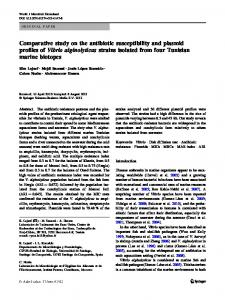
The followings are the amounts of construction materials derived from the material take-offs of the reinforced concrete water tanks designed, for the various capacities chosen. Tank Capacity (m3)
Table 6: Amount of Reinforcements in kilograms Rectangular (kg) Circular (kg)
10 30 90 140 170
1875
1045
3775
3115
17050
11555
26500
17850
32275
19950
26
Comparative Study on the Design of Elevated Rectangular and Circular Concrete Water Tanks
35000
Amount of Reinforcement (Kilograms)
30000
25000
20000
Rectangular Circular
15000
10000
5000
0 10
30
90
140
170
Tank Capacity (cubic metres)
Figure 4.1: Amount of Reinforcement Against Tank Capacity
Tank Capacity, (m3)
Table 7: Amount of Concrete in cubic metres Rectangular, (m3) Circular, (m3)
10
9
5
30
22
15
90
92
43
140
130
64
170
170
80
27
Comparative Study on the Design of Elevated Rectangular and Circular Concrete Water Tanks
180
Amount of Concrete (cubic metres)
160
140
120
100
Rectangular Circular
80
60
40
20
0 10
30
90
140
170
Tank Capacity (cubic metres)
Figure 4.2: Amount of Concrete Against Tank Capacity
Tank Capacity, (m3)
Table 8: Amount of Formwork in square metres Rectangular, (m2) Circular, (m2)
10
51
20
30
119
59
90
520
200
140
750
255
170
925
328
28
Comparative Study on the Design of Elevated Rectangular and Circular Concrete Water Tanks
1000
Amount of Formwork (square metres)
900
800
700
600
500
Rectangular Circular
400
300
200
100
0 10
30
90
140
170
Tank Capacity (cubic metres)
Figure 4.3: Amount of Formwork Against Tank Capacity
IV.
DISCUSSION
From the above outputs, it could be deduced that as the capacities increase, the amounts of materials for the structure also increase. But, a rather non-perfect proportionality resulted; that is, a proportional increase in the capacity would not, necessarily lead to a proportional increase in any of the materials required. Moreover, the quantities of materials needed for the rectangular water tank were constantly more than those needed for the circular water tank, at each varied capacity. Furthermore, assessing the relative reductions in the amounts of materials for the circular tanks when compared with those of rectangular tanks, it could be deduced that if the relative ease of putting up the shuttering; that is the formwork, would be significantly more challenged in the construction of the circular tanks, their presumed material-quantity advantage could be given up for a selection of rectangular tanks (though with potential increase in materialrequirements). This could be considered if the said reduction in materials is relatively small or bearable. But, the final choice would depend on the client‟s desire and the pieces of advice of the professional(s) taking up the job.
V.
CONCLUSION
Generally, the construction material-outputs for all water tank capacities would be based on the choice of the design considerations, with the sizes of their structural elements. Hence, there exists the possibility of having an equal-capacity and similar geometrically shaped water tanks but with some measurable difference in material requirements. For instance, a tank wall designed as a cantilever would come up with a relatively difference material-quantity when compared with its material requirements, if designed as a two-way spanning wall, (as for rectangular tank) or ring (or hoop) wall, (as for circular tank). Also, it can be clearly seen that material needed for the construction of rectangular water tank is comparatively more than those required for circular ones but ease of construction is more difficult in circular water tank as compared to that of rectangular water tanks. Hence, it could be concluded that the outcome of tank design and the possible cost implication of its material requirements- coupled with the relative ease of construction, would basically influence the choice of what geometric shape would be considered for the proposed water tank of any capacity -although, some other factors must still be assessed.
29
Comparative Study on the Design of Elevated Rectangular and Circular Concrete Water Tanks REFERENCES [1]. [2]. [3]. [4]. [5]. [6]. [7]. [8]. [9]. [10]. [11]. [12]. [13]. [14]. [15]. [16]. [17]. [18]. [19]. [20]. [21].
Anchor, R. D. (1981) “Design of Liquid-Retaining Concrete Structures”. London. Surrey University Press. Anchor, R. D. (1992) “Design of Liquid-retaining Concrete Structures”. Second Edition. London. Edward Arnold. BS 8007 ( 1987) Code of Practice for Design of Concrete Structures for Retaining Aqueous Liquids. BS 8110: Part 1 (2007) Code of Practice for Design and Construction- Structural Use of Concrete BS 8110: Part 1 (1997) Code of Practice for Design and Construction- Structural Use of Concrete. Charles, J. (2007) “Longtime Emblems of City Roofs, Still Going Strong” , The New York Times. Durgesh, C. R. (2001) “Performance of Elevated Tanks in Mw 7.7 Bhuj Earthquake”. Department of Civil Engineering, Indian Institute of Technology, India. Elliott, D. (2006) “Wondering About Water Towers” New York Times. Gray, W. S. and Manning, G. P. (1964) “Water Towers, Bunkers, Silos and Other Elevated Structures”. London. Concrete Publications Limited. Ludwig, A. (2008) “Tanks, Cisterns, Aquifers, and Ponds. For Domestic Supply, Fire and Emergency Use-Includes How to Make Ferrocement Water Tanks‟. www.oasisdesign.net Manning, G. P. (1967) “Reservoirs and Tanks‟. London. Concrete Publications Limited. Oyenuga, V. O. (2005) “Simplified Reinforced Concrete Design- A Consultant/Computer-based Approach‟‟. Lagos. Asros Limited Pall, A. and Pall, R. T. (2004) “Performance-Based Design Using Pall Friction Dampers- An Economical Design Solution”. Paper No. 1955. 13th World Conference on Earthquake Engineering. Canada. Patentscope (1998) “Construction of Liquid Retaining Structures”. www.wipo.int/patentscope/en/ Pathak, K. K. and Agarwal, R (2003) “Cost Prediction of Overhead Water Tanksusingartificial Neural Networks”, IE (I) Journal , Vol. 84, pp. 153 – 158. Rao M L N (2000) Effect of confinement on ductility of RC hollow circular columns, a masters' thesis submitted to Dept. of Earthquake Eng, Univ. of Roorkee, Roorkee, India. Reynolds, C. E. and Steedman, J. C. (1988) “Reinforced Concrete Designer‟s Handbook”. Tenth Edition. London. E & FN Spon. Shirima L.M. ( 1996) “Reinforced Blockwork Water Storage Tanks- Reaching The Unreached: Challenges For The 21st Century”, 22nd WEDC Conference, New Delhi. Slater, W.M. (1985) “Concrete Water Tanks in Ontario”. Canadian Journal of Civil Engineering, Toronto. Unified Facilities Criteria (2005) “Structural Design Criteria. For Structures Other Than Buildings” UFC 3-320-05A.
30