...
, {marcioft, mdm}@mackenzie.br ... The OFDM systems divide the available band- ... Block diagram o
Comparing single and multiple carrier schemes using channel coding Daniel L. Hatae, F´abio C. Zottino, Marcio Eisencraft, Magno T. M. Silva, and Maria D. Miranda Mackenzie Presbyterian University S˜ao Paulo, Brazil {daniel.hatae, magnotmsilva}@gmail.com,
[email protected], {marcioft, mdm}@mackenzie.br
Abstract— Recently, a comparison between OFDM (Orthogonal Frequency Division Multiplex) and single carrier with fractionally DFE (Decision Feedback Equalizer) was presented in the absence of channel coding. In this paper, we extend this comparison, considering convolutional coding. Rice and Rayleigh channel models limited to six echoes are assumed in the simulations. Index Terms— OFDM, Decision Feedback Equalizer, fractionally equalizers, channel coding.
T
I. I NTRODUCTION
HE transmission and reception techniques are the main differences among the digital TV standards in each country. The ATSC (Advanced Television Systems Committee) is responsible for the American terrestrial digital TV standard, which considers a single-carrier transmission scheme [1]. The European and Japanese standards, known respectively as DVB-T (Digital Video Broadcasting Terrestrial) and ISDB-T (Integrated Services Digital Broadcasting - Terrestrial), use a multiple-carrier transmission scheme, known as COFDM (Coded Orthogonal Frequency Division Multiplex) [2], [3]. One of the most suited reception techniques for single-carrier uses the Decision Feedback Equalizer (DFE). When compared to Linear Transversal Equalizer (LTE), DFE presents a more favorable tradeoff between computational cost and efficient behavior for channels with severe intersymbol interference [4]. The superiority of DFE with respect to LTE also occurs in the fractionally space. The third and the fourth receiver generations of ATSC digital TV standard consider the fractionally DFE with double symbol transmission rate [5], [6]. Motivated by the recent Brazilian digital TV standard definition, a comparison between single carrier and OFDM, in the absence of channel coding, was presented in [7]. In this case, single-
carrier transmission scheme with the fractionally DFE presents equivalent or even better performance when compared to OFDM. Since channel coding provides better performance in both transmission techniques, we extend, in this paper, the comparison of [7], considering convolutional coding and the soft decision Viterbi algorithm decoding [8]. The paper is organized as follows. In Section II, the most important aspects of problem formulation, considering OFDM, single carrier using DFE, and channel coding are revisited. Simulation results and concluding remarks are presented respectively in sections III and IV. II. P ROBLEM F ORMULATION A. OFDM Systems The OFDM systems divide the available bandwidth into N subcarriers. A spectrally and computationally efficient method to put data on the sub-carriers uses the inverse Fast Fourier Transform (iFFT). The addition of cyclic prefix allows that the linear convolution with the channel can be considered as a circular convolution [9], [10]. In the receiver, inverse operations remove the cyclic prefix and convert the data from frequency to time domain. Channel Coding is important to spread the information over multiple subcarriers. This ensures frequency diversity and improves the OFDM performance [10]. A block diagram of a typical OFDM system is shown in Figure 1. In order to compensate the channel effect, channel estimation techniques must be considered, using pilot subcarrier information [11]. The most used methods are the Least Squares (LS) and the Minimum Mean Square Error (MMSE) [9], [12]. After the channel estimation at the pilot subcarrier frequencies, an interpolation method is used to obtain the channel response at the other subcarrier frequencies.
Data Output
Data Input
η1 (n)
a ( n)
Cp (z)
decoding
encoding
encoding
S/P
u p ( n)
η 2 ( n)
ui (n)
Ci ( z )
P/S FFT
P/S
S/P
CP
CP
y f ( n)
Fig. 1. Block diagram of a typical COFDM system; CP: Cyclic Prefix.
B. Decision Feedback Equalizer Figure 2 shows a communication system model with oversampled DFE, denoted by DFE-T /2. The i.i.d. signal a(n) is encoded and transmitted through an unknown communication channel, modeled by the subchannels Cp (z) and Ci (z), whose transfer functions are given by Cp (z) = h0 + h2 z −1 + · · · + h2N −2 z N −1 Ci (z) = h1 + h3 z −1 + · · · + h2N −1 z N −1 ,
being h0 , h1 , · · · , h2N −1 obtained from the sampling of continuous time channel model with twice the symbol rate. The output channel signals, up (n) and ui (n), suffer intersymbol interference and noise effects. In the receiver, these signals are filtered by Fp (z) and Fi (z), each one with Mf /2 coefficients, forming the oversampled feedforward filter. The past decisions are fed back and filtered by an FIR feedback filter B(z) with Mb coefficients, obtaining the output signal yb (n). Then, a linear combination of the filters’ outputs enters to the decision device. DFE and channel coding must mitigate the channel effects and recover the signal a(n) for some delay τd . The oversampling is explained in details in [13] an its use in DFE was considered, for example, in [6] and [14]. C. Channel Coding We consider the convolutional coding and the soft decision Viterbi decoding. The convolutional encoding can be implemented by shift registers and modulo-2 adders, as shown in Figure 3 for a
Decision device
y ( n)
decoding
z −1
yb (n)
Channel
Fi ( z ) Feedforward filter
Channel
iFFT
Fp ( z )
aˆ ( n −
d
)
Delay
B( z ) Feedback filter
Fig. 2. Communication system model with oversampled Coded DFE.
coding rate of 1/2. This is one of the most applied convolutional codes [9]. It has a single data input and two outputs Ai and Bi , which are interleaved to form the coded output sequence { A1 B1 A2 B2 . . . }. The shift register taps are often specified by the corresponding generator polynomials [8], [9]. Decoding of convolutional codes is often performed by soft decision Viterbi decoding, which is an efficient way to obtain maximum likelihood estimate of the encoded sequence. A detailed description of this technique is presented, for example, in [8].
Output data Ai Input data
T
T
T
T
T
T
Output data Bi Fig. 3. Block diagram of a convolutional code with length 7, rate 1/2, and generator vectors {Ai , Bi } = {131, 171} octal.
III. S IMULATION
RESULTS
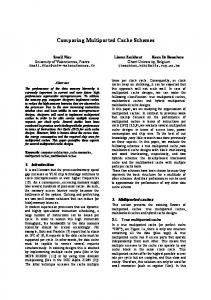
In the simulations, we consider the transmission of binary signals (BPSK - Binary Phase Shift Keying) through the channels Brazil A and Brazil D, whose impulsive response non-null coefficients and magnitude response are shown respectively in Table I and in Figure 4. The channel Brazil A represents a typical reception by external antenna and Brazil D by internal antenna, presenting more difficult equalization. They were obtained from Rice and Rayleigh
theoretical models and have been used as reference in several studies for evaluation and improvement of existing transmission systems (see e.g [6], [15][18]). TABLE I I MPULSIVE R ESPONSE OF THE CONSIDERED CHANNELS . Brazil A
` h`
0 2 25 34 66 67 1,00 0,20 0,15 0,18 0,21 0,15
Brazil D
` h`
2 7 25 34 66 67 0,99 0,65 0,74 0,86 1,00 0,72
a) Brazil A
20
|H(ejω)| (dB)
10 0 −10 −20 −30
0
0.2
0.4
ω/π
0.6
0.8
1
0.8
1
b) Brazil D
20
|H(ejω)| (dB)
10 0 −10 −20 −30
0
0.2
0.4
ω/π
0.6
Fig. 4. Magnitude response of the channels Brazil A and Brazil D.
In the OFDM system, we consider equispaced subcarriers, 8K mode, a cyclic prefix of N/16, and linear interpolation. The channel is estimated with the LS method. In the single carrier with DFE, we consider Mf = 16 coefficients in the feedforward filter and Mb = 48 coefficients in the feedback filter. These coefficients are adapted with the LMS (Least Mean Square) algorithm, assuming the step-size µ = 0, 001. In both schemes, we assume convolutional coding with the generator vectors {131, 171} octal
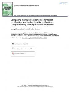
as shown in Figure 3, and the soft decision Viterbi decoding. In the OFDM system, we assume that the pilot subcarriers have twice the amplitude of the information subcarriers. Figure 5 shows Bit Error Rate (BER) curves as function of signal-to-noise ratio (SNR) for the channels Brazil A and D. In Figure 5a) and b), we can observe that, in the absence of channel coding, DFE-T /2 outperforms the OFDM system for Brazil A and D respectively for SNR > 10 dB and SNR > 16 dB. However, for lower SNR, the OFDM system offers some advantages for Brazil D, whose equalization is more difficult. Considering Figure 5-c) and d), that is, using channel coding, both systems present better performance, mainly for Brazil A. Coded DFE-T /2 outperforms COFDM system for higher SNR. It is relevant to note that for Brazil D and SNR < 16 dB, the distance between CDFE-T /2 and COFDM is greater than that of the case without channel coding. For lower SNR, COFDM presents advantages in relation to single carrier. In this case, the performance of CDFE-T /2 is worse than that of DFE-T /2 without channel coding. Due to low SNR, the coding path selected in the trellis diagram contributes to the degeneration of single carrier performance. BER curves for the AWGN channel are also showed in the figure. We can verify that COFDM presents better performance than Coded Single Carrier (CSC) for a channel without intersymbol interference. We also analyse the influence of the amplitude of the OFDM pilot subcarriers. Through simulations, we observe that the effect of the pilots’amplitude is not very meaningful for the channels Brazil A and D. On the other hand, the choice of this amplitude becomes important for the AWGN channel, as shown in Figure 6. In the presence of channel coding, to obtain the best OFDM system performance, the pilot subcarriers should have twice the amplitude of the information subcarriers. For the factor 4, the performances of COFDM and coded single carrier are the same, but worse than the case of the factor 2. IV. C ONCLUSIONS From the simulations, we can conclude that the effect of channel coding is less evident for channels with severe intersymbol interference. Moreover, single carrier with fractionally DFE outperforms multiple carrier system with or without channel coding for high SNR. On the other hand, COFDM presents some advantages for low SNR and for the AWGN channel.
a) Brazil A
0
DFE−T/2 OFDM
10
−2 −3 −4
0
5
−3
−5
20
0
5
10 15 SNR (dB)
−3 −4
25
COFDM − Brazil D COFDM − AWGN CDFE−T/2 − Brazil D CSC − AWGN
−1
−2
20
d)
0
10
10
15
COFDM − Brazil A COFDM − AWGN CDFE−T/2 − Brazil A CSC − AWGN
−1 log (BER)
10 SNR (dB) c)
0
−5
−2
−4
log (BER)
−5
DFE−T/2 OFDM
−1 log (BER)
10
log (BER)
−1
b) Brazil D
0
−2 −3 −4
0
5
10 SNR (dB)
15
20
−5
0
5
10 15 SNR (dB)
20
25
Fig. 5. Decimal logarithm of BER for a) Brazil A without channel coding b) Brazil D without channel coding, c) Brazil A and AWGN with channel coding, and d) Brazil D and AWGN with channel coding
0
COFDM Pilot = 1 COFDM Pilot = 4/3 COFDM Pilot = 2 COFDM Pilot = 3 COFDM Pilot = 4 CSC
10
log (BER)
−1 −2 −3 −4 −5
0
2
4 SNR (dB)
6
8
Fig. 6. The influence of the of the amplitude of the OFDM pilot subcarriers.
R EFERENCES [1] ATSC Digital Television Standard, ATSC Standard A/53, May 21th, 2004. [2] ETSI, “Digital Video Broadcasting (DVB); Framing structure, channel coding and modulation for digital terrestrial television,” Standard ETSI EN 300 744 v1.4.1, European Telecommunications Standards Institute, Jan. 2001.
[3] ARIB STD-B31 V. 1.2, “Transmission System for Digital Terrestrial Television Broadcasting ARIB Standard,” Association of Radio Industries and Businesses, Jan. 24th , 2002. [4] M. Ghosh, “Blind decision feedback equalization for terrestrial television receivers,” Proceedings IEEE, v. 86, p. 2070-2081, Oct. 1998. [5] R. A. Casas, “An integrated VSB/QAM/NTC/BTSC receiver: recent advanced in television designed”, Proceedings of the 53th Annual IEEE Broadcast Symposium, Oct. 2003. [6] L. Qin et al. “Fractionally Spaced Adaptive Decision Feedback Equalizers with Applications to ATSC DTV Receivers,” IEEE Transactions on Consumer Electronics, v. 50, p. 999-1003, Nov. 2004. [7] D. L. Hatae et al., OFDM Systems for Brazilian Digital Television channels, Proceedings of the 10th OFDM Workshop (InOWo’05), Aug. 31st - Sept. 1st, Hamburg, 2005. [8] L. Hanzo, T. H. Liew, and B. L. Yeap Turbo Coding, Turbo Equalisation and Space-Time Coding for Transmission over Fading Channels, John Wiley & Sons, 2002. [9] R. van Nee and R. Prasad, OFDM for wireless multimedia communications, Artech House Publishers, Boston, 2000. [10] L. V. Perre, J. Tubbax, and, H. De Man, “A single-carrierOFDM comparison for broadband wireless communication,”, Proceedings of ICASSP 2004, v. II, pp. 329-332, May 2004.
[11] S. G. Kang, Y. M. Ha, and E. K. Joo, “A comparative investigation on channel estimation algorithms for OFDM in mobile communications,” IEEE Trans. On Broadcasting, v. 49, n. 2, p. 142-149 , June 2003. [12] O. Edfors, “Low-complexity algorithms in digital receivers,” Doctoral Thesis, Lulea University of Technology, Lulea, Sept. 1996. [13] J. R. Treichler, I. Fijalkow, and C. R. Johnson Jr. “Fractionally spaced equalizers,” IEEE Signal Processing Magazine, p. 65-81, May 1996. [14] L. L. Szczecinski and A. Gei, “Blind decision feedback equalisers, how to avoid degenerative solutions,” Signal Processing, v. 82, p. 1675-1693, 2002. [15] SET/ABERT, ”Digital Television Systems - Brazilian tests - Final Report Part 1,” Relat´orio de Testes do Grupo SET/ABERT, ANATEL, S˜ao Paulo, May 2000. [16] ITU Radiocommunication Study Groups, “Guidelines and techniques for the evaluation of DTTB systems,” ITU-R Document 6E/TEMP/131-E, Mar. 2003. [17] Y. Wu et al., “An ATSC DTV receiver with improved robustness to multipath and distributed transmission environments,” IEEE Transactions on Broadcasting, v. 50, n. 4, p. 32-41, Mar. 2004. [18] Z. Yang et al. “A coding and Modulation scheme for HDTV services in DMB-T,” IEEE Transactions on Broadcasting, v. 50, n. 4, p. 26-31, Mar. 2004.