Ethernet emerges with the promise to integrate real-time and best-effort traffic ... over a shared bus, when using group communication. 1. Introduction ... Current Ethernet â in contrast to FlexRay ..... tion 3.0 E1, Karlsruhe, Germany, Oct 2009.
Comparing Time-Triggered Ethernet with FlexRay: An Evaluation of Competing Approaches to Real-time for In-Vehicle Networks Till Steinbach, Franz Korf, Thomas C. Schmidt Department of Computer Science Hamburg University of Applied Sciences, Germany {till.steinbach, korf, schmidt}@informatik.haw-hamburg.de
Abstract FlexRay is considered the next generation state-of-theart technology for in-car networks, while time-triggered Ethernet emerges with the promise to integrate real-time and best-effort traffic into one homogeneous backbone. This paper contributes a competitive analysis of FlexRay and time-triggered Ethernet. By showing that it is possible to transfer a fully utilized FlexRay system to a system based on time-triggered Ethernet, it is demonstrated that time-triggered Ethernet is a suitable replacement of current in-vehicle bus-systems. Further it is shown that a switched system has advantages in bandwidth utilization over a shared bus, when using group communication.
1. Introduction Today’s vehicles are complex distributed real-time systems with a high demand of broadband communication links. In such systems, the communication flow between modules has significant impact on safety, reliability, and comfort of the vehicle. New proposals for automotive systems require supervising control units for specific tasks that are connected across a backbone network. These networks need to carry heavy load, while keeping message delays predictable. Currently, FlexRay [1] gains importance as state-ofthe-art technology for a backbone of in-vehicle networks designed to meet hard real-time constraints. It is the first automotive protocol that allows offline scheduling for time-triggered traffic and randomly occurring eventtriggered data in parallel. For each message, the predefined schedule defines an exact, system-wide timestamp at which this message will be visible on the FlexRay bus. FlexRay complies to the enhanced temporal requirements of the new vehicle chassis control applications, which could not be satisfied with busses like CAN [2]. A new approach to in-vehicle networks is based on Ethernet, which has proven to be a flexible, highly scalable protocol. Current Ethernet — in contrast to FlexRay — is a technology based on switching that allows to increase the amount of traffic simultaneously transferred by using segregated communication in groups. However, due to its randomised access and best effort approach, it does not provide reliable temporal performance bounds. There
are many attempts to overcome those obstacles like tokenbased, bandwidth-limiting or time-triggered systems. For a smooth integration into current designs, this paper focuses on time-triggered Ethernet systems [3]. The results of this paper are based on the time-triggered Ethernet (TTEthernet) specification by TTTech [3] that is currently proposed for standardisation by the Society of Automotive Engineers [4]. Nonetheless, the results are mostly transferable to other time-triggered Ethernet protocols, as well. TTEthernet supports several traffic classes with different qualities for the various real-time related metrics. This offers the chance to decrease the heterogeneity of today’s in-vehicle communication systems, that consist of several CAN, FlexRay or MOST [5] busses connected via gateways, by aggregating several systems into one Ethernet based communication network. This paper offers a competitive analysis of FlexRay and TTEthernet by showing the differences and commonalities of both technologies. Based on a mathematical model, the general eligibility of TTEthernet for in-vehicle applications is shown in the scenario, when a fully utilised FlexRay system is replaced by a time-triggered Ethernet substitute. Further, it is discussed that a switched system has advantages in utilization, when using group communication. Besides general differences like components and topology, the analysis covers comparisons for real-time relevant metrics like latency, jitter and bandwidth. The remainder of this paper is organised as follows. In section 2 related work and the base techniques are introduced. Section 3 compares the performance of the protocols under common real-time related metrics. Finally, section 4 concludes and gives an outlook.
2. Background Related Work In process automation, there is already a large collection of products that rely on Ethernet and promise real-time communication. For in-vehicle communication, the use of Ethernet is a novelty. In general, there are token-based, bandwidth limiting and time-triggered protocols to ensure a predictable delay and jitter in packet delivery and prevent real-time packets from simultaneously traversing a switch interface or line card. Time-triggered protocols are well known within the automotive industry and based on previous experiences
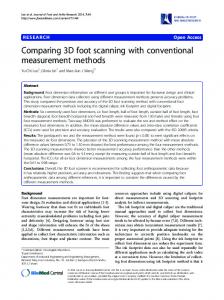
cycle i+1 network idle time
static segment
...
symbol window
static slot n
...
static slot n
static slot 1 static slot 2 static slot 3 static slot 4 static slot 5
dynamic segment
static slot 1 static slot 2 static slot 3 static slot 4 static slot 5
cycle i static segment
Figure 1. Composition of FlexRay cycle with TTCAN [6] and FlexRay. Therefore they are in focus of this paper. All senders in time-triggered protocols are required to operate in a synchronised way. A schedule defines permissible transmission times. In process automation, these protocols dominate deployment. Examples are Profinet [7], SynqNet [8] or RTnet [9]. FlexRay FlexRay has been developed by the FlexRay consortium [1] starting in the year 2000. Especially new requirements by the chassis control led to a system with synchronisation and a predefined schedule that allows operation without collision and thus lower bounds for latency and jitter. The FlexRay protocol is centred about periodic cycles. Each cycle is composed of a static and a dynamic segment (see figure 1), governed by different bus access policies. For time-triggered communication, each node is assigned to communication slots in the static segment. Delivery depends on a global time across all participants and thus a precise synchronisation. The dynamic segment is intended for priorised event-triggered communication. It is not intended for hard real-time communication and is therefore not subject of this paper. FlexRay allows for bus, star or mixed topologies and defines two separate channels for transmission. Both can be used simultaneously, leading to a total bandwidth of 20 Mbit/s or with one channel for redundancy at 10 Mbit/s. Time-Triggered Ethernet TTEthernet [3] combines standard Ethernet based best-effort network traffic and hard real-time communication on the same infrastructure. It adds, similar to FlexRay, time slotting to standard switched Ethernet. On layer 2 a global out of band schedule that defines a plan for transmission or relaying in the time-triggered domain, is shared among all TTEthernet participants and switches. The TTEthernet specification defines a failsafe synchronisation protocol to distribute a global time among all senders. Besides the timetriggered traffic, TTEthernet offers rate-constrained traffic based on the AFDX-Protocol [10] for communication with less rigid temporal requirements, similar to the messages in FlexRays dynamic segment and best-effort traffic. TTEthernet relies on switched Ethernet. Any topology is formed of switches that relay the messages. Redundancy can be achieved by multiple redundant channels.
3. Comparison Based on the configuration given in table 1, timetriggered functionality of FlexRay and TTEthernet are compared. This scenario represents the maximal topology of FlexRay [11]. Analysis of other scenarios that base on current car networks is subject of upcoming work. The framework given here can be adapted to these topologies.
Table 1. Sample configuration FlexRay TTEthernet bus speed (VB ) 10 Msbit 100 Msbit max payload size (lP ) 254 Byte 1500 Byte min payload size (lP ) 1 Byte 46 Byte topology two active stars/switches wire length (lW ) 72 m divergence of quartz (∆Q ) 200 ppm cycle time (tC ) 16 ms Latency Since FlexRay is a wired bus, latency consists of the signal runtime from sender to receiver and the transfer time for the message. Equation 1 calculates the signal runtime tS for the FlexRay sample configuration. It is composed of the propagation delay of the wire tW D , maximum delays for sending and receiving at bus drivers tDD , and the product of the number of active stars nS and their maximum delay tSD . Considering our sample configuration with a wire length of lW and a topology with two active stars nS we get a delay of tS = 1420 ns. tS = tW D ∗ lW + 2 ∗ tDD + tSD ∗ nS (1) ns ∗ 72 m + 2 ∗ 100 ns + 250 ns ∗ 2 = 10 m = 1420 ns The transfer time depends on frame size and bus speed. In FlexRay, the frame size lF is composed of the transmission start sequence lT S , the frame start sequence lF S , the protocol overhead lP O , the frame end sequence lF E and the payload lP . For synchronisation of FlexRay controllers each byte is encoded in 10 bit. The transmission start sequence must fill the time needed to change state from idle to active at sender, receiver and at each active star and the time to transmit one bit. For the sample configuration, a sequence of lT S = 15 bits is suitable. lF = lT S + lF S + lP O + lP ∗ 10 bit + lF E (2) = 15 bit + 1 bit + 80 bit + lP ∗ 10 bit + 2 bit = 98 bit + lP ∗ 10 bit lF min = 98 bit + (1 ∗ 10 bit) = 108 bit
(3)
lF max = 98 bit + (254 ∗ 10 bit) = 2638 bit
(4)
With the bit time tb = tT can be calculated. tT = lF ∗ tb
1 VB
= 0.1
µs bit ,
the transfer time
(5) µs tT min = 108 bit ∗ 0.1 = 10.8 µs (6) bit µs tT max = 2638 bit ∗ 0.1 = 263.8 µs (7) bit Together with the signal runtime tS = 1420 ns a total latency between 12.2 µs and 265.2 µs was calculated. Latency in TTEthernet is caused by switching delays. TTTech indicates the switching delay tSD for their current implementation between 1 µs and 2.4 µs. Total latency can be calculated as the sum of propagation delay tW D ∗ lW , transmission time lF ∗ tb , and the sum of each switch delay between sender and receiver. Due to store and forward switching the transmission time must
be added for each switch. The bit time for 100 Mbit/s is µs . tb = V1B = 100 1M bit = 0.01 bit s ns X tL = tW D ∗ lW + (ns + 1) ∗ lF ∗ tb + tSDi (8) i=1
The time for message transmission lF ∗ tb ranges from 5.8µs for the smallest Ethernet frame to 122µs for a frame with maximum payload. The latency for TTEthernet tL for the topology with two switches can be approximated by equation 8 with 24µs to 372µs. Jitter We calculate an upper bound of possible jitter for FlexRay by evaluating the maximum time difference in network traversal. The receiving node can experience jitter at the scale of clock deviations between the nodes. Since FlexRays clock synchronisation takes place after each cycle, equation 9 calculates the drift with the precision of the quartz ∆Q and the cycle time tC . 2 ∗ t C ∗ ∆Q (9) (1 − ∆Q ) 2 ∗ 16 ms ∗ 0.0002 = = 6.4 µs 1 − 0.0002 In TTEthernet each forwarding instance in the path of a message has a schedule for transmission time. The latency can vary when the local clocks of sender and forwarding switches drift apart. The longest runtime between sender and receiver is given when the clock of the sender gains and the clock of the forwarding switch looses. The shortest runtime is obtained when the senders clock looses and the forwarding switches clock gains. Accordingly, the maximum jitter for TTEthernet messages tJmax can be calculated as twice the maximum clock deviation tDmax . tJmax = 2 ∗ tDmax (10) tJmax =
TTTech indicates tDmax for the current TTEthernet implementation in the low unary microsecond span. Hence the jitter bounds are comparable (see table 2). Bandwidth Since only real-time communication is of interest for the comparison, the optional dynamic segment and symbol window of FlexRay are omitted to maximise bandwidth for static transmission slots. The size of the static segment tS can then be calculated as the cycle time tC without the network-idle time tI (see figure 1). tS = tC − tI (11) = 16000 µs − 12 µs = 15.988 ms To calculate the static slot size tST , the channel idle delimiter lCI and the action point offset tA are needed. The action point offset allows inaccuracies in synchronisation. Based on the precision, an action point offset of tA = 4 µs is chosen. To account for the optimal ratio of payload to protocol overhead, the largest payload of lP = 254 Byte is chosen. This leads to a frame size of lF max = 2638 bit, as shown in equation 4. tb is the time needed to transfer one bit at 10 Mbit/s. In FlexRay the slot size is defined in macroticks (MT). In the sample configuration one
macrotick is tM T = 1µs. (lF max + lCI ) ∗ tb + tW D ∗ lW tST = 2 ∗ tA + (12) tM T ∗ (1 − ∆Q ) = 2 ∗ 4 MT µs (2638 bit + 11 bit) ∗ 0.1 bit + 0.9 µs + 1 µs ∗ (1 − 0.0002) = 8 M T + 265 M T = 273 M T With equation 13, the maximum number of slots nS can be calculated. � � � � tS 15988 M T = 58 (13) nS = = tST 273 M T Equation 14 calculates the net bandwidth B with the maximum payload of lP = 254 Byte for a fully utilised FlexRay bus in the sample configuration. 58 ∗ 254 ∗ 8 Bit n S ∗ lP = (14) B= tC 16 ms M bit = 7.366 s To show the feasibility of embedding the traffic of the sample FlexRay configuration, TTEthernet is configured with the same cycle time tC , number of slots nS and payload size lP . Together with the Ethernet protocol overhead (header, preamble and trailer) the total frame size evaluates to lF = 280 Byte. The time between two consecutive frames tA is extended from the standard Ethernet inter frame gap of 0.96 µs to tA = 4 µs to allow inaccuracies in synchronisation. With equation 15, the slot size tST for one TTEthernet real-time message can be calculated. For the desired nS = 58 slots this results in a total time for real-time communication of tS ≈ 1.764 ms. The TTEthernet cycle of the sample configuration is utilised with approximate nC = 11%. As expected due to bus speed the FlexRay real-time traffic can be embedded in TTEthernet. lF tST = + 2 ∗ tA (15) VB 280 ∗ 8 Bit = + 2 ∗ 4 µs = 30.4 µs 100 Msbit tS = nS ∗ tST = 58 ∗ 30.4 µs ≈ 1.764 ms (16) Discussion Figure 2 shows the available number of realtime slots for frames with payload sizes between 1 Byte and the maximum payload size, as derived from the priviously defined parameters. Based on the available slots, the possible bandwidth for FlexRay and TTEthernet can be evaluated as is shown in figure 3. Due to the overhead of both protocols, a gain of bandwidth can be seen for packets with higher payload. Due to the larger protocol overhead and padding of small Ethernet frames, TTEthernet benefits especially from frames bigger than the minimum frame size. The padding can be seen in figure 2 as a constant interval. For the same interval, the increase of bandwidth is linear (figure 3). FlexRays bandwidth can be directly read off the given plot, since the static segment only allows for one fixed frame size at all static slots. TTEthernet allows to vary frame sizes for all messages. This leads to a mixed calculation over all used frame sizes.
1 0 0
8 0 0 6 0 0 4 0 0 2 0 0 0
T T E th e rn e t F le x R a y
9 0
T T E th e rn e t F le x R a y
1 0 0 0
8 0
B a n d w id th [M b it/s ]
A v a ila b le R e a ltim e S lo ts [# ]
1 2 0 0
7 0
1 0
6 0
9 8
5 0 7 6
4 0 5
3 0 4 3
2 0 2 1
0
1 0 2 0 0
4 0 0
6 0 0
8 0 0
1 0 0 0
P a y lo a d [B y te ]
1 2 0 0
1 4 0 0
0
0
0
2 0 0
4 0 0
0
6 0 0
2 0
8 0 0
4 0
6 0
1 0 0 0
P a y lo a d [B y te ]
8 0
1 2 0 0
1 0 0
1 4 0 0
Figure 2. FlexRay and TTEthernet slots at payload size (16ms cycle)
Figure 3. FlexRay and TTEthernet net bandwidth at payload size (16ms cycle)
Most in-vehicle networks can be partitioned in groups with communication restricted to group members, and messages that are passed only within those groups. While FlexRay is limited to broadcast communication, TTEthernet inherits multicast group communication from the Ethernet standard. As long as the links between the members of different groups remain disjoint, messages can be relayed concurrently. Plotted results therefore reflect the worst case results. For the maximum payload of FlexRay (254 Bytes) we showed that a comparable TTEthernet design is only utilised by approximately 11%, while all messages remain of broadcast type. This corresponds to empirical observations considering the ten times higher bandwidth of 100 Mbit/s Ethernet and the slightly higher protocol overhead. TTEthernet is not offered in a 10 Mbit/s version. Because of the larger protocol overhead, TTEthernet with 10 Mbit/s would only keep up with FlexRay with a certain amount of traffic transmitted in parallel. As shown, latency in TTEthernet is strictly predictable for each time-triggered message, but in general depends on the path from sender to receiver. In contrast to FlexRay, the usable bandwidth is not affected by the latency. Latency remains low as compared with the usual cycle time. Besides the topology, the latency depends on the switching technology and the precision of clock synchronisation. Jitter depends on the precision of clock synchronisation, as well. This holds for both FlexRay and TTEthernet.
thus possible to transfer a FlexRay based in-vehicle network to an Ethernet network. This work defines a basis for further analysis. The calculations given can be adapted for other time-triggered Ethernet techologies. Currently, we simulate TTEthernet in-vehicle networks based on concrete automobile topologies and application data and build a mockup of an invehicle network, based on TTEthernet for measurement and load analysis. Future work will analyse how eventtriggered traffic, segmentation and priority functionalities of Ethernet can guarantee a smooth integration of timetriggered Ethernet systems into current in-vehicle communication infrastructures.
Table 2. Sample configuration results FlexRay TTEthernet latency min. payload 12.2µs 24µs latency max. payload 265.2µs 372µs jitter bounds 6.4µs < 10µs
4. Conclusion & Outlook Real-time Ethernet is an emerging technology for invehicle communication. We have shown by calculations of characteristic FlexRay and TTEthernet scenarios that FlexRay real-time traffic can be embedded in real-time Ethernet. Jitter and latency are comparable (table 2). It is
References [1] FlexRay consortium, “Protocol Specification”, Specification 2.1, Stuttgart, Germany, Dec 2005. [2] International Organization for Standardization, “Road vehicles - Controller Area Network (CAN)”, ISO 11898, ISO, Geneva, Switzerland, 2003. [3] W. Steiner, “TTEthernet Specification”, TTTech Computertechnik AG, Vienna, Austria, Nov 2008. [4] Society of Automotive Engineers, “SAE International”, Warrendale, Pennsylvania, USA. [5] MOST Cooperation, “Protocol Specification”, Specification 3.0 E1, Karlsruhe, Germany, Oct 2009. [6] International Organization for Standardization, “Road vehicles - Controller Area Network (CAN) - Part 4: Time-triggered communication”, ISO 11898-4:2004, ISO, Geneva, Switzerland, 2004. [7] PROFIBUS & PROFINET International, “Profinet”, Karlsruhe, Germany. [8] SynqNet Interest Group, “SynqNet”, Santa Barbara, CA, USA. [9] J. Kiszka and B. Wagner, “RTnet - a flexible hard realtime networking framework”, 10th IEEE Conference on Emerging Technologies and Factory Automation (ETFA 2005), vol. 1, pp. 456–463, 2005. [10] Aeronautical Radio Incorporated, “Aircraft Data Network”, Standard 664, ARINC, Annapolis, MD, USA, 2002. [11] M. Rausch, FlexRay: Grundlagen, Funktionsweise, Anwendung, Carl Hanser Verlag, M¨unchen, 2008.