sequences when a high robust delay fault coverage is targeted. In this paper, we first ... guaranteed if there is no delay fault in the circuit. A large number of ...
Comparison Between Random and Pseudo-Random Generation for BIST of Delay, Stuck-at and Bridging Faults Patrick GIRARD Christian LANDRAULT Serge PRAVOSSOUDOVITCH Arnaud VIRAZEL Laboratoire d’Informatique, de Robotique et de Microélectronique de Montpellier UMR 5506 Université Montpellier II/CNRS - 161, rue Ada, 34392 Montpellier Cedex 05, France Email: @lirmm.fr - URL: http://www.lirmm.fr/~w3mic
Abstract The combination of higher quality requirements and sensitivity of high performance circuits to delay defects has led to an increasing emphasis on delay testing of VLSI circuits. As delay testing using external testers requires expensive ATE, built-in self test (BIST) is an alternative technique that can significantly reduce the test cost. The generation of test patterns in this case is usually pseudorandom (produced from an LFSR), and it has been proven that Single Input Change (SIC) test sequences are more effective than classical Multiple Input Change (MIC) test sequences when a high robust delay fault coverage is targeted. In this paper, we first question the use of a pseudo-random generation to produce effective delay test pairs. We demonstrate that using truly random test pairs (produced from a software generation) to test path delay faults in a given circuit produces higher delay fault coverage than that obtained with pseudo-random test pairs obtained from a classical primitive LFSR. Next, we show that the same conclusion can be drawn when stuck-at or bridging fault coverage is targeted rather delay fault coverage. A modified hardware TPG structure allowing the generation of truly random test patterns is introduced at the end of the paper.
1.
Introduction
With the ever-increasing complexity and density of present day integrated circuits, the cost of testing has become a significant part of the overall chip costs. Thereby, Built-In Self-Test (BIST) has been proposed as a powerful design for testability technique for addressing the highly complex VLSI testing problems [1]. BIST design includes on-chip circuitry to provide test patterns and to analyze output responses. It can perform the test internal to the chip so that the need for complex external testing equipment is greatly reduced. Using BIST, the test volume can be significantly reduced, and many of the traditional testing problems (low accessibility of internal nodes that increases the test complexity) can be overcome [2]. Another interesting feature of BIST strategies is that they allow at-speed testing of the circuit under test. The test is perform at the nominal operation frequency without
resorting to an external high speed tester that represents an expensive Automatic Test Equipment (ATE) and which additionally does not always have a timing accuracy comparable to the IC internal speed [3]. At-speed testing is becoming an essential part of the testing process of today’s VLSI circuits since it allows to greatly reduce the test time and provides the means to test for delay faults. A delay fault occurs in a circuit when one or more paths in the circuit fail to propagate a signal within the time interval specified by the clock period. Detection of delay faults requires two-pattern tests. An initialization vector is applied and the circuit is allowed to stabilize. Then, the test vector is applied and the circuit outputs are sampled at clock speed. The response is then compared to that of the fault-free circuit to determine the presence or the absence of a delay fault. According to this test scheme, correct operation of a circuit at the intended speed can only be guaranteed if there is no delay fault in the circuit. A large number of techniques for BIST of delay faults have been developed so far [4,5,6,7,8,9]. Their effectiveness can be evaluated from many points of view: the area and performance overhead they introduce, the fault coverage they guarantee, how easily and automatically they can be introduced into the original design structures, etc. Ruling out the possibility to use full deterministic BIST (due to the prohibitive area overhead required to store test pattern pairs), three main approaches for delay fault BIST are possible: exhaustive or pseudo-exhaustive testing, pseudodeterministic testing and pseudo-random testing. The disadvantage of pseudo-exhaustive and pseudodeterministic testing is that the test execution time is fixed and raises exponentially with the number n of inputs of the CUT. Moreover, the number of embedded test pairs in a pseudo-deterministic sequence may be too small to achieve the targeted delay fault coverage within an acceptable area overhead. Pseudo-random testing refers to the application of test patterns that exhibit randomness, but which are generated using special-purpose hardware, and are thus repeatable. Numerous studies have compared Linear Feedback Shift Register (LFSR) and Cellular Automata (CA) efficiencies for pseudo-random testing of delay faults [4,5]. They led to new proposals: GLFSR [6], circular self-test path (CSTP)
designs [7], etc. Weighted pseudo-random testing has also been investigated for BIST of delay faults [8]. From a general point of view, the effectiveness of pseudo-random BIST is a function of the test sequence length. Compared with pseudo-exhaustive and pseudo-deterministic testing, pseudo-random BIST for testing delay faults offers the best tradeoff between fault coverage achieved, test execution time and area overhead. In terms of delay fault coverage, conventional pseudorandom test patterns in which more than one bit change between two consecutive patterns are not efficient to robustly test combinational circuits in a reasonable test time. This fact is what has motivated the development of pseudo-random BIST techniques in which Single Input Change (SIC) test pairs are generated for testing delay faults [8,9]. SIC test pairs are sufficient to detect all robustly detectable path delay faults [10], with a test length shorter than that required with Multiple Input Change (MIC) test pairs [8]. Note that robustness of delay tests is important to guarantee timing correctness of the CUT since it allows to detect a delay fault even in the presence of other delay faults in the circuit. A main problem, however, encountered with SIC TPG designs is that pseudo-random SIC test pairs generated from a classical LFSR are not equally likely to appear during test generation. Actually, the probability distribution of each output signal of the LFSR is the same, i.e. the probability for a zero or a one to appear on a LFSR’s output is 0.5. But on the other hand, the probability distribution of a given transition signal is not the same for each output of the LFSR. This is due to the structural correlation existing between each cell of the LFSR or, in other words, to the linear dependencies of the LFSR. Consequently, some pseudo-random delay test pairs may not appear at the output of a conventional primitive LFSR, thus leading to a delay fault coverage that is under the maximum achievable value. In this paper, we first question the use of a pseudorandom generation to produce effective delay test pairs. We demonstrate that using Random SIC (RSIC) or Random MIC (RMIC) test pairs (produced from a software generation) to test path delay faults in a given circuit produces higher delay fault coverage than that obtained with pseudo-random test pairs produced from a classical primitive LFSR. Next, we show that the same conclusion can be drawn when stuck-at or bridging fault coverage is targeted rather delay fault coverage. A modified hardware TPG structure allowing on-chip generation of truly random test patterns is introduced and briefly discussed at the end of the paper. The rest of the paper is organized as follows. Section 2 gives some preliminary definitions on delay fault testing. Section 3 compares the effectiveness of random and pseudo-random generation to test delay faults. Section 4 extends the results obtained in Section 3 to the case of
stuck-at and bridging fault testing. Section 5 summarizes the work presented and discusses the extension of this study.
2.
Preliminaries
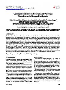
2.1 Basic definitions Correct operation of a circuit at the intended speed requires that any path delay exceeds the value determined by the clock period. This is usually verified by delay testing, using the path delay fault model [10]. In this model, it is assumed that the presence of a delay fault increases the delay along the path. This model represents distributed delays in the circuit, often caused by device parameter variation [11], as well as single isolated failures. This is the main advantage of this model over other existing delay fault models, namely the gate delay fault model and the transition delay fault model [12,13]. However, an important feature of the path delay fault model is that the single fault assumption is no longer realistic since a single defect usually affects a large number of paths. For this reason, a robust test is preferred to detect a path delay fault. A robust test is a test that detects a delay fault regardless of all other delays and delay faults in the circuit [10]. In contrast, a test that detects a fault with the assumption that no other delay fault can exist in the circuit is called a non-robust test. A test for a path delay fault consists of propagating a transition along the target path P = (g0,g1,…,gn), where each gi is a gate except g0 and gn which are the source and the destination of the path respectively (usually an input and an output of the circuit). The inputs of gi other than the output of gi-1 are called side-inputs of gi (or side-inputs of P). Each connection between gi-1 and gi is called an on-input of P. Sensitization conditions for non-robust and robust testability of a path delay fault are as follows. A non-robust test for a rising (or a falling) transition on a path P sets every side-input of P to a final non-controlling value. In a robust test, side-inputs must be at stable non-controlling values (with no static hazards) when on-path inputs have transitions to final controlling values. These conditions are illustrated in Figure 1 for an AND-type logic gate and are described in more details in [10]. X1 S1 i) Robust test
X1: final 1 value S1: stable 1 value
X1 X1 ii) Non robust test
Figure 1: Robust and non-robust test conditions for path delay faults
2.2 Models and experimental conditions As the purpose in this work was not to develop a delay fault simulator to evaluate the fault coverage of the experimented delay test sequences (pseudo-random SIC,
random SIC and MIC test sequences), we used an industrial test evaluation package, TestGen of Synopsys [14], to perform test validations. An important comment on the validation results given in this paper is that the ISCAS’85 circuits family and the biggest ISCAS’89 circuits have not been used in our experiments. This is because the number of path faults in these circuits is too huge, and TestGen is unable to generate the corresponding delay fault dictionaries for fault simulation. For the reader's convenience, we recall in Table 1 the main characteristics of the investigated ISCAS'89 benchmark circuits (full scan version) [15]. Circuit s298 s382 s386 s420 s510 s526 s641 s713 s1238 s1494 s3330 s5378
# inputs 17 24 13 35 25 24 54 54 32 14 172 214
# gates 119 158 159 196 211 193 379 393 508 647 1789 2779
# path faults 462 800 414 682 686 820 2778 6130 3984 1802 9074 18532
Table 1: Characteristics of the investigated ISCAS’89 benchmark circuits
In the delay fault tool suite of the Testgen package, several models are supported for testing delay paths. The conventional non-robust delay fault model is referred to as the weak non-robust delay model in TestGen, and delay fault simulation or test generation from this model is possible. Conversely, the conventional robust delay fault model is also supported by TestGen, but one of the main sensitization constraints in this model (no glitches on the side-inputs when on-path inputs have transitions to final controlling values) is not verified during delay fault simulation or test generation. As a consequence, fault-free results cannot be assured when using such delay fault model with TestGen. The closest delay fault model handled by this tool is the strong non-robust delay fault model, for which the sensitization conditions are the following: in a strong nonrobust test, side-inputs must be at initial and final noncontrolling value when on-path inputs have transitions to final controlling values. The off-path signal may experience a static hazards during the period of observation [15]. Considering these remarks and in order to obtain error-free results, we used the strong non-robust delay model (in addition to the non-robust delay model) as a metric to evaluate the quality of the test sequences generated for testing path delay faults. As the strong nonrobust delay model is very close to the conventional robust delay model (the only difference states in the acceptance of
static hazards on side-inputs when on-path inputs have transitions to final controlling values), this model will be referred to as the pseudo-robust delay model in the sequel. Apart from robust and non-robust testable paths, two other classes of paths have been defined in the literature: functional sensitizable paths and functional redundant paths [16]. Functional redundant paths can never determine the performance of the circuit and do not have to be tested [17]. On the other hand, defects on functional sensitizable paths may degrade the circuit performance when several path delay faults occur simultaneously. Although the number of functional sensitizable paths in a circuit may be not negligible, this model of path delay faults is not handled by TestGen. For this reason, only pseudo-robust and non-robust tests are considered in the rest of this study.
2.3 SIC and MIC test sequences In general, two-pattern tests may vary in multiple bit positions. In this case, they are called multiple input change (MIC) pattern pairs. Test pattern pairs that differ in exactly one bit are called adjacent or single input change (SIC) pattern pairs. Let us now define what a RMIC and a RSIC sequences should be from a theoretical point of view (we assume implicitly the case of equal likelihood of all vectors). Let S=V(1) V(2)…V(l)…V(L) be a test sequence composed of L successive n-bit vectors V(l). Each vector takes a value from the set V={V0,V1, …V2 -1}, where Vj corresponds to the n-bit vector associated with the decimal value j. For example, for n=5, V11=01011, i.e., x1=x3=0 and x2=x4=x5=1. In a RMIC sequence, the probability n Pr[V(l)=Vj] = 1/2 for any l and any j, and the probability Pr[V(l)=Vj] is independent of the values V(i), i=1, …,l-1. In a RSIC sequence, Pr[V(l)=Vj | V(l-1)=Vk] = 1/n iff |ja k|=2 , where a is a non-negative integer (in other words, V(l) differs from V(l-1) by exactly one bit randomly drawn). A delay test consisting of adjacent or SIC vectors is called an adjacency or an asynchronous test. As a single transition is applied at the primary inputs of the CUT in an adjacency test, the probability of delay test invalidation due to hazards or multiple delay faults is greatly reduced. This is one of the main reasons for using such kind of tests. Moreover, SIC test pairs are sufficient to detect all robustly detectable path delay faults [10]. Finally, the universe of pattern pairs n considered for SIC test generation (O(n.2 )) is significantly 2n smaller than that for MIC test generation (O(2 )). Hence, SIC fault coverage can be higher than MIC fault coverage for the same test length [8,18]. n
3.
Comparing random and pseudo-random generation for delay testing
In this section, we demonstrate that using RSIC or RMIC test pairs (produced from a software generation) to test path delay faults in a given circuit produces higher delay fault
coverage than that obtained with pseudo-random test pairs obtained from a classical primitive LFSR. A software random generation is easy to perform thanks to the instruction "random" existing in any programming language. In the C language, this function returns a random 15 32 number ranging from 0 to 2 -1 with a period of 2 . The randomness of the generated values is usually good although there exists some limitations that are fully described in [19]. During software generation, producing a sequence of adjacent or SIC vectors is performed according to the following. First of all, the range of values comprised 15 between 0 and 2 -1 is divided into n intervals, with n being the number of inputs of the CUT. After that, an initial nbits vector is determined or randomly selected. Next, a 15 random number comprised between 0 and 2 -1 is drawn by using the function rand. According to the number returned by this function, the bit in the current vector that corresponds to the selected interval is changed in the new vector. Then, this process is iterated l times, with l being the length of the RSIC test sequence. A set of experiments has been performed to compare the robust delay fault coverage achieved by sequences of RSIC test pairs and sequences of pseudo-random SIC test pairs. RSIC test pairs have been obtained from the software generation process described above. Pseudo-random SIC test pairs have been obtained from an hardware generation process, using a n-stage primitive polynomial LFSR with the seed 100…0 (note that the same initial vector has been chosen for the software random generation). The additional circuitry required to produce single bit changes between vectors has been taken from the SIC TPG design described in [9]. Results of these experiments are reported in Table 2. For each circuit, we first give the test length and the pseudo-robust delay fault coverage provided by the ATPG tool of Synopsys [15] (note that the ATPG tool usually provides MIC test patterns). Circuit s298 s382 s386 s420 s510 s526 s641 s713 s1238 s1494 s3330 s5378
ATPG #patt FC % 688 76.19 1398 88 736 100 1322 100 1366 100 1396 86.3 2778 66.16 4418 22.54 4992 62.2 3518 98.8 15862 89.87 29730 74.02
#patterns ⇒ 68800 139800 73600 132200 136600 139600 277800 441800 499200 351800 158620 297300
RSIC Eff % 91.48 91.19 98.79 66.86 91.11 90.40 76.01 83.72 89.11 94.51 62.28 64.77
SIC [9] Eff % 75.85 77.69 87.92 51.17 75.95 81.50 66.60 72.94 74.94 81.47 14.14 46.18
Table 2: Comparison between pseudo-robust fault coverage of pseudo-random SIC and RSIC
Circuits for which the maximum fault coverage is not achieved (s1238 for example) are circuits containing non-
robust testable paths, functional sensitizable paths or redundant paths. The next column in Table 2 (#patterns) reports the test length for RSIC and pseudo-random SIC testing. This length corresponds to the length of the test sequence produced by the ATPG multiply by 100 (lengthATPG×100). The remaining columns in Table 2 list the pseudo-robust delay fault efficiency (with respect to the ATPG fault coverage) obtained after RSIC generation and pseudo-random SIC generation with the TPG design described in [9] respectively. As can be seen with these results, the pseudo-robust delay fault coverage obtained with RSIC test sequences is always higher than that obtained with pseudo-random SIC test pairs. For some circuits (s1494 for example), the difference in terms of quality between RSIC and pseudo-random SIC testing can be even very important. Consequently, these results clearly illustrate the fact that generating SIC patterns from a random generator provides higher fault coverage than that obtained with SIC patterns generated from a pseudo-random generation. An important additional comment on these results is that the same conclusion can be drawn when i) the coverage of non-robust testable paths is targeted rather than the coverage of robust testable paths, and ii) MIC test sequences are used rather than SIC sequences. To highlight these points, two other sets of experiments were performed and results are given in Table 3 and Table 4. In Table 3, we have reported the results in terms of non-robust delay fault coverage of RSIC and pseudo-random SIC testing. The non-robust fault coverage obtained from the ATPG tool of Synopsys is shown in column 2. The fault efficiency, which is the ratio between the fault coverage achieved and the ATPG fault coverage, is given for RSIC and pseudorandom SIC non-robust test generations. Circuit
ATPG FC %
s298 s382 s386 s420 s510 s526 s641 s713 s1238 s1494 s3330 s5378
78.79 91.75 100 100 100 87.80 71.02 37.13 62.93 98.89 90.94 82.20
#patterns ⇒ 68800 139800 73600 132200 136600 139600 277800 441800 499200 351800 158620 297300
RSIC Eff %
SIC [9] Eff %
100 99.46 100 68.62 100 95.98 80.29 83.84 97.16 100 77.63 67.23
100 100 100 66.22 100 97.64 82.72 87.83 93.55 99.54 17.01 56.95
Table 3: Comparison between non-robust fault coverage of pseudo-random SIC and RSIC
In most cases, the non-robust fault efficiency is higher with RSIC testing. In fact, if we did not have considered the MIC transition pattern generated by the structure proposed
in [9] between each SIC subsequence, the non-robust fault coverage would be higher, with RSIC testing, in all cases. In Table 4, we have reported the results in terms of pseudorobust and non-robust delay fault coverage of random MIC (RMIC) and pseudo-random MIC testing. RMIC test pairs have been obtained from a software generation process in which random MIC vectors are produced. Pseudo-random MIC test pairs have been obtained from an hardware generation process, using a n-stage primitive polynomial LFSR with a seed equal to the seed used for software generation. Results in terms of pseudo-robust (Eff PR %) and non-robust (Eff NR %) delay fault efficiency are listed in Table 4 for RMIC and pseudo-random MIC testing. In all cases, the pseudo-robust fault coverage is higher with RMIC testing. Similarly, the non-robust fault coverage is always higher with RMIC testing, demonstrating the advantage of a truly random generation process. Circuit
#patterns ⇒
s298 s382 s386 s420 s510 s526 s641 s713 s1238 s1494 s3330 s5378
68800 139800 8191 132200 136600 139600 277800 441800 499200 16383 158620 297300
RMIC (software) Eff PR Eff NR % % 36.65 100 33.38 99.86 40.82 100 37.24 84.31 31.78 100 30.09 100 18.12 97.11 20.76 96.74 29.35 99.84 30.83 99.78 23.47 90.71 24.51 97.09
MIC (hardware) Eff PR Eff NR % % 30.69 70.05 20.88 79.42 26.33 70.53 21.55 61.29 23.76 71.14 20.62 74.03 16.88 81.55 20.72 84.41 18.42 70.32 23.24 72.62 23.18 92.62 17.87 65.09
efficiency (with respect to the ATPG fault coverage) obtained after RSIC generation and pseudo-random SIC generation with the TPG design described in [9] respectively. The same set of experiments has been performed to evaluate the bridging (AND gate and OR gate behaviors) fault coverage of RSIC and pseudo-random SIC test sequences. Results are summarized in Table 6. The bridging faults considered in this case are bridges between inputs of each gate. The results are expressed in terms of fault coverage achieved (no ATPG references have been available to express the fault efficiency). Circuit s298 s382 s386 s420 s510 s526 s641 s713 s1238 s1494 s3330 s5378
Comparing random and pseudo-random generation for stuck-at and bridging fault testing
An important additional comment on the above result (Random testing is more efficient than Pseudo-random testing to test path delay faults from SIC test sequences) is that the same conclusion can be drawn when stuck-at or bridging fault coverage is targeted rather delay fault coverage. To highlight this point, several sets of experiments were performed and corresponding results are now given. In Table 5, results in terms of stuck-at fault coverage obtained from random and pseudo-random generation respectively are given. The first column lists the circuit name. The next column reports the ATPG stuck-at fault coverage. The third column (#patterns) reports the test length for RSIC and pseudo-random SIC testing. The remaining columns in Table 5 list the stuck-at fault
#patterns 866 1868 9919 8992 2430 7663 5844 5844 8772 7903 9231 9990
RSIC Eff % 100 100 100 94.92 100 98.74 96.99 97.42 96.50 100 77.25 89.04
SIC [9] Eff % 95.13 97.24 100 77.92 89.09 97.48 82.80 85.27 90.38 99.18 38.80 51.22
Table 5: Comparison between stuck-at fault coverage of RSIC and pseudo-random SIC
Table 4: Comparison between fault coverage of pseudo-random MIC and RMIC
4.
ATPG FC % 100 100 100 100 100 99.82 100 93.46 94.80 99.19 100 99.13
Circuit
#bridge faults
#patterns
s298 s382 s386 s420 s510 s526 s641 s713 s1238 s1494 s3330 s5378
191 208 272 193 251 401 226 270 647 969 1297 1924
559 1774 1454 5555 1017 7389 4289 4289 8762 2168 9158 7323
RSIC FC % 100 100 100 88.60 100 99.75 94.25 94.07 95.67 100 84.58 88.98
SIC [9] FC % 91.10 100 97.06 88.60 77.69 97.76 66.81 67.78 89.95 99.38 35.00 46.31
Table 6: Comparison between bridging fault coverage of RSIC and pseudo-random SIC
These results clearly demonstrate that, when SIC test sequences are considered, random testing is more efficient than pseudo-random testing for stuck-at and bridging faults. For MIC test sequences this result was proved before and used for a number of BIST studies [19].
5.
Summary and future work
The generation of test patterns in BIST for delay testing is usually obtained from an LFSR. In this paper, we first question the use of a pseudo-random generation to produce
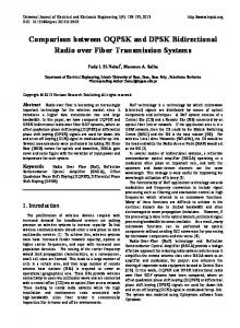
effective delay test pairs. We demonstrate that using Random (SIC or MIC) delay test pairs to test path delay faults produces higher delay fault coverage than that obtained with pseudo-random test pairs (produced from an LFSR). Next, we demonstrate that the same conclusion can be drawn when stuck-at or bridging fault coverage is targeted rather delay fault coverage. According to the above results, it would be very interesting to be able to materially generate RSIC or RMIC test sequences. This can be done from a structure described in [19]. It consists of a modified LFSR in which more than one shifting are used between two consecutive vectors. From a formal point of view, let us denote by σ the number of switchings between two consecutive vectors, and let T Q(t)=[Q1Q2…Qm] denote the column vector corresponding to the state of the LFSR at time t (m denotes the size of the LFSR). In a conventional LFSR with σ=1, the state at time t+1 is obtained by the matrix multiplication Q(t+1)=U.Q(t), where U is the companion matrix of the LFSR polynomial. With the modified LFSR proposed in [19], the state at time t+1 is obtained by Q(t+1)=Uσ.Q(t). Properties for the calculation of σ can be found in [19] and are not reproduced here for space consideration. An example of a modified LFSR providing truly random test patterns is shown in Figure 2 for a number of switchings σ=2.
+ 0
0
0
0
1
(a)
+ + 0
0
0
0
1
(b) Figure 2: (a) a classical primitive LFSR, (b) the corresponding modified LFSR
The example structure described in Figure 2 can be used to generate RMIC test sequences. The structure to generate RSIC test sequences is composed of the modified LFSR plus a mapping logic circuit allowing to produce single bit changes. This structure will be described in details in a future paper. This work comes into the general framework of testing sub-micron VLSI designs, which are more sensitive to delay defects and bridging faults. It also serves as a basis for another work on the generation of generic test sequences (Random SIC test sequences) that are able to reach a very high defect coverage in modern VLSI designs.
Acknowledgments The authors would like to thank René DAVID from the "Laboratoire d'Automatique de Grenoble" for his participation in this work.
References [1] M. Abramovici, M.A. Breuer and A.D. Friedman, “Digital Systems Testing and Testable Design”, Computer Science Press, 1990. [2] H.J. Wunderlich and Y. Zorian, “Built-In Self Test (BIST): Synthesis of Self-Testable Systems”, Kluwer Academic Publishers, 1997. [3] Y. Zorian, “Testing the Monster Chip”, IEEE Spectrum, Vol. 36, N° 7, pp. 54-60, 1999. [4] K. Furuta, S. Yamazaki and M. Sato, “Evaluations of Various TPG Circuits for Use in Two-pattern Testing ”, IEEE VLSI Test Symposium, pp. 242-247, 1994. [5] C. Chen and S. Gupta, “BIST Test Pattern Generators for Stuck-Open and Delay Testing”, IEEE Euro. Design & Test Conf., pp. 289-296, 1994. [6] D.K. Pradhan and M. Chatterjee, “GLFSR: A New Test Pattern Generator for Built-In Self Test”, IEEE Int. Test Conf., pp. 481-490, 1994. [7] S. Pilarski and A. Pierzynska, “BIST and Delay Fault Detection”, IEEE Int. Test Conf., pp. 236-241, 1993. [8] W. Wang and S.K. Gupta, “Weighted Random Robust Path Delay Testing of Synthesized Multilevel Circuits”, IEEE VLSI Test Symposium, pp. 291-297, 1994. [9] P. Girard, C. Landrault, V. Moreda and S. Pravossoudovitch, “An Optimized BIST Test Pattern Generator for Delay Testing”, IEEE VLSI Test Symposium, pp. 94-99, 1997. [10] G.L. Smith, “Model for Delay Faults Based upon Paths”, IEEE Int. Test Conf., pp. 342-349, 1985. [11] M. Sivaraman and A.J. Strojwas, “Diagnosis of Parametric Path Delay Faults”, IEEE Int. Conf. on VLSI Design, pp. 412417, 1996. [12] J.A. Abraham and H. Shih, “Testing of MOS VLSI Circuits”, IEEE Int. Symp. on Circuits and Systems, pp. 12971300, 1985. [13] S. Koeppe, “Modeling and Simulation of Delay Faults in CMOS Logic Circuits”, Proc. of Int. Test Conf., pp. 530536,1986. [14] TestGen, version Tg3.0.2 User Guide, Synopsys Inc., 1999. [15] F. Brglez, D. Bryant and K. Kozminski, “Combinational Profiles of Sequential Benchmark Circuits”, IEEE Int. Symp. on Circuits and Systems, pp. 1929-1934, 1989. [16] W.K. Lam, A. Saldanha, R.K. Brayton and A.L. Sangiovanni-Vicentelli, “ Delay Fault Coverage, Test Set Size, and Performance Trade-Offs”, IEEE Trans. on CAD, Vol. 14, N° 1, pp. 32-44, January 1995. [17] K.T. Cheng and H.C. Chen, “ Delay Testing for Non-Robust Untestable Circuits”, IEEE Int. Test Conf., pp. 954-961, 1993. [18] S. Crepaux-Motte, M. Jacomino and R. David, “An Algebraic Method for Delay Fault Testing”, IEEE VLSI Test Symposium, pp. 308-315, 1996. [19] R. David, “Random Testing of Digital Circuits: Theory and Applications”, Marcel Dekker, Inc., New York, 1998.