Comparison between various types of multiple optical tweezers J.-M. Fournier*a, F. Merendaa, J. Rohnera, P. Jacquotb, and R.P. Salathéa Advanced Photonics Laboratory, École Polytechnique Fédérale de Lausanne, STI, IMT, LOA, station 17, CH-1015, Lausanne, Switzerland; b Nanophotonics and Metrology Laboratory, EPFL, STI, IMT, CH-1015, Lausanne, Switzerland a
ABSTRACT Many types of optical tweezers arrays have been proposed and developed for use in conjunction with microfluidics for bio-chemical essays. Trap arrays rely on different methods allowing various degrees of flexibility and relative trapping efficiencies. Among the different techniques currently employed, it is not simple to distinguish which ones produce adequate performances for a given task in bio-chemistry. Experimental results for trapping efficiently diverse biological specimens allow distinguishing between the properties of optical trap arrays based on techniques as different as interferometry, holography, Fresnel or Fraunhoffer diffraction of diffractive structures, generalized phase contrast, microlens assemblies, micro-mirrors matrices, and also clusters of individual tweezers. The bulkiness of those systems is another important factor in the design of labs–on-a-chip; in particular the use of cumbersome microscope objectives can be detrimental to chip optimization. Arrangements of tweezers produced with different concepts should be compared in terms of efficiency, ease of use, and number of traps simultaneously exploitable Keywords: optical tweezers, microfluidics, diffractive optics, optical micromanipulation, optical forces, optical sorting, optical grip, Talbot imaging, Fresnel propagation, micro-mirrors, micro-lenses
1. INTRODUCTION This paper compares many types of multiple optical tweezers. These are made of ensembles of traps which can be arranged on periodic arrays or distributed among any kind of geometrical configuration, depending of the methods and apparatus employed to build them. This is not an exhaustive study of all types of multiple trapping, but many systems are listed and briefly described. Important properties are highlighted for a few devices, especially for systems associated with microfluidics. The aim is to review most multiple trapping possibilities to point out which ones are good candidates for building microfactories on microchips where trapping is a part of the process allowing biochemical analysis. Multiple tweezers built for cold atom manipulation are nevertheless considered, since they can provide insights for the development of massively parallel tweezers.
2. CONSIDERATIONS ON MULTIPLE TRAPS 2.1 The rise of multiple traps As soon as optical tweezers came into use within different communities, a need for multiple tweezers became clearly apparent. For the biology and biophysics worlds, proteins and filaments were first tethered to a base and attached at the other end to a sphere driven by a tweezers being used as a handle. But soon pairs of tweezers were needed to measure forces or more simply to pull, wind and unwind macromolecules [1, 2]. Such pairs of tweezers usually operate independently and are in common use today. An interference system designed to trap many particles was proposed to build space structures [3]; later on, interference patterns were used to generate arrays of traps [4, 5]. They soon found extensive use for making optical molasses and for building optical lattices, first filled with one or more cold atoms per site, [6-8] and later used for studying ultra-cold quantum gases [9, 10]. They also have been used for sorting particles by size or by refractive index [11]. *
[email protected] Optical Trapping and Optical Micromanipulation V, edited by Kishan Dholakia, Gabriel C. Spalding, Proc. of SPIE Vol. 7038, 70381G, (2008) · 0277-786X/08/$18 · doi: 10.1117/12.796518
Proc. of SPIE Vol. 7038 70381G-1 2008 SPIE Digital Library -- Subscriber Archive Copy
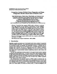
Many other phenomena and devices are now in use for producing multiple arrays of traps. Most of them are described in this paper. A need for very large arrays of traps is instigated by the development of micro-factories capable of simultaneously conducting various chemical and bio-physical essays on huge ensembles of biological samples. 2.2 Trapping in microfluidics Such micro-factories designed to perform biological analyses with very small volumes of reactants should be based on microfluidic chips to incorporate the means to convey the objects to the trapping areas and also to allow chemical substances and rinsing fluids to bath the trapped objects. In most occurrences, biological specimens should definitely stay surrounded by some liquids for at least two reasons: (i) to avoid any sticking to the walls of the chip, (ii) to avoid any effect associated with the contact to a surface or any other interaction effect (such as van der Waals forces) which could modify the physical and chemical properties of the understudied object. The presence of 3D traps in microfluidic channels allows fulfilling these two conditions and offers prospects for trapping, analyzing, and sorting. Most of the time, the chips are designed to work under an optical microscope, a widespread feature in biology. 2.3 Optical forces In the optical micromanipulation community, “radiation pressure” is often referred to as the main reason for displacing and holding particles. The term is rather vague and not always clearly defined. To unambiguously understand the action of electromagnetic (EM) waves on small objects, one should consider all the forces being exerted on such objects when they are subjected to such EM fields. These forces derive from momentum conservation and one usually considers only the static force, when the light field is oscillating with an extremely high frequency. Forces resulting from light waves are extensively used in atomic physics to slow down atoms and to confine them in localized areas. In those applications, the light field varies slowly over the extremely small dimension of the atoms, and the force can be expressed as a sum of two terms which have been identified as: x the scattering force, which pushes the object in the direction of the Poynting vector of the propagating wave, x the gradient force, relative to the gradient of intensity of the electromagnetic radiation: it can either attract the object towards the high intensity regions or repel it, depending on the object’s properties (size, , permittivity contrast with the background, etc). x A third type of force, named “optical binding”, becomes significant when multiple particles interact with each other. It is a consequence of the self-consistent interaction between the multiple particles and the incident wave[12].
Gradient
Scattering
Binding
Fig. 1. Optical forces (red arrows) exerted on particles located in a light beam with gaussian intensity distribution propagating from bottom to top (green arrows)
The scheme represented in Figure 1 shows in which directions these forces push spheres of refractive index higher than the one of their surrounding medium, e.g. spheres of polystyrene in water, when illuminated with a Gaussian intensity distribution. However, this partition of optical forces in three components applies effectively only in the case of particles much smaller than the wavelength of light; in this special case of Rayleigh scattering, an analytical expression is established for these forces. When dealing with micron size particles, the above approximation is not valid at all, and forces must be computed via a direct application of the Lorentz force or via the Maxwell stress tensor.
Proc. of SPIE Vol. 7038 70381G-2
3. MULTIPLE TRAPPING APPROACHES The generation of optical traps is directly associated with the creation of light intensity distributions presenting sharp spatial variations. Many schemes may lead to such optical landscapes, sometimes guided by competing optical devices capable of harnessing light for the production of arrays of traps. This chapter gives a brief description of the most currently used methods; the next one presents techniques recognized to cover large fields of view, including a more detailed analysis of three schemes developed and implemented in our group. Emphasis is put on trapping efficiency in laminar flows, on simplicity of use, and on overall robustness. Very efficient trapping can be achieved with evanescent waves; however, we just mention methods related to trapping with near-field forces here but do not elaborate on them since this paper concentrates more on 3D trapping 3.1 Arrays of tweezers made by self-trapping Some of the simplest devices generating arrays of traps rely on optical binding. Setups require either one single beam [13] or two counter propagating beams [14, 15] or more [16]. In the Mie scattering regime, binding can be simply viewed as the results of the modification of an optical landscape due to the presence of one or more particles in the field: they scatter light that interferes with the illumination carrier. Each particle present in the field modifies the overall intensity distribution, then affecting the forces exerted on all other particles. Self-consistency governs their final arrangement, which depends on many variables related to the beams (number, relative intensities, polarization) and to each individual particle present (position but also size, shape, permittivity) [17]. Optical binding is characterized by the simplicity of the optical setups necessary to observe the phenomenon, which contrasts with the extreme complexity in the interpretation of resulting arrangements.
3.2 Multiple tweezers made with independent lasers The surest way to avoid interactions between traps in an arrangement of tweezers is to use independent lasers. For example, an experiment of trapping in microfluidics to test cellular signaling reactions mediated by G protein coupled receptors relied on a set of 4 fiber lasers dedicated to trapping and 2 lasers to investigate fluorescence [13]. Several systems take advantage of vertical cavity surface emitting laser (VCSEL) arrays to generate multiple beams [18]. The simple control of spatial and temporal emission of the VCSELs confers very appreciable flexibility for micromanipulation with hardware compactness. Trapping forces can be applied continuously and independently to any area of the tweezers array [19].
3.3 Interferometric traps First proposed in the 70’s [3] and used to assist freezing of arrays of linear traps [4], interferometric traps have been pioneered in the late 80’s [5]. Optical setups created with cascades of beam splitters or simply by illuminating Diffractive Optical Elements (DOE) generated arrays of hundreds of traps and later on of thousands of traps [20, 21].
a)
b)
Fig. 2. a) Array of 3000 interferometric traps with a few 2 micron polystyrene spheres trapped at the top surface of a cell b) 5-fold symmetry interference pattern produced to trap polystyrene beads in order to form a quasi-crystal
Proc. of SPIE Vol. 7038 70381G-3
Most common geometries developed in interferometric trapping are parallel arrays of linear traps and matrices of traps distributed along a 3-fold or 5-fold symmetry [5]. Most of the time these systems are used to arrange particles confined in one plane, at distances and locations determined by the interference pattern (2D trapping). Nevertheless, more sophisticated setups succeed in trapping in 3D by compensating for scattering forces either with photorefractive crystals [22] or with other means using counterpropagating beams [21, 23]. Interferometric traps can also be produced with the help of a microscope objective to increase available NA and therefore to perform 3D trapping. [24]. The limited field of view of the microscope objective creates a serious limitation to the number of traps generated this way.
3.4 Fizeau-Tolansky traps Another class of interferometric traps rely on multiple beam interference producing so-called Fizeau or Tolansky fringes, which present very fine lines raising slopes with prominent gradients. When the dipolar approximation applies, as is the case for cold atoms and small Bose-Einstein condensates, such gradients potentially create traps with superior strength. This property has been taken advantage of in the early 1990s, to study, e.g., the influence on the trapping of rubidium atoms under far-off resonance conditions of an Airy function intensity profile inside a Fabry-Perot resonator in 1993 by Miller et al [25], and chaos in non-linear resonators with sodium atoms [26]. Trapping of atoms within Fabry-Perot resonators is still a popular topic [27]. Multi-pass interference has also been explored to trap mesoscopic particles. The picture of a gradient force to represent optical trapping falls off in the Mie regime, where rigorous calculations must be carried to figure out the trapping potential, which depends a lot on the size and permittivity of the objects to be trapped. Nevertheless, for appropriate combinations of trap size, bead size, and optical index contrast, remarkable enhancement of trapping strength has been measured in a study comparing the efficiency of arrays of sinusoidal traps versus arrays of Fizeau-Tolansky traps. The latter were produced with two close plates having high reflectivity surfaces, leading to varying configurations within the same interference field, including contrast inversion within the same field [21, 28, 29]. This shows that exalting the gradient in a field can also be beneficial in trapping in the Mie regime.
3.5 Trapping in Speckle light pattern Speckle pattern intensity distribution results from interference and always displays high contrast; it is intrinsically threedimensional and speckle grain sizes obey a well defined Poisson statistic. Due to the size difference between the length and the width of speckle “grains”, different cooling efficiency can be achieved along the elongated direction and along the short one. This has been verified by trapping cold cesium atoms [30-32]. Trapping in speckle pattern has been revived with Bose-Einstein Condensates (BEC) to modify the expansion of dilute condensates. The random potential of speckle fields can been switched on either adiabatically or abruptly after some initial expansion of a BEC to stop the expansion of the atomic cloud, thanks to trapping in the deepest wells of the potentials. [33]. The suppression of the 1D expansion of an interacting elongated Bose-Einstein condensate in a random potential is observed and measured by shining a speckle pattern from a blue detuned laser onto the atoms of a condensate at equilibrium to release the axial confinement [34]. The experimental study of the transport of coherent interacting matter-waves in a 1D random potential induced by laser speckle recently led to the direct observation of Anderson localization of a controlled matter wave with a very diluted Bose-Einstein condensate in expansion in an optical guide where some disorder is applied through a speckle template having a very small grain size (less than one micron): the small induced disorder is capable of stopping the propagation of the condensate [35, 36].
3.6 Holographic traps Diffractive elements –on axis and holographic off-axis– have been used to simplify the use and the setting up of interferometric tweezers [20, 37]. Later, as proposed by Chiou [24], the field distribution produced by such diffractive
Proc. of SPIE Vol. 7038 70381G-4
elements has been imaged under a microscope [38]. This increases considerably the Numerical Aperture (NA) of the optical system, leading to 3D trapping, but at the price of a large reduction of the field of view, then reducing significantly the resulting number of traps available simultaneously. The first works using diffractive optics for manipulation of small particles concentrated for obvious reasons on on-axis optics. However, Computer Generated Holograms (CGH) became very popular in optical trapping [39].
3.7 Multiple tweezers produced with SLMs Spatial light modulators (SLM) such as Digital Micro Devices (DMD) and Liquid crystal SLM are very appealing systems for the manipulation of a light field. Amplitude modulators such as DMDs are regarded as potentially efficient devices to reconfigure light intensity distributions [40, 41]. They have also been used to demonstrate particle manipulation with a non-coherent light source [42, 43] and to trap with femto-second pulses [44]. Later, accessory light modulator packages (ALP) added the flexibility of digital control of DMDs to produce and manipulate optical trap lattices, e.g. ruling the trap profile, array dimension, hopping over the trap lattice, and steering [45]. A new generation of scanning DMDs is equipped with servo control, and allows the micro-mirror tilt angle to be a function of the input command signal (former generations were binary: the micro-mirrors could only take two positions). Experiments with a two axis tilt mirror SMMA created clusters of laser micro-beams arrays. Added to a choice of proper reflecting surfaces, this led to controlling the impact angle of the individual laser beams with independent directional control applied over micro/nano-particles, thus generating an optical beam gripper effect [46]. Major improvements on dynamic multiple traps resulted from the introduction of rewritable phase modulators based on liquid crystals to modulate light distributions and generate dynamic multiple optical tweezers by continuously rewriting the SLMs [47, 48]. This provides a non-mechanical approach to steering and modifying beams. At the same time, it intrinsically extends the potentials of multiple tweezers by rearranging the geometry of the arrays. However this comes with some lowering in diffraction efficiency and with some decrease in stability. Indeed, when generating large arrays of traps with SLM’s, aliasing may occur because of their limited resolution, typically causing low diffraction efficiency and unwanted diffraction orders. Moreover, the homogeneity of the trapping forces achievable for off–axis positions or when generating arrays of traps is clearly an issue [49, 50]. It can be asserted that diffraction efficiency in a CGH-based system imprinted on a SLM greatly depends on spatial trap locations, array geometry and symmetry and is compromised by the limited space-bandwidth product of the SLM and by the unwanted zero-order and higher-orders accompanying any desired diffraction pattern.
3.8 Magnetic tweezers Magnetic tweezers present several advantages over optical tweezers for single molecule micromanipulation. They are helpful in measuring small forces, in the piconewton range, in leaving cell processes, using magnetic particles and magnetic field gradients. Magnetic twisting has been extensively utilized to study biological materials, to twist, wind and unwind proteins, and to measure viscoelastic properties of living cells, in particular with multi-pole magnetic tweezers enabling maneuvering small magnetic probes inside living cells. We simply mention here a review article on those systems, which are not treated here since they are not based on optical forces and, moreover because they don’t seem to be candidates for multiple tweezing [51].
3.9 Fiber traps Trapping with optical fibers was first demonstrated in the group of M. Prentiss. [52]. Similar systems using 2 counter propagating monomode fibers have been demonstrated to be capable of trapping and also of stretching biological samples [53]. In principle, those devices can easily be parallelized without major difficulties: it suffices to assemble arrays of pairs of fibers to generate an assemblage of traps. Likewise, it seems that parallelization could apply to methods recently developed for 3D trapping with a single fiber, e.g., through highly tapered fibers [54], or, with a technique with annular core fibers having their end-face cut in order to reflect towards a focal area the light having propagated through the core [55].
Proc. of SPIE Vol. 7038 70381G-5
Optical imaging fiber bundles with high NA allow for generating and regenerating arrays of traps by coupling a laser beam into the proximal end of the bundle, distributing light among the fibers. Each illuminated individual fiber in the array propagates light to the distal face of the bundle, where focusing elements at the end of each fiber concentrate the light to form optical traps. [56]. Such imaging fiber arrays offer promising possibilities relative to the number of traps to be addressed in parallel, since dense arrays of about (~5x10⁴ traps/mm2) tweezers can be achieved. [57]. The same group at Tufts University has demonstrated the capability of capturing and arraying microspheres in parallel by integrating a digital micromirror device to generate patterns of optical traps at the entrance of a fiber bundle. This process should enable individual control of each trap (for size, position, and shape) in the array.
3.10 Evanescent wave trapping and plasmon trapping Very efficient guiding and trapping can be achieved by involving near field optics, thanks to the contribution of evanescent waves and of plasmons. A first demonstration of particles guiding along optical guides was made in 1992. [58, 59]. Many groups have studied the organization of particles in various configurations using near field trapping and/or binding [16, 60-64]. Without denying the interest of those methods, and particularly the possibility of trapping over large fields of view, we do not elaborate on them since this paper concentrates more on 3D trapping.
3.11 Angular momentum, angular vortices A family of optical tweezers uses Laguerre–Gaussian beams, in other words TEM*01 modes, to transfer orbital angular momentum of the optical vortex beam to particles trapped in zero intensity area, as has been demonstrated in 1995 by He et al. [65].This provides an additional dimension of rotation to optical trapping. Most work performed in trapping and sorting with Gaussian beams has been an inspiration for using LG beams and many of the experiments described here have also been more or less repeated with LG beams. Several reviews on optical trapping describe works with LG beams [66, 67].
3.12 Time multiplexing Independent manipulation of several particles, such as alignment and positioning on a predetermined line shape has been pioneered by Misawa, through traps built with a time-shared beam. The position of latex structures created by sequences of manipulation/polymerization was then controlled by laser beams [68, 69]. This interesting approach stays limited in the number of sites which can trap together. On a more recent time-sharing example, 24 time-multiplexed helical zone plates are used to generate Laguerre-Gaussian laser modes. They are produced on a ferroelectric liquid crystal SLM which allows for the independent control of traps resulting from these special Fresnel zone plates. The ferroelectric mechanism offers high speed switching, providing fast modification and smooth movement of the traps. This particular system has been applied to trap and maneuver yeast cells and fungal spores [70]. Another powerful way to take advantage of time sharing consists in scanning an array of traps all at once. Such experiments have been performed in a counter-propagating beam setup with Acousto-Optics Devices (AOD). Since AODs can scan at hundreds of kHz, large arrays of hundreds of optical traps have been created this way. This is a very fast way to create and dynamically change two independent 2D arrays of optical tweezers [71]. It has been used to manipulate titanium dioxide particles by simultaneously scanning a pattern and its mirror image at 4.5 kHz with acoustooptic modulators. This is performed by changing position in 34 steps over a total period of 1.2s, yielding an average speed of the particles of 20 ȝm/s. 3D arrays of traps have been generated by fast switching between two beam paths using AODs, a Pockels cell, and polarizing beam splitters [72].
Proc. of SPIE Vol. 7038 70381G-6
4. 3D MULTIPLE TRAPPING OVER VERY LARGE FIELDS OF VIEW 4.1 From trapping with an optical microscope to microscope-less trapping The efficiency of interferometric tweezers has been demonstrated for massively parallel 2D trapping as illustrated in paragraph 3.3 with the simultaneous trapping of 20,000 polystyrene spheres [21] and as described in paragraphs 3.4. This approach doesn’t require any optics around the trapping area, then leaving a lot of available space around it. On the other hand, it is essential to keep biological specimens away from any surface for proper bio-chemical analysis. Therefore, there is an essential need for 3D trapping, to hold any particle away from touching any wall or any face of the microfluidic cells. This chapter presents several methods allowing hundred or thousands of 3D traps to work in parallel. In most optical tweezers, a microscope objective is used to trap and also to collect optical signatures such as fluorescence. Both functionalities require very high numerical aperture. This imposes the use of very bulky objectives, most of the time designed for water immersion or for oil immersion. Those leave no working space around the trapping area, and forbid the whole miniaturization of the system. Thus, it is tempting to bare immersion microscope objective from microdevices. Eventually, long working distance microscope objective with relatively low magnification can be tolerated, e.g., to be used for observation.
4.2 Generalized Phase Contrast Method A particularly efficient technique is the Generalized Phase Contrast (GPC) method invented in the mid 90’s and patented by the Technical University of Denmark (see www.ppo.dk). Based on the combination of a programmable SLM device and an advanced graphical user-interface, the GPC method enables real-time, interactive and arbitrary control over the dynamics and geometry of synthesized light patterns. The versatility of the GPC approach is reflected by the fact that a user can independently specify the number, the size, the shape, the intensity, the spatial position and the speed of each beam by using a mouse attached to a computer. Recent experiments have shown that GPC-driven micromanipulation provides a platform for user-guided assembly of a plurality of particles in a plane, control of particle stacking along the beam axis, manipulation of multiple hollow beads, the organization of living cells into three-dimensional colloidal structures and real-time manipulation of synthesized micro-structures with nano-tools. GPC can reconstruct fully dynamic arbitrary arrays with almost 90% efficiency requiring no computational overhead, which is compulsory in a diffractive optics based approach like CGH. Moreover, trap resolution may be set equal to SLM resolution. The lateral intensity distribution that forms the trapping patterns can easily stretch along the extent of the whole microscopic field of view. Real-time user-interactive manipulation of large particle arrays (hundreds of particles) has been demonstrated with this method.
4.3 Arrays of microlenses When aiming at massively parallel trapping, a high trapping efficiency is necessary for fully taking advantage of the total laser power available, which is shared among all the traps, and for minimizing as much as possible the intensity in the traps, then reducing the risk of photodamage to trapped biological particles. Also, trapping should be as equally reliable all over the array to ensure ensemble stability in microfluidic flows. Although arrays of up to 400 optical tweezers have been demonstrated both with spatial light modulators (SLMs) [47] and laser scanning [71], these methods have not yet been applied to optical trapping of multiple biological particles in microfluidic flows, which might reflect some of their drawbacks. As indicated earlier, limited resolution, inhomogeneities, and low diffraction efficiencies are often associated with HOTs made with liquid crystal SLMs. On the other hand, when generating large arrays of traps with laser scanning techniques, very high peak irradiances are reached that may further enhance the risk of damage to biological particles through two-photon processes. A technique for forming extended arrays of optical tweezers developed in our group takes advantage of refractive microlens arrays [73, 74]. While microlenses have been previously proposed for generating multiple optical traps, the employed arrangements were either limited to only four 3D traps [75] or to arrays of two-dimensional traps [76]. As we have demonstrated, by the appropriate choice of microlens arrays and by respecting specific optical conditions, arrays of microlenses can be successfully employed for generating hundreds of highly efficient 3D traps through high-NA objectives. Figure 3(a) shows an array of over 200 particles trapped simultaneously in three-dimensions. Such extended
Proc. of SPIE Vol. 7038 70381G-7
arrays are generated through lower magnification objectives (such as the Zeiss C-Apochromat 40x/1.2W in use here), offering the largest possible field of view. Moreover, the high power throughput of the system and the homogeneous quality of the microlens arrays ensures that each trap in the array is capable of holding objects at fluid flows exceeding 100 micrometers per second, thus enabling realistic processing speeds in microfluidic environments.
Fig. 3. Multiple optical trapping in microfluidic environments: (a) Array of 200 polystyrene beads, 2Pm in diameter, trapped using microlens arrays (b) Placing an array of optical tweezers within a micro-channel; (c) Manipulating arrays of trapped particles among different fluids flowing in a microfluidic device.
As illustrated in Figure 3b), the array of optical tweezers can be placed within the channels of a microfluidic device, simply by positioning the latter on top of the microscope objective. As further illustrated in Fig.3(c), the array of optical tweezers can be translated within the fluidic device, thus permitting the manipulation of an ensemble of particles across different reagents flowing within the microfluidic device.
4.4 Opto-Electronic Tweezers (OET) using light induced dielectrotrophoresis First described by Pohl in 1951, dielectrophoresis (DEP) exerts a force on any polarizable and electrically neutral particle bathed in a non-uniform electric field; this force results from the interaction of the dipole set up within the particle and the field which creates it. It can be exploited for cell trapping, steering, and analysis [77]. The electrical field gradients necessary to create such force can be generated not only by micro-electrodes but also by “virtual electrodes” created when illuminating a thin film of photoconductor, then leading to “Light induced Dielectrophoresis” (LIDEP). Modifying the light pattern changes the DEP force, and this can be made continuously, with non-coherent light [42, 43]. LIDEP requires much less optical intensity to trap than conventional optical tweezers. As a consequence, it has been shown that 15,000 traps can be produced with just 1mW of light and that trap stiffness per mW is increased almost 500 fold compared to conventional optical traps, with no loss of resolution [78]. Assemblies of traps made with LIDEP are called Opto-Electronic Tweezers (OET). They are particularly adapted to work with cells; however, they are not particularly efficient when spot size decreases under 5 microns. Smaller spots can only be generated with severe reduction of the trapping strength. In addition to opening up the possibility of using incoherent light sources, and of allowing trapping at microwatt powers, OET offer an alternative for direct optical imaging to pattern the traps.
4.5 Micromirrors arrays Recently, our group developed an approach for trapping based on high-NA parabolic micromirrors [74, 79], that allows the optics necessary for 3D optical trapping to be miniaturized and thus integrated at the level of a microfluidic chip. The distinctive characteristic of such micromirrors lies in the easily achieved high-NA coupled with achromaticity, a combination that can not be realized with other types of micro-optical components such as refractive or diffractive microlenses. Like other types of micro-optical elements, micromirrors are easily built in extended arrays with each micromirror forming its own optical tweezers, hence providing a natural approach to multiple optical trapping.
Proc. of SPIE Vol. 7038 70381G-8
Fig. 4. Multiple trapping with high-NA micromirror arrays. (a) Photograph of a microfluidic chip with integrated micromirrors and fluidic connections (b) Reflection bright field images of the micromirror array. In the present case, micromirrors with a pitch of 250Pm were employed (c) Collecting fluorescence light emitted by optically trapped 6Pm polystyrene beads with the high-NA achromatic micromirrors.
Figure 4 (a) shows a photograph of a microfluidic device with integrated micromirrors. The chip is a sandwich structure fabricated with two 1mm thick glass slides separated by a 100Pm spacer hosting the fluidic channels. The micromirror array, fabricated by molding of a microlens array, is integral with the lower glass slide. Fig. 4 (b) shows two magnified views of the micromirror array. The upper glass slide has holes and connectors for the fluidic circuitry. Forming multiple traps in the fluidic channel is simply achieved by shining a collimated laser beam onto the micromirror array. A key advantage of micromirrors for multiple trapping lies in that the trapping area is not restricted by the field of view of a microscope objective. As a consequence, the total number of traps may be increased at will. This advantage becomes essential when trapping larger particles like mammalian cells, having typical diameters in the 10-15ȝm range, as no more than 20-30 cells of such size could reasonably be trapped simultaneously in the field of view of a high-NA microscope objective. Furthermore, a microscope objective is not even necessary for observation when operating with micromirrors. Indeed, fluorescent light from the trapped particles is collected at high NA (hence with high efficiency) by the micromirrors themselves. Simple and inexpensive low-NA optics is then sufficient for relaying light signatures from all the traps simultaneously on a detector array, such as a CCD, as illustrated in Fig.4 (c) showing the micromirrors turning on as fluorescent polystyrene beads are trapped in the array. Thanks to the mirror’s achromaticity and the use of broadband reflection coatings, simultaneous operation with several arbitrary wavelengths (e.g. for fluorescence excitation and detection) is possible.
4.6 Talbot-Lohmann light shaping Sending an EM wave onto a 1D or 2D periodic structure generates periodicity along the wave propagating after it. This effect is related to constructive and destructive interference along the propagating field. It structures light to form socalled “Talbot self-images”. The term “image” is not fully appropriate, in the optical sense, since such images present an intensity distribution which “looks like” that of the original pattern but which indeed differs from one image to the next. For example, in the case of a checker board, the self-images resemble the original checkerboard but don’t have a uniform and equal intensity on all “white” pixels over the whole area. In the amplitude case, a Ronchi Ruling illuminated with a plane wave reproduces a light pattern similar to the ruling at every “Talbot distance” zT, with zT = 2nd2/Ȝ, d being the pitch of the ruling, n an integer, and Ȝ the wavelength of light. In between those planes at any half-Talbot distance
Proc. of SPIE Vol. 7038 70381G-9
zT/2 = (2n+1)d2/Ȝ the same light pattern appears, but with contrast inversion. To avoid energy losses, it is common to consider phase structures. Illuminated by a plane wave, they diffract patterns which present planes with intensity distributions appearing like the ones that an amplitude mask would produce, but with much less energy losses. In such a case, one should speak about “Talbot-Lohmann” images, since this line of work has been revived in the late 80’s by J. Thomas and A. Lohmann. [80]. Optical trapping in Talbot lattices was experimented with microspheres by Fournier et al. in the 90’s and also used as a tool for selective atom cooling [20] [81]. Later, Walker et al. carried out several experiments with cold atoms in Talbot structures [82]. Our group applied the effect to establish 3D trapping of polystyrene microbeads [13, 21]. In this work, “cages of light” generated by the Talbot-Lohmann effect were generated by a phase diffractive plate simply illuminated with a large Gaussian beam propagating along the z-direction, perpendicular to the plate. The utilized light cages were delimited in the z-axis by two successive half-Talbot planes, and in the x.y axes by the checker board pattern used for the original phase template. The Talbot effect was further mentioned as a based for optical trapping due to periodicity of an optical lattice formed by the interference of multiple plane waves generated by a spatial light modulator. [83]. Talbot images have also been recently used to sort polystyrene particles in microfluidics with two-dimensional traps [84]. 3D Talbot-Lohmann trapping has clearly been observed with microlens arrays [74]. A very interesting approach consist in using fractional Talbot images generated by a checker-board like phase plate with binary phase steps. At fractional imaging distances defined by z = N• ZT + (P/Q)ZT very interesting light distributions appear, depending on the grating period and on the width and height of the phase step. In the 1D case, the Ronchi etched element generates square shaped output patterns such that a checker board arrangement appears, with compression factors of 1:4 and even 1:9 compared to the original template. [85] We have simulated many kinds of templates to produce noteworthy Talbot-Lohmann structures capable of generating high gradients not only in the x,y directions, but also in the z directions. Then we produced phase plates which diffract accordingly to the simulation, generating new arrays of traps. In the latter, square traps have x and y dimensions 4 times smaller than the original checkerboard unit, then carrying 16 times more intensity than what is sent to one unit on the diffractive checker board. This restructuring of light in the Fresnel diffraction regime allows the production of huge arrays of 3D traps which are simple to use (one simply needs to illuminate them with a “wide” laser beam) and easy to fabricate. Indeed, if one desires a trapping structure of a given size, it suffices to etch a glass plate with units 4 times wider than the desired structure. Such diffractive Talbot-Lohmann restructuring of light generates 3D arrays of 3D traps. Those have been fabricated and tested successfully to trap different sizes of polystyrene spheres in the 2-5 micron range [21].
(b)
(a)
Fig. 4. Trapping in Fresnel diffraction structures : (a) setup – a collimated wave illuminates the diffractive structure placed at the bottom of a microfluidic chip (b) Talbot-Lohmann sub-images as they appear along the vertical direction above the diffractive plate.
Proc. of SPIE Vol. 7038 70381G-10
A simple use of these structures would be to insert them at the bottom of a microfluidic chip where they can be embedded in a high index resin to control the required phase step. With a proper design of the phase plate, one can locate only one chosen plane of Talbot-Lohmann images into the microfluidic channels. It suffices to illuminate the chip with a collimated beam, normally to its surface, to generate the trap array. The available number of traps is only limited by the size of the diffractive plate and by the available laser power. This system could also work with incoherent light, since the self-imaging effect works quite well in white light for the first Talbot planes (it is then known as the Laue effect).
5. CONCLUSION Many approaches lead to multiple optical trapping, each of them with pros and cons regarding targeted bio-chemical applications. It seems clear that the techniques most popular today in optical trapping are not appropriate for future massively parallel arrays of tweezers mounted on microchips. Several designs are currently explored to allow 3D trapping of hundreds and even thousands of objects over very large field of views. The choice of a system can be made among many different methods, depending on the priority given to properties such as interactivity, real-time control of the geometry and of the dynamic of traps, control over the shape, the spatial position and the number of traps. 3D colloidal studies can also benefit from the flexibility related to some methods to trap simultaneously considerable numbers of particles.
REFERENCES [1] [2] [3] [4] [5] [6] [7] [8] [9] [10] [11] [12] [13] [14]
Visscher, K., Gross, S. P., and Block, S. M., “Construction of multiple-beam optical traps with nanometerresolution position sensing,” IEEE Journal of Selected Topics in Quantum Electronics, 2(4), 1066-1076 (1996). Strick, T. R., Allemand, J. F., Bensimon, D., Bensimon, A., and Croquette, V., “The elasticity of a single supercoiled DNA molecule,” Science, 271(5257), 1835-1837 (1996). Labeyrie, A., “Standing Wave and Pellicle - Possible Approach to Very Large Space Telescopes,” Astronomy and Astrophysics, 77(1-2), L1-L2 (1979). Chowdhury, A., Ackerson, B. J., and Clark, N. A., “Laser-Induced Freezing,” Physical Review Letters, 55(8), 833-836 (1985). Burns, M. M., Fournier, J. M., and Golovchenko, J. A., “Optical Matter - Crystallization and Binding in Intense Optical-Fields,” Science, 249(4970), 749-754 (1990). Verkerk, P., Lounis, B., Salomon, C., Cohentannoudji, C., Courtois, J. Y., and Grynberg, G., “Dynamics and Spatial Order of Cold Cesium Atoms in a Periodic Optical-Potential,” Physical Review Letters, 68(26), 38613864 (1992). Grynberg, G., Lounis, B., Verkerk, P., Courtois, J. Y., and Salomon, C., “Quantized Motion of Cold Cesium Atoms in 2-Dimensional and 3-Dimensional Optical Potentials,” Physical Review Letters, 70(15), 2249-2252 (1993). Hemmerich, A., and Hansch, T. W., “2-Dimensional Atomic Crystal Bound by Light,” Physical Review Letters, 70(4), 410-413 (1993). Rom, T., Best, T., van Oosten, D., Schneider, U., Folling, S., Paredes, B., and Bloch, I., “Free fermion antibunching in a degenerate atomic Fermi gas released from an optical lattice,” Nature, 444(7120), 733-736 (2006). Lewenstein, M., “Atomic physics - The social life of atoms,” Nature, 445(7126), 372-+ (2007). MacDonald, M. P., Spalding, G. C., and Dholakia, K., “Microfluidic sorting in an optical lattice,” Nature, 426(6965), 421-424 (2003). Thirunamachandran, T., “Intermolecular Interactions in the Presence of an Intense Radiation-Field,” Molecular Physics, 40(2), 393-399 (1980). Fournier, J. M., Rohner, J., Jacquot, P., Johann, R., Mias, S., and Salathé, R. P., "Assembling mesoscopic particles by various optical schemes." Proc SPIE 5930, 1-10 (2005) Tatarkova, S. A., Carruthers, A. E., and Dholakia, K., “One-dimensional optically bound arrays of microscopic particles,” Physical Review Letters, 89(28), - (2002).
Proc. of SPIE Vol. 7038 70381G-11
[15] [16] [17] [18] [19] [20] [21] [22] [23] [24] [25] [26] [27] [28] [29] [30] [31] [32] [33] [34] [35] [36] [37] [38]
Singer, W., Frick, M., Bernet, S., and Ritsch-Marte, M., “Self-organized array of regularly spaced microbeads in a fiber-optical trap,” Journal of the Optical Society of America B-Optical Physics, 20(7), 1568-1574 (2003). Andrews, D. L., and Rodríguez, J., “Collapse of optical binding under secondary irradiation,” Optics Letters, 33, 1830-1832 (2008). Maystre, D., and Vincent, P., “Making photonic crystals using trapping and binding optical forces on particles,” Journal of Optics a-Pure and Applied Optics, 8(12), 1059-1066 (2006). Ogura, Y., Kagawa, K., and Tanida, J., “Optical manipulation of microscopic objects by means of verticalcavity surface-emitting laser array sources,” Applied Optics, 40(30), 5430-5435 (2001). Flynn, R. A., Birkbeck, A. L., Gross, M., Ozkan, M., Shao, B., Wang, M. M., and Esener, S. C., “Parallel transport of biological cells using individually addressable VCSEL arrays as optical tweezers,” Sensors and Actuators B-Chemical, 87(2), 239-243 (2002). Fournier, J. M., Burns, M. M., and Golovchenko, J. A., "Writing Diffractive Structures by Optical Trapping," Proc SPIE 2406, 101-111 (1995) Rohner, J., "Light structuring for massively parallel optical trapping," PhD dissertation, Ecole Polytechnique Fédérale de Lausanne, Lausanne (2007). Wang, W., Chiou, A. E., Sonek, G. J., and Berns, M. W., “Self-aligned dual-beam optical laser trap using photorefractive phase conjugation,” Journal of the Optical Society of America B-Optical Physics, 14(4), 697704 (1997). Casaburi, A., Pesce, G., Zemanek, P., and Sasso, A., “Two- and three-beam interferometric optical tweezers,” Optics Communications, 251(4-6), 393-404 (2005). Chiou, A. E., Wang, W., Sonek, G. J., Hong, J., and Berns, M. W., “Interferometric optical tweezers,” Optics Communications, 133(1-6), 7-10 (1997). Miller, J. D., Cline, R. A., and Heinzen, D. J., “Far-Off-Resonance Optical Trapping of Atoms,” Physical Review A, 47(6), R4567-R4570 (1993). Moller, M., and Lange, W., “Radiation Trapping - an Alternative Mechanism for Chaos in a Nonlinear-Optical Resonator,” Physical Review A, 49(5), 4161-4169 (1994). Lee, S. K., Lee, H. S., Kim, J. M., and Cho, D., “Optical dipole trap using a Fabry-Perot interferometer as a power buildup cavity,” Journal of Physics B-Atomic Molecular and Optical Physics, 38(8), 1381-1389 (2005). Tolansky, S., [Multiple Beam Interferometry of Surfaces and films] Clarendon Press, (1948). Rohner, J., Fournier, J. M., Jacquot, P., Merenda, F., and Salathé, R. P., "Multiple optical trapping in high gradient interference fringes," Proc SPIE 6326, U52-U61 (2006) Boiron, D., Michaud, A., Fournier, J. M., Simard, L., Grynberg, G., and Salomon, C., "Strong confinement of cesium atoms in far detuned dipole traps, lattices, and speckle patterns," Proc. of CLEO/Europe-EQEC’98. Boiron, D., Mennerat-Robilliard, C., Fournier, J. M., Guidoni, L., Salomon, C., and Grynberg, G., “Trapping and cooling cesium atoms in a speckle field,” European Physical Journal D, 7(3), 373-377 (1999). Boiron, D., Michaud, A., Fournier, J. M., Simard, L., Sprenger, M., Grynberg, G., and Salomon, C., “Cold and dense cesium clouds in far-detuned dipole traps,” Physical Review A, 57(6), R4106-R4109 (1998). Fort, C., Fallani, L., Guarrera, V., Lye, J. E., Modugno, M., Wiersma, D. S., and Inguscio, M., “Effect of optical disorder and single defects on the expansion of a Bose-Einstein condensate in a one-dimensional waveguide,” Physical Review Letters, 95(17), 170410 (2005). Clement, D., Varon, A. F., Hugbart, M., Retter, J. A., Bouyer, P., Sanchez-Palencia, L., Gangardt, D. M., Shlyapnikov, G. V., and Aspect, A., “Suppression of transport of an interacting elongated Bose-Einstein condensate in a random potential,” Physical Review Letters, 95(17), 170409 (2005). Sanchez-Palencia, L., Clement, D., Lugan, P., Bouyer, P., Shlyapnikov, G. V., and Aspect, A., “Anderson localization of expanding Bose-Einstein condensates in random potentials,” Physical Review Letters, 98(21), 210401 (2007). Billy, J., Josse, V., Zuo, Z. C., Bernard, A., Hambrecht, B., Lugan, P., Clement, D., Sanchez-Palencia, L., Bouyer, P., and Aspect, A., “Direct observation of Anderson localization of matter waves in a controlled disorder,” Nature, 453(7197), 891-894 (2008). Friedman, N., Kaplan, A., and Davidson, N., “Dark optical traps for ultra-cold atoms,” Advances in Atomic, Molecular and Optical Physics, 48, 99-151 (2002). Dufresne, E. R., and Grier, D. G., “Optical tweezer arrays and optical substrates created with diffractive optics,” Review of Scientific Instruments, 69(5), 1974-1977 (1998).
Proc. of SPIE Vol. 7038 70381G-12
[39] [40] [41] [42] [43] [44] [45] [46] [47] [48] [49] [50] [51] [52] [53] [54] [55] [56] [57] [58] [59] [60] [61] [62] [63]
Dufresne, E. R., Spalding, G. C., Dearing, M. T., Sheets, S. A., and Grier, D. G., “Computer-generated holographic optical tweezer arrays,” Review of Scientific Instruments, 72(3), 1810-1816 (2001). Jeremy, R., “Optical Tweezers Using the Texas Instruments’Digital Micromirror Device,” M.S. Dissertation, MIT, (2001). Tam, J. M., Biran, I., and Walt, D. R., “Parallel microparticle manipulation using an imaging fiber-bundle-based optical tweezer array and a digital micromirror device,” Applied Physics Letters, 89(19), - (2006). Chiou, P. Y., Chiang, Z., and Wu, M. C., “A Novel Optoelectronic Tweezer Using Light Induced Dielectrophoresis,” Proceedings of OMEMS 2003, 8-9 (2003). Chiou, P. Y., Ohta, A. T., and Wu, M. C., “Massively parallel manipulation of single cells and microparticles using optical images,” Nature, 436(7049), 370-372 (2005). Jiang, Y. Q., Matsumoto, Y., Hosokawa, Y., Masuhara, H., and Oh, I., “Trapping and manipulation of a single micro-object in solution with femtosecond laser-induced mechanical force,” Applied Physics Letters, 90(6), (2007). Lee, S. R., Kim, J. K., Won, Y. J., and Oh, K., “Generation of optical lattice and trapping particle using DMDALP,” Proc SPIE 6351, 63512A-9 (2006). Dagalakis, N. G., LeBrun, T., and Lippiatt, J., “Micro-Mirror Array Control of Optical Tweezer Trapping Beams ” Second IEEE Conference on Nanotechnology, Washington DC, August 26-28, 2002 Curtis, J. E., Koss, B. A., and Grier, D. G., “Dynamic holographic optical tweezers,” Optics Communications, 207(1-6), 169-175 (2002). Jesacher, A., Furhapter, S., Bernet, S., and Ritsch-Marte, M., “Diffractive optical tweezers in the Fresnel regime,” Optics Express, 12(10), 2243-2250 (2004). Sinclair, G., Jordan, P., Leach, J., Padgett, M. J., and Cooper, J., “Defining the trapping limits of holographical optical tweezers,” Journal of Modern Optics, 51(3), 409-414 (2004). Curtis, J. E., Schmitz, C. H. J., and Spatz, J. P., “Symmetry dependence of holograms for optical trapping,” Optics Letters, 30(16), 2086-2088 (2005). Gosse, C., and Croquette, V., “Magnetic tweezers: Micromanipulation and force measurement at the molecular level,” Biophysical Journal, 82(6), 3314-3329 (2002). Constable, A., Kim, J., Mervis, J., Zarinetchi, F., and Prentiss, M., “Demonstration of a Fiberoptic Light-Force Trap,” Optics Letters, 18(21), 1867-1869 (1993). Singer, W., Frick, M., Haller, T., Dietl, P., Bemet, S., and Ritsch-Marte, M., “Combined optical tweezers and optical stretcher in microscopy,” SPIE 4434, 227-232 (2001). Liu, Z. H., Guo, C. K., Yang, J., and Yuan, L. B., “Tapered fiber optical tweezers for microscopic particle trapping: fabrication and application,” Optics Express, 14(25), 12510-12516 (2006). Liberale, C., Minzioni, P., Bragheri, F., De Angelis, F., Di Fabrizio, E., and Cristiani, I., “Miniaturized all-fibre probe for three-dimensional optical trapping and manipulation,” Nature Photonics, 1(12), 723-727 (2007). Tam, J. M., Song, L. N., and Walt, D. R., “Fabrication and optical characterization of imaging fiber-based nanoarrays,” Talanta, 67(3), 498-502 (2005). Tam, J. M., Biran, I., and Walt, D. R., “An imaging fiber-based optical tweezer array for microparticle array assembly,” Applied Physics Letters, 84(21), 4289-4291 (2004). Gaugiran, S., Getin, S., Fedeli, J. M., Colas, G., Fuchs, A., Chatelain, F., and Derouard, J., “Optical manipulation of microparticles and cells on silicon nitride waveguides,” Optics Express, 13(18), 6956-6963 (2005). Kawata, S., and Sugiura, T., “Movement of Micrometer-Sized Particles in the Evanescent Field of a LaserBeam,” Optics Letters, 17(11), 772-774 (1992). Mellor, C. D., Bain, C. D., and Lekner, J., “Pattern formation in evanescent wave optical traps,” Proc. SPIE 5930, 352–361 (2005). Siler, M., Sery, M., Cizmar, T., and Zemanek, P., “Submicron particle localization using evanescent field,” Proc SPIE 5930, 0R1-0R9 (2005). Mellor, C. D., Sharp, M. A., Bain, C. D., and Ward, A. D., “Probing interactions between colloidal particles with oscillating optical tweezers,” Journal of Applied Physics, 97(10), 1-4 (2005). Garces-Chavez, V., Quidant, R., Reece, P. J., Badenes, G., Torner, L., and Dholakia, K., “Extended organization of colloidal microparticles by surface plasmon polariton excitation,” Physical Review B, 73(8), (2006).
Proc. of SPIE Vol. 7038 70381G-13
[64] [65] [66] [67] [68] [69] [70] [71] [72] [73] [74] [75] [76] [77] [78] [79] [80] [81] [82] [83] [84] [85]
Rockstuhl, C., and Herzig, H. P., “Wavelength-dependent optical force on elliptical silver cylinders at plasmon resonance,” Optics Letters, 29(18), 2181-2183 (2004). He, H., Friese, M. E. J., Heckenberg, N. R., and Rubinszteindunlop, H., “Direct Observation of Transfer of Angular-Momentum to Absorptive Particles from a Laser-Beam with a Phase Singularity,” Physical Review Letters, 75(5), 826-829 (1995). McGloin, D., “Optical tweezers: 20 years on,” Philosophical Transactions of the Royal Society a-Mathematical Physical and Engineering Sciences, 364(1849), 3521-3537 (2006). Neuman, K. C., and Block, S. M., “Optical trapping,” Review of Scientific Instruments, 75(9), 2787-2809 (2004). Sasaki, K., Koshioka, M., Misawa, H., Kitamura, N., and Masuhara, H., “Pattern-Formation and Flow-Control of Fine Particles by Laser-Scanning Micromanipulation,” Optics Letters, 16(19), 1463-1465 (1991). Misawa, H., Sasaki, K., Koshioka, M., Kitamura, N., and Masuhara, H., “Multibeam Laser Manipulation and Fixation of Microparticles,” Applied Physics Letters, 60(3), 310-312 (1992). Lafong, A., Hossack, W. J., Arlt, J., Nowakowski, T. J., and Read, N. D., “Time-multiplexed LaguerreGaussian holographic optical tweezers for biological applications,” Optics Express, 14(7), 3065-3072 (2006). Vossen, D. L. J., van der Horst, A., Dogterom, M., and van Blaaderen, A., “Optical tweezers and confocal microscopy for simultaneous three-dimensional manipulation and imaging in concentrated colloidal dispersions,” Review of Scientific Instruments, 75(9), 2960-2970 (2004). van der Horst, A., Oostrum, P. D. J., Moroz, A., van Blaaderen, A., and Dogterom, M., “High trapping forces for high-refractive index particles trapped in dynamic arrays of counterpropagating optical tweezers,” Applied Optics, 47(17), 3196-3202 (2008). Merenda, F., Rohner, J., Pascoal, P., Fournier, J. M., Vogel, H., and Salathé, R. P., "Refractive multiple optical tweezers for parallel biochemical analysis in micro-fluidics," Proc SPIE 6483 (2007). Merenda, F., "Micro-Optics for Multiple Laser Trapping in Microfluidics," PhD dissertation, Ecole Polytechnique Fédérale de Lausanne, Lausanne (2008). Rodrigo, P. J., Eriksen, R. L., Daria, V. R., and Gluckstad, J., “Shack-Hartmann multiple-beam optical tweezers,” Optics Express, 11(3), 208-214 (2003). Sow, C. H., Bettiol, A. A., Lee, Y. Y. G., Cheong, F. C., Lim, C. T., and Watt, F., “Multiple-spot optical tweezers created with microlens arrays fabricated by proton beam writing,” Applied Physics B-Lasers and Optics, 78(6), 705-709 (2004). Hellmich, W., Pelargus, C., Leffhalm, K., Ros, A., and Anselmetti, D., “Single cell manipulation, analytics, and label-free protein detection in microfluidic devices for systems nanobiology,” Electrophoresis, 26(19), 36893696 (2005). Neale, S. L., Mazilu, M., Wilson, J. I. B., Dholakia, K., and Krauss, T. F., “The resolution of optical traps created by light induced dielectrophoresis (LIDEP),” Optics Express, 15(20), 12619-12626 (2007). Merenda, F., Rohner, J., Fournier, J. M., and Salathé, R. P., “Miniaturized high-NA focusing-mirror multiple optical tweezers,” Optics Express, 15(10), 6075-6086 (2007). Lohmann, A. W., Schwider, J., Streibl, N., and Thomas, J. A., “Array Illuminator Based on Phase-Contrast,” Applied Optics, 27(14), 2915-2921 (1988). Mennerat-Robilliard, C., Boiron, D., Fournier, J. M., Aradian, A., Horak, P., and Grynberg, G., “Cooling cesium atoms in a Talbot lattice,” Europhysics Letters, 44(4), 442-448 (1998). Newell, R., Sebby, J., and Walker, T. G., “Dense atom clouds in a holographic atom trap,” Optics Letters, 28(14), 1266-1268 (2003). Schonbrun, E., Piestun, R., Jordan, P., Cooper, J., Wulff, K. D., Courtial, J., and Padgett, M., “3D interferometric optical tweezers using a single spatial light modulator,” Optics Express, 13(10), 3777-3786 (2005). Sun, Y. Y., Yuan, X. C., Ong, L. S., Bu, J., Zhu, S. W., and Liu, R., “Large-scale optical traps on a chip for optical sorting,” Applied Physics Letters, 90(3), - (2007). Lohmann, A. W., and Thomas, J. A., “Making an Array Illuminator Based on the Talbot Effect,” Applied Optics, 29(29), 4337-4340 (1990).
Proc. of SPIE Vol. 7038 70381G-14