Comparison of Collision Avoidance Systems and Applicability ... communication system layers, namely application (APP) layer, media ... German railway company âDeutsche Bahnâ (DB), it ... currently developing a Railway Collision Avoidance.
Comparison of Collision Avoidance Systems and Applicability to Rail Transport Cristina Rico Garc´ıa∗ , Andreas Lehner∗ , Thomas Strang∗ and Matthias R¨ockl∗ ∗ German
Aerospace Center Institute of Communications and Navigation 82230 Wessling Germany Email: {cristina.ricogarcia, andreas.lehner, thomas.strang, matthias.roeckl}@dlr.de
Abstract—The paper presents an overview of the state of the art in collision avoidance related with transportation systems like the Automatic Identification System (AIS) for maritime transportation, Traffic Alert and Collision Avoidance System / Automatic Dependent SurveillanceBroadcast (TCAS/ADS-B) for aircraft, and the Car-2-Car communication system (C2C) for road transportation. The examined systems rely on position detection and direct communication among vehicles. Alike a collision avoidance system for railway transportation ”RCAS” is introduced. Focussing on the communication aspects, possible applicability of the examined state of the art systems to RCAS is studied. The analysis are performed at different communication system layers, namely application (APP) layer, media access control (MAC) layer and physical layer (PHY), which are the most relevant for a single hop network broadcast system as favorized in RCAS. Since multihop and addressed communication are not foreseen in a first RCAS approach, the network layer is not taken into account.
I. I NTRODUCTION Actual statistics of the International Union of Railways (UIC) show that there are three significant train accidents in Europe every day [3], despite millions of Euros which have been invested in trackside and in-train safety equipment. In order to increase safety in railway traffic, some countries are partially installing control systems, mainly centralized management ones, specially the Automatic Train Control (ATC), where the trains are monitored by devices located along the rail. These devices send the collected information to an operation center that can pass specific instructions to the train. A European ATC standard, European Train Control System (ETCS), is intended to replace the various European ATC systems, in order to protect international train traffic. However according to the estimations of the German railway company ”Deutsche Bahn” (DB), it could take up to 20 years and cost up to 8 billion Euros to introduce ETCS right across Europe [2]. Additionally, only the operation center has an overall overview of the traffic situation, and a train driver could only be warned of a hypothetical collision if the operation center decides it. While maritime, air, and road transport have a vehicle
integrated collision avoidance system available or in the development phase, we find no satisfactory solution of this type of technology in railway transportation. Therefore the German Aerospace Center (DLR) is currently developing a Railway Collision Avoidance System (RCAS) [1] that will allow the drivers to have an up-to-date accurate knowledge of the traffic situation in the vicinity, and act in consequence. The system is intended to not rely on components in the infrastructure, this way substantially reducing its rollout- and maintenance costs, as well as inherently providing a migration strategy. The basic idea of RCAS is to calculate the own position and movement vector and broadcast this information as well as additional data like vehicle dimensions to all other trains in the area. Thus, the driver’s cabin could be equipped with a display showing the position of the other vehicles in the region. Computer analysis of the received information, the own position and movement vector and an electronic track map detects possible collisions, displaying an alert signal, and advising the driver of the most convenient strategy to follow in order to avoid the danger. The system can take into account different danger sources, like advancing trains or road vehicles or obstacles, and classify them according to a specific scale. The purpose of this paper is to discuss the state of the art of collision avoidance system for different transport means, i.e. TCAS, ADS-B, AIS, C2C, from the communication point of view and examine their possible applicability to RCAS. The paper is organized as follows: First we describe the surveillance strategy of the above mentioned systems and the appropriateness for RCAS are discussed. Section 3 introduces the different MAC layer approaches utilized. Furthermore, the special constraints in RCAS are identified. Section 4 examines the physical layer, and the specific requirements of RCAS are analyzed. Finally, section 5 provides a summary. II. S URVEILLANCE S TRATEGY The top level analysis is related to the surveillance strategy.
1) Maritime Navigation: The maritime surveillance application of AIS [4] consists of a continuous interchange of driving data from ships as can be seen in Fig. 1, like GNSS position, speed and direction, as well as relevant information like identification numbers, length and beam, ships draught, route plan etc.. The received data from other vessels enables the calculation of the Closest Point of Approach (CPA) and Time to Closest Point of Approach (TCPA), which provides information regarding risk of collision.
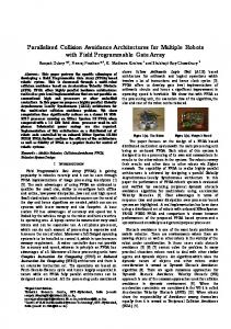
Fig. 2. TCAS interrogation sequence in a non threat intruder situation
Fig. 1.
AIS surveillance strategy
2) Aviation: TCAS [8] relies on the secondary surveillance radar (SSR). By means of this radar, a TCAS equipped aircraft interrogates other aircraft in its vicinity and listens for the transponder replies. Computer analysis of these replies determines which aircraft represent potential collision threats. Consequently Traffic Advisories (TA), in TCAS I, and resolution advisories (RA), in TCAS II and III, can be provided. The TCAS basic functionality conforms a serie of steps. • The aircraft announce their presence via squitter, i.e, a burst of data sent without being prompted by an interrogating radar. A short downlink message containing the aircrafts address is sent periodically. • When an aircraft realizes another aircraft (intruder) is in its vicinity, it interrogates the intruder asking it for its altitude. At the same time the radar calculates the distance to the intruder and its speed. • Taking into account the gained information, the aircraft evaluates whether the intruder is a threat or could be a threat in short time. Steps 2 and 3 are illustrated in Fig. 2, 3, 4. • In order to control threats, immediate threats, depicted in Fig. 3, are often interrogated, while potential threats, illustrated in Fig. 4 are less frequently interrogated. • If TCAS II or TCAS III are used, and an immediate threat is detected, the aircraft and the intruder perform a coordinated communication to reach an agreement about the most suitable resolution advisory as can be seen in Fig. 3. ADS-B [12] conforms the evolution of TCAS. Based on the Global Positioning System (GPS), an aircraft can automatically broadcast its identification address,
Fig. 3.
TCAS interrogation sequence in a threat intruder situation
GPS derived latitude and longitude, altitude and the 3-D velocity as depicted in Fig. 5. The transmission of ”intention” will be included as well. This broadcast information can be picked up by the Air Traffic Controller (ATC) and other aircraft in the range, to track aircraft more precisely than with radar [9]. Consequently it is possible to display this information on the cockpit display without the involvement of ground station equip-
Fig. 4. TCAS interrogation sequence in a potential threat intruder situation
ment and alert the pilot in case of danger.
Fig. 5.
ADS-B surveillance strategy
3) Road Transport: The Car 2 Car Communication Consortium [13] aims to establish an open European industry standard for the ad-hoc communication between vehicles and vehicles to infraestructure, which is currently in the development phase. Although the scope of C2C is very wide, it will offer among others safety applications for collision prevention. The cars are equipped with various types of sensors. These sensors may for instance detect the abrupt braking of the vehicle and a short distance to the preceding vehicle. Together with the position determined by a GNSS receiver this information is broadcast to the vehicles in the vicinity which may detect the presence of a traffic jam by exploiting the received information as illustrated in Fig. 6. In order to extend the network, multihop is implemented. Therefore the range is not limited to the communication range, which is relatively short.
sity or message length is supported. The first option to implement is the simpler broadcast protocol. However, if the message length or maximum permitted density would be a restriction, which is not the case in a first asessment, a point to point communication should be considered. On the other hand, addressed communication allows the agreement on a coordinated movement of the involved vehicles. The special railway transportation characteristics add major difficulties at this level; the manoeuvring possibilities are considerably reduced and thus, the reaction options are mainly limited to brake the train. The potential speed of the trains, combined with the reduced reaction capabilities and the geographical proximity between adjacent rails, introduces a high accuracy requirement on position determination - down to the cm level - in RCAS. Different location techniques (like GNSS and RADAR) are utilized in the maritime, aircraft and C2C surveillance systems. No further analysis of the RADAR approach is carried out, since it can be assured, that in the majority of the scenarios, no direct line of sight between RCAS modules is available. GNSS has been proved to be a suitable localization method for trains in the project RUNE (Rail User Navigation Equipment) [15], funded by the European Space Agency (ESA). However, there is no direct line of sight between satellites and RCAS modules e.g. in tunnels and when passing areas in forest. Thus other technologies - especially optical sensors, and eddy current sensors - should be incorporated in order to support satellite based positioning. Similarly, movement vectors are not just vectors in a 2-dimensional (maritime) or 3-dimensional (aeronautics) space but rely on precise trackmaps, which includes highly reliable knowledge about the status of e.g. track switches. Therefore, alike ADS-B the transmission of intention, i.e., the expected route, is of special importance in RCAS. Road transport behavior differs considerably from the railway transport, the high density of vehicles on roads that allows network extension through multihop can not be assumed in railway transport. Nonetheless, a direct interface of RCAS with C2C, supported by video would be one of the technologies utilized to avoid accidents on level crossings. III. MAC L AYER
Fig. 6.
Car-2-Car surveillance strategy
4) Applicability to RCAS: While the surveillance application of AIS, ADS-B and C2C are broadcast systems, TCAS relies on a duplex addressed communication. A point to point communication has the advantage that it allows the reduction in the number of sent messages, since the intruders that do not constitute a threat interrupt the communication. Therefore, a larger maximum den-
The MAC layer has to be carefully designed as it defines the throughput of the system. Since there is no upper layer to manage packet collisions, the MAC layer should avoid packet collisions or ensure a suitable low level of collision rate for a surveillance application. At this point appropriate message length and message rate should be selected in order to complete the specifications of the MAC layer. 1) Maritime Navigation: Maritime AIS should be capable of operating autonomously on the high seas. Consequently a distributed protocol is utilized. The
technology used for this purpose relies on a protocol called SOTDMA (Self Organized Time Division Multiple Access) [5], where the data stream is placed in defined time slots. Depending on the observed data traffic, each AIS module builds its own timetable for data transfer and reserves free time slots for its messages. In order to ensure synchronized time slots, a very precise clock is needed. Since the navigation equation provides position and time information, the GPS receiver assures the required time accuracy [6]. Coming up to the length and message rate, AIS slots are 256 bits long and it supports 4500 reports per minute. Message rate depends on the own speed, the values go from 2s for speeds over 23 knots, to 3 min for speeds under 3 knots, leading to a density of around 400 ships in range. In order to maintain the density below SOTDMA is able to reduce the range radius in necessary. 2) Aviation: Despite its low throughput, TCAS MAC protocol is based on Aloha. However, colliding transmissions can be greatly diminished by means of different techniques, i.e, interference limiting, passive detection, altitude comparison, interrogation frequency, and directional antenna. Every TCAS unit monitors the number of TCAS units within the detection range. This information is used to limit its own interrogation rate and power as necessary. In order to minimize the number of interrogations, the identity and altitude of targets is intended to be determined by passively monitoring transmissions received, afterwards, error detection and correction is applied to the received messages to reduce the number of erroneous addresses to be processed. Non-threat intruded are dismissed through altitude comparison. Additionally, TCAS units transmit an interrogation sequence nominally once per second for only those intruders that could become immediate threats. Intruders that are not likely to become immediate threats should be interrogated less frequently. Differentiation is made by means of range and estimated range rate. Finally, a directional antenna sequentially generates beams that point in the forward, aft, left and right direction. Together these beams provide surveillance coverage for targets at all azimuth angles, this way synchronous garble is reduced, i.e, the side lobe signals are ignored. On the other hand, a directional interrogation reduces the size of the interrogation region. Thus, minimizing the number of transmission collisions. Message length are 56 or 112 bits while the nominal density is 30 aircraft in range. Similarly to TCAS, ADS-B is based on Aloha. In this case, interference limitation is as well applied. Since the ADS-B extended squitter includes additionally position and speed information, its length is 112 bits instead the 56 bits of the TCAS squitter where, only identity information is transmitted. 3) Road Transport: For C2C, a derivate of IEEE 802.11 standard and CSMA/CA (Carrier Multiple Access with Collision Avoidance) protocol in the MAC
layer are proposed. One of the main limitations is the large amount of data stored by the multiple sensors it uses. Therefore, the message length is so large that the network might collapse. In order to reduce the length of the message, the inferred information of the combined sensors’ output might be sent, instead of transmitting the direct output of the sensor. 4) Applicability to RCAS: Very different approaches are carried out for each one of the analyzed systems. While AIS and C2C have well defined and standardized MAC protocols, ADS-B and TCAS utilize an ”statistical” approach. However, they all share a common feature, the MAC protocols are distributed in order to be managed autonomously. Consequently, the RCAS MAC layer will be distributed. The drawback of Aloha is its low throughput, it is extremely sensitive in high density situations like in shunting yards or train stations. However, this protocol simplifies considerably the MAC layer. Nonetheless, SOTDMA and CSMA/CA are not suitable protocols for RCAS. CSMA/CA uses the mechanism RTS/CTS (Request to send/ Clear to send) to avoid the hidden terminal problem [16]. Although it is specially designed for wireless networks, it does not work properly in broadcast communication, since the CTSs packets would collide, due to the non defined number of recipient and the disparity of the reception conditions between them. On the other hand SOTDMA does not solve the hidden terminal problem and does not assure absence of transmission collision as a contention phase exists, when a newcomer enters the network and tries to occupy a free time slot. Therefore, in the case two newcomers are simultaneously entering and by chance both occupy a free time block a transmission collision occurs. This type of collision could hardly occur if the ad-hoc networks are stable, i.e., the host’s situation in the network changes slowly. On the other hand, if too many hosts are leaving and entering continuously the network, the number of packet collisions might increase significantly. Since ships have a relative low speed and course change, SOTDMA works properly in AIS. Nonetheless, in RCAS, due to the potential high speed of trains and the relative low communication range, the network is more unstable and therefore, the protocol might be not suitable. Unlike C2C, no message length limitations are present in RCAS, in a first approach. Moreover, the user density is as well not such a restrictive parameter as in C2C. In RCAS, the MAC layer design depends strongly on the speed of the trains, parameters like message rate and maximum density are inferred from this value. This way, high speeds require a larger message rate, since the position information should be updated more frequently. Aircraft are able to move in any direction, having more reaction possibilities, which leads to a lower message rate compared to trains. However, the speed
of aircraft is higher. Therefore, the reaction time is reduced, and consequently, the message rate is increased. Summing up, the message rate for trains is expected to be in the range of the one for aircraft. IV. P HYSICAL L AYER The physical layer (PHY) conforms the main difference among the systems. In the PHY layer such important parameters as frequency, modulation, bandwidth, power, channel coding etc., are specified. In order to design it, these parameters must provide the required range and data rate which are given by the propagation channel characteristics, train speed, and necessary breaking distance of the trains. The range is defined as the maximum distance between transmitter and receiver so that a sufficient signal to noise ratio is guaranteed at the input of the receiver. The frequency f influences the decrease experimented by the signal level due to distance, which is given by the free space loss LF S equation 4πRf 2 ) (1) c where R is the distance to the transmitter and c is the speed of light. A higher transmitted power guarantees with a directly proportional relation a larger range. On the other hand, the influence introduced by the propagation channel and the protection given by the utilized digital modulation scheme, define the noise level at the receiver. The upper bound of the data rate is related with the Shannon-Hartley theorem,
The data rate is 9.6 kbps, modulated over a nominal bandwidth of 12.5 kHz. Due to the small available bandwidth a modulation such as GMSK with a high spectral efficiency is necessary. The nominal power is 12.5 W leading to a range depending on the antenna height and the environmental conditions of 15 to 30 nautical miles. TABLE I AIS FEATURES Frequency Bandwidth Modulation Power Message length Data Rate Message Rate User density MAC Layer Data Link Layer Range Attenuation characteristics
AIS1: 161.975 MHz AIS2: 162.025 MHz 25 or 12.5 kHz GMSK FM 12.5 W Variable. Dynamic report 256 bits 9.6 kbps Minimum: 2 sec Maximum: 3 min Around 400 SOTDMA HDLC 28-55 km Air, fog, rain, island
LF S = (
S ) (2) N where B expresses the bandwidth. That means that the amount of information an electromagnetic wave can S carry, is related to its bandwidth. N indicates the signal to noise ratio at the output of the demodulator and not at the input of the receiver like in the range case. This signal to noise ratio is related with the bit error rate (BER), i.e, a low signal to noise ratio leads to a high BER, thus, decreasing the data rate. Otherwise, high spectral efficient digital modulation increases the data rate automatically due to larger bits per symbol values. However, high spectral efficiency implies a larger probability of error for the same noise level at the input of the demodulator. Despite adding bits, channel coding might correct the errors in the signal due to noise, leading to an increment in the data rate. 1) Maritime Navigation: Table I summarizes the most important features of the maritime AIS [7]. In order to allow a backup frequency, to avoid interference problems and to allow channels to be shifted without communication loss from other ships, the communication is performed over two reserved VHF channels. C = B log2 (1 +
2) Aviation: As observed in Tables II and III, ADS-B and TCAS parameters are very similar. TCAS utilizes two different frequencies for the interrogation-answer sequence, while due to the absence of interrogation, ADS-B uses a single frequency. TABLE II ADS-B FEATURES Frequency Bandwidth Modulation Power Message Length Data Rate Message Rate MAC Layer Data Link Layer Range Attenuation characteristics
1090 MHz 10 MHz Pulse position 250 W 112 bits 1 Mbps 0.4-0.6 sec Interference limiting Parity check code for address < 370 km Air, clouds
The radar system used in TCAS introduces a strong limitation in range. For aircraft further away, the beam of the antenna becomes wider making the measure information less accurate. Therefore, despite the same transmitted power, the range of both systems is very different. 3) Road Transport: Due to its technological accessibility and favorable cost, a technology based on standard Wireless LAN is intended to be used in C2C [14], as summarized in Table IV. 4) Applicability to RCAS: The suitable low AIS frequency band could be reused for RCAS, since geographical separation would fulfill the interference requirements stated by the European Navigation Committee (ERC). However special consideration should be taken in
TABLE III TCAS FEATURES Frequency Bandwidth Modulation Power Message Length Data Rate Message Rate User density MAC Layer
Data Link Layer Range Attenuation Characteristics
Question: 1030 MHz Answer: 1090 MHz at -15dB, 10MHz Binary phase modulation 250 W 56 or 112 bits 1 Mbps 1 sec for threats 30 aircraft Interference limiting, passive detection, altitude Comparison, directional Antenna, timeouts Parity check code for the address 56 km Air, clouds
TABLE IV C AR 2C AR FEATURES , CURRENTLY IN DISCUSSION PHASE . Frequency Bandwidth Modulation Power Message Length Data Rate MAC Layer Range Attenuation Characteristics
5.9 GHz 20-50 MHz BPSK, QPSK, 16-QAM, 64-QAM 7-10 W 200-1000 bytes default data rate is 6 Mb/s CSMA/CA, 52 subcarriers OFDM 500 m All types of obstacles
rails close to sea or rivers where AIS is active. Reduction on AIS transmitted power would be feasible due to the shorter range of RCAS. Reusability of ADS-B and TCAS frequency is not possible, since the actual interference is already large. The power transmit by ADS-B and TCAS, is unrealistic for such a system like RCAS, which shall operate as well in urban areas. The high frequency of C2C, combined with the low transmit power, allows a very short range. On the other hand, having the same frequency would allow a direct communication of trains and road vehicles, greatly simplifying the RCAS-C2C interface, which would help tp prevent accidents on level crossings in the future. V. C ONCLUSION In this paper we have presented the basic idea of RCAS and its relation to state of the art collision avoidance in other transport systems. Broadcast and point to point communication are used in the analyzed systems, only message length and user density restrictions would justify the utilization of point to point communication in RCAS. The implemented MAC layer protocols are Aloha, CSMA/CA and SOTDMA. The special network characteristics of RCAS do not guarantee a high throughput in any of them. Finally, in the PHY layer, very different approaches are taken in the analyzed systems. For RCAS a frequency in the VHFBand, transmission power of a few watts and a message
rate in the order of the TCAS and ADS-B systems seems to be reasonable. R EFERENCES [1] Thomas Strang, Michael Meyer zu H¨orste and Xiaogang Gu ”A Railway Collision Avoidance System Exploiting Ad-hoc Intervehicle Communications and Galileo”, In: Proceedings, 13th World Congress and Exhibition on Intelligent Transportation Systems and Services (ITS 2006), London, UK, 2006-10-08 - 200610-12. [2] Gerhard Schmid, 19 Risk management in rail transportation, Casualty Risk Consulting Information for insurers, M¨unchener R¨uckversicherungs-Gesellschaft, Germany, 2006. [3] Safety Database Project Team (UIC-SDB), ”State of the Art”, The UIC Safety Data Base (UIC-SDB), Paris, 2006. [4] AIS official website, http://www.navcen.uscg.gov/enav/ais/default.htm [5] Wim F.M. van der Heijden ”AIS is coming!” ION GPS 2001, 11-14 September 2001, Salt Lake City, UT. [6] Høakam Lans, Saltsj¨obaden, ”Position Indicating System” United States Patent, Patent Number: 5506587, Apr. 9, 1996. [7] Olivier Berder, Philippe Rostaing and Gilles Burel, ”Inter-channel interference rejection for maritime AIS system” ITST 2005, 27-29 June 2005, Brest, France. [8] International Standards and recommended practices. Aeronautical Telecommunications. Annex 10, To the convention on international civil aviation. Volume IV Surveillance Radar and collision avoidance systems. 1 March 2005. [9] Vijay Ragothaman, Fariha Baloch and Ravi Pendse ”Unassited aircraft Landing via Co-operative data exchange”, 25th Digital Avionics Systems Conference, October 15, 2006, Portland, OR. [10] A. Mirri, M. Frullone, C. Carciofi ”Development of ADS-B mode S prototype system for mobile vehicles surveillance on the airport surface”, The 5th International Conference on ITS Telecommunications, June, 2005, Brest, France. [11] Berndt Cloos ”GNSS-Performance in Automatic Dependent Surveillance-Broadcast ADS-B Application”, DFS Deutsche Flugsicherung GmbH, 2003, Germany. [12] ADS-B Home Page, http://adsb.tc.faa.gov/ADS-B.htm, April 2006. [13] Car-2-Car Communication Consortium Home Page, http://www.car-to-car.org/ [14] Timo Kosch ”Technical Concept and prerequisites of car-tocar communication” Technical report, BMW Group Research and Technology, 2002. [15] A.Simsky, F.Wilms, J-P. Franckart, ”GNSS-based failsafe train positioning system for low-density traffic lines based on onedimeniosnal positioning algorithm”. 2nd ESA Workshop on Satellite Navigation User Equipment Technologies NAVITEC, 8-10 December 2004, ESA/ESTEC, Noordwijk, the Netherlands. [16] Andrew S. Tanenbaum, ”Computer Neworks”, Prentice Hall, Fourth Edition, 2003.