Comparison of DDPMSG and DFIG Concepts for Wind Turbines A. Shabani, M. Alizadeh Bidgoli
A. Deihimi
PATSAR Co. Tehran, Iran
[email protected]
Department of electrical engineering Bu-Ali Sina University Hamadan, Iran
Abstract—Through this paper, following the classification of wind turbines in four main topologies based on their generators, different aspects of the two dominant and state of the art concepts of wind turbine (WT) configurations, the direct drive permanent magnet synchronous generator (DDPMSG) type and doubly fed induction generator (DFIG) type, will be assessed. Among this investigation, it is aimed to compare different aspects of basic electrical components such as the generators, converters and controlling methods of these two WT’s structure to introduce the superior one. This comparison will include some dominant contracture of generators as well as different exerted converters and applied drives. Keywords-wind turbine; generator; converter; controlling method
I.
INTRODUCTION
During the recent decades, penetration of wind energy systems in electrical grids is undeniable and nowadays, this clean source of energy has become an inseparable part of modern electrical grids. Through these decades, almost 80s and over, different configuration of wind turbine appeared and some of them are steel working properly. Differences between these configurations show up due to different technologies which have been tailored to meet some specific characteristics. At the very beginning usage of wind energy as a source of electricity, it was the direct current generator which had been used as the producer of electrical energy [1-2]. This topology had been designed based on the need of storing the electrical energy. But of course, because of configuration of utility grids, this type did not last for a long time. Direct current topology may be found in some KW WTs now. Some of the first attempts for production of wind turbines in an industrial way were based on squirrel cage induction generator (SCIG) [2]. In this topology, a three bladed rotor (the number of blades depends on the structure and design of WT, but in most of modern WTs the three bladed rotor is the first choice) harvests the mechanical power of wind and passes it to the main shaft, which is connected to the low speed side of a multi stage gear box. The high speed side of gear box is connected to the SCIG, turning the mechanical power of wind to the electrical power [3-5]. This configuration of WTs operates at fix speed, which means that regardless of wind speed, the operational speed of WT’s rotor is fixed and determined by grid frequency, gear ratio and generator design
978-1-4799-3479-9/14/$31.00 ©2014 IEEE
[1]. The maximum increment of rotating speed in this type is about 1 or 2% [2]. Based on this fact, this type, referred as fix speed type (type A or type I). Since SCIGs are consumer of reactive power, a capacitor bank comes along with this configuration as well as soft starter. After type A, next generation of WTs was introduced based on wounded rotor induction generator (WRIG) and a variable resistor in the circuit of WRIG’s rotor. Rest of this type’s configuration is same as type A. With adding the resistors to the rotor circuit, the opportunity of increment in the speed up to 10% was provided. This topology mainly referred as partial variable speed or type B (type II) [1-2]. Since types A and B operate under low deviations of nominal speed, these two types are referred as fix speed WTs. Next generation of WTs which was introduced during late 90s, the DFIG based WTs, may be referred as a turning point in WTs industry. This configuration referred as type C (type III) is mostly similar to type B. The only difference, which is the great advantage of this type, is the circuit of generator’s rotor that instead of variable resistor, it is connected to the utility grid by use of a back to back converter [6-10]. With presence of the back to back converter, variation of rotor speed with deviation of up to ±30% of rated speed become possible. By controlling the rotor side converter, frequency of turbine output as well as it’s active and reactive power come under control. Consequently, this type of wind turbines is referred as variable speed WT. During the first decade of twenty one century this topology was the dominant configuration of mega watt WTs. Following the introduction of DFIG based WTs (type C), another configuration of WTs was tailored. The structure of this type of WT was based on elimination of drive train (main shaft and gear box), as a result, an enhancement in the total efficiency of WT was achieved as well as the decrement in maintenance price [11-12]. In this type of WTs, the rotor of WT connects to a low speed synchronous generator (SG) directly. Based on the low speed of rotating, the number of pole pairs in the SG increase and consequently the size of the SG increase too [10]. In most of the cases, the rotating field of SGs is produced by use of permanent magnet (PM) and in this way the mass of generator smoothly decreases [12]. This type of WTs mostly referred as type D (type IV). Because of fewer maintenance requirements, this type of WTs is the most suitable for offshore uses.
Since the both topologies of variable speed WTs, the DFIG based and DDPMSG based WTs, are the cases of the great interests, this paper tries to compare some electrical aspects of these two configurations such as generators in section II, power electronics in section III and their controlling algorithms in section IV. After all, the results of these comparisons will be summarized in conclusion section. II.
GENERATOR TOPOLOGY
Generator is the basic component of electrical energy production in WTs. Here are some of common parameters of WT’s generators [13-14]: •
It’s protection degree is mostly IP54 or above
•
Duty cycle of the generators should be S1
•
Voltage of most generators is 660±10% (in some multi mega watt WTs, this voltage is exceeded)
•
Ambient temperature for generator should be between -20 to +40 Celsius degree (any further temperature should be considered base on standard)
•
The altitude of installation should not exceed 1000 m above the sea level (any further altitude should be considered base on standard)
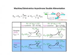
Figure 2. sub synchronous condition of DFIG based WT [10]
Two different generators of mentioned type of C and D may be explained as below. A. Doubly fed induction generator This type of generator is being used in WTs from multi hundred KW up to about 7 MW WTs [15]. Fig. 1 shows a very simple scheme of DFIG based WT’s structure. As may be seen in this figure, the circuit of stator is directly connected to the grid while the rotor circuit is connected to the same grid by use of a back to back converter (B2BC). The rotor of this type of generator is mechanically coupled with the rotor of WT using the drive train. Since the stator is directly connected to the grid, it’s frequency should remains at the frequency of the grid while the rotational speed of generator shaft varies. In order to meet this condition, the B2BC should justify the frequency and amplitude of the voltage of the rotor’s circuit in both sub synchronous and super synchronous operational condition. These conditions are shown in fig. 2 and fig. 3 as well.
Figure 3. Super synchronous condition of DFIG based WT [10]
As can be seen in fig. 2, during the sub synchronous condition the flow of power is from the grid to the generator’s rotor, but in super synchronous regime the flow of power reverses to from the rotor to the grid. In DFIG based WTs, the range of slip is mostly up to ±30% (Smax). The slip percentage is defined by winding number of rotor circuit as well as the power of B2BC. It means that the rotational speed of generator can be defined as:
ω sync (1 − S max ) ≤ ω r ≤ ω sync (1 + S max )
(1)
Which ωsync is the synchronous rotational speed and ωr is the rotational speed of rotor. The relationship between power of rotor and stator can be expressed as follow:
Protor = S × Pstator
Figure 1. simple structure of DFIG based WT
(2)
So as an instance, in a 2 MW WT with slip of 25%, the nominal power of stator, rotor and total produced power will be 1.6 MW, 0.4 MW and 2 MW in respect.
WT's rotor
Back to back converter PMSG Figure 5. Structure of RFPMSG Figure 4. Simple structure of DDPMSG based WT
B. Direct drive permanent magnet synchronousgenerator Permanent magnet synchronous generator is one of the most appealing generators of wind turbines. This type of generator can operate in any size of WTs from kilo watt (or even multi hundred watts) to multi mega watt WTs. A simple structure of this configuration is depicted in fig. 4. Most of WT’s manufacturers tailor PMSGs in direct drive WTs (in contrast with electrically excited synchronous generators-EESG) because of it’s simplicity, less maintenance cost, higher efficiency and etc. A few numbers of WTs manufacturer use electrically excited synchronous generator (EESG) in direct drive WT but they clime some other benefits out of it [12]. The PMSG which is used in a direct drive mega watt WT, in usual should be capable of operating in low speed of mostly 10 to 20 RPM (this speed range can be easily investigated through different gearless productions of WT’s manufacturer); consequently number of pole pairs and rated torque in this generator should be high. Evidently, the volume of generators increases with increment in rated torque, so the volumes of generators of gearless WTs are much higher than the geared ones. Large diameter and small pole pitch make the PMSGs more efficient and lighter [17].
Figure 6. Structure of AFPMSG [21]
There are three major topologies for PMSGs of WTs: radial flux permanent magnet synchronous generators (RFPMSG), axial flux PMSGs (AFPMSG) and transverse flux PMSGs (TFPMSG) [18-22]. The first and most popular type of PMSGs is RFPMSG. In this type of generators the flux passes through the air gap in the direction of radius of machine as shown in fig. 5. This type may be based on outer rotor or inner rotor structure. Being easily cooled is the advantage of outer rotor type, because the rotor is exposed to the air flow [18-19]. The next type of PMSGs is AFPMSG which during the recent years has been attracted some attention of generator’s designer. A double-sided slotless machine with internal stator and twin PM rotor of this type is being depicted by fig. 6. This type has much more diversities of structure compared to the RFPMSG type [21].
Figure 7. Structure of TFPMSG [22]
The last popular structure which is shown by fig. 7. complicated than two above consequently it has not made compared to the other type of
of PMSGs is TFPMSG This structure is more mentioned types and it s way to industries PMSGs [20].
III.
CONVERTER TOPOLOGIES
As mentioned before, with development of power electronic switches, usage of converter with larger capacity gets more possible which led to full converter topologies. Having this technology in the hand, controlling the power is one less thing to worry about. Besides that, the active and reactive power produced by WT is somehow under control now. In this section, firstly, the converter of DFIG based WT is to be discussed, and then the full converter of DDPMSG is explained. A. Converter of DFIG based WT Configuration of DFIG based WT as a partial converter based one, exerts a power converter consist of two back to back converter connected via a DC link. In this construction, the rotor side converter is responsible for control of generators speed based on maximum efficiency as well as keeping the frequency and voltage of terminal constant while the grid side converter controls the voltage of DC link. Both of these two converters, which are connected back to back, consist of 6 fully controlled and bidirectional switches such as IGBT. Most common used topologies of bidirectional switches are common collector, common emitter and full bridge diode [23]. These three topologies are shown in fig. 8 as well. This point should be mentioned that some other topologies of converters have been investigated through different published material in order for being used in WTs, such as multi level converter, matrix converter [2], [9], [24], and so forth, but since these different types of converter have not been used industrially so far, they will not be mentioned in this paper. A schematic of combination of generator and converter of DFIG based WT is depicted in fig. 9.
Figure 9. combination of generator and converter of
DFIG based WT
Figure 10. combination of generator and converter of DDPMSG based WT
B. Converter of DDPMSG based WT WTs with PMSG topology are full converter based, which means that the capacity of this converter in same as whole WT and whole the produced power have to pass to grid via it. The topology of DDPMSGs converter is mostly same as the DFIGs one, back to back converter. In this configuration the grid side converter is responsible for DC link voltage control as well as reactive power regulation of the grid (in this case, it is customary to set a specific point of grid as the target point) while the other one, the generator side converter is exerted for controlling the stator voltage simultaneously with rotor speed control. Switches used in this converter are same as the ones used in DFIGs converter which are illustrated in fig. 8. Just like DFIG based WT, different types of converter have been investigated in many papers [2], [24-25], which are not used industrially and so, not to be explained here. Fig. 10 shows the common topology for combination of generator and converter of DDPMSG based WT. IV.
CONTROLLING ALGORITHMS
One of the most important duties of controlling systems in modern WTs, is tracking the maximum points of mechanical power [1-2]. As can be perceived from fig. 11, any wind velocity has a curve of power over different rotational speed of WT’s rotor [26-27].
Figure 8. different types of switches used in back to back converters of both DFIG and DDPMSG based WT; a) common collector, b) common emitter, and c) full bridge diode
subscripts d and q, indicate the direct and quadrature axis components, respectively. The subscripts s and r indicate stator and rotor quantities, respectively. The superscript " ' " shows that the parameters are transferred to the stator side. The generator’s torque can be achieved by the following equation [25]:
Te =
3P (λqs idr′ − λds iqr′ ) 4 Ls
(6)
By aligning the d axis of reference frame with stator flux, the q component of stator flux will be zero, consequently the torque of generator may be controlled just by q component of rotor current [6-10], [25]. Figure 11. Power curve of wind velocities from 3 to 22 m/s over different rotational speed of WT’s rotor
Based on equation 3, by controlling the electrical torque of generator, it is possible to justify the rotating speed of WT which leads to optimal power being achieved [26-27].
Tgen − Tm′ = J equal
dω gen dt
.
d Vdr′ = −rr′idr′ − (ω − ω r )λqr′ + λdr′ . dt d Vqr′ = −rr′iqr′ + (ω − ω r )λdr′ + λqr′ . dt
(4)
λdr′ = −( Lr′ + LM )idr′ − LM ids . λqr′ = −( Lr′ + LM )iqr′ − LM iqs .
(7)
λd = − Ld id − λm λq = − Lq iq
(8)
Where:
In these equations descriptions of all the parameters are same as DFIG one, and λm is the flux linkage of permanent magnet. Based on these equations the generator torque may be expressed by following equation:
Te =
Which:
λds = −( LS + LM )ids − LM idr′ . λqs = −( LS + LM )iqs − LM iqr′ .
d λd dt d Vq = −rs iqs + ωr λd + λq dt
Vd = − rs ids − ωr λq +
(3)
A. DFIG This generator may be explained by the following equations [10], [25]:
d Vds = −rs ids − ωλ qs + λds . dt d Vqs = −rs iqs + ωλ ds + λqs . dt
B. PMSG Permanent magnet synchronous generator, due to using magnets in its rotor, can be described by simpler equations as follow [10], [25], and [28]:
[
3 P (Ld − Lq )id iq + iq λm 2
]
(9)
By setting the reference frame correctly, d component of stator current will be zero and the torque can be controlled just by it’s q component. (5)
Which V is the voltage, r is the resistance, i is the current, ω is the rotational speed of the synchronous reference frame, ωr is the rotor electrical angular speed, Lm is the mutual inductance, Ls and Lr are the stator and rotor leakage inductance, respectively, while λ is the flux linkage. The
V.
DISCUSSION
This paper investigates basic electrical components of two dominant topologies of wind turbine; DFIG type and DDPMSG type. Table I summarizes some important advantages and disadvantages of both topologies, which highly influence the selection or proper one for any specific site. During the last decade, DDPMSGs were more expensive compared to DFIGs, but its price is decreasing due to new technology of refining the rear earth elements of magnets [29].
TABLE I.
DFIG
DDPMSG
SOME ADVANTAGES AND DISADVANTAGES OF DFIG AND DDPMSG BASED WT
Advantage • Less vulnerability against high torque stress because of gearbox and higher speed • Smaller generator and converter • Lower purchasing price • Fewer active components • Higher efficiency due to lower losses • More cost effective over the time • More controllable due to full converter
So, obviously in the soon future, the best solution for wind turbines can be the DDPMSG ones. Besides that, from this table it can be inferred that for hardly accessible sites, let’s say offshore sites, the best solution is using the one with lower need of maintenance, which is DDPMSG. VI.
CONCLUSION
In this paper, two dominant types of modern WTs from electrical viewpoints of generator, converter and controlling system have been investigated. Based on DDPMSGs advantages over DFIGs, which are mostly because of elimination of drive train, lower maintenance cost, higher efficiency, and so forth, it is supposed that during this decade, exertion of DDPMSG based wind turbines of multi mega watt capacity, be expanded widely. REFERENCES [1] [2]
Erich Hau, "Wind turbines." Berlin, Germany: Springer, 2006 T. Ackermann, "Wind Power in Power Systems." New York, UK: John Wiley & Sons, 2005 [3] D.S. Koussa, M. Haddadi, M. Belhamel, S. Hadji, S. Nouredine,“ Modeling and simulation of the fixed-speed WECS (wind energy conversion system): Application to the Algerian Sahara area” journal of Energy , 2010, 4116-4125 [4] J.L. Rodrı´guez-Amenedo, S. Arnaltes, M.A. Rodrı´guez, “Operation and coordinated control of fixed and variable speed wind farms” journal of Renewable Energy, 2008, 406–414 [5] J.Ekanayake and N. Jenkins, “Comparison of the Response of Doubly Fed and Fixed-Speed Induction Generator Wind Turbines to Changes in Network Frequency”, IEEE TRANSACTIONS ON ENERGY CONVERSION, VOL. 19, NO. 4, DECEMBER 2004 [6] A. Petersson et al.” Modeling and experimental verification of grid interaction of a DFIG wind turbine”, IEEE TRANSACTIONS ON ENERGY CONVERSION, VOL. 20, NO. 4, DECEMBER 2005 [7] Hee-Sang Ko, Gi-Gab Yoon, Nam-Ho Kyung, Won-Pyo Hong, “Modeling and control of DFIG-based variable-speed wind-turbine” Electric Power Systems Research 78 (2008) [8] Hee-Sang Ko, Gi-Gab Yoon, and Won-Pyo Hong, "Active Use of DFIG-Based Variable-Speed Wind-Turbine for Voltage Regulation at a Remote Location," IEEE Trans, Power systems, VOL. 22, NO. 4,pp. 1916-1925, NOVEMBER 2007 [9] H. S.Ko, “Supervisory voltage control scheme for grid-connected wind farms,” Ph.D. dissertation, Dept. Elect. Comput. Eng., Univ. British Columbia, Vancouver, BC, Canada, 2006. [10] Ion Boldea, "Variable speed generators." Boca Raton, FL: Taylor & Francis, 2006.
Disadvantage • More complicated controlling system • Higher maintenance cost due to using drive train • Higher losses due to numerous components specially drive train • Some logistic and assembling problems • Demagnetizing problems in high temperature • More expensive due to permanent magnets
[11] Deok-je Bang, HenkPolinder, “Transverse Flux Permanent Magnet Machines” , Dutch Wind Workshops, Delft university of technology, October 2008 [12] HenkPolinder, Frank F. A. van der Pijl, Gert-Jan de Vilder, Peter J. Tavner “Comparison of Direct-Drive and Geared Generator Concepts for Wind Turbines”, IEEE TRANSACTIONS ON ENERGY CONVERSION, VOL. 21, NO. 3, SEPTEMBER 2006 [13] IEC 60034, rotating electrical machines – rating and performance, 12thed, 2010 [14] IEC 61400, wind turbines-design requirements, 3rded, 2005 [15] Available at: http://www.vem-group.com/en/productscomponents/medium-and-high-voltage/renewable-energy/productrange.html [16] B. Beltran, M.E.H. Benbouzidand T. Ahmed-Ali, “High-Order Sliding Mode Control of a DFIG-Based Wind Turbine for Power Maximization and Grid Fault Tolerance" Electric Machines and Drive Conference, 2009. [17] H. Polinder, D. Bang, H. Li, Z. Chen, “concept report on generator topologies, mechanical and electromagnetic optimization”, Delft University of Technology, Aalborg University, 2007 [18] D. Bang, H. Polinder, G. Shrestha, J.A. Ferreira, “Review of Generator Systems for Direct-Drive Wind Turbines”Delft University of Technology, 2007 [19] H. Li, Z. Chen, “Overview of different wind Generator systems and their comparisons” IET Renewable Power Generation, 2008 [20] D. Bang, H.Polinder, “Transverse Flux Permanent Magnet Machines” Dutch Wind Workshops, Delft University of Technology, 2008 [21] J.F. Gieras, R. Wang, M.J. Kamper “axial flux permanent magnet brushless machines” 2th edition, Springer, 2008 [22] M. R. Dubois, “Optimized Permanent Magnet Generator Topologies for Direct -Drive Wind Turbines,” Ph. D. dissertation, Delft Univ., The Netherlands, 2004 [23] M. Alizadeh Bidgoli, A. Soori, M. TavakoliBina ‘‘A New phase sequence Detector for the Three-Phase Rotary Loads’’ IEEE conference PEDSTC 2011. [24] J. A. Baroudi, V. Dinavahi_, A. M. Knight, “A review of power converter topologies for wind generators” journal of Renewable Energy 32, 2007 [25] M. Abbes, J. Belhadj, A. B. AbdelghaniBennani, “Design and control of a direct drive wind turbine equipped with multilevel converters” Renewable Energy 35, 2010 [26] A. Shabani, A. Deihimi,M. AlizadehBidgoli, M.A.Dour “Simple Fast Algorithm for Maximum Power PointTracking of DFIG Based Wind Turbine”IEEE Fifth POWER INDIA Conference, new Delhi, 2012 [27] A. Shabani, H.R. Karami “A Fast Model of Doubly Fed Induction Generator Based Wind Turbine”, 2nd International Conference on Electric Power and Energy Conversion Systems , Sharjah, UAE, 2011 [28] P. C. Krause, O. Wasynczuk, and S. D. Sudhoff, “Analysis of Electric Machinery and Drive Systems” Hoboken, NJ: Wiley, 2002. [29] Electron energy corporation, PA, USA: http://www.electronenergy.com