Eugeniusz KURGAN AGH University of Science and Technology
Comparison of different force calculation methods in DC dielectrophoresis Abstract In this paper two-dimensional dielectrophoresis is described. First electric field distribution in particle and surrounding fluid is calculated and next stresses acting from both sides suspension-particle boundary are calculated. These values are fundamental for force calculation in twodimensional dielectrophoresis and in simulation velocity distribution in interdigitated electrodes. Streszczenie. W tej publikacji omówiono zjawisko dielektroforezy w dwóch wymiarach. Najpierw odpowiednie równania pola zostaną analitycznie rozwiązane, a następnie zostaną wyprowadzone wzory na wartość tensora naprężeń Maxwella działającego na obie strony cząsteczki. Wielkości te mają podstawowe znaczenie w obliczaniu sił i momentów działających na cząsteczkę oraz na wyznaczanie rozkładu prędkości w urządzeniach do separacji cząstek.(Porównanie różnych metod obliczania sił w DC dielektroforezie)
Keywords: dielectrophoresis, Maxwell stress tensor calculation Słowa kluczowe: dielektroforeza, tensor naprężeń Maxwella.
Introduction In comparison to electrophoresis, by which we understand particle motion due to the force resulting from coupling between an applied external electric field and a charge particle, dielectrophoresis has the disadvantage that the polarization forces acting on polarized particle are quite weak. In general, efficient particle manipulation in microelectrode arrangement requires taken into account other factors, such as viscous, buoyancy, and electrohydrodynamic forces. This constitutes complicated system of mathematically coupled different physical fields, which results in mutually coupled system partial differential equations. From practical point of view only numerical methods can give from practical point of view satisfactory results. Based on the measurement of electric and dielectric properties, a further study of selective segregation and purposeful manipulation of micro- or nanostructures of living organisms can be achieved. The phenomenon of dielectrophoresis (DEP) was first defined by Pohl [1] as the motion of neutral but polarizable particles subjected to nonuniform electric fields. DEP provides an increased measurement precision and sensitivity in the detection of cells with different dielectric properties, without any need for labeling them. Two different methods electric force computation in dielectrophoresis is presented. The first is based on equivalent dipole method, which is easy to use, but in some situations not accurate [2, 3]. The second one is based on Maxwell stress tensor and gives in all possible situations accurate results, but is much more cumbersome in implementation. All materials from electrical point of view is composed of positive and negative charges which experience an electrostatic force when is placed in an electric field. In a uniform electric field, electrically neutral particles experience a dielectric polarization, but no net force. In a nonuniform electric field, however, forces acting on polarized charges are not balanced, and a motion called dielectrophoresis (DEP) occurs. There are actually two types of dielectrophoresis involving particles suspended in a medium: positive DEP – where the particles move toward the region of stronger electric field, and negative DEP – where the fluid surrounding the particles experience a stronger attractive force than the particles, which causes the suspended particles to be pushed toward the area of weaker electric field There are many reasons for studying a behavior of particles and fluid globules immersed fluid suspension and placed in electric fields. Among different the chemical engi-
neering applications [2] are the determination of forces acting on droplets exiting electrospray nozzles, the enhancement of heat and mass transfer in emulsions by the imposition of electric fields [3], electrically driven separation of particles techniques [4], dielectrophoretic and electrorotational manipulation of living and death cells [5], and the control of electrorheological fluids [6]. Despite this growing importance of dielectrophoresis is, little attention has been paid to the theoretical and analysis. Although dielectrophoresis is only possible in strong divergent electric fields, theoretical analyses are usually based on equations derived from uniform field behavior. The calculation of DEP force acting on particle has been reported as a difficult task unless in many cases simplifying assumptions and very simple geometries are considered [8] and is usually based on the dipole approximation first introduced by Pohl [1] The Finite Element Method (FEM) is useful method for analyzing electromagnetic fields in devices, because these can model complicated geometries and non-linear electric properties with relatively short computing time. In spite of these advantages, in many papers have been proved that obtaining an accurate force or torque from FEM computation can be inaccurate, particularly when geometry is enough complex, such as in the case of dielectrophoretic traps with multiple particles. Unfortunately, force and torque calculations are influenced by the approximate nature of the discretisation used in FEM meshes. In the Maxwell’s stress method of calculating the force and torque the stress distribution occurs from meshes used for field solution. In the Maxwell’s Stress Tensor (MST) method, it is suggested that the total force acting can be calculated by surrounding a given object by closed surface around the field sources and integrating the MST over the whole surface. The use of the standard Maxwell stress approach requires that the integration path or surface should be fully closed, and situated entirely in linear material. In this publication Maxwell’s stress method is used to evaluation of force acting on both sides of dielectric particle immersed in dielectric fluid. Comparative study of computational inaccuracies is considered. Equivalent dipole method The simulated chamber is modeled as a twodimensional model, where we need to consider only a single pair of electrodes, one with positive Uz = 10 V and one with zero voltage. The extension of the interdigitated elec-
PRZEGLĄD ELEKTROTECHNICZNY (Electrical Review), ISSN 0033-2097, R. 88 NR 8/2012
11
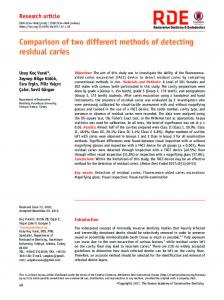
trode array beyond the considered region can be simulated by applying periodic boundary conditions to the left and right of the problem boundary model. Fig. 1 shows a crosssectional geometry, which includes the substrate and channel covers, the interdigitated electrodes, and a fluid. A
j 0 n
substrate
C
e1
E periodic boundary conditions
e2
E periodic boundary conditions
particle FDEP
a B
a
j Uz
h
j0
b
0.5b D
(7)
V1diel r ,
r02 2 1 E0 cos r 2 1
The above equation describes potential distribution generated by single dipole, so dielectric cylinder in external uniform field one can replace by equivalent dipole with electric moment value
(8)
p
2 r021 2 1
2 1
E0
The force acting on two-dimensional dipole has the same form as for three-dimensional one. The force acting on twodimensional dipole is thus given by
fd p E r
r021 2 1 2 E 2 1
Fig. 1. Computational domain together with geometrical dimensions.
(9)
Let us assume that two dimensional cylinder with permittivity ε2 is immersed in external medium with permittivity ε1. Moreover in the region number one exists uniform electric field with electric field strength E0 directed perpendicular to z axis and extending from minus to plus infinity. Let V1 denotes potential in surrounded dielectric with permittivity ε1 and V2 in the cylinder. Potential outside the cylinder, when r ∞, can be calculated along r axis as
This is the force density which falls on one unit length in z 2 direction. Expression of the E is function of potential V and its derivative 2
(10)
V V E2 x y
2
so after some manipulations we have (1)
V1 (r, ) E dr E0 cos dr E0 r cos
The Laplace equation in polar coordinates is given by
(11)
1 1 V rV 2 2 0 r r r 2
(2)
If the geometry does not depend on z, we can choose a solution that is a product of functions which only depend on the radius r and angle
V (r, ) R(r ) ( )
(3)
what when introduced in (2) gives (4)
2 d dR r 1 d 0 r R r dr dr d 2
(5)
(6)
r2 V1 r, r 0 2 1 E0 cos r 2 1 V2 r, r
21 E cos 2 1 0
where V1(r, ) and V2(r, ) are potentials in surrounding dielectric and in particle, respectively. Potential generated by dielectric cylinder is equal V1(r,) minus exciting field
V 2V V 2V 2 a 2 y x yx y y
In end effect the components of the force acting on particle have the values: (12)
V 2V V 2V f1 2C a1 2 y xy x x
(13)
V 2V V 2V f2 2C a 2 2 x xy y y
r
This equation can be solved by variable separation method giving as a result
V 2V V 2V E 2 2 ax 2 y xy x x
where constant C is given by (14)
C 1
2 1 2 1
r02
Maxwell stress tensor method Let us now derive close form of surface force density f acting on unit area when unit normal vector to the surface is given. Maxwell stress tensor Tij for electric field is given by (15)
1 Ti j Ei E j E 2 i j 2
The surface force density t is given by (16)
3 3 3 f T n T jk nr a j ak a r j 1 k 1 r 1
12
PRZEGLĄD ELEKTROTECHNICZNY (Electrical Review), ISSN 0033-2097, R. 88 NR 8/2012
In the above equations indexes i, j, k = 1, 2, 3 replace, for convenience, coordinates x, y and z. Because 3
E E ja j
(17)
j 1
3
n nja j j 1
then
1 3 f Ek nk E E 2 n 2 k 1
(18)
The expression in parenthesis is equal to the scalar product E and n, thus the surface force density has value
1 f E n E E 2n 2
(19)
One needs to calculate force densities on both sides of the particle-suspension boundary. Let us assume that suspension has number 1 and particle as number 2. Then equation (19) gives us for both sides of the boundary:
1 f1 1 E1 n1 E1 1 E12 n1 2
(20)
1 f 2 2 E2 n 2 E2 2 E22 n 2 2
(21)
The force is obtained by calculating surface integral around surface charge density induced in the particle by external field. It is assumed that there are not volume induced charges inside particle. Apparently unit normal vectors on both sides of the particle-suspension boundary have opposite sign, so because n1n and n2−n we have (22) f
(2)
1 E1 n E1 2 E2 n E2
1 1 E12 2 E22 n 2
Now, both vectors E1 and E2 can be resolved into two components: perpendicular and tangential to the boundary. (23)
E1 E1n n E1t t
E 2 E2 n n E2 t t
where n is a normal and t tangential vectors to the boundary. Boundary conditions on both side the boundary have following form (24)
E1t E2t
1 E1n 2 E2 n
This is the force acting on particle, where under integration sign field in particle is taken into account. This equation one can apply both in two-and three-dimensional problems. Let us now eliminate in (22) not field in suspension with index 1 but instead field in particle with number 2. The force is obtained by calculating surface integral around surface charge density induced in the particle by external field. The boundary condition gives
E2 n
(27)
1 E 2 1n
This allows us to eliminate components of electric field in suspension. In this case E2n. After some manipulation we have finally (28)
f (1)
1 1 2 1 E12n E12t n 2 2
and total force acting on particle described by field calculated in suspension and evaluated on suspension-particle boundary is given by (29)
F (1)
1 1 2 1 E12n E12t n ds 2 S 2
According with Newton’s third law both forces F(1) and F(2) should be equal. Illustrative example The simulated chamber is modeled as a two-dimensional model, where we need to consider only a single pair of electrodes, one with positive Uz = 10 V and one with zero voltage. The extension of the interdigitated electrode array beyond the considered region can be simulated by applying periodic boundary conditions to the left and right of the problem boundary model. Figure 2 shows a cross-sectional geometry, which includes the substrate and channel covers, the interdigitated electrodes and a fluid. The finite element calculations was done for following geometrical dimensions: A-B = 60 μm, A-C = 160 μm, a = 40 μm, b = 40 μm, h = 4 μm. Cylindrical dielectric particle has radius r1 = 3 μm and relative permittivity ε2 = 50. The fluid, where particle moves, has permittivity ε1 = 5. Computed electric field distribution is shown in Fig.2. Both x-component and y-component are given in logarithmic scale. The force acting on dielectric particle is not proportional to modulus of electric field, but instead to gradient of this field.
This allows us to eliminate components of electric field in suspension. In this case E1n. (25)
f (2)
1 2 1 2 E22n E22t n 2 1
and total force acting on particle and described by the field obtained in particle and calculated on particle-suspension boundary is given by
(26)
F (2)
1 2 1 2 E22n E22t n ds 2 S 1
Fig. 2. Electric field strength E in computational domain. The length of the vectors are in logarithmic scale
PRZEGLĄD ELEKTROTECHNICZNY (Electrical Review), ISSN 0033-2097, R. 88 NR 8/2012
13
(35)
fd 3.113a x 9.135a y [μN]
Fig. 3. Electric field strength on both sides of suspension-particle boundary
Fig. 5. Electric stress x-component acting on suspension throughout particle on suspension-particle boundary
Fig. 4. Electric stress acting on suspension throughout particle on suspension-particle boundary
In Figure 3 electric field strength on both sides of the suspension-particle boundary is given. These values directly are used in equations for Maxwell stress tensor, which acts on both sides of the boundary. In Figure 4. Electric stress acting on suspension throughout particle on suspension-particle boundary is presented. Figure 5 shows electric stress x-component acting on suspension throughout particle on suspension-particle boundary. The total force acting on particle computed from (26) formula has value (30)
F (2) 1.114a x 3.460a y [μN]
and from equation (29) (31)
F
(1)
Conclusions In this article, cylindrical particle in uniform electric field perpendicular to the particle was considered. One can see that differences in calculation of forces acting on dielectric particle immersed in dielectric fluid a comparable. The error is not greater than 5%. Maxwell stress method can be applied to particles of any shape but equivalent dipole method only for cylindrical or spherical particles. For grater values of particle radius the difference between stress calculated on Maxwell stress tensor method and equivalent dipole method is greater. This is caused by the fact that bigger particle disturbs the field in greater degree. REFERENCES [1] [2] [3]
[4]
[5]
[6]
1.157a x 3.483a y [μN] [7]
Force calculating from equivalent dipole method is given by
fd 1.120a x 3.288a y [μN] For particle radius r1 = 5 μm this forces have following
[8]
(32)
values:
[9]
P o h l , H . A ., , Dielectrophoresis, Cambridge University Press, Cambridge, England. (1978) Z u k o s k i , C . F . I V , Material properties and the electrorheological response, Ann. Rev. Mater. Sci., 23, (1993), 45-78 Mahaworasilpa T.L, Goster H.G.L and George E . P ., Forces on biological cells due to applied alternating (AC) electric fields, Biotechim. Biophys. Acta, 1193, (1994), 118–26 W a n g X . , W a n g X - B . , G a s c o y n e P . R . C . , General expressions for dielectrophoretic force and electrorotational torque derived using Maxwell stress tensor method, J. Electrostatics, 39, (1997), 277–95 D e B o r t o l i M . J . , S a l o n S . J ., Computation of forces and torque in electromagnetic devices using the finite element method, ICEM'90, ,MTI, USA, (1990), pp.699-705. H a r r i s M . T . a n d B a s a r a n O . A ., Capillary electrohydrostatics of conducting drops hanging from a nozzle in an electric field, J. Colloid. Interface Sci., 161, (1993), 389-413 S c o t t T . C ., Use of electric fields in solvent extraction: a review and prospectus, Sep. Purif. Meth., 18, (1989), 65-109 P t a s i n s k i K . J . , K e r k h o f P . J . A . M . , Electric field driven separations: phenomena and applications, Sep. Sci. Techno., 27, (1992), 995-1021 K u r g a n E . , Forces acting on multilayer dielectric particle in DC dielectrophoresis, Electrical Review, no 5, 2011, 92 - 95
(33)
F (2) 3.496a x 10.242a y [μN]
Authors: Dr hab. inż. Eugeniusz Kurgan, prof. nz., Akademia Górniczo-Hutnicza, Katedra Elektrotechniki i Elektroenergetyki, al. Mickiewicza 30, 30-059 Kraków, E-mail:
[email protected]
(34)
F (1) 3.535a x 10.410a y [μN]
The correspondence address is:
[email protected]
14
PRZEGLĄD ELEKTROTECHNICZNY (Electrical Review), ISSN 0033-2097, R. 88 NR 8/2012