supercritically reflected S waves largely between the Moho and free ... observed at distances of up to a few thousand kilometers in ...... physics 59, 1882â1893.
Bulletin of the Seismological Society of America, Vol. 96, No. 3, pp. 1091–1113, June 2006, doi: 10.1785/0120050159
Comparison of Different One-Way Propagators for Wave Forward Propagation in Heterogeneous Crustal Wave Guides by Li-Yun Fu
Abstract Crustal wave guides are usually heterogeneous on many scales, some of which can be investigated for regional phases by one-way approximation methods. The advantage of one-way propagation methods is the greater saving of computing time and memory, often up to several orders, than the full-waveform numerical methods. By slicing a half-space crustal wave guide into a number of slabs perpendicular to the propagation direction, Wu et al. (2000) formulate a wide-angle pseudoscreen method for the SH half-space problem, which leads to a generalized screen propagator (GSP) for simulating Lg propagation. In this article we introduce a broadband constant-coefficient propagator for the SH half-space problem, which accounts for wide angles in large-contrast media while allowing implementation using Fourier transforms alone. Particular attention is paid to the first-order separation-of-variables screen propagator (SVSP1) that significantly improves the split-step Fourier (SSF) method for large lateral variations at the cost of one more Fourier transform in each slab. Advancing wave fields by SVSP1 is actually a linear interpolation in the wavenumber domain between two split-step terms. We benchmark the SSF, GSP, and SVSP1 synthetic seismograms against the full-waveform boundary-element synthetics for flat, belling, and necking crustal wave guides, which shows that the SVSP1 method can model the Lg phase and the mantle wave (head wave) quite well in both travel time, energy, and waveform for most common mantle velocity perturbations. These numerical comparisons also demonstrate some limitations (especially in waveform) of the one-way propagation methods to model the Lg code attributed by forward scatterings as a result of lateral irregularities of the Moho. Introduction The theoretical and numerical exploration of regional wave propagation in various crustal wave guides has been extensively studied for different geological and geophysical environments during the past several decades. For instance, the most prominent regional phase Lg that samples the continental crust can be treated as a sum of higher-mode surface waves (Knopoff et al., 1973; Kennett, 1983), or multiple supercritically reflected S waves largely between the Moho and free surface (Bouchon, 1982). Lg propagation can be observed at distances of up to a few thousand kilometers in the frequency range 0–25 Hz. A comprehensive review (Campillo, 1990) on earlier studies of the crustal phase Lg summarizes the observations and numerical simulations for path effects of complicated lateral variations on Lg propagation and attenuation characteristics. Several typical approaches have existed that are oriented to Lg numerical simulation for a laterally heterogeneous wave guide. For instance, the coupled mode method (Kennett, 1984; Maupin and Kennett, 1987; Kennett, 1998) represents the wave train as a superposition of modal contributions for the flat-layered
reference structure and incorporates the effect of lateral variations into the matrices of reflection and transmission coefficients of the different modes. In general, full-waveform methods are very time consuming for Lg simulation of high frequencies at far regional distances. For an event at a far regional distance up to several thousand kilometers with some sections involving complex geological structures, Fu and Wu (2001) develop a section-by-section approach in which the full-waveform boundary-element (BE) method models the relatively short sections with complex media, whereas the one-way, half-space GSP method handles the sections with smooth media. The wave-field output of the previous section is used as the wave-field input to the next section to complete the entire crustal wave-guide computation. The division of sections minimizes the possible multiple backscattering between sections, so that the transmission between sections can be treated by “one-way” approximation. In some regions, the crustal heterogeneities might be relatively smooth spatially at seismic wavelengths and one-
1091
1092
L.-Y. Fu
way approximation to regional wave propagation can be applicable. The major Lg energy in a crustal wave guide is actually carried by forward-propagating waves bouncing up and down between the free surface and the Moho. These waves become dominant by small wavenumbers beyond the critical angle, trapped in the crustal wave guide in the form of guided modes. The small-angle approximation and the neglect of backscattered waves in simulations, therefore, will not change the main features of regional waves in some stable continental wave guides. Based on this fact, Wu et al. (1996, 2000) introduce a one-way, half-space generalized screen propagator (GSP) for modeling the main characteristics of Lg (2D SH case) in heterogeneous crustal wave guides. The method is based on the wide-angle pseudoscreen propagator that incorporates a finite-difference (FD) implementation for a large-angle compensation term into the Fourier matching techniques. The wave guide is sliced into thin slabs perpendicular to the Lg-propagation direction (i.e., horizontal direction). The main advantage of the one-way GSP method is the saving of computing time and memory while preserving the main dynamic properties of Lg. Because of many attractive properties of the Fourier matching techniques, in particular, for solving long-range/ 3D wave-propagation problems, we propose here to generalize this family of algorithms, enhancing their accuracy for large-angle waves in significant lateral heterogeneities while preserving the algorithmic structure of the classical split-step Fourier (SSF) propagator (Stoffa et al., 1990) or the phasescreen method (Wu, 1996). Another purpose of this article is to provide a preliminary appraisal of one-way approximation to regional phases through numerical examples. We derive a separation-of-variables screen propagator (SVSP) from scattering theory based on the generalized Lippmann– Schwinger integral equation that accurately superposes incident, boundary-scattering, and volume-scattering waves for piecewise heterogeneous media (Fu, 2002). An operator K(x,y) is said to be separation-of-variables if it can be deN composed in the form K(x,y) ⳱ k⳱1Ak(x)Bk(y), where the functions Ak(x) are linearly independent and so are the functions Bk(y). From the Fredholm integral equation theory, we know that in many cases a non-separation-of-variables kernel can be approximated by a separation-of-variables kernel as a partial sum of the Taylor (or other) series expansion. The solution of the Fredholm integral equation with the separation-of-variables kernel reduces to solving a system of linear equations. In this article, we will demonstrate that the separation-of-variables expression of the Fredholm integral propagator can be approximated as a nonlocal integral operator by which, likewise, the solution to one-way wave propagation in large-contrast media reduces to a Fourier matching solution. The tactic generally raises questions of the nature of the convergence involved, depending on what type of series is used to expand the non-separation-ofvariables propagator. Because high-order series expansion involves heavy numerical calculations that do not give us a conspicuously simpler problem to solve than other methods,
we shall proceed rather differently with an attempt to pursue a simple approximation for one-way propagation. We start by describing a generalized Lippmann– Schwinger integral equation formulated from the space domain to the wavenumber domain. Next, the one-way version of the Lippmann–Schwinger integral equation is derived. Several dispersion relations are formulated for discussing various screen-type propagators. We also discuss Fourier FD solutions by which we find that the extra implicit FD implementation to remove the paraxial phase error can be replaced by separation-of-variables operator approximations. Finally, we derive the Fourier-transform-based matching solution for the separation-of-variables screen propagator. Through the applications of the SSF, GSP, and SVSP methods to simulating regional phases in heterogeneous media, we discuss their propagation accuracy and algorithm performance by comparison with the full-waveform BE method.
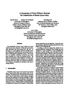
Generalized Lippmann–Schwinger Integral Equation Wave propagation in a heterogeneous crustal wave guide can be formulated as the superposition of incident, boundary-scattering, and volume-scattering waves, which can be accurately expressed as the generalized Lippmann– Schwinger integral equation that incorporates the boundary scattering into the traditional Lippmann–Schwinger integral equation. To formulate one-way approximations from the generalized Lippmann–Schwinger integral equation, we slice the heterogeneous crustal wave guide into several heterogeneous slabs perpendicular to the propagation direction and formulate the generalized Lippmann–Schwinger integral equation inside a heterogeneous slab. Figure 1 depicts the geometry of such a heterogeneous
兺
Figure 1.
The geometry of a heterogeneous slab sliced from the crustal wave guide.
1093
Comparison of Different One-Way Propagators for Wave Forward Propagation in Heterogeneous Crustal Wave Guides
slab with the thickness Dx. r is the position vector. The slab, occupying a region X, is bounded by the uppermost boundary C0, a left flat interface C1, a right flat interface C2, and an artificial bottom boundary C� to form a closed boundary C ⳱ C0 Ⳮ C1 Ⳮ C2 Ⳮ C�. The artificial bottom boundary C� is assumed to extend to infinity. Suppose a known wave on C1 is advanced along the x-axis direction from C1 to C2. The interaction of the wave with acoustic media includes not only the boundary scattering by C0, C1, and C2, but also the volume scattering by volume heterogeneities inside the slab. Seismic displacement vector u(r) in the source-free slab satisfies the following elastic wave equation (Aki and Richards, 1980; Wu, 1994) �[k(r)䉮•u(r)] Ⳮ � • [ l(r)(�u(r) Ⳮ u(r)�)] Ⳮ q(r)x2u(r) ⳱ 0,
(1)
where the k(r) and l(r) are the Lame´ moduli and q(r) is the density of the medium. The linearity of this equation allows the solutions to be decomposed into P and S waves. For sufficiently high frequencies the terms with derivatives acting on k(r) and l(r) may be neglected (Aki and Richards, 1980), and the equation can be decoupled approximately into two P- and S-wave equations, assuming that the medium is smooth and the gradients of parameter variations can be neglected (Fisk and McCartor, 1991; Wu, 1994). For simplicity, the present study is restricted to the 2D SH-wave u(r), which satisfies the scalar Helmholtz equation (Aki and Richards, 1980; Wu et al., 2000) l(r)�2u(r) Ⳮ x2 q(r)u(r) ⳱ ⳮ�dl(r) • �u(r), where dl(r) ⳱ l(r) ⳮ l0 is a perturbation over the corresponding reference shear module l0 (an average over the slab). However, as B. L. N. Kennett (private comm., 2004) has pointed out the conversion of energy because of the P-SV-SH coupling for crustal wave guides, it must be stressed that the approximation solutions described in this article miss the conversion of energy between SH and P-SV waves that is one of the main features of crustal wave guides in real situations. Extension to the elastic case must be conducted in the future. For smooth medium contrasts with one-way wave propagation applicable, one can take �dl(r) ⳱ 0 and the scalar Helmholtz equation reduces to �2u(r) Ⳮ k2u(r) ⳱ 0 with the wavenumber k ⳱ x/v(r), where v(r) is the SH-wave velocity distribution over the corresponding reference velocity v0 (an average velocity over the slab). The total wave field u(r) at the location r 僆 X Ⳮ C is composed for scattering problems of u(r) ⳱ us1(r) Ⳮ us2(r).
(2)
us1(r) is the boundary-scattered field as a result of the boundary structure C and satisfies the following boundary integral equation:
us1(r) ⳱
冮 冤G(r,r⬘)q(r⬘) ⳮ u(r⬘) C
�G(r,r⬘) dr⬘, �n
冥
(3)
where �/�n denotes differentiation with respect to the outward normal of the boundary C and q(r) is the traction on C • us2(r) is the volume-scattered field by the volume heterogeneities within the slab and satisfies the following Lippmann–Schwinger integral equation: us2(r) ⳱ k20
冮 O(r⬘)u(r⬘)G(r,r⬘)dr⬘,
(4)
X
where the reference wavenumber k0 ⳱ x/v0, and O(r) is the relative slowness perturbation defined as O(r) ⳱ n2 (r) ⳮ 1 with the refractive index n(r) ⳱ v0 /v(r). These Helmholtz integral representation formulas are derived using the Green’s function G(r,r⬘) in the background medium, that is, G(r,r⬘) ⳱ iH(1) 0 (k0 |r ⳮ r⬘|)/4 for 2D problems, where i ⳱ 冪ⳮ1 and H(1) 0 is the Hankel function of the first kind and of zeroth order. Substituting equations (3) and (4) into (2) and considering the “boundary naturalization” of the integral equations, that is, a limit analysis when the “observation point” r ⳱ (x, z) approaches the boundary C and tends to coincide with the “scattering point” r⬘ ⳱ (x⬘, z⬘) when r⬘ 僆 C, we obtain the following generalized Lippmann–Schwinger integral equation:
冮 冤G(r,r⬘)q(r⬘) ⳮ u(r⬘) C
Ⳮ
k20
�G(r,r⬘) dr⬘ �n
冮 O(r⬘)u(r⬘)G(r,r⬘)dr⬘ ⳱ X
冥
冦
u(r) r 僆 X
C(r)u(r) r 僆 C, ¢ 0 r僆X
(5)
¢ ⳱ X Ⳮ C, where the coefficient C(r) ⳱ 1⁄2 for all r⬘ 僆 X for a smooth C. This is a wave integral equation that is equivalent to the Helmholtz equation and describes two-way wave propagation in the heterogeneous slab. It is a Fredholm integral equation of the second kind. Fu et al. (1997) discussed essential facts concerning its solution for both interior and exterior Helmholtz problems and conducted numerical studies of this equation based on collocation methods for wavepropagation simulation. Fu (2002) extended the numerical techniques of the equation for wave propagation in piecewise heterogeneous media that the earth presents. Because numerous matrix operations are involved and the matrix for each frequency component must be inverted, the numerical methods are computationally intensive at high frequencies for far-regional wave guides. To reduce computing time and memory, Fu and Bouchon (2004) designed four approximation approaches with the flexibility for numerical wave propagation at scales of approximation accuracies. By letting the artificial boundaries C� tend to � along the z-axis direction, the region X becomes unbounded and extends to infinity along the z-axis direction. In this case, the
1094
L.-Y. Fu
Sommerfeld boundary condition will be automatically satisfied because of the integral representation of radiating solutions. Thus, the boundary integrals on C� will vanish, that is: �G(r, r⬘) dr⬘ r 0, �n
冮 冤G(r, r⬘)q(r⬘) ⳮ u(r⬘)
冥
C�
(6) H(1) 0 (k0 |r ⳮ r⬘|) ⳱
for r ⳮ r⬘ r �. In general, the near-surface sediments of the earth present a half-space (z � 0) model for regional phases. The presence of the rugged topography as the top part of crustal wave guides complicates all these scattering phenomena as a result of most of our seismic observations either at or very near to the Earth’s surface. Figure 1 can be viewed as a half-space model by taking the uppermost boundary C0 as the free surface where the traction-free condition q(r) ⳱ 0 is imposed. Then equation (5) is reduced to
冮
C1ⳭC2
ⳮ
冤G(r, r⬘)q(r⬘) ⳮ u(r⬘) �G(r,�n r⬘)冥dr⬘ 冮 u(r⬘) C0
�G(r, r⬘) dr⬘ Ⳮ k20 �n
冮 O(r⬘)u(r⬘)G(r, r⬘)dr⬘
Gh(r, r⬘) ⳱
Ⳮ ikz(z ⳮ z⬘)] dkz ,
i 2p
�
冮
ⳮ�
(10)
kⳮ1 cos(kz z⬘) x exp[ikx |x ⳮ x⬘| Ⳮ ikz z]dkz .
(11)
h
⳱
�
冮
i 4p
ⳮ�
[kⳮ1 (12) x q(x, kz) exp(ikx Dx)] exp(ikz z) dkz ,
(7)
Gh(r, r⬘) ⳱ G(r, r⬘) Ⳮ G(r, r*),
(8)
where r⬘ ⳱ (x⬘,ⳮz⬘) is the mirror image point of r⬘ with respect to the free surface. Therefore, equation (5) can be simplified for the flat-topography, half-space model shown in Figure 1 as
冤
Gh(r, r⬘)q(r⬘) ⳮ u(r⬘)
Ⳮ k20
kⳮ1 exp[ikx |x ⳮ x⬘| x
ⳮ�
C1
r僆X
C1ⳭC2
冮
冮 G (r, r⬘)q(r⬘)dr⬘
X
For simplicity with one-way wave propagation, the present study is restricted to a flat topography. To make the boundary integral on a flat C0 vanish, the Green’s function in equation (7) can be chosen as the homogeneous half-space Green’s function:
冮
�
where kz is the vertical wavenumber and the horizontal wavenumber kx ⳱ 冪k02 ⳮ kz2 with Im[kx] � 0, then the homogeneous half-space Green’s function becomes
⳱ C(r)u(r) r 僆 C . 0
1 p
Letting Dx ⳱ |x - x⬘| and substituting equation (11) into the integrals on C1 in equation (9), we obtain
u(r) r 僆 X
冦
quite different numerical schemes. In Figure 1 we assume wave propagation along the x axis, crossing the slab from the slab entrance C1 to the exit C2, that is, assuming r 僆 C2. Applying the plane-wave representation of the Hankel function,
C1
冮
(13)
where the wave field u(x, kz) and its gradient are defined by the following cosine transforms:
冦
�
冮 u(x, z⬘)2 cos(k z⬘)dz⬘ q(x, k ) ⳱ 冮 q(x, z⬘)2 cos(k z⬘)dz⬘. u(x, kz) ⳱
�Gh(r, r⬘) dr⬘ �n
冮 O(r⬘)u(r⬘)G (r, r⬘)dr⬘ h
冮
�Gh(r, r⬘) dr⬘ �n ⳮ1 � ⳱ [u(x, kz) exp(ikx Dx)] exp(ikz z)dkz , 4p ⳮ�
u(r⬘)
冥
z
z
0 �
(14)
z
0
The corresponding inverse cosine transforms are defined as (9)
X
冦
u(r) r 僆 X
⳱ C(r)u(r) r 僆 C . 0
r僆X
Equation (9) describes wave propagation in the spacefrequency domain. Formulating it in the frequency-wavenumber domain using a plane-wave expansion will lead to
冦
1 2p 1 q(x, z⬘) ⳱ 2p u(x, z⬘) ⳱
�
冮 u(x, k )2 cos(k z⬘)dk . 冮 q(x, k )2 cos(k z⬘)dk 0 � 0
z
z
z
z
z
z
In a similar way, we can obtain the wavenumber-domain representation of the integrals on C2 in equation (9),
Comparison of Different One-Way Propagators for Wave Forward Propagation in Heterogeneous Crustal Wave Guides
冮 G (r, r⬘)q(r⬘)dr⬘ h
C2
⳱
i 4p
�
冮
ⳮ�
冮
C2
[kⳮ1 (15) x q(x Ⳮ Dx, kz)] exp(ikz z)dkz ,
u(r⬘)
�Gh(r, r⬘) dr⬘ ⳱ 0, �n
(16)
where equation (16) results from �Gh(r, r⬘)/�n ⳱ 0 when both r, r⬘ 僆 C2. The volume integral in equation (9) describes a twoway wave scattering as a result of the two-way Green’s function that can handle both primaries and multiples inside the heterogeneous slab. The equation is an implicit expression for u(r) and requires a discrete X. To avoid the discretization of the heterogeneous region inside the slab, the volume integration over the slab can be evaluated approximately as two boundary integrals over C1 and C2 by using the trapezoid rule, that is,
冮 O(r⬘)u(r⬘)G (r, r⬘)dr⬘ � h
X
Dx 2
冢冮 O(r⬘)u(r⬘)G (r, r⬘)dr⬘ h
C1
Ⳮ
冮 O(r⬘)u(r⬘)G (r, r⬘)dr⬘冣 . h
C2
(17) Substituting equation (11) into the boundary integrals preceding yields
冮
k02 O(r⬘)u(r⬘)Gh(r, r⬘)dr⬘ ⳱ X
Dxk0 8p
�
冮
ⳮ�
kxⳮ1[F(x Ⳮ Dx, kz)
Ⳮ F(x, kz) exp(ikx Dx)] exp(ikz z)dkz ,
(18) with F(x Ⳮ Dx, kz) ⳱ CTz [ik0 O2 (x, z)u(x, z)] and F(x, kz) ⳱ CTz[ik0 O1 (x, z)u(x, z)], where the relative slowness perturbations O1 (x, z) and O2 (x, z) are defined on C1 and C2, respectively, and CTz denotes the cosine transform from z to kz. This is actually somewhat a Born approximation applied to the slab. It implies that the heterogeneity of the slab is represented by that on its two interfaces and consequently requires that the slab is thin enough with respect to the wavelength of incident waves. Substituting equations (12), (13), (15), (16), and (18) into (9), and noting that each inner integral is a Fourier transform, we obtain kx u(x Ⳮ Dx, kz) ⳮ iq(x Ⳮ Dx, kz) ⳮ
Dxk0 F(x Ⳮ Dx, kz) ⳱ [kxu(x, kz) 2
Ⳮ iq(x, kz) Ⳮ
Dxk0 F(x, kz)] exp(ikx Dx). 2
(19)
1095
Equation (19) is a wavenumber-domain wave equation that describes two-way wave propagation in the heterogeneous slab, including multiple forward- and backscatterings between C1 and C2. However, solving this equation requires operator deconvolution in the wavenumber domain because of F(x Ⳮ Dx, kz). Two computational algorithms for numerical solution of equation (19) simulate two-way wave propagation. One is global elliptic method, in that supposing the displacement and traction are unknown on both of the interfaces C1 and C2, the boundary conditions of continuities for these quantities across C1 and C2 are used to simulate the reflection/transmission across these interfaces. Some mathematical description on this scheme can be related to McCoy and Frazer (1986). This method can be viewed as an extension of the generalized R/T coefficients method (Kennett, 1983) to including cross-range inhomogeneities, and hence it becomes a wavenumber-domain version of a space-domain method (Fu, 2002). The other is marching elliptic method, in that it simultaneously advances both the displacement and traction given the initial wave field on C1 . Some computational mathematics and numerical analysis on the marching elliptic method can be seen in Roache (1995). The marching elliptic method leads to an ill-posed problem, requiring either (1) a regularization that effectively filters out the evanescent portion of the spectrum or (2) a stability requirement that ultimately limits the spatial resolution. For strongly backscattering environments, such filtering can result in spurious oscillations in the wave field. In addition, both the displacement and traction cannot be independently specified on an initial plane. Given the initial wave field, the proper determination of the traction requires scattering data from the entire domain.
One-Way Lippmann–Schwinger Integral Equation As stated in the preceding section, for one-way wave propagation using matching solution techniques, further simplification should be made to equation (19) by reducing it to one-way version. From equation (19), we see that twoway wave propagation involves two terms: the displacement u(r) and the traction q(r). In the practice of seismology we do not often measure both u(r) and q(r) at a given level. The traction q(r) at the slab entrance C1 can be dropped by choosing C1 as an acoustically soft boundary (Dirichlet boundary condition), or alternatively, by choosing a one-way Green’s function (Berkhout and Wapenaar, 1989). The resulting Rayleigh-type integral representation is valid if we neglect backscatterings. In this article, we follow a different route to simplify equation (19). To account for the effects of transmission and refraction at C1 and C2 on forward-wave propagation, we need to build two boundary integral equations in the homogeneous regions immediately preceding and following the slab
1096
L.-Y. Fu
冦
冮 冤G (r, r⬘)q(r⬘) ⳮ u(r⬘)
1 u(r) Ⳮ 2
h
C 1
�Gh(r, r⬘) dr⬘ ⳱ 0, �n
冥
r, r⬘ 僆 C1
冮 冤G (r, r⬘)q(r⬘) Ⳮ u(r⬘)
1 u(r) Ⳮ 2
h
C 2
�Gh(r, r⬘) dr⬘ ⳱ 0, �n
冥
冪
2 2 4(kx Ⳮ kⳮ x ) Ⳮ (k0 DxO1(n)) 2 2 4(kx Ⳮ kⳭ x ) Ⳮ (k0 DxO2(n))
u(x Ⳮ Dx, kz) ⳱ u(x, kz) (20)
冤
冢2(k
exp i arctan
r, r⬘ 僆 C2 .
冣
k0 DxO1(n) ⳮ x Ⳮ kx )
(n) exp(ik Dx). 冢2(kk DxO Ⳮ k )冣冥 0
Ⳮ i arctan
2
Ⳮ x
x
x
(24)
Applying the plane-wave representation of the Hankel function to equation (20) results in
冦
With the Taylor series expansion of the arctangent terms inside the bracket under
iq(x, kz) ⳱ kxⳮu(x, kz)
iq(x Ⳮ Dx, kz) ⳱ ⳮkxⳭu(x Ⳮ Dx, kz),
(21)
Ⳮ where kⳮ x and kx are the wavenumbers related to the regions immediately preceding and following the slab, respectively. Substituting in equation (19) gives
Dxk0 (kx Ⳮ Ⳮ Dx, kz) ⳮ F(x Ⳮ Dx, kz) 2 Dxk0 ⳱ [(kx Ⳮ kxⳮ)u(x, kz) Ⳮ F(x, kz)] exp(ikxDx). 2
(22)
This is the one-way Lippmann–Schwinger integral equation that accounts for both the accumulated effect of forward scattering by volume heterogeneities inside a slab and the transmission/refraction between different slabs on wave amplitude and phase. The further exploration of the physics of equation (22) is necessary for assessing its accuracy in terms of refractive indices and propagation angles. We normalize the wavenumⳮ Ⳮ bers kx ⳱ kx /k0, kz ⳱ kz /k0, kⳮ x ⳱ kx /k0, and kx ⳱ Ⳮ kx /k0. For convenience, we take the refractive index n(r) of the slab as different constants n to avoid the convolution operation in F(x Ⳮ Dx, kx), implying that the following analysis within the Fourier domain proceeds by decomposing the heterogeneous slab into a series of homogeneous slabs. In this sense, equation (22) can be written as u(x Ⳮ Dx, kz) (kx Ⳮ kⳮ ik0 DxO1(n) x ) Ⳮ Ⳮ (kx Ⳮ kx ) 2(kx Ⳮ kⳭ x ) ⳱ u(x, kz) exp(ikx Dx). ik0 DxO2(n) 1ⳮ 2(kx Ⳮ kⳭ x ) (23)
冥
Wave amplitude changes when crossing the slab as a result of the difference of O1 (n) and O2 (n) on C1 and C2, respectively. The variations in both amplitude and phase can be seen by casting equation (23) in the concise form for oneway propagation
冷
冷
冷
k0 DxO1(n) k0 DxO2(n) ⱕ 1, and ⱕ 1, ⳮ Ⳮ Ⳮ k ) 2(k x x x Ⳮ kx )
(25)
we obtain
冦
冤2(k
冥
k0 DxO1(n) k0 DxO1(n) � ⳮ ⳮ Ⳮ k ) 2(k x x x Ⳮ kx )
arctan
kxⳭ)u(x
冤
冷2(k
m
Ⳮ
2 jⳭ1
兺 (ⳮ1) j 2j Ⳮ 1 冢2(k0 x Ⳮ1kxⳮ)冣 j⳱1 k DxO (n)
1
冤
(26)
冥
k DxO2(n) k DxO2(n) arctan 0 � 0 Ⳮ 2(kx Ⳮ kx ) 2(kx Ⳮ kxⳭ) m
Ⳮ
兺
冢
j⳱1
2 jⳭ1
冣
1 k0 DxO2(n) 2j Ⳮ 1 2(kx Ⳮ kⳭ x )
(ⳮ1) j
.
Taking the first-order term leads to
冪
2 2 4(kx Ⳮ kⳮ x ) Ⳮ (k0 DxO1(n)) 2 2 4(kx Ⳮ kⳭ x ) Ⳮ (k0 DxO2(n))
u(x Ⳮ Dx,kz) ⳱ u(x,kz)
冤
exp
冥
ik0 DxO1(n) ik0 DxO2(n) exp(ikx Dx). ⳮ Ⳮ 2(kx Ⳮ kx ) 2(kx Ⳮ kx⬘) (27)
From equation (27), we obtain the following Born dispersion relation for the one-way approximation solution (equation 22) to the heterogeneous slab shown in Figure 1. kx ⳱ 冪1 ⳮ kz2 Ⳮ
0.5(n21 ⳮ 1)
冪1 ⳮ k2z Ⳮ 冪d21 ⳮ k2z Ⳮ
0.5(n22 ⳮ 1)
冪1 ⳮ k2z Ⳮ 冪d22 ⳮ k2z
,
(28)
where n1 and n2 are the refractive indices on C1 and C2, ⳮ respectively, and d1 ⳱ k0ⳮ /k0 and d2 ⳱ kⳭ 0 /k0 with k0 and
1097
Comparison of Different One-Way Propagators for Wave Forward Propagation in Heterogeneous Crustal Wave Guides
kⳭ 0 are the reference wavenumbers related to the regions immediately preceding and following the slab, respectively. To make sense of this dispersion equation, we take d1 � 1 and d2 � 1 and substitute then in equation (28) to yield the following dispersion equation:
冢
k2z Ⳮ kx ⳮ
0.5(n2 ⳮ 1)
2
冣
冪1 ⳮ k2z
⳱ 1.
(29)
It follows that kx � 冪1 ⳮ kz2 for n � 1 (small perturbation) but kx � 0.5 (n2 Ⳮ 1) for kz � 0 (small angle). Compared with the exact dispersion relation: kx ⳱ 冪n2 ⳮ kz2 for given constants n, we find the Born approximation is a small perturbation approximation (fitting into its assumption) rather than a global small-angle approximation. It cannot remove the axial phase error; that is, for kz � 0, equation (29) cannot reach the exact values for any values of n except in the case of n ⳱ 1. Figure 2 shows the bad performance of the Born dispersion equation (29) for n ⳱ 0.1�0.8. One can significantly improve the Born approximation by simplifying the relative slowness perturbation O(n) ⳱ n2 ⳮ 1 � 2(n ⳮ 1),
(30)
which tends to smooth medium contrasts. Substituting into equation (29) to yield the following improved Born dispersion equation:
冢
k2z Ⳮ kx ⳮ
nⳮ1
冪1 ⳮ k2z
2
冣
⳱ 1.
Figure 2. Comparison of angular spectra of various dispersion relations: the Born (thin solid line), the improved Born (thick solid line), the SSF (dash line), and the GSP (dotted line) under a 5% relative phase error.
dual-domain Fourier numerical techniques. Further improvement can be made using equation (30), yielding the final form:
(31)
We see that kx � 冪1 ⳮ kz2 for n � 1 and kx � n for kz � 0, which agrees with the exact dispersion relation for given constants n. Figure 2 demonstrates its significant improvement over the phase-screen approximation. The simplification in equation (30), as refractive-index smoothing, extends the Born approximation to accommodate small propagation angles for arbitrarily strong-contrast media. Therefore, the matching solution techniques based on equation (31) would account for moderate perturbations and global small angles rather than weak perturbations by the standard Born approximation. Despite its better performance over the phase-screen approximation, one-way propagation by this improved Born dispersion relation (equation 31) using Fourier transforms is unstable because of the singularity when kz � 1 (large-angle waves). However, the one-way propagation by its space-domain version is unconditionally stable using diffraction summation (Fu, 2004). This spacedomain diffraction formulation differs from the traditional Kirchhoff propagator in that it accounts not only for the obliquity, spherical-spreading, and wavelet-shaping factors, but also for the relative slowness perturbation in a laterally heterogeneous slab. For a crustal wave guide with lateral velocity variations where d ⬆ 1, equation (28) is a stable structure with the
kx ⳱ 冪1 ⳮ kz2 Ⳮ
n1 ⳮ 1
冪1 ⳮ k2z Ⳮ 冪d21 ⳮ k2z Ⳮ
n2 ⳮ 1
冪1 ⳮ k2z Ⳮ 冪d22 ⳮ kz2
.
(32)
It accounts for the transmission/refraction between different slabs, whereas equation (31) will not. Equation (31) is usually derived directly from parabolic approximations to equation (1). Some previous studies have been conducted to deal with the unstable structure in equation (31) for the dualdomain Fourier numerical implementation. For instance, the problem can be circumvented by simply adding an imaginary part to kz (De Hoop et al., 2000). These methods do not work well, especially for large lateral velocity variations and high angles. Tappert (1977) straightforwardly applied the small-angle approximation 1/冪1 ⳮ k2z � 1 to equation (29) resulting in the so-called standard parabolic equation with its dispersion relation as: k2z Ⳮ (kx ⳮ 0.5(n2 ⳮ 1))2 ⳱ 1.
(33)
Using the refractive-index smoothing (equation 30) to equation (33) yields the following SSF dispersion equation: k2z Ⳮ (kx ⳮ (n ⳮ 1))2 ⳱ 1,
(34)
1098
L.-Y. Fu
which yields the present-day phase-screen method. From Figure 2, we see that the small-angle approximation reduces the benefit from the simplification (equation 30) by reducing the more accurate dispersion relation (thick solid line) to the SSF dispersion equation (dash line). With the dispersion equations (31), (32), and (34), the Fourier matching algorithms using fast Fourier transforms can be designed for one-way propagation in either moderatecontrast media or small propagation angles. Further, more accurate approximations come with the rational operator decomposition for large to strong-contrast heterogeneous slabs. Various hybrid methods that incorporate the FD scheme into the Fourier matching solutions have been proposed; for example, the split-step FD propagator (Thomson, 1990), the split-step Pade´ solution (Collins, 1993), and the Fourier FD migrator (Ristow and Ru¨hl, 1994). These rational approximations to the square-root function dispersion relation can be generally expressed as: m
kx ⳱ 冪1 ⳮ kz2 Ⳮ n ⳮ 1 Ⳮ
a (n) k 2
j z , 兺 1 Ⳮ b (n) kz2 j⳱1 j
(35)
with its coefficients varying with n. We see that equation (35) hierarchically consists of the reference phase-shift solution (the first term), the split-step correction term (the second term), and a parabolic correction term (the last term). The cross-coupling of kz and n in the last term shows that equation (35) is not a separation-of-variables operator expression and consequently requires an extra implicit FD implementation. Wu et al. (2000) slice a half-space crustal wave guide into a number of slabs perpendicular to the propagation direction and formulate the hybrid pseudoscreen propagator based on equation (35) for the SH-half-space problem, leading to a one-way, half-space GSP method for simulating Lg propagation.
Separation-of-Variables Operator Approximations Because we slice a crustal wave guide horizontally, the resulting slabs may cross many stratified structures perpendicularly and present strong heterogeneities along the z-axis direction. The Fourier matching algorithms based on equations (31), (32), and (34) may not be accurate enough for wave forward propagation in such slabs. The hybrid methods with an extra implicit FD implementation have a higher accuracy but lose many desirable properties of the Fourier methods. To avoid the extra implicit FD implementation, we consider the following separation-of-variables operator decomposition:
implementation of the Fourier transform algorithms to equation (36). The separation-of-variables operator decomposition can be made by various series expansions. In general, the tactic raises questions of the nature of the convergence involved, depending on what type of series is used to expand kx (kz , n) ⳱ 冪n2 ⳮ kz2. Because a high-order series expansion involves heavy numerical calculations that do not give us a conspicuously simpler problem to solve than other methods, we will proceed rather differently with an attempt to pursue a simple approximation to achieve an optimal trade-off between medium complexity, propagation accuracy, and computational time. We first introduce the Taylor series expansion and then rational approximations for the construction of the splitting operators. As expected, these two approaches possess mathematical properties of approximations that are quite different. Equation (28) is a separation-of-variables operator representation. It is actually the first-order approximation of the Taylor series expansion in equation (26). With the assumption of n1 ⳱ n2 ⳱ n, it can be expressed as
冢
兺 fj (kz) gj (n). j⳱1
For this we need to deal with the following two problems: construction of the splitting operators fj (kz) and gj (n) and
,
(37)
冤
u(x Ⳮ Dx, kz) ⳱ u(x, kz) Ⳮ
冥
1 F (x, kz) exp(ikx Dx). kx
(38)
Because of the second term inside the bracket, this equation takes account of the accumulated effect of forwardscattering by volume heterogeneities in the slab, but with a singularity at kx r 0. Equation (37) is also the first-order approximation of Taylor series expansion to the square-root operator by
冪n2 ⳮ kz2 ⳱ 冪1 ⳮ kz2
冪
1 Ⳮ
n2 ⳮ 1 1 ⳮ kz2
m
� 冪1ⳮ kz2 Ⳮ
兺
Aj
j⳱1
(39)
(n2 ⳮ 1)j (冪1 ⳮ kz2) 2 jⳮ1
,
under |(n2 ⳮ 1)/(1ⳮkz2)| ⱕ 1, where 1
(36)
冣
which corresponds the following one-way propagation equation:
m
kx (kz , n) �
ⳮ1
kx ⳱ 冪1 ⳮ kz2 Ⳮ 0.5(n2 ⳮ 1) 冪1 ⳮ k2z
Aj ⳱
2
(
1 2
ⳮ1
)(
1 2
ⳮ 2) L j!
(
1 2
ⳮjⳭ 1
)
.
Equation (39) is a separation-of-variables propagator formulated by the Taylor series expansion. A similar propa-
Comparison of Different One-Way Propagators for Wave Forward Propagation in Heterogeneous Crustal Wave Guides
gator can be found in Dalrymple et al. (1990) called a verywide-angle acoustic model in underwater acoustics. To investigate the global properties of equation (39), we need to evaluate its accuracy at all n values. Some modifications can be made to improve its approximation properties. Figure 3 shows the angular spectrum of equation (39), displayed as functions of n and h (propagation angle) under the relative phase error 10%. As expected, its first order represents the Born small-perturbation approximation. Improvement is made by the second order (m ⳱ 2), where the allowed propagation angle is up to 52� at n ⳱ 0.7 (the ratio of the background to true velocities is about 2/3). Equation (39) is an exact expression for uniform medium (i.e., 冪n2 ⳮ k2z ⳱ 冪1 ⳮ k2z at n ⳱ 1), but not accurate for kz ⳱ 0 (0� propagation angle). Figure 3 shows its bad performance for strongcontrast region with n � 0.1�0.45. Fortunately fewer practical velocity models for SH waves have n values lower than 0.4. Therefore its fourth-order equation (up to 65� at n ⳱ 0.7) can satisfy common purposes in seismology at the cost of significantly increasing the number of Fourier transforms in each slab. Using the approximation n2 ⳮ 1 � 2(n ⳮ 1), equation (39) becomes m
冪n2 ⳮ k2z � 冪1 ⳮ kz2 Ⳮ
2 j (n ⳮ 1) j
兺 Aj (冪1 ⳮ kz2) 2 jⳮ1 , j⳱1
the first order (m ⳱ 1) is up to 52� at n ⳱ 0.7. This implies that the SSF method could be extended to accommodate moderate lateral velocity variations if we could solve the singularity problem at kz r 1. From Figure 4a, the abnormal behavior with the higher-order approximations (m ⱖ 2) of equation (40) can be explained by Figure 4b where the approximation dispersion curves with different n values (thin lines) intersect the corresponding exact dispersion circles (thick lines) at some large wavenumber points rather than always in the small-angle regions with kz � 0. That is, the axial errors remain large for large-contrast media. The problems with the Taylor separation-of-variables operator approximation of equations (39) and (40) are the slow convergence in the lower-order terms, the low accuracy (though better than the SSF method) that causes bad perfor-
(40)
which, as expected and shown in Figure 4a, leads to a perfect result for the first-order equation by extending it to the strong-contrast region. The allowed propagation angle for
Figure 3. Angular spectra of the Taylor separationof-variables propagator with different orders (solid line) compared with the GSP (dotted line) and the SSF (dashed line).
1099
Figure 4. Accuracy analyses of the improved Taylor separation-of-variables propagator with different orders. (a) Angular spectra of the first to fourth orders (solid line) compared with the GSP (dotted line) and the SSF (dashed line). (b) Dispersion circles of the second order (thin lines) compared with the exact (thick lines) for n ⳱ 0.4 (solid line), n ⳱ 0.65 (dashed line), and n ⳱ 0.9 (dotted line).
1100
L.-Y. Fu
mance for large-contrast slabs, and the singularity at kz � 1 (high-propagation angles) that causes unstable numerical propagation for large lateral variations, high frequencies, and large propagation angles. Replacing equation (37) with equation (32) reduces the singularity to some degree as a result of velocity differences between adjacent slabs. In general, the paraxial phase error grows rapidly with increasing kz and decreasing n. In such circumstances we believe that the separation-of-variables operator approximations will be better by such fast convergent functions as rational, exponential, or logarithmic functions than the Taylor series expansion for a given number of expanding terms. In analogy to the FD-based various parabolic approximations to the square-root operator, more accurate separation-of-variables operator approximations for constructing the splitting operators in equation (36) can be obtained with the use of rational functions. At first view from the physical understanding of equation (36), the best way to construct the splitting operators fj (kz) and gj (n) might be to take gj (n) as a function of the split-step term (i.e., gj (n) ⳱ (n ⳮ 1)j) and then to approximate fj (kz) as a term of the rational functions, that is, fj (kz) ⳱ aj k2z 冫(1 Ⳮ bj k2z ), where the coefficients aj and bj do not vary with n and can be modified to reduce dispersion errors. Actually, because |kz| ⱕ 1 for one-way propagation, the term (1 ⳮ kz2)ⳮ1/2 can be approximated by the following rational expansion: m
(1 ⳮ kz2)ⳮ1/2 ⳱ 1 ⳮ
a k2
j z , 兺 1 Ⳮ bj kz2 j⳱1
(41)
where the coefficients aj and bj are independent of n. Then we have kx ⳱ 冪1 ⳮ kz2 Ⳮnⳮ1ⳮ
m
a k2
j z j 兺 2 (n ⳮ 1) . 1 Ⳮ b k j⳱1 j z
(42)
Apparently one has kx ⳱ 冪1 ⳮ kz2 for n ⳱ 1 (uniform medium) and kx ⳱ n for kz ⳱ 0 (0� propagation angle), which agrees with the case of the exact dispersion equation. In comparison with the Fourier FD solution with equation (35) where the coefficients aj and bj depend of n, equation (42) is a separation-of-variables operator representation that leads to a pure Fourier-transform-based matching solution. Because of the mathematical properties and approximation behavior of rational functions (Trefethen and Halpern, 1986; Bamberger et al., 1988), theoretically equation (42) should be well-posed especially for the lower-order terms. Because the approximation of equation (42) involves an infinite series, the computation has to be truncated. In practice, the first-order equation or, at most, the second-order equation is adequate for common one-way wave propagation in large-contrast media with large propagation angles in seismology. The detailed description of the optimization pro-
cedure to find aj and bj by various constrained optimization algorithms will be presented in the future. In this article the coefficients in equation (42) are determined numerically by simple least-squares optimization procedure. The optimization procedure can be defined as searching optimal aj and bj to minimize the following cost function: J⳱
1
u
冮 冮 0
0
E2 (h, n) d hdn ,
(43)
where u is the maximum angle designed and the dispersion error E (h, n) ⳱ 冪1 ⳮ k2z Ⳮ n ⳮ 1 m
ⳮ
a k2
兺 j x 2 (n ⳮ 1) j ⳮ 冪n2 ⳮ k2x . j⳱1 1 Ⳮ bj kx
(44)
For a quantitative assessment of propagation accuracy of the regional separation-of-variables screen propagator, Figure 5a compares the angular spectra of its first-order term (SVSP1) with the GSP and SSF propagators under a 5% relative phase error. We see that the SVSP1 works perfectly for all the n values and all propagation angles, almost approaching that of the GSP. To investigate the global properties of equation (42), we evaluate its first- and second-order approximations across three different n values by comparing their dispersion circles with the exact, GSP, and SSF dispersion relations (Fig. 5b). As expected, the approximation can be an exact expression in the small-angle pie slices (kx � 0) for all the n values. This accuracy comparison of the firstand second-order separation-of-variables screen propagators with other Fourier propagators demonstrates a quick convergence of the regional separation-of-variables approximation in the low-order terms.
Fourier Matching Algorithm with Separation-ofVariables Screen Propagators In the preceding section, we discussed separation-ofvariables operator approximations derived by the Taylor series expansion and rational approximations, respectively. In this section, these separation-of-variables screen propagators are further formulated by a Fourier-transform-based representation for numerical implementation. For a vertically and laterally heterogeneous slab spanning from x to x Ⳮ Dx in the homogeneous half-space, the Fourier matching algorithm for one-way propagation, in general, can be expressed in the frequency-wavenumber domain as ˆ kz) exp(ikx Dx) , u(x Ⳮ Dx, kz) ⳱ u(x,
(45)
where the intermediate wave field uˆ(x, kz) is different for different Fourier propagators. For the phase-shift propagator valid for vertically homogeneous slabs, we have uˆ(x, kz) ⳱
1101
Comparison of Different One-Way Propagators for Wave Forward Propagation in Heterogeneous Crustal Wave Guides
the SSF method can be extended for moderate vertical velocity variations without an extra computational cost. For large- to strong-contrast slabs, the regional separation-of-variables screen propagator with equation (42) yields the following one-way propagation equation: u(x Ⳮ Dx, kz) ⳱ u(x, kz) exp[ik0 Dx(冪1 ⳮ kz2 m
Ⳮ n ⳮ 1)] exp[ik0 Dx
a k2
兺 j z 2 (n ⳮ 1) j] . j⳱1 1 Ⳮ bj kz
(48)
Using the exponential approximation eif � 1 Ⳮ if, the second exponential term in equation (48) becomes m
exp[ik0 Dx
a k2
j z (n ⳮ 1) j] 兺 1 Ⳮ bj kz2 j⳱1 m
�1 ⳮ
aj k2z 1 Ⳮ bj kz2
兺
j⳱1 m
Ⳮ
(49)
a k2
j z j 兺 2 exp[ik0 Dx(n ⳮ 1) ] . 1 Ⳮ b k j⳱1 j z
Substituting in equation (48) yields a one-way explicit presentation of advancing wave fields: u(x Ⳮ Dx, kz) ⳱ Figure 5. Accuracy analyses of the regional separation-of-variables propagator with different orders. (a) Angular spectra of the first order (solid line) compared with the GSP (dotted line) and the SSF (dashed line). (b) Dispersion circles of the first order (thin solid line) and second order (thick solid line) compared with the exact (thick dotted line), the GSP (thick dashed line), and the SSF (thin dashed line) for n ⳱ 0.3, n ⳱ 0.65, and n ⳱ 0.9, respectively.
冦冢
1 ⳮ
m
兺 j z 2冣 j⳱1 1 Ⳮ bj kz a k2
u(x, kz) exp[ik0 Dx(n ⳮ 1)] m
Ⳮ
a k2
j z (u(x, kz) 兺 1 Ⳮ bj kz2 j⳱1
(50)
)冧
exp[ik0 Dx((n ⳮ 1) j Ⳮ n ⳮ 1)] exp(ikx Dx).
CTz [u(x, z)]. For either vertically weak-contrast slabs or small propagation angles, the intermediate wave field uˆ(x, kz) can be computed by the SSF method: uˆ (x, kz) ⳱ CTz [u(x, z) exp(ik0 Dx(n(z) ⳮ 1))] ,
(46)
where the refractive index n(z) ⳱ v0 /v(z) with v(z) being the vertically varying velocity distribution in the slab. Note that the SSF approximation can completely remove the axial phase error. Consequently it becomes a crucial step in the cascaded structure of various perturbation-slab propagators. For vertically moderate-contrast slabs, a slight modification to the SSF method results in a more accurate propagation equation (Fu, 2005): ˆ kz) exp(ik0 Dx/(1 Ⳮ kz2)), u(x Ⳮ Dx, kz) ⳱ u(x,
Setting Cj (kz) ⳱ aj k2z /(1 Ⳮ bj k2z ) and taking the first-order approximation, then equation (50) becomes u(x Ⳮ Dx, kz) ⳱ {(1 ⳮ C1(kz))u(x, kz)exp[ik0 Dx(n ⳮ1)]
(51)
Ⳮ C1(kz)u(x, kz)exp[ik0 Dx2(n ⳮ1)]}exp[ikx Dx] .
Returning the refractive index n back to n(z), the intermediate wave field uˆ(x,kz) for the first-order separation-ofvariables screen propagator can be written as: uˆ (x,kz) ⳱ (1 ⳮC1(kz))CTz [u(x,z)exp(ik0 Dx(n(z) ⳮ 1))] Ⳮ C1(kz)CTz [u(x,z)exp(ik0 Dx2(n(z) ⳮ 1))] .
(52)
(47)
where the normalized wavenumber kz ⳱ kz /k0. We see that
Note that by the SVSP1 the advanced wave fields result from a linear interpolation in the frequency-wavenumber domain
1102
L.-Y. Fu
between two split-step terms exp[ik0 Dz(n ⳮ 1)] and exp[ik0 Dz2(n ⳮ 1)]. Therefore, the SVSP1 needs one more Fourier transform in each slab than the SSF method. Note that approximation (49) tends to make numerical wave propagation unstable. Without special care in the design of the separation-of-variables screen propagator, the wave-field energy for some n values could grow during the advance of wave fields. From equation (50), a stable numerical implementation requires
|1 ⳮ
兺j Cj Ⳮ 兺j Cj exp[ik0 Dx(n ⳮ 1) j ]| ⱕ 1 .
(53)
It is not convenient to use this criterion because k0 and Dx are involved. It follows easily from equation (53) that ⎪1 ⳮ
兺j Cj Ⳮ 兺j Cj exp[ik0 Dx(n ⳮ 1) j ]⎪ ⱕ ⎪1 ⳮ 兺j Cj⎪ Ⳮ ⎪ 兺jCj exp[ik0 Dx(n ⳮ 1) j ]⎪ ⱕ ⎪1 ⳮ 兺 Cj⎪ Ⳮ ⎪兺jCj⎪ ⳱ 1 , j
if 0 ⱕ
兺j Cj ⱕ 1.
(54)
This inequality should be used as a constraint to equation (43) in the optimization procedure for searching optimal aj and bj. Apparently, advancing wave fields by equation (50) under the condition (54) will be unconditionally stable. For forward wave propagation, the total fields are updated in the forward direction. The implementation procedure of the proposed separate-variables Fourier matching algorithms can be summarized as follows: 1. Slice a half-space crustal wave guide into several slabs perpendicular to the propagation direction (i.e., along the x-axis direction). 2. Choose a reference velocity in each slab to make it a perturbation slab represented by the acoustic refractive index. 3. Cosine transform the wave fields at the entrance of each slab into the frequency-wavenumber domain. 4. Free propagate the wave fields through the slab in the frequency-wavenumber domain by multiplying a phase shift using the reference velocity. 5. Inverse cosine transform the wave fields at the exit of the slab into the frequency-space domain and interact with the split-step terms to get the transmitted fields. 6. Repeat step 3 to step 5 slab by slab for all the slabs.
Benchmark Tests of Forward Wave Propagation with Flat Crustal Wave Guide Numerical simulations are conducted to test the accuracy of the SVSP method by comparing with BE, GSP, and
SSF methods. As a result of the manner of slicing a crustal
wave guide vertically, the resulting slabs could penetrate many strong-contrast impedance interfaces. Rather than an explicit use of the boundary conditions across interfaces in the boundary integral equation numerical methods, these property discontinuities are treated in the Fourier matching solutions as perturbations over the reference property and incorporated into the screen interaction. We are largely concerned with the performance of the SVSP method to model the large-scale crustal heterogeneities that are associated with strong-contrast impedance boundaries. The Fourier matching solutions are a forward-scattering approximation by neglecting backscattered waves. To validate the SVSP’s capacity to predict large-angle forward propagation through strong-contrast interfaces, we require a suitable geometrical model that generates no backscattered waves. Figure 6 shows such a simple crustal wave guide consisting of a homogeneous crustal medium, 200 km long and 32 km thick, overlaying a flat-mantle half-space. The point source is located on the left boundary at 2.0-km depth. The wave guide generates no backscattered waves and all the wave-guide energy is carried by forward-propagating waves including mantle waves, head waves, and crustal-guided waves that bounce up and down between the free surface and the Moho. The Moho reflections and transmissions at different propagation angles with respect to the horizontal direction are the target to validate SVSP by comparison with BE, GSP, and SSF methods. The velocity distribution with Vcrust ⳱ 3.5 km/ sec and Vmantle ⳱ 4.5 km/sec corresponds to an acoustic refractive index of 0.78 that leads to different phase errors for different Fourier matching solutions. From Figure 5a, for the given n ⳱ 0.78 the allowed propagation angles when modeling the Moho under the relative phase error 5% are up to 33� for SSF, 60� for SVSP1, and 63� for GSP, respectively. The critical angle of crustal waves for this wave guide corresponds to a propagation angle of 39� with respect to the horizontal direction, that is, the waves with propagation angles less than 39� are trapped in the crustal wave guide in the form of guided modes. The crustal-guided energy is represented by small wavenumbers in the frequencywavenumber domain. Apparently the small-angle wavenumbers (ⱕ 39�) are simulated quite accurately by SVSP1 and GSP, but with a little more phase error by SSF. Based on the accuracy analysis of propagation errors of the SSF method (Huang and Fehler, 1998), however, this phase error will be translated into a small error in refraction angles, which will not affect the main characteristics of Lg. Our numerical calculations following also confirm this statement for the crustal wave guide with Vcrust ⳱ 3.5 km/sec and Vmantle ⳱ 4.5 km/sec. The main disadvantage of these Fourier matching solutions for the wave guide is that the methods cannot well model the precritical crustal wave propagation, especially for nearly vertical incidences. However, this limitation does not pose real problems for applications because regional seismograms are usually recorded at large distances. Figure 7 compares synthetic seismograms calculated by
Comparison of Different One-Way Propagators for Wave Forward Propagation in Heterogeneous Crustal Wave Guides
1103
Figure 6. A simple crustal wave guide model with receivers 1–20 at 10-km spacing along the flat free surface, indicated by small filled triangles.
BE, GSP, SVSP1, and SSF methods, respectively. The receiv-
ers 1 � 20 at 10-km spacing are set along the flat free surface, and the source function is a Gaussian derivative with the computation frequency range 0.0–1.8 Hz. The synthetic seismograms demonstrate the formation of crustal-guided waves as repetitive reflections at both the free surface and the Moho. These SH waves that are set off at the free surface and the Moho are confined in the wave guide at postcritical angles. The remarkable agreement can be seen between these solutions, which shows the validity of the Fourier matching solutions (GSP, SVSP1, and SSF) and their computation programs. Because each waveform curve in the synthetic seismograms is drawn with being scaled with respect to a maximum value determined for its simulation, these synthetic waveforms actually indicate a relative variation of the waveguide energy that cannot adequately differentiate these numerical methods for this simple wave guide. The relative total energy curves in the top panel of Figure 8 calculated by BE, GSP, SVSP1, and SSF methods, respectively, also agree well. The energy curves are scaled in each simulation with respect to the first receiver that is set at 10 km from the source to avoid the reflections from nearly vertical incidences. The comparison in Figure 7 cannot distinguish the fullwaveform BE solution from GSP, SVSP1, and SSF and yet detect the differences of computation accuracy between these Fourier matching solutions. This indicates that (1) these Fourier matching solutions can preserve a relative variation in both waveform and energy versus distance of regional phases for the standard crustal wave guide, and (2) the crustal-guided modes are dominated by small-angle wavenumbers (ⱕ 39�) that are simulated quite well even by SSF (a narrow-angle method). Based on the accuracy comparison of Figure 5, the large-wavenumber waves in the wave guide can distinguish GSP and SVSP1 from SSF. Figure 8b–e compare the performance of these Fourier matching solutions for different wavenumber components determined by the vertical wavenumber kz. We select several vertical wavenumber values that represent small-, moderate-, and large-wavenumber components of wave fields in the wave
guide. We then calculate spectral amplitude curves as a variation versus propagation distance for these vertical wavenumbers, respectively. The spectral amplitude computation for each kz is done by a summation of all frequency components that are associated with the selected vertical wavenumber. The comparisons illustrate that (1) beyond some critical value of the vertical wavenumber kz, the accuracy of SSF immediately decreases as kz increases; (2) the decreasing accuracy of SSF as the propagation distance increases (see Fig. 8d) indicates the fast accumulation of propagation errors because of the phase error of SSF for some moderate-wavenumber components; and (3) as expected, both of GSP and SVSP1 have a quite similar accuracy for most wavenumber components, with little discrepancies at large-wavenumber components (see Fig. 8e). From the vertical axes of Figure 8, we see that the large-wavenumber energy is very small in comparison with the small-wavenumber energy and will not affect the main features of Lg in this example (see the synthetic seismograms in Fig. 7). The spectral amplitude associated with the vertical wavenumber may not be enough to differentiate computation accuracies between GSP, SVSP1, and SSF because the spectral amplitude at each vertical wavenumber is attributed by many propagation angles due to frequency variations, that is, the high-frequency components with low-propagation angles and the low-frequency components with highpropagation angles contribute to the spectral amplitude for a given vertical wavenumber. To dominate the effects generated by different propagation angles, we calculate the spectral amplitude at each given propagation angle for the dominant frequency. Figure 9 compares such spectral amplitude variations versus propagation distance for the model in Figure 6, calculated by different Fourier matching methods (GSP, SVSP1, and SSF) at the dominant frequency for small (lower panel) and large (upper panel) propagation angles, respectively. As expected from the accuracy analysis in Figure 5, these three methods have similar computation accuracies for the small-angle waves, whereas for the large-angle waves GSP and SVSP1 give quite similar spectral amplitude variations versus distance, which are different from that of
1104
L.-Y. Fu
Figure 7.
Comparison of synthetic seismograms for crustal waves calculated, respectively, by BE, GSP, SVSP1, and SSF methods for the model in Figure 6. Receivers 1–20 at 10-km spacing are set along the flat free surface, and the source function is a Gaussian derivative with the computation frequency range 0.0–1.8 Hz. BEM, boundaryelement method.
SSF. From the vertical axes of the figure, the small-angle
spectral energy is about 20 times larger than the large-angle spectral energy at this computation frequency for the postcritical propagation distances. The preceding comparisons and discussions demonstrate that the Fourier matching solutions simulate the crustal waves quite well, possibly because the simulations take the crustal velocity as the reference velocity (Wu et al., 2000). First, these Fourier matching solutions can accurately simulate travel times of the crustal waves. Second, the Fourier matching methods can preserve the crustal energy for the postcritical propagation distances. Third, the crustal waveforms that represent a small-scale relative variation of the wave-guide energy (Fu et al., 2002) can be modeled quite well even for multiple forward-scattered waves in this sim-
ple wave guide. Although both the large-wavenumber and the large-angle spectral energy can differentiate computation accuracies of GSP and SVSP1 from SSF, these parts of the wave-guide energy become very weak beyond the critical angle and will not affect the main features of Lg. Wu et al. (2000) numerically demonstrate that for large velocity variations, where the large-wavenumber or large-angle waves may become more dominant, the differences between GSP and SSF are noticeable in both amplitude and arrival time of the reflected waves in the small-epicenter distances. However, for some crustal heterogeneities, such as small-scale random perturbations, the velocity contrasts are usually less than 10%. Therefore, the SSF simulations with the wave velocity in the crust as the reference velocity can be applicable in most cases to investigate the main features of Lg.
Comparison of Different One-Way Propagators for Wave Forward Propagation in Heterogeneous Crustal Wave Guides
1105
Figure 8. Comparison of spectral-amplitude variations versus distance for the model in Figure 6, calculated by different numerical methods. (a) Total energy distribution. (b)–(e) Wave-guide spectral amplitude for different vertical wavenumbers. That the mantle is modeled as a perturbation in the Fourier matching solutions turns our attention to mantle waves. With the one-way approximation, the Moho discontinuity and irregularity are treated as parameter perturbations and are incorporated into the screen interaction. Wu et al. (2000) theoretically analyze the SSF solution of a flat Moho without the free surface. They conclude that at and beyond the critical angle the propagation is exact for both the crustal waves and mantle waves (head waves) for a standard Moho (Vcrust ⳱ 3.5 km/sec. and Vmantle ⳱ 4.5 km/sec.) because the mantle wave that propagates along the horizontal direction has an exact propagation speed. For large-angle mantle waves, the accuracy of the SSF method can be improved to some degree
by wide-angle generalized screen approximations. A general accuracy analysis for various generalized screen approximations can be found in De Hoop et al. (2000). Our research below confirms the previous conclusion and, further, more quantitative assessment is conducted with various velocity contrasts. Validation of the Fourier matching methods for mantle waves of the SH-half-space problem will be addressed in association with the following two aspects: (1) the errors generated when modeling the Moho transmission causes variations in the waveform and energy distribution of mantle waves, and (2) the mantle velocity perturbation leads to travel-time errors of mantle waves. Figure 10 compares synthetic seismograms for mantle
1106
L.-Y. Fu
Figure 9.
Comparison of wave-guide spectral amplitudes at different propagation angles versus distance for the model in Figure 6, calculated by different Fourier matching methods (GSP, SVSP1, and SSF). The wave-guide spectral amplitudes at a frequency of 1.0 Hz are calculated for propagation angles 10� (lower panel) and 50� (upper panel), respectively.
waves calculated, respectively, by BE, GSP, SVSP1, and SSF methods for the model in Figure 6. Receivers 1–11 at 10km spacing with the first receiver at 100 km are set along a horizontal line located under the Moho by 28 km. The synthetic seismograms show two groups of waves that propagate in the mantle. The first group propagating almost along the horizontal direction will influence the upgoing crustal waves by updating the incident field in the mantle. The remarkable agreement of the first group between these four graphs implicates a precise propagation for head waves by Fourier matching methods as a result of critical and postcritical reflections. The second group is excited at the Moho by the repetitive reflection in the crust and could be largeangle mantle waves depending on the velocity contrast across the Moho. The remarkable discrepancies between the full-waveform BE solution and these three Fourier matching solutions are observed for the second group of waves in both waveform and energy distribution. These may result from (1) the limited accuracy of GSP, SVSP1, and SSF for largeangle forward propagation in the mantle, and (2) the innate limitation of one-way approximation. The noticeable limitation of one-way approximation can be demonstrated because the three Fourier matching solutions present fewer differences on the mantle seismograms in Figure 10. At present, one-way propagators are developed with an attempt to reduce phase errors of forward wave propagation in laterally varied media, with less attention to the amplitude variations of waves. A one-way propagator is generally designed with its amplitude less than one for stable numerical calculations, which may not adequately describe the amplitude aspect of
forward wave propagation especially for multiple forward scatterings. It will attenuate wave components with large wavenumbers. Most of the attenuation occurs near the evanescent region (high wavenumbers). From the viewpoint of parabolic approximations it seems that attenuating the waves is certainly better than amplifying them (Claerbout, 1970). Theoretically, the effect of one-way approximation on wave amplitudes for forward wave propagation has not yet addressed clearly in the literature. Numerical simulations shown in Figures 7 and 10 demonstrate that one-way approximation models first arrivals quite well in both phase and amplitude for forward wave propagation in both the reference and perturbed media. Negative effects on the amplitude aspect come with multiple forward-scattered waves that become worse for forward propagation in the perturbed media than in the reference medium. Figure 10 does not present much difference in both phase and amplitude between GSP, SVSP1, and SSF. Based on the accuracy comparison of Figure 5, the travel-time errors between these Fourier matching methods can be dominated by adjusting computation frequencies and wave-guide configuration. We compute the synthetic seismograms of mantle waves for the model in Figure 6 with different crustal and mantle velocities. Four velocity contrasts marked in Figure 11 are modeled, respectively, by BE, GSP, SVSP1, and SSF methods with the same observation configuration as used in Figure 10. In each case of the velocity contrasts, the synthetic seismogram at 150 km is selected for each numerical method. The correlation of the selected seismograms between the BE method and each Fourier matching solution
Comparison of Different One-Way Propagators for Wave Forward Propagation in Heterogeneous Crustal Wave Guides
1107
Figure 10.
Comparison of synthetic seismograms for mantle waves calculated, respectively, by BE, GSP, SVSP1, and SSF methods for the model in Figure 6. Receivers 1–11 at 10-km spacing with the first receiver at 100 km, are set horizontally under the Moho by 28 km, and the source function is a Gaussian derivative with the computation frequency range 0.0–1.8 Hz.
is made within the window of the first group of mantle waves. The results are depicted in Figure 11, where the cross-correlation function for each velocity model is plotted as a function of time shift in seconds. As expected from the accuracy analysis in Figure 5, GSP and SVSP1 lead to very small travel-time errors (around 0.1 sec, the sampling rate used in the numerical simulation) for all the velocity contrasts across the Moho, whereas SSF causes different traveltime errors depending on velocity contrasts. The travel-time errors of the SSF method increase from about 0.3 to 0.4 sec in the moderate-contrast perturbation (n ⳱ 0.78–0.67) to about 0.6–0.7 sec in the strong-contrast perturbation (n ⳱ 0.5–0.44). This range of travel-time errors for the first group of mantle waves as shown in Figure 10 is very small with respect to the about 45 sec of arrival times of the seismogram selected at 150 km, which indicates quite a precise propagation for head waves by Fourier matching methods. The travel-time errors may be quite large when simulating largeangle forward waves propagating in both the crust and mantle.
Benchmark Tests with Belling and Necking Crustal Wave Guides In the previous section, we conducted extensive numerical tests with a standard crustal wave guide to compare the SVSP1 method with various well-known numerical methods, such as BE, GSP, and SSF. These comparisons validate the precision of the SVSP1 method in terms of travel time, waveform, and amplitude for forward wave propagation of crustal and mantle waves. However, the standard crustal wave guide is a simple crustal-mantle structure that presents a flat Moho and generates no backscattered waves and forwarddiffracted waves. We now investigate how the performance of the Fourier matching solutions is affected by the presence of lateral variations in medium and structure. The models considered are the belling and necking crustal wave guides. The Moho irregularities in these wave guides affect Lg amplitude and characteristics by (1) generating forward and backward multiple scatterings that tend to remove some energy from the guided waves and (2) partly destroying the
1108
L.-Y. Fu
Figure 11.
Cross-correlation function of the BE seismogram, respectively, with the GSP, SVSP1, and SSF seismograms of mantle waves for the receiver at 150 km shown in Figure 10, plotted as a function of separation in seconds. Four graphs correspond to different crustal and mantle velocities that lead to different velocity perturbations denoted by acoustic refractive indices.
Lg-propagation manner of the multiple supercritical reflections. These effects actually become significant only when the wavelength of the incident wave is comparable to the scale of the irregularities. Here we are concerned with how well the Fourier matching solutions can model laterally varied crustal structures by comparing with the full-waveform BE solution. In this section we present some numerical examples to demonstrate the potential of the Fourier matching solutions applied to regional wave propagation in laterally varied media. Figure 12 shows a comparison of total energy attenuations (lower panel) for the belly-type wave guide (top panel), computed by BE, GSP, SVSP, and SSF methods, respectively. Energy computation is done by a summation of all frequency components of each synthetic seismogram for receivers along the flat free surface. All the energy curves are scaled in each simulation with respect to the first receiver at 100 km horizontally from the source to avoid the precritical reflections that the Fourier matching solutions cannot model well. We see that these energy curves almost approach each other for all the receivers. The Lg-wave train is mainly made up
of small-angle shear waves multiply reflected in the crust at angles greater than the critical angle. We demonstrated in the previous section that these small-angle shear waves are well modeled by the Fourier matching solutions for the standard crustal wave guide. For local irregularities presented in a crustal wave guide, as demonstrated by Bouchon and Coutant (1994), the amplitude of each individual small-angle shear wave is not significantly affected by small variations in crustal structure so that the presence of a fault does not significantly affect the total energy of the Lg phase but changes its waveform. Therefore, such a comparison of the total energy does not show much difference between these numerical methods. A comparison of synthetic seismograms between these numerical methods for crustal waves obtained 500 km away from the source is shown in Figure 13 for the belling crustal wave guide with different crustal and mantle velocities. Three velocity contrasts shown, respectively, under each graph correspond to acoustic refractive indices of 0.78, 0.67, and 0.5 that lead to different phase errors for the Fourier matching solutions to the Moho. The four waveform curves
Comparison of Different One-Way Propagators for Wave Forward Propagation in Heterogeneous Crustal Wave Guides
1109
Figure 12. Comparison of energy-attenuation curves (lower panel) calculated by BE, GSP, SVSP1, and SSF methods, respectively, for a belling crustal wave guide (top panel). The receivers at 1-km spacing are along the flat free surface with the first at 100 km. The source depth is 2 km located on the left boundary. The source function is a Gaussian derivative with the computation frequency range 0.0–1.8 Hz.
in each graph calculated by the BE, GSP, SVSP1, and SSF, methods, respectively, do show a very good agreement for the first several major arrivals across all the velocity contrasts. Some differences, especially in waveform, occur in the Lg-wave coda attributed by forward multiple scatterings as a result of lateral variations of the Moho. The disagreements in the coda between these numerical methods become dominant when the velocity contrast across the Moho is stronger. As discussed in the previous section, this can be accounted for by the nature of one-way approximation because three Fourier matching solutions (GSP, SVSP1, and SSF) give a similar waveform structure of the coda for crustal waves. Unlike the total energy of the Lg phase, the Lg waveform is, in general, the result of the interference pattern between numerous shear-wave arrivals. Relatively small lateral changes in crustal structure produce phase differences between the full-waveform BE solution and the Fourier matching solutions that change the interfering waves in phase and thus affect the waveform. The discrepancies between the full-waveform BE solution and these three Fourier matching solutions are expected to be remarkable for mantle waves because the mantle is modeled as a perturbed medium in the numerical simulations. Figure 14 shows a similar comparison of synthetic seismograms for mantle waves observed at a position located 500 km horizontally from the source and 60 km vertically from the free surface. We see some distortions for the Fourier matching solutions across all groups of waves, but with less for the primary group of waves. The waveform distortions become serious as the velocity contrast increases. We also see that GSP and SVSP1 give more accurate results than SSF in waveform, energy, and travel time. Unlike GSP and SVSP1, the SSF method systematically overestimates the Lg leakage to the mantle for all the velocity contrasts because the amplitude of mantle waves computed by SSF is abnormally large. Comparing Figures 10 and 14 illustrates the effects of large-scale crustal lateral variations
Figure 13. Comparison of synthetic seismograms for crustal waves in the belling crustal wave guide with the receiver marked by an asterisk located at 500 km on the free surface in Figure 12. These synthetic seismograms are calculated, respectively, by BEM (curve 1), GSP (curve 2), SVSP1 (curve 3), and SSF (curve 4). Three graphs correspond to different crustal and mantle velocities shown under each graph. on the Fourier matching solutions, especially in the waveform of mantle waves. Increases of wavefront distortion and wave-field complexity can also be seen clearly from laterally homogeneous (Fig. 10) to heterogeneous (Fig. 14) wave guides. The previous observations from the belling crustal wave guide can be seen in Figures 15–17 for the necking crustal wave guide. The passage of a narrow crustal wave guide (neck type) has a greater effect on Lg leakage than the broad passage (belly type), that is, more large-angle waves leak to the mantle as the passage narrows and the energy trapped in the crust is mostly associated with small-angle waves. Therefore, the energy-attenuation curves shown in Figure 15 com-
1110
L.-Y. Fu
Figure 14. Comparison of synthetic seismograms for mantle waves in the belling crustal wave guide with the receiver marked with an asterisk located at 500 km under the Moho by 28 km in Figure 12. These synthetic seismograms are calculated, respectively, by BEM (curve 1), GSP (curve 2), SVSP1 (curve 3), and SSF (curve 4). Three graphs correspond to different crustal and mantle velocities shown under each graph. puted, respectively, by the full-waveform BE and the Fourier matching solutions (GSP, SVSP1, and SSF) agree better than those in Figure 12. Because of scatterings at the edges around the neck, the Lg waveforms (especially in the coda) shown in Figure 16 across all the velocity contrasts become more complicated than those in Figure 13 for the belling crustal wave guide. The four, waveform curves in each graph calculated by BE, GSP, SVSP1, and SSF methods, respectively, show a bad agreement for the Lg-wave coda, but the first several major arrivals agree quite well between the fullwaveform and approximation solutions across all the velocity contrasts. These examples shown in Figures 12, 13, 15, and 16 demonstrate the potential of the Fourier matching solutions as a tool for modeling the main characteristics of Lg waves, the waves dominant by small wavenumbers beyond the critical angle. However, more quantitative assessment of these methods to simulate some scattering effects deduced by lateral crustal irregularities, for example, focusing/defocusing, diffraction, and interference that are attributed to the Lg coda, will be conducted theoretically and numerically in the future. For mantle waves propagating in the necking crustal wave guide, Figure 17 shows that the Fourier matching solutions cannot accurately predict wave-field complexities caused by diffractions at the edges toward the mantle, among which the SSF solution causes much more serious distortions in both waveform and energy than GSP and SVSP1 across all the velocity contrasts. In general, the Earth’s crust is composed of large-scale irregular stratified structures and small-scale volume heterogeneities. We have used the belling and necking crustal wave
guides to assess the performance of the Fourier matching solutions to large-scale lateral crustal variations. One of the advantages of these methods is the fast simulation of regional wave propagation in small-scale volume heterogeneities. Figure 18 shows several snapshots to visualize the path effects of small-scale heterogeneities in the belling crustal wave guide where a mountain root is made by smallscale random heterogeneities represented with velocity perturbations. The snapshots at 50 and 100 sec, are calculated, respectively, by SSF and SVSP1 for different random velocity perturbations in the mountain root. The dv ⳱ 15% perturbation of the 3.5 km/sec crustal velocity indicates that the mountain root will change randomly from 2.975 to 4.025 km/sec. The development of mantle waves and head waves, as well as the formation of the crustal-guided waves as repetitive reflections between the free surface and the Moho, can be seen clearly. The comparison between the snapshots for waves passing through the mountain root with and without random heterogeneities shows that the diffuse scattering in random heterogeneities increases mantle leakage, energy diffusion, and wave-field complexity. However, a clear onset with maximum amplitude in the consecutive wavefronts can be seen along the heterogeneous mountain root. The previous examples with large-scale and small-scale lateral crustal variations indicate that for Lg phases the trapping of shear energy is quite efficient, and even in the presence of lateral heterogeneities, most of the energy can still be trapped in the crust (Kennet, 1989).
Discussions and Conclusions As a modeling tool functioning between full-waveform methods and high-frequency asymptotic methods, the Fourier matching methods neglect backscatterings so that the full-wave equation can be simplified as the one-way wave equation. The main advantage of these methods is to simulate long-range wave propagation with the fast speed of computation and the great saving in computer memory while preserving the main characteristics of regional phases in heterogeneous crustal wave guides. In addition, the Fourier matching methods are immune to numerical dispersion for high-frequency waves, are easy to incorporate various Q models for studying intrinsic and scattering attenuations, and are natural to incorporate random heterogeneities in numerical simulations. In this article, we present a new wide-angle propagator for one-way propagation based on separationof-variables approximations to the one-way Lippmann– Schwinger integral equation. The separation-of-variables operator decomposition leads to a splitting operator form required for the implementation of matching solutions only using Fourier transforms. We use the Taylor series expansion and rational approximations to generate separation-ofvariables screen propagators. The former involves a slow convergence especially in the low-order terms and the operator singularity that causes unstable numerical computations. The latter leads to fast convergence in the low-order
Comparison of Different One-Way Propagators for Wave Forward Propagation in Heterogeneous Crustal Wave Guides
1111
Figure 15. Comparison of energy-attenuation curves (lower panel) calculated, respectively, by BEM, GSP, SVSP1, and SSF for a necking crustal wave guide (top panel). The receivers at 1-km spacing are along the flat free surface with the first at 100 km. The source depth is 2 km located on the left boundary. The source function is a Gaussian derivative with the computation frequency range 0.0–1.8 Hz.
Figure 16. Comparison of synthetic seismograms for crustal waves in the necking crustal wave guide with the receiver marked by an asterisk located at 500 km on the free surface in Figure 15. These synthetic seismograms are calculated respectively by BEM (curve 1), GSP (curve 2), SVSP1 (curve 3), and SSF (curve 4). Three graphs correspond to different crustal and mantle velocities shown under each graph.
terms and unconditionally stable algorithms. The first-order separation-of-variables screen propagator (SVSP1) extends the SSF method to accommodate wider angles of propagation for large lateral velocity variations at the cost of one more Fourier transform in each slab. Advancing wave fields by SVSP1 is actually a linear interpolation in the wavenumber domain between two split-step terms. We benchmark the SVSP1 method against the full-waveform BE method and other Fourier matching methods, such as GSP and SSF, for Lg-wave propagation at regional distances in the flat, belling, and necking crustal wave guides. The main conclusions can be summarized as follows.
Figure 17. Comparison of synthetic seismograms for mantle waves in the necking crustal wave guide with the receiver marked with an asterisk located at 500 km under the Moho by 28 km in Figure 15. These synthetic seismograms are calculated respectively by BEM (curve 1), GSP (curve 2), SVSP1 (curve 3), and SSF (curve 4). Three graphs correspond to different crustal and mantle velocities shown under each graph.
1. Accuracy analyses through angular spectra and dispersion circles indicate that SVSP1 has a similar accuracy to GSP for all the n values and all propagation angles. SVSP1 keeps the split-step algorithmic structure that uses Fourier transforms alone to advance wave fields, whereas GSP is a hybrid Fourier method where a continued fraction expansion to the square-root operator results in a largeangle compensation term that needs a FD implementation. 2. Numerical comparisons against the BE method for wave propagation in the flat, belling, and necking crustal wave guides show that GSP and SVSP1 have a similar accuracy
1112
L.-Y. Fu
Figure 18. Comparison of snapshots for waves passing through a crustal wave guide with a heterogeneous mountain root (top panel). The snapshots are calculated, respectively, by SSF (left panel) and SVSP1 (right panel) for the mountain root with random velocity perturbations of 0.0 and 15%, respectively. to simulate the crustal waves quite well in travel time, amplitude, and waveform for various velocity contrasts across the Moho. These wide-angle screen methods significantly improve SSF (a narrow-angle method) for predicting large-angle waves in strong-contrast media. 3. The Fourier matching methods are especially suited to investigate the main characteristics of Lg-wave propagation because the crustal-guided modes are dominated by small-angle wavenumbers. Although the large-angle wave energy in the crustal-guided modes can efficiently differentiate computation accuracies of GSP and SVSP1 from SSF, it is very small in comparison with the smallangle wave energy in most practical crustal wave guides and will not affect the main features of Lg. 4. Numerical examples for belling and necking crustal wave guides demonstrate the limitations (especially in waveform) of the Fourier matching methods to model the Lg code attributed by forward scatterings as a result of lateral irregularities of the Moho. 5. Numerical comparisons against the BE method for mantle waves in the flat, belling, and necking crustal wave guides show that the Fourier matching methods provide a quite precise propagation for head waves, but cause noticeable errors in the waveform and energy distribution of the large-angle mantle waves.
Acknowledgments This research was supported by Funds of a Hundred Outstanding Talents Plan, Chinese Academy of Sciences. Part of this material is based on the research carried out by L.Y.F. while working at the Institute of Tectonics, University of California in Santa Cruz. The article benefited from criticism of the original manuscript and valuable comments by Kees Wapenaar and two anonymous reviewers. I am deeply grateful to Ru-Shan Wu for encouragement and many insightful discussions.
References Aki, K., and P. G. Richards (1980). Quantitative Seismology. Theory and Methods, W. H. Freeman, San Francisco. Bamberger, A., B. Engquist, L. Halpern, and P. Joly (1988). Higher order paraxial wave equation approximations in heterogeneous media, SIAM J. Appl. Math. 48, 129–154. Berkhout, A. J., and C. P. A. Wapenaar (1989). One-way versions of the Kirchhoff integral, Geophysics 54, 460–467. Bouchon, M. (1982). The complete synthesis of seismic crustal phases at regional distances, J. Geophys. Res. 82, 1735–1741. Bouchon, M., and O. Coutant (1994). Calculation of synthetic seismograms in a laterally varying medium by the boundary element-discrete wavenumber method, Bull. Seism. Soc. Am. 84, 1869–1881. Campillo, M. (1990). Propagation and attenuation characteristics of the crustal phase Lg, Pure Appl. Geophys. 132, 1–19. Claerbout, J. F. (1970). Coarse grid calculation of waves in inhomogeneous media with application to delineation of complicated seismic structure, Geophysics 35, 407–418.
Comparison of Different One-Way Propagators for Wave Forward Propagation in Heterogeneous Crustal Wave Guides Collins, M. D. (1993). A split-step Pade´ solution for the parabolic equation method, J. Acoust. Soc. Am. 93, 1736–1742. Dalrymple, R. A., L. C. Munasinghe, D. H. Wood, and J. T. Kirby (1990). A very-wide-angle acoustic model for underwater sound propagation, J. Acoust. Soc. Am. 88, 1863–1876. De Hoop, M. V., J. H. Le Rousseau, and R. S. Wu (2000). Generalization of the phase-screen approximation for the scattering of acoustic waves, Wave Motion 31, 43–70. Fisk, M. D., and G. D. McCartor (1991). The phase screen method for vector elastic waves, J. Geophys. Res. 96, 5985–6010. Fu, L. Y. (2002). Seismogram synthesis for piecewise heterogeneous media, Geophys. J. Int. 150, 800–808. Fu, L. Y. (2004). Wavefield interpolation in the Fourier wavefield extrapolation, Geophysics 69, 257–264. Fu, L. Y. (2005). Broadband constant-coefficient propagators, Geophys. Prospect. 53, 299–310. Fu, L. Y., and M. Bouchon (2004). Discrete wavenumber solutions to numerical wave propagation in piecewise heterogeneous media—I. Theory of two-dimensional SH case, Geophys. J. Int. 157, 481–498. Fu, L. Y., and R. S. Wu (2001). A hybrid BE-GS method for modeling regional wave propagation, Pure Appl. Geophys. 158, 1251–1277. Fu, L. Y., Y. G. Mu, and H. J. Yang (1997). Forward problem of nonlinear Fredholm integral equation in reference medium via velocityweighted wavefield function, Geophysics 62, 650–656. Huang, L. J., and M. C. Fehler (1998). Accuracy analysis of the split-step Fourier propagator: implications for seismic modeling and migration, Bull. Seism. Soc. Am. 88, 18–29. Kennett, B. L. N. (1983). Seismic Wave Propagation in Stratified Media, Cambridge University Press, Cambridge. Kennett, B. L. N. (1984). Guided wave propagation in laterally varying media—I: theoretical development, Geophys. J. R. Astr. Soc. 79, 235– 255. Kennett, B. L. N. (1989). On the nature of regional seismic phases—I. Phase representations for Pn, Pg, Sn, Lg, Geophys. J. 98, 447–456. Kennett, B. L. N. (1998). Guided waves in three-dimensional structures, Geophys. J. Int. 133, 159–174. Knopoff, L., F. Schwab, and E. Kausel (1973). Interpretation of Lg, Geophys. J. R. Astr. Soc. 33, 389–404. Maupin, V., and B. L. N. Kennett (1987). On the use of truncated model expansion in laterally varying media, Geophys. J. R. Astr. Soc. 91, 837–851.
1113
McCoy, J. J., and L. N. Frazer (1986). Propagation modeling based on wavefield factorization and invariant imbedding, Geophys. J. R. Astr. Soc. 86, 703–717. Ristow, D., and T. Ru¨hl (1994). Fourier finite-difference migration, Geophysics 59, 1882–1893. Roache, P. J. (1995). Elliptic Marching Methods and Domain Decomposition: symbolic and Numeric Computations, CRC Press, Boca Raton, Florida. Stoffa, P. L., J. T. Fokkema, R. M. de Luna Freire, and W. P. Kessinger (1990). Split-step Fourier migration, Geophysics 55, 410–421. Tappert, F. D. (1977). The parabolic approximation method, in Wave Propagation and Underwater Acoustics, J. B. Keller and J. S. Papadakis (Editors), Springer-Verlag, New York, 224-287. Thomson, D. J. (1990). Wide-angle parabolic equation solutions to two range-dependent benchmark problems, J. Acoust. Soc. Am. 87, 1514– 1520. Trefethen, L. N., and L. Halpern (1986). Well-posedness of one-way equations and absorbing boundary conditions, Math. Comput. 147, 421– 435. Wu, R. S. (1994). Wide-angle elastic wave one-way propagation in heterogeneous media and an elastic wave complex-screen method, J. Geophys. Res. 99, 751–766. Wu, R. S. (1996). Synthetic seismogram in heterogeneous media by onereturn approximation, Pure Appl. Geophys. 148, 155–173. Wu, R. S., S. Jin, and X. B. Xie (1996). Synthetic seismograms in heterogeneous crustal wave guides using screen propagators, in Proc. of the 18th Annual Seismic Research Symposium on Monitoring a Comprehensive Test Ban Treaty, 290–300. Wu, R. S., S. Jin, and X. B. Xie (2000). Seismic wave propagation and scattering in heterogeneous crustal wave guides using screen propagators—I. SH waves, Bull. Seism. Soc. Am. 90, 401–413.
State Key Laboratory of Lithospheric Evolution Institute of Geology and Geophysics Chinese Academy of Sciences Beijing 100029, China
Manuscript received 27 July 2005.