The Kinect⢠sensor is equipped with a red-green-blue. (RGB) camera and a depth ... chain for MVD video generation using the Kinect sensor. We provide a ...
COMPLETE PROCESSING CHAIN FOR 3D VIDEO GENERATION USING KINECT SENSOR Michal Joachimiak a, Miska M. Hannuksela b, Moncef Gabbouja a
Department of Signal Processing, Tampere University of Technology, Tampere, Finland; b Nokia Research Center, Tampere, Finland ABSTRACT
The multiview-video-plus-depth (MVD) format selected for 3D video standardization describes 3D scene by video and associated depth and enables generation of virtual views through the depth-image-based rendering (DIBR) process. The Kinect™ sensor is equipped with a red-green-blue (RGB) camera and a depth sensor and it is suitable to capture synchronous video and depth streams. However, these sensors do not produce data with pixel-wise correspondence that is required by the DIBR process. In this paper we describe the process to use the Kinect device for MVD data creation. The processing includes sensor calibration, rectification of depth and texture, depth projection to the RGB camera pose, joint depth map filtering, and final projection to virtual view. As a part of this processing we describe a novel joint median filtering method that mitigates artifacts on object edges in the synthesized view, caused by depth to texture misalignments. The process presented in this paper produces an unpaired MVD representation of 3D scene, which can be utilized for enabling advanced 3D video applications. Index Terms— Kinect, depth map filtering, joint median filter, view synthesis, 3D video generation. 1. INTRODUCTION The next generation of 3D video entertainment may rely on usage of the multiview-video-plus-depth (MVD) format [1] for 3D scene representation. The MVD describes 3D scene from different viewing angles as video and associated depth. Thanks to calibration parameters and depth data, the generation of virtual views is possible with use of depthimage-based rendering (DIBR) [2]. Virtual views can be utilized as an input for autostereoscopic displays (ASDs) and in cases where the viewpoint or baseline adjustment is required on the receiver side. Variable baseline might be necessary to adjust to properties of some displays, user preferences or viewing conditions [3]. To support the growth of interest in 3D media, the Moving Picture Experts Group (MPEG) initiated standardization efforts on 3D video coding, which have been later continued by the Joint Collaborative Team on 3D Video Coding Extension Development (JCT-3V). As a
result, JCT-3V has developed extensions for the Advanced Video Coding standard (H.264/AVC) and for the High Efficiency Video Coding standard (H.265/HEVC). For example, the multiview video and depth extension (MVC+D) [4] of H.264/AVC was finalized in January 2013. The MVD format requires depth data creation. In a conventional approach the depth data is estimated in process of stereo matching [5] where available texture video components are used. This process is considered challenging and in some cases non-satisfactory to produce MVD data of acceptable quality [6]. Alternatively, MVD data can be produced by a system consisting of video and depth image sensors. In recent years, devices equipped with depth sensors have become available on the consumer electronics market. An example is the Microsoft Kinect [7] that is equipped with a video sensor, a depth image sensor and a pattern illumination light source. The depth acquisition process is conducted according to the structured light principle [8], however, that method suffers from the occlusion problem. The structured light pattern can be occluded by foreground objects in the scene causing the loss of depth information at the occluded pixels. Additionally, the depth data produced by Kinect is noisy in spatial and temporal domain. The optical axes for video and depth cameras are not parallel and their optical characteristics vary. Therefore, the texture and depth data produced with such devices does not feature pixel-wise association. The pixel-wise correspondence between texture and depth is required in case of MVD data that is used by the DIBR. The lack of pixel-wise correspondence significantly complicates the utilization of the Kinect devices for producing MVD content. In our work we regarded Kinect as a widely available texture and depth capturing platform at the consumer market and developed a software solution to enable MVD content creation with it. However, the basic principles and the processing chain utilized in our solution are applicable for other video-plus-depth capturing devices, where texture and depth sensors are separated in space and have different optical properties. A system to produce stereo image using Kinect is presented in [9]. That technique requires depth image warping to the RGB camera position. The warped depth exhibits holes which are filled with use of the discontinuity
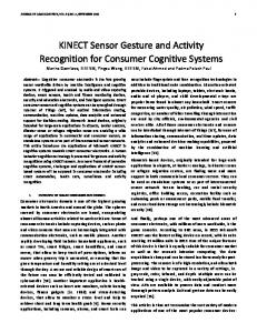
Fig. 2. On the left the depth frame acquired using Kinect. On the right the same image projected to RGB camera pose. The disocclusion artifacts are visualized in white color. novel view. Section 5 discusses future improvements and concludes the paper. 2. DEPTH ARTIFACTS
Fig. 1. The model of Kinect’s hardware with example of occluded rays illuminated by the IR projector. adaptive depth map smoothing filter [10]. Following this, a virtual depth map is used for projection of texture image to the second virtual view at the position of depth camera. The aim of this paper is to present a complete processing chain for MVD video generation using the Kinect sensor. We provide a description of depth artifacts together with their sources of origin. To mitigate these artifacts we propose a novel, computationally simple depth inpainting method and joint median filter. The joint median filter is able to remove artifacts appearing on object boundaries, visible in synthesized view as boundaries fluctuation. The filter is using a similarity metric in the texture domain to adaptively select pixels in depth, taking part in the filtering process. This method decreases the amount of flickering in the generated 3D video. In [9] the problem of flickering artifacts in video is not tackled. Also in difference to [9] the conversion for distance data to 8-bit depth data is provided. However, the most important difference to the work [9] is that our processing deals with video sequences that contain significant amount of motion, whereas [9] shows processing of the static scene generated by Kinect sensor. The rest of the paper is organized as follows. Section 2 describes artifacts in depth data acquired using the Kinect sensor and their sources of origin. Section 3 provides the details of the processing chain used for novel view generation for RGB and depth camera setup used in the Kinect. In Section 4 describes the performance of the joint median filter, depth inpainting and overall quality of the
The advantages of using the Kinect for MVD video acquisition, over the stereo matching methods, are low computational cost and depth map quality not dependent on amount of texturized object in the scene. In order to produce the MVD video format the depth data, with pixel-wise correspondence to the texture data is required. Depth images obtained by the Kinect suffer from a set of artifacts. The Infra-Red (IR) projector illuminates the scene with a pattern structure. Due to a pose difference between the structured light projector and the depth sensor, the foreground objects in a scene can partially occlude the background objects, blocking the reflected IR pattern light from reaching the depth sensor. In Figure 1 the horizontal section of the Kinect sensor model and an exemplary scene is shown. The pinhole camera model is used. The principal points CIR, CRGB and CP pertain to the IR camera, the RGB camera and the IR projector, respectively. The rays spanning between p1 and p2, coming from the IR projector are occluded by the foreground object. Effectively, the pattern is not visible in the IR sensor for rays spanning between d1 and d2. The depth corresponding to the areas where the objects are marked in white cannot be estimated. That phenomenon is exhibited in depth images in the form of areas with missing depth values called holes. An example of a depth frame with such artifacts, marked in red, can be seen in Figure 2, left. In the case of structured light systems, for objects exposed at oblique angles or with high reflectance, the depth measurement is typically erratic [8]. The holes corresponding to these areas are shown in yellow, in Figure 2, left. The specification for Kinect limits the distance for which depth readings can be considered precise. The Kinect can be configured to operate either in the so-called near mode or in the far-mode, and the operating range for depth sensing is 40cm-3m for the near mode and 80cm-4m for the far mode. The values corresponding to objects outside those ranges also create holes in the captured depth image.
Fig. 3. Depth edge fluctuation of the static object. Patches cropped from consecutive frames at the same pixel location. Finally, the depth obtained from Kinect exhibits depth to texture misalignments at object edges, and the misalignments may fluctuate over time. That type of an artifact, shown in Figure 3, causes flickering on the edges in synthesized view since pixels on the edge appear background and foreground interchangeably. View synthesis artifacts can be tolerated to some extent since Human Visual System (HVS) is able to fuse two images, so that subjective quality of stereoscopic image is closer to higher quality image [12]. However, the flickering in synthesized view, caused by texture to depth misalignment, draws visual attention and, since it is a sudden change in a suppressed image, can bring that image into dominance [13]. 3. MVD GENERATION PROCESSING CHAIN The depth and texture data produced using Kinect cannot be stored in the MVD format directly. The depth and texture data have to be rectified and calibration parameters have to be available in order to conduct DIBR. The calibration parameters are also necessary to rectify the images [11]. Since the optical properties of Kinect cameras and their relative position do not change, it is enough to execute the calibration only once for an individual Kinect. The rest of the processing steps have to be conducted for each video sequence separately. The overview of the processing chain is depicted in Figure 4. The raw distance data is inpainted and converted to the 8-bit depth data. The depth and the RGB image are rectified in order to enable projection the depth to the RGB camera pose using DIBR. After the projection step every pixel p(x,y) in RGB image has corresponding depth value d(x,y) at equal pixel coordinates. At last, after joint median filtering step the virtual view is generated with use of denoised RGB frame and projected depth. 3.1. Calibration The calibration is performed according to the method proposed in [13]. For the time of calibration the IR projector
= 0 0
(2) 0
1
is shuttered and a set of calibration images with calibration
Fig. 4. Image processing chain for 3D video generation in MVD format. target is recorded using RGB and IR cameras. As a result an intrinsic camera matrix with internal camera parameters and extrinsic camera matrix which relates world coordinate system to the camera coordinate system are estimated using [14]. The calibration assumes a pinhole camera model where a point in P=[X,Y,Z,1]T in 3D space relates to its projection p=[u,v,1]T in image space by = [ ]
(1)
where s is an arbitrary scale factor; R is rotation matrix and t is translation. The intrinsic camera matrix, shown in Equation 2, is a 3x3 matrix with focal length values in x and y directions, fx and fy, correspondingly, coordinates of
principal point [cx,cy] and α corresponding to the skewness of the two image axes. 3.2. Distance data inpainting The steps in the 3D video generation algorithm presented in Figure 4 assume that depth value is available for every pixel in the image. Missing depth values would impact depth projection and novel view generation. Thus, it is important to inpaint missing depth pixels before any other processing is executed. We propose to use a simple, computationally inexpensive method that works directly on distance values. The method works as follows. In the in case where distance value z(x,y) exceeds the far distance limit Zfar it is considered as a hole. The pixels are processed in 1D windows spanning the hole area in horizontal direction. The inpainting consists of 2 steps. In the first step the estimate of the maximum distance ZMAX for the current row y is calculated. The following equations are employed: ( , ) = (1 − ) ( − .. + , ) + ( , − 1) =
1+|
1 ( , − 1) −
( − , + )|
(3)
(4)
The index t refers to the current frame number. The distance ZAV is an average of maximum distances for the row y calculated over frame range (t-w,t+w). In the second step the inpainting candidate values are selected from the left and the right boundary of the hole area, ZL and Z R, respectively. The greater value, corresponding to further distance is selected based on the assumption that values corresponding to background should be similar to Z MAX. The following formula is used to select candidate values corresponding to a background area: |
−
| < .
(5)
The threshold T=1000 was found to provide satisfactory performance for the set of test sequences. Since depth artifacts were found to appear in background objects the aim of the candidate selection in Formula 5 is to prevent inpainting with values corresponding to objects in foreground. If inequality In Formula 5 does not hold the Zcand is not taken into account. If both left and right hole boundary values do not conform to Formula 5 or they are not available the value ZMAX is used for inpainting. 3.3. Distance to depth conversion To encode the depth and use it in DIBR process after decoding, it is required that depth data is stored using 8 bits per depth pixel. The conversion of disparity data to depth is performed according to Equation 6. Disparity value acquired by Kinect is denoted by z. The values Z far and Znear correspond to furthest and closest distance values,
d = (2 − 1) ∙
1 1
−
1
−
1
+ 0.5
(6)
respectively. These values are selected based on the depth acquisition mode and stay constant for the whole sequence. The distance to depth quantization is performed according to Equation 6. This depth representation was selected as one of the depth representation formats in MVC+D standard [4]. Selection of this formula is motivated by the need of more accurate depth representation for objects closer to the camera. The normalization to the depth range guarantees that performance of DIBR is uniform. 3.4. Rectification Even though the physical mounting of depth and texture sensors is parallel, due to inaccuracy in the production process the angle between depth and texture optical axes is not parallel. The images have to be transformed so that optical axes are parallel and image planes are coplanar. Additionally, the lines on which corresponding pixels lay – epipolar lines – should become collinear and parallel to the horizontal image axis. A set of two image transformations leading to this state is called rectification [11] and it is required to enable depth projection to the RGB camera pose and view synthesis. For accurate correspondences the rectification transformations have to take into account optical characteristics of cameras, namely focal length, principal point and distortions. The pinhole camera is modeled by the perspective projection matrix (PPM) P, composed using matrices acquired during calibration process: = [ | ]
(7)
The aim of the rectification process is to calculate the two new perspective projection matrices for IR and RGB cameras so that focal planes for both cameras become coplanar with epipolar lines collinear. After rectification intrinsic matrices for both cameras are the same. 3.5. Depth projection The DIBR used for the virtual view generation requires that the depth image represents the scene at the same camera pose as the texture image. To satisfy this requirement the depth has to be projected to the RGB camera pose. Since the depth data is represented as an image, the pixel of the rectified depth image is back-projected from the 2D image plane to the 3D world location using its own depth values and PPM for depth camera. After that the point is projected from 3D world location to a 2D texture image plane [2]. Thanks to rectification the calculation of the pixel position in virtual view for the purpose of DIBR[2] can be simplified to the following equation [16]
=
+
(8)
The xsource and xvirtual are horizontal pixel positions in the source and virtual image, respectively. The vertical pixel position y does not change. The source image is the depth image recorded by the sensor. The virtual image is the projected depth at the RGB camera pose. Value t corresponds to the distance between cameras given in mm. The value f corresponds to the focal length of the camera at the virtual viewpoint given in pixels. The value Z is the distance measure in mm to the real-world object corresponding to the pixel at location (x,y). 3.6. Joint median filter After the depth projection, the corresponding pixels in depth and texture images share the same pixel coordinates. At this point the filtering is executed to mitigate depth to texture misalignment artifacts exemplified in Figure 3. The proposed joint median filter works as follows. The new value for the depth pixel, located in the center of the filtering window is calculated as a median of depth values in the filtering window. The subset of depth pixels undergoing median filtering is determined adaptively, based on their similarity to the central pixel, according to (9). Since depth intensities may be erroneous the similarity metric is calculated as an absolute difference between pixels in the texture domain. | ( , ) − ( , )|