John R. Clymer. Applied Research Center for Systems Science. California State University, Fullerton ..... many process instances as computer memory permits.
SIMULATION http://sim.sagepub.com
Simulation-Based Engineering Of Complex Adaptive Systems John R. Clymer SIMULATION 1999; 72; 250 DOI: 10.1177/003754979907200404 The online version of this article can be found at: http://sim.sagepub.com/cgi/content/abstract/72/4/250
Published by: http://www.sagepublications.com
On behalf of:
Society for Modeling and Simulation International (SCS)
Additional services and information for SIMULATION can be found at: Email Alerts: http://sim.sagepub.com/cgi/alerts Subscriptions: http://sim.sagepub.com/subscriptions Reprints: http://www.sagepub.com/journalsReprints.nav Permissions: http://www.sagepub.com/journalsPermissions.nav Citations (this article cites 6 articles hosted on the SAGE Journals Online and HighWire Press platforms): http://sim.sagepub.com/cgi/content/refs/72/4/250
Downloaded from http://sim.sagepub.com at PENNSYLVANIA STATE UNIV on April 16, 2008 © 1999 Simulation Councils Inc.. All rights reserved. Not for commercial use or unauthorized distribution.
250-
TECHNICAL ARTICLE
Simulation-Based Engineering Of
Complex Adaptive Systems John R. Clymer Applied Research Center for Systems Science California State University, Fullerton Fullerton, California, USA
http:/ /ecs.fullerton.edu/ ~jclymer
’
1.
’
Introduction
Systems to be developed in the future will likely be more complex than in the past. The number of behaviors a system can exhibit is one measure of system complexity. A complex system can be described as a large network of communicating subsystems. A regional or national Intelligent Transportation System exemplifies such a system. If each subsystem in the network adapts its behavior to collaborate with other subsystems to achieve overall goals, such a system is called a Complex Adaptive System (CAS). In this paper a building elevator system provides an example CAS in which each elevator collaborates with others to optimize system performance. A Context-Sensitive System model that explicitly deals with the complexity of CAS is dicussed. A graphical simulation language, Operational Evaluation Modeling for Context-Sensitive Systems (OpEMCSS), assists in understanding CAS and automates most complex simulation details and semantics. OpEMCSS is distinctive from most simulation languages that have a graphical user interface in its ability to duplicate processes without having to show every instance onscreen. OpEMCSS and its use in simulation-based systems engineering of CAS are discussed.
Systems to be designed and developed in future years are likely to be much more complex than past efforts. In this context, complexity is defined as the total number of behaviors a system can exhibit. A regional or national Intelligent Transportation System (ITS) exemplifies such a complex system [1]. Any complex system can be described as a large network of communicating subsystems. If each subsystem in the network adapts its behavior to collaborate with other subsystems to achieve overall system goals, such a system is called a Complex Adaptive System (CAS). An example CAS is a network of traffic light subsystems controlling traffic flow at intersections in a city grid. Each traffic light subsystem could be designed to perceive information about traffic flow coming from each of its nearest neighbors in the network. When each traffic light subsystem adapts its traffic light timing to maintain uninterrupted traffic flow relative to its nearest neighbors, average vehicle waiting time in the entire network is reduced [2]. CAS subsystems share knowledge, and each individual subsystem adapts its local behavior based on this shared knowledge. In the traffic light network, subsystem collaboration occurs when simple traffic control rules optimize traffic flow in a local network.
Keywords: Graphical simulation, complex adaptive systems, simulation-based engineering
From collaboration within each local network emerges optimal global network performance. However, proper CAS interaction strength, coupling, and
Downloaded from http://sim.sagepub.com at PENNSYLVANIA STATE UNIV on April 16, 2008 © 1999 Simulation Councils Inc.. All rights reserved. Not for commercial use or unauthorized distribution.
feedback gain are required for the traffic network to achieve the desired emergent behavior [2-7]. Consider a CAS that consists of a network of N subsystems where each individual subsystem has M behaviors it can choose to exhibit to collaborate with the other subsystems. The overall system can select from among approximately (MN) behaviors the one that best satisfies its mission goals. Decision making required to select individual subsystem behaviors in order to collaborate with others can be distributed among all subsystems or centrally located in relatively few subsystems [2]. Given the above definition, CAS complexity in-
approximately exponentially (MN), depending system-level behavior constraints, with the number of system components N. Very complex systems can be constructed from a collection of relatively simple subsystems if these subsystems are free to secreases on
lect from any of their feasible behaviors. Understanding a CAS requires an explicit model to represent CAS interactions that result in subsystem collaboration and emergent system behavior. This paper discusses a Context-Sensitive System (CSS) model that explicitly represents CAS interactions. Systems are context-sensitive if subsystems within them require knowledge from other subsystems to operate efficiently. Most real-world systems are context-sensitive; they use shared knowledge in adapting individual subsystem behavior. Often system designers model CAS as context-free systems to reduce the complexity of the system description. In context-free systems, such as queuing systems, subsystems do not alter their behavior based on what other subsystems are doing. Decisions are based only on local knowledge, such as number of items in a queue. SLAM [8] is based on a queuing systems model. The EXTEND Discrete Event Simulation (DES) library is also based on transactions flowing through a network of queues and servers. To apply the EXTEND DES library to model CSS transitions in surface ship combat, attribute sharing and process synchronization blocks were added to the library. Modeling a CAS as a context-sensitive system need not be difficult. Operational Evaluation Modeling for Context-Sensitive Systems (OpEMCSS) is a graphical discrete event simulation library that operates within EXTEND (Imagine That Inc.). Combining OpEMCSS building blocks to create a CSS model assists in understanding CAS. These blocks automate complex simulation details and CSS model semantics required for CAS modeling, easing the programming burden. System designers are freed to focus on what a system must do rather than on programming its model. Complexity that results from simulating CAS using a CSS model is discussed in the next section, where the OpEMCSS building blocks are described. The OpEMCSS language and its use in simulationbased systems engineering of CAS are discussed. A
building elevator system provides an example CAS. Each elevator collaborates with the other to optimize system performance, defined as average time a person waits for an elevator. The paper concludes by summarizing and discussing proposals for future OpEMCSS development. 2. 2.1
Context-Sensitive
Definition
Systems
of Context-Sensitive
Systems
Context-Sensitive Systems (CSS) theory is a generalization of finite state machine theory. In CSS theory, effects of operational, functional, and architectural aspects of a system are represented as time sequences of system state transitions. For the operational view, state transitions provide a model for overall system behavior. CSS theory describes behavior of concurrent processes, as they interact in time, and the dependence of each process instance execution on subsystem attributes and
knowledge sharing. A process instance is a sequence of states and represents execution of a set of related
events that
by a subsystem during a period of sequential process is the set of all possible process instances. A concurrent process comprises several sequential processes being executed at the same time. The number of process instances being executed concurrently varies as time progresses, allowing process instances to come into and out of existence. The system process is a hierarchy of concurrent and sequential processes. tasks
or
functions
time. A
A finite state machine is defined as a set of states (a space) and transition rules between these states. be dimensions of system state, and Let events EaEb...En indicate value changes in some of these dimensions, respectively. A system transition is described by the rule: state
(DiD~...Dk)
This rule indicates a transition from system state to new values (D’.D’....D’k) dimensions Each occurs after chain EaEb...En is event Ei is associated with an individual sequential process, and it may cause a change in one or more state dimensions. An event occurs in zero time; a state may persist for non-zero duration. The transition rule notation is commonly used in computation theory [9] to define languages or system behavior as strings of
(DiD event...Dk)
executed.
symbols. For functional flow and architectural views, subsystem behavior is described by a collection of one or more process instances. Subsystem information is represented by a state dimension called a state variable. Each state dimension described above models either discrete state of a process or a state variable. Flow of information from one subsystem to another in the network is governed by transition rules. These rules
Downloaded from http://sim.sagepub.com at PENNSYLVANIA STATE UNIV on April 16, 2008 © 1999 Simulation Councils Inc.. All rights reserved. Not for commercial use or unauthorized distribution.
251
move
subsystem information from one state variable
.
to another to model data flow.
Context-sensitive systems are systems with at least transition rule based on a context. For example, a system becomes context sensitive when the left-hand side of a transition rule comprise state dimensions for two or more concurrent processes. This definition permits many context-sensitive interactions. These may include: one
(DiD~...Dk)
.
A transition for a single sequential process that depends on state dimensions of two or more concurrent processes and results in a change in discrete state. A process is permitted to adapt its behavior based on knowledge from other processes. The OpEMCSS alternate action block models this interaction.
.
synchronized transition for two or more concurrent processes that depends on discrete state di-
A
mensions of each concurrent process and results in a change of discrete state for each process. Processes can coordinate beginning and end of tasks. For example, a target detection event marks the end of the surveillance task for active and passive sensor subsystems, beginning the target track task. OpEMCSS split action and assemble event blocks model this interaction. .
Functional flow transition rules that can depend on state variable dimensions (knowledge or data) for one or more processes and result in a change in one or more state variable dimensions for one or more processes. These rules model cause and effect functional transformations found in the functionalflow model [2]. OpEMCSS context-sensitive, message, local, and global event action blocks model this interaction.
Context-sensitive and context-free transition rules, defined by other combinations of state dimensions, are modeled by other OpEMCSS blocks.
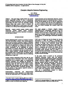
Figure 1 shows three separate processes formed into concurrent processes that collaborate and are context-sensitive. Process 1 (task A) and process 2 (task B) are performed concurrently as indicated by the OpEMCSS language Split Action &dquo;Splitl&dquo; and Assemble Event &dquo;Assemblel&dquo; blocks. When processes 1 and 2 are both complete, process 1 (task C) continues and process 2 ceases to exist. Processes 1 and 2 are related because they solve the same part of the user/ customer problem, and are associated with the same
subsystem (X). During process 3, associated with subsystem (Y), task D is performed before one of the alternative tasks E
or
F.
made
However, the choice between tasks E
F,
1 and 2 state variables that are sent to process 3 by Message Event Action block from process 1. Therefore, process 3 modifies its behavior based on the activities of processes 1 and 2 of subsystem X. Thus, the transition from task D to E or F is contextsensitive. Since process 3 is associated with subsystem Y, ~h15 nanbition implements one form of collaboration between subsystems. Context-free systems are systems in which every transition is based on a context consisting of the state dimensions of a single process. A context-free transition occurs where process 3, task D, is followed by task E, and event Eb depends on only process 3 state variables where (D) -> Eb ( E) is such a rule. In summary, each process shown in Figure 1 represents all alternative sequences of states and events, describing the behavior of a part of the system. States cess
a
Figure 1. Collaborating agents 252
or
by an alternate action block, depends on pro-
Downloaded from http://sim.sagepub.com at PENNSYLVANIA STATE UNIV on April 16, 2008 © 1999 Simulation Councils Inc.. All rights reserved. Not for commercial use or unauthorized distribution.
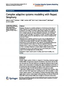
Figure 2.
A
menu
of OpEMCSS
graphical discrete event simulation library blocks
represent periods of time where a task is being executed by a subsystem, or a task is waiting for some logical condition to be true before it can continue. Each process has a discrete state name and zero or more state variable values to model the attributes of subsystems, progress of tasks, or other functional and architectural issues as discussed above. Events represent instantaneous changes in the discrete state or any of the state variables for a process. Because of the split action and assemble event pairs in a system process model (i.e., &dquo;Splitl-Assemblel&dquo; in Figure 1), process instances can come into and out of existence as a function of time. Such variable instantiation of processes is similar to the Object-Modeling Technique (OMT) where instances of object classes are created and deleted as the program executes [10, 11]. 2.2 Overview
of OpEMCSS Library Blocks OpEMCSS blocks are listed in Figure 2 in alphabetical order. These blocks can also be organized by categories : 1.
Begin Event, End Event, and Evolutionary Algorithm blocks that define a system process instance (EXTEND calls these &dquo;runs&dquo;);
2.
Split Action and Assemble Event that define the begin and end of concurrent processes;
3. Global Reaction Time Event, Reaction Time Event, and Wait Until Event that model the time spent in a discrete state; 4. Alternate Action, Context-Sensitive Event Action, Event Action, Global Event Action, Initialize Event Action, Input Event Action, Local Event Action, and Message Event Action that perform event actions ; and
5. Executive Block, that sequences events in simulated time. A brief summary of each library block is provided below. For a more detailed evaluation, Version 4.0 EXTEND users may download the library from
&dquo;http: / /ecs.fullerton.edu/ ~jclymer.&dquo; 2.3
Category1 The Begin Event block generates an initial process instance item and initializes its attributes to start a system process instance, or simulation run. An Evolu-
tionary Algorithm block can be the action of a begin optimal process control parameters. A Split Action block, that creates a set of concurrent processes, usually follows the begin event block event to search for
and its initialization actions. Since each concurrent process instance uses the same initial attributes, these attributes can provide global communication among
Downloaded from http://sim.sagepub.com at PENNSYLVANIA STATE UNIV on April 16, 2008 © 1999 Simulation Councils Inc.. All rights reserved. Not for commercial use or unauthorized distribution.
253
all concurrent processes to manage their context-sensitive interactions. The End Event block deletes the final process instance item of a simulation run. This block can obtain parameter values from up to five blocks, as specified in its dialog. These values are accumulated to produce an average value for each selected parameter based on a sample of simulation runs. The End Event block also sends these parameters to each Evolutionary Algorithm block for computation of population member fitness. 2.4
Category 2 The Split Action and Assemble Event blocks, working in pairs, allow concurrent process instances at the same level in the system process to be synchronized according to a user-supplied logic equation. Split Action and Assemble Event blocks allow a process instance to come into existence and operate concurrently with other process instances for a period of time, ceasing to exist when assemble logic is satisfied.
Split and assemble pairs can be carried to, at most, the third level. For example, &dquo;(split (split (split assemble) assemble) assemble)&dquo; represents three levels. in an object-oriented model of a system, variable numbers of objects come into existence, exist for a time, then go out of existence. An OpEMCSS process diagram is similar to an OMT model in that each OpEMCSS diagram can define a variable number of process instances. This contrasts with basic timed Petri-net models that require a diagram to be duplicated for each process instance; however, some enhanced Petri nets use colored tokens that may allow multiple process instances to be modeled by the same diagram. When concurrent processes are synchronized, Split Action and Assemble Event blocks work together to ensure all process instances involved are deleted. This complex programming detail is performed automatically by these blocks. It is complex because these blocks may be managing many instances of concurrent processes at different levels of split and assemble. 2.5
Category 3 Category 3 models time required for a perform a task or wait for a logical condi-
Each block in
process
to
tion to be satisfied to continue. For the Global Reaction Time Event block, reaction time is computed by an equation. The reaction time equation can be a function of GAMMADELAY, a Gamma-distributed random variable, plus up to four attributes specified in the block dialog. Within the Global Reaction Time Event block, up to two global attributes can be modified. Global attributes represent information shared by all process instance items in the model. The &dquo;+=&dquo; operation is available to perform this modification. For example, when a shared resource is allocated to a process instance, the 254
attribute R, representing the quantity of this resource, decremented. The operation R += -1 decrements R globally so all process instances that share this resource are notified. In this case, the += operamust be
tion is
equivalent to R
=
R - 1.
The Reaction Time Event block has a Gamma-distributed reaction time specified in the block dialog. Event actions permitted are modifications of up to
global process instance item attributes, using the &dquo;+=&dquo; operation, and one local process instance item attribute based on an equation. The Wait Until Event block can have its time duration determined by a logical equation. The wait until two
logic equation can be a function of up to eight process instance attributes, specified in the block dialog, plus built-in parameters to achieve pre-emptive, priority allocation. Event actions allowed in the block modifications of up to two global process instance item attributes using a &dquo;+=&dquo; operation. A process instance item arriving on the &dquo;Direct&dquo; input connector of the Wait Until Event block bypasses the logic equation and is sent directly to the output connector. Direct input allows a &dquo;passivated&dquo; wait event to be modeled. Such a process waits until another process &dquo;;v~akes it up&dquo; with direct execution. The Global Reaction Time Event block works with the Wait Until Event block to achieve pre-emptive, priority resource allocation. Details of how to accomplish this are given in the &dquo;help&dquo; section of each block’s dialog. The Executive and Wait Until Event blocks work together to ensure that any time a global state variable is changed anywhere in the model, all wait logic is checked again before time is advanced. This ensures that no improper wait time is accumulated. resource
are
2.6
Category 4
Blocks in this category perform an event action after a Category 3 event block is completed. The process state represented by an event block allows a process instance to model a time period, such as when the process performs a task or waits for a logical condition to become true. Each event block maintains a linked list, ordered by time, to store process instance items currently associated with the state represented by the block. When an event occurs, a process instance item is sent from an event block and passes through zero or more action blocks to the next event block. Event blocks have only a limited capability to perform event actions; action blocks expand the kinds of event actions that can be performed when an event occurs. Alternate Action blocks allow one of three alternate transition paths to be selected, after an event has occurred, based on a decision equation. The DECISION value can equal 1, 2, or 3, which specifies the top, middle, or bottom output connector of the block, respectively. The decision equation can be a function of
Downloaded from http://sim.sagepub.com at PENNSYLVANIA STATE UNIV on April 16, 2008 © 1999 Simulation Councils Inc.. All rights reserved. Not for commercial use or unauthorized distribution.
eight attributes, specified in the block dialog, a uniformly distributed random &dquo;RandomNum,&dquo; plus number, or &dquo;CurrentTime.&dquo; up to
Context-Sensitive Event Action blocks search a set of process instance items, as specified by a process identifier, and return a value for AttributeOut based on an equation. The search can employ up to four global attributes, from each process instance item of the set searched, and up to four local attributes from the process instance item passing through the block. It may also use &dquo;RandomNum,&dquo; a uniformly distributed random number, or &dquo;CurrentTime.&dquo; Context-Sensitive Event Action blocks allow process transitions to be based on state dimensions of a set of processes. An Event Action block can modify two global process instance attributes, using the &dquo;+=&dquo; operation, and one local process instance item based on an equation. The equation can be a function of up to four attributes, specified in the block dialog, plus &dquo;RandomNum,&dquo; a uniformly distributed random number, or &dquo;CurrentTime.&dquo; A new process instance item can be created by an Event Action block and sent to the input connector of a reaction time or wait until event block. This feature can represent a generator process that creates new process instance items as a function of time. For example, arrival of jobs into the system during a period of time can be modeled. This feature can also allow one process instance to execute another process instance directly. For example, a &dquo;passivated&dquo; process can be &dquo;waked up&dquo; by direct execution as discussed for the Wait Until Event block. Direct execution of events makes many types of complex, context-sensitive transitions possible. A Global Event Action block can modify two global attributes based on an equation. Each global process instance attribute, having the proper process number, is modified by an attribute equation that can be a function of up to eight process attributes, specified in the block dialog, plus &dquo;RandomNum,&dquo; a uniformly distributed random number, or &dquo;CurrentTime.&dquo; If process number is zero, all system process instance items are modified. Otherwise, only process instance items with &dquo;Process,&dquo; an element of the process identifier equal to process number, are modified. If the &dquo;local&dquo; box is checked in the dialog, the process instance item passing through the block is also updated. An Initialize Event Action block initializes up to 16 process instance attributes specified in the dialog. This block allows only local attributes of process instance items passing through the block to be initialized. A Begin Event block of Category 1 initializes attributes global to all system processes. An Initialize Event Action block can expand the number of attributes a Begin Event block initializes. An Input Event Action block can modify up to five local process attributes based on a database of values read from a file at the beginning of a set of simulation
The database is a two-dimensional array that be indexed by an attribute value or a constant value. Row and column values for each attribute modified are specified in the block dialog. A Local Event Action block is similar to the Global Event Action block, but only attributes of the process instance item passing through the block are modified. If &dquo;Accumulate&dquo; is set to true in the block dialog, the block accumulates process instance items (deletes them) passing through the block until the last one is received, which is sent to the output connector. Thus process instance items created by a generator process that complete their state-event sequence can depart rather than being stored in an Assemble Event block. This allows the model to run much faster if many processes are created. A Message Event Action block is similar to the Context-Sensitive Event Action block. Both allow processes to share information. The Message Event Action block uses an equation, based on up to four local and four global attributes as specified in the block dialog, to decide which process instances shall receive from one to four messages specified in the block dialog. The Message Event Action block simulates message passing from one subsystem to another. A process identifier narrows the search, similar to the Context-Sensitive Event Action block. A Message Event Action block allows information to be sent to each selected process instance when the sending process is ready. The Context-Sensitive Event Action block allows information to be obtained by the receiving process when it is ready. Thus, the Message Event Action block working with the Context-Sensitive Event Action block can simulate various communication protocols in a network of subsystems. runs. can
2.7
Category 5 An OpEMCSS Executive block sequences events in simulated time. A Context-Sensitive Priority Block computes a priority for each process instance item at each discrete time based on an equation and prints process identifier, discrete state, and state variable values for each process instance at the end of each discrete time. The Executive and Context-Sensitive Priority Block work together to print a state trace each time simulated time is updated.
Summary of OpEMCSS Block Categories An important feature of the OpEMCCS graphical simulation language is that a process diagram can de2.8
process instances without having to duplicate the process diagram for each one. This is especially important when modeling systems where the number of an object is variable. For example, the number of elevators in the elevator model could be changed from two to four or more without changing the process diagram. scribe
one or more
Downloaded from http://sim.sagepub.com at PENNSYLVANIA STATE UNIV on April 16, 2008 © 1999 Simulation Councils Inc.. All rights reserved. Not for commercial use or unauthorized distribution.
255
This is possible because the reaction time and Wait Until Event blocks of Category 3 can keep track of as many process instances as computer memory permits. The Split Action block of Category 2 can generate a variable number of process instances, and the Assemble Event, also of Category 2, can synchronize these process instances using a wide range of logical expressions.
3.
to control process .
At each stage of system design and development, it is necessary to evaluate the proposed design in terms of system requirements. At first, Discrete Event Simulation (DES) is used to evaluate the design. Next, combined continuous and DES with hardware/software/ man-in-the-loop techniques are used to evaluate prototype subsystems within a simulated system environment. Finally, system integration occurs and the complete system is subjected to a rigorous test and evaluation procedure to verify and validate all requirements. Simulation may continue during production and product use to evaluate enhancements or effects of changes occurring in the system operating environ-
Simulation-Based
Systems Engineering beginning of the design process, OpEMCSS system design methodology is based on expansionism, then shifts to reductionism. Once an optimal system concept has been developed using expansionist methodology, reductionism is applied to reduce the system to a subsystem hierarchy to facilitate hardware-software design and project management. ~
~
follows.
Analysis: system is reduced to a hierarchy of simple subsystems; Mechanistic: each subsystem transforms inputs into
~
as
ment.
outputs; and
System theory:
in
understands system in terms of in-
dividual behaviors of its nections.
~
subsystems and their con-
~
~
in terms of its interactions and context task flow and mechanism; and
cess as
as
design as a function of mission attribute valalternative designs. DI values are averages based on a sufficient sample size of simulation tem
ues or
runs ~
well
System theory: understands emergent system behavior in terms of process collaboration. A system can be reduced to independently operating subsystems, but we cannot analyze each subsystem independently and then integrate analysis results to understand the system as a whole. This is because collaborating subsystems transform each other, producing a much more complex system behavior than possessed by any single subsystem. Once a top-level concept of the whole system has been developed using the expansionist system design methodology, the system concept is reduced to a subsystem hierarchy suitable for hardware and software ~
engineering. Collaboration among to achieve than
mere
subsystems is more difficult
coordination; therefore, bringing
such
complex systems into being requires a systems engineering methodology [2, 12] that uses discrete event simulation based on CSS theory: First, use Operational Evaluation Modeling (OPEM) Context-Sensitive System (CSS) graphical discrete event simulation library (OpEMCSS) to design each system process to work optimally to perform its activities; Second, determine the knowledge and decision ~
~
rules each process 256
requires to make local decisions
Computer simulations produce two types of results support of the systems engineering process: Sensitivity analysis provides Design Information (DI) about performance and efficiency of the sys-
’
Expansionism is characterized as: Synthesis: a system is a network of subsystems described in terms of communicating processes; Context-sensitive: explains behavior of each pro-
multi-process
define subsystem coordination and communication methods required for effective subsystem connection and sharing of essential information.
At the
Reductionism is characterized
behavior and for
collaboration; and Third, allocate system processes to subsystems and
necessary for convergence.
Process
analysis provides insight into interactions among parallel processes that degrade either performance or efficiency. Process analysis is performed using detailed event-
state traces for
include
an
a
simulation
run.
An event trace
can
output for each block involved in a transi-
tion. A state trace includes a process identifier plus process attribute values and discrete state for each process instance currently in existence.
4.
Context-Sensitive
Building Elevator System
blocks work
OpEMCSS together to simulate a complex adaptive system. Figure 3 shows a directed graph model of a building elevator system. Shown are three concurrent processes: (1) PERSON ARRIVAL PROCESS, (2) PERSON PROCESS, and (3) ELEVATOR MOTION PROCESS. How OpEMCSS blocks work together to simulate these building elevator system processes is discussed next. The section concludes with an evaluation of CAS versus non-CAS building elevator system performance. 4.1 Person Arrival Process
Each PERSON ARRIVAL PROCESS instance is a generator process that models arrival of people on a particular floor of a building to use one of its elevators. This process is duplicated by the Split Action block &dquo;Split&dquo; to provide a person inter-arrival process instance for each floor of the building.
Downloaded from http://sim.sagepub.com at PENNSYLVANIA STATE UNIV on April 16, 2008 © 1999 Simulation Councils Inc.. All rights reserved. Not for commercial use or unauthorized distribution.
Figure 3.
A directed
graph model of a building elevator system
The &dquo;Person Arrival&dquo; state models inter-arrival using a Global Reaction Time Event block. This block permits inter-arrival time to be a function of floor number. Three Local Event Action blocks are used to set values for local attributes &dquo;DestFloor,&dquo; &dquo;MyDir,&dquo; &dquo;ElvNumber,&dquo; &dquo;CallFloor,&dquo; and &dquo;CallButton.&dquo; Attribute &dquo;CallButton&dquo; is a code indicating call floor and desired direction of travel. This attribute is included to implement the elevator collaboration decision rule. Next, an Event Action block increments a global attribute &dquo;CallElevator&dquo; used in the wait logic of ELEVATOR MOTION PROCESS &dquo;Elv Wt for Call&dquo; state. A PERSON PROCESS instance item is created by the Event Action block and sent to the initial Wait Until Event block of PERSON PROCESS where the person waits for an elevator. All local attributes of PERSON ARRIVAL PROCESS are passed to the new PERSON PROCESS instance. Finally, an Alternate Action block determines whether to schedule another person arrival or a transition of the PERSON ARRIVAL PROCESS to the Assemble Event block &dquo;Assemble&dquo; where all processes are synchronized to end the simulation run. time
4.2 Person Process
The PERSON PROCESS models a person waiting to board an elevator, boarding an elevator, waiting to reach a destination floor, and departing the elevator. It is duplicated for each person in the building elevator system. Note the person arrival process appears only once, though there is an arrival process for every floor of the building. Thus the number of floors can be variable. Of the two Wait Until Event blocks defining the process, the one on the left has two inputs. The input marked &dquo;Person&dquo; receives a new process instance item from PERSON ARRIVAL PROCESS as discussed above. The other input comes from the Split Action block &dquo;Split&dquo; and does not receive items. However, language syntax requires this input to be present as shown. The state represented by the first Wait Until Event block is &dquo;Person Wt Elv.&dquo; To exit this wait state, logic requires an elevator at the person’s call floor, with its door open, and moving in the direction desired. When a person boards an elevator, a Local Event Action block sets the value of attribute &dquo;ElvNumber&dquo; to the number of the elevator the person has boarded.
Downloaded from http://sim.sagepub.com at PENNSYLVANIA STATE UNIV on April 16, 2008 © 1999 Simulation Councils Inc.. All rights reserved. Not for commercial use or unauthorized distribution.
257
The ELEVATOR MOTION PROCESS uses this attribute to determine if a person has boarded an elevator. The process state becomes &dquo;Wait Elv Dst,&dquo; which represents the time a person is on board the elevator waiting for the elevator to reach the destination floor and open its door. After a person departs the elevator, a Global Event Action block counts the number of persons who have departed the elevator and computes system throughput in persons per hour. PERSON PROCESS instances are accumulated by a Local Event Action block such that the last instance is sent to the Assemble Event block &dquo;Assemble&dquo; to synchronize all concurrent processes to end a simulation run. 4.3 Elevator Motion Process ELEVATOR MOTION PROCESS models elevator operation. Note that a single elevator process on the diagram represents any number of elevators. Thus design studies can be performed to determine the optimal number of elevators using the same diagram, though event actions may have to be changed. An elevator waits for a call to a floor. When a call arrives, the elevator moves to the call floor and opens its door. Zero or more persons board the elevator. If one or more persons board the elevator, it moves toward its ultimate destination floor. However, it may stop to let people on or off at floors on the way. Each time an elevator stops, it opens its door. If no one boards an elevator at a call floor, the elevator stops there and waits. A Wait Until Event block represents an elevator waiting for a call. This wait block has three inputs as shown. The middle input comes from the Split Action block &dquo;Split.&dquo; The split block duplicates ELEVATOR MOTION PROCESS to represent each of the two elevators in the building. A Local Event Action block on the input from the split block initializes a local variable &dquo;ElvFloor&dquo; to begin a simulation run. If global attribute &dquo;CallElevator,&dquo; incremented by PERSON ARRIVAL PROCESS, is greater than zero, the processinstance makes the transition out of wait-state &dquo;Elv Wt for Call.&dquo; A Context-Sensitive Event Action block searches the set of all instances of PERSON PROCESS. This search locates each person who has called an elevator, has not yet boarded an elevator (ElvNumber is zero), and for whom the call is not being answered by the other elevator. The search finds the call that is the closest to where the elevator is now, though other search strategies are possible. If the search finds no call that satisfies this logic, the Alternate Event Action block returns the process to the &dquo;Elv Wt for Call&dquo; state. If a proper call is found, ELEVATOR MOTION PROCESS makes the transition to the &dquo;Mv to Call Flr&dquo; state represented by a Global Reaction Time Event block. Reaction time is a function of distance to the call floor. A Local Event Action block computes a local
258
attribute &dquo;ElvFloor&dquo;, and a Global Event Action sets global attributes &dquo;ElvlFloor&dquo; or &dquo;Elv2Floor&dquo; to their proper values. PERSON PROCESS evaluates these global attributes to determine when a person can board an elevator. ELEVATOR MOTION PROCESS state next changes to &dquo;Elv Door Open,&dquo; represented by a Reaction Time Event block where reaction time is determined from a gamma distribution. When an elevator door opens, a person may board. The next block in ELEVATOR MOTION PROCESS is an Event Occurrence block. This block allows action blocks to be shared by two alternative process paths, as shown in Figure 3, to simplify simulation. Action blocks after the Event Occurrence block determine ultimate destination floor and direction of travel. If one or more persons have boarded the elevator, ELEVATOR MOTION PROCESS changes to &dquo;Mv Elv one Flr&dquo; state, represented by a Reaction Time Event block, where reaction time is obtained from a gamma distribution. Otherwise, the process returns to &dquo;Elv Wt for Call&dquo; state. A search of PERSON PROCESS instances is performed by a Context-Sensitive Event Action block to determine if anyone on board the elevator needs to depart, or if anyone is waiting for a call (direction of elevator travel correct) needs to board. A local attribute &dquo;Stop&dquo; is set to &dquo;1&dquo; if the elevator must stop. If attribute &dquo;Stop&dquo; is &dquo;1 &dquo;, reaction time of the &dquo;Elv Door Open&dquo; state, modeled by a Global Reaction Time Event block, is 10 seconds. Else, reaction time is zero and the door remains closed. If the ultimate destination has not been reached, an Alternate Action block executes a transition back to &dquo;Mv Elv one Flr&dquo; state. If the ultimate destination has been reached, a Context-Sensitive Action block examines all instances of PERSON PROCESS to determine if someone is still in the elevator. This can occur if someone boarded the elevator while it was moving toward its ultimate destination. If someone is still there, the next Alternate Action block transitions to determine a new ultimate destination and direction. Otherwise, a transition is made back to &dquo;Elv Wt for Call&dquo; state.
of Elevator Performance The elevator system in the engineering building at California State University, Fullerton was the subject 4.4 Evaluation
for the model discussed above. In this system, if both elevators are idle and one is called, both elevators come. This indicates the elevators do not collaborate. Is there a strategy that reduces user waiting time? The elevator model was run two ways. First, elevators are operated independently (attribute CAS equals zero). Second, elevators collaborate so only one elevator answers a call (attribute CAS equals one). A unique call occurs for each combination of call floor and desired direction. In both cases, if two or more calls are present, the elevator answers the nearest call.
Downloaded from http://sim.sagepub.com at PENNSYLVANIA STATE UNIV on April 16, 2008 © 1999 Simulation Councils Inc.. All rights reserved. Not for commercial use or unauthorized distribution.
required that assists visualizing, understanding, and designing CSS transitions necessary for self-organization and desired emergent behavior at the &dquo;edge of
Figure 4.
Evaluation of elevator
system performance
Other calls are answered as the elevator moves toward its destination floor. This strategy reduces time required for an elevator to move to a call floor. Other strategies are possible in the model. If elevators operate independently and both are waiting for a call, both answer the call. Usually a person boards the elevator that arrives first, leaving the other elevator empty. The empty elevator returns to wait for a call. Figure 4 shows average time a person waits for an elevator as a function of person inter-arrival time. When elevators operate independently, minimum waiting time is about 30 seconds-the time it takes an elevator to move three floors. Elevator collaboration reduces minimum person-waiting time by one-half. Elevators are not likely to be idle at the same time when demand for elevator services is high, so elevators do not have an opportunity to answer the same call. The difference in maximum waiting times between CAS and non-CAS is greatly reduced when there is little opportunity for collaboration. Therefore, as opportunity for collaboration occurs more frequently, elevator performance can be improved through collaboration.
Summary and Conclusions Complex Adaptive Systems are systems in which subsystems share knowledge and each subsystem adapts 5.
its behavior to optimize effectiveness within a local network. If local networks overlap and proper decision rules are used, feedback loops can result that optimize global system effectiveness. However, if degree of overlap or coupling between local networks is too small, self-organization and the desired emergent be-
havior cannot occur. Excessive coupling leads to chaotic system behavior. Degree of coupling must be balanced at the &dquo;edge of chaos&dquo; to achieve the behavior desired for the entire
system [2-7]. A graphical modeling language is
chaos.&dquo; It has been argued in this paper that context-sensitive systems theory, a generalization of finite state machines is useful for visualizing, understanding, and designing CAS. The OpEMCSS graphical discrete event simulation library explicitly represents CSS transitions required for CAS. An expansionist systems engineering methodology that employs the OpEMCSS library was discussed. A multi-elevator system was presented to demonstrate application of the methodology and OpEMCSS library. It was shown that the same diagram could model a variable number of elevators and building floors. Each elevator shares knowledge with the other to reduce the time people wait for service. The Operational Evaluation Modeling (OpEM) graphical discrete event simulation language [12, 13] was developed to describe the context-sensitive transitions required for CAS interactions. The challenge in developing the graphical version of this language was to apply lessons learned from experience obtained from the OpEM Pascal Simulation programming system [2,12-19] used during the past 15 years. This system, though flexible in terms of data structures and event action code that can be created, is not easy to
program.
major challenge, for which experience with OpEM Pascal simulation was applied, is in determining a primary set of event action blocks sufficient to model any system of interest efficiently. To solve this problem, OpEMCSS event action blocks were developed to provide the capability necessary to model a set of benchmark models. When the number of benchA
mark models increases, other event action blocks may be needed. See web site &dquo;http//ecs.fullerton.edu/ ~jclymer/&dquo; to download the OpEMCSS library and benchmark models. The EXTEND simulation programming system, the foundation upon which OpEMCSS is built, provides an excellent (and inexpensive) platform from which a more sophisticated simulation language can be developed. It is a relatively high-level language to begin with and already provides the capability for graphical interaction. Its proprietary C-like language makes it very flexible, and creation of new types of blocks rela-
tively easy. We believe the relatively low cost and great flexibility of EXTEND, made more capable by the addition of the OpEMCSS library, will attract users who can share ideas and create new blocks that will improve CAS modeling. It is hoped a community interested in CAS will form that chooses OpEMCSS as its modeling tool. A common modeling language is well known to improve exchange of ideas within a research community. The OpEMCSS library itself is easily extended to
Downloaded from http://sim.sagepub.com at PENNSYLVANIA STATE UNIV on April 16, 2008 © 1999 Simulation Councils Inc.. All rights reserved. Not for commercial use or unauthorized distribution.
259
include new blocks; thus the OpEMCSS library can evolve as the research community learns more about CAS. Some expansions of the OpEMCSS library, to be discussed in subsequent papers, are as follows. ~
Subsystem motion blocks have been added to OpEMCSS such that each subsystem can be located three-dimensional (X, Y, Z) space. Each subsystem can be associated with a collection of process instances, and it can move in the space relative to other subsystems. When one subsystem comes within a specified range (or angle) of another, a process instance can be notified. This process instance can execute an appropriate response for the subsystem. The subsystem motion blocks allow continuous motion and subsystem interaction to occur based on discrete events. This is much faster than a time-step model of motion. in
~
a
A &dquo;Classifier Event Action block&dquo; has been added to the library such that each block has process state variables as inputs. This block generates an output based on fuzzy sets and fuzzy rules, and allows process decision making to evolve, discovering the most effective rules to control the system.
Besides research and engineering development of Complex Adaptive Systems, OpEMCSS provides a means to teach engineering, business, and science students about CAS. Using a set of benchmark models, a common set of CAS experiments can be devised to illustrate basic principles of CAS. New blocks and additional benchmark models can assist directly in teaching the next generation of engineers, business
[11]Rumbaugh, J., et al. Object-oriented Modeling and Design, Prentice-Hall, Englewood Cliffs, NJ, 1991.
[12] Clymer, J.R. Systems Analysis Using Simulation and Markov Models, Prentice-Hall, Englewood Cliffs, NJ, 1990. [13] Clymer, J.R., Corey, P.D., Nili, N. "Operational Evaluation
Modeling." SIMULATION, Vol. 66, No. 6, pp 261-270, December 1990.
[14] Clymer, J.R. "System Design Using OpEM Inductive/Adaptive Expert System Controller." IASTED International journal
of Modeling Simulation, Vol. 10, No. 4, pp 129-136, 1990. & [15] Clymer, J.R., Corey, P.D., and Gardner, J. "Discrete Event Fuzzy Airport Control." IEEE Transactions on Systems, Man, Cybernetics, Vol. 22, No. 2, pp 343-351, March-April 1992. [16] Clymer, J.R., Cheng, D.J., Hernandez, D. "Induction of Decision Making Rules for Context Sensitive Systems." SIMULATION, Vol. 59, No. 3, pp 198-206, September 1992. [17] Clymer, J.R., Corey, P.D., Bandukwala, H. "Induction of Classification Rules for a Sonar System." SIMULATION, Vol. 62, No. 4, pp 256-267, April 1994. [18] Clymer, J.R. "Induction of Fuzzy Rules for Air Traffic Control." Proceedings-1995 IEEE International Conference on Systems, Man, and Cybernetics, Vancouver, British Columbia, and
Canada, pp 1495-1502, October 22-25, 1995. [19] Corey, P.D., Clymer, J.R. "Discrete Event Simulation of Object Movement and Interactions." SIMULATION, Vol. 56, No. 3, pp 167-174, March 1991.
7. Additional Reading Axelrod, R.M. The Evolution of Cooperation, New York,
Basic Books, Inc., 1984. Blanchard, B.S. and Fabrycky, W.J. Systems Engineering and Analysis, Third Edition, Prentice-Hall, Inc, Englewood Cliffs, NJ, 1998.
John R. Clymer is a Professor of Electrical Engineering at California State University Fullerton (CSUF) and consults in the area of systems engineering, simulation, and artificial intelligence. In addition to consulting, he presents intensive short courses at various locations around the United States and abroad. His teaching assignments have included
persons, and scientists about CAS. 6. References [1] Maier, M.W. "On Architecting and Intelligent Transport Systems." IEEE Transactions on Aerospace and Electronic Vol. 33, No. 2, pp 610-625, April 1997.
Systems,
[2] Clymer, J.R. "Expansionist/Context-Sensitive Methodology:
[3] [4] [5] [6]
Engineering of Complex Adaptive Systems." IEEE Transactions on Aerospace and Electronic Systems, Vol. 33, No. 2, pp 686-695, April 1997. Capra, F. The Web of Life, Bantam Doubleday Dell Publishing Group, New York, 1996. Epstein, J.M., Axtell, R. Growing Artificial Societies: Social Science from the Bottom Up, MIT Press, Cambridge, MA, 1996. Holland, J.H. Hidden Order: How Adaptation Builds Complexity, Addison-Wesley, Reading, MA, 1995. Kauffman, S. At Home in the Universe: The Search for the Laws of Self-Organization and Complexity, Oxford University Press, New
computer engineering, system control, continuous systems simulation,
operational analysis and DES simulation, optimization and mathematical programming, and artificial intelligence (fuzzy logic and control, neural networks, and expert systems). Dr. Clymer’s current research interests are focused in the area of intelligent, complex adaptive systems, applying integrated simulation, artificial intelligence, and evolutionary programming methods to study such systems. He is a founding member of the Applied Research Center for Systems Science at CSUF. He is
a
INCOSE.
York, 1995.
[7] Kelly, K. Out of Control: The New Biology of Machines, Social Systems, and the Economic World, Addison-Wesley, Menlo Park, CA, 1994.
[8] Pritsker, A.A.B. Introduction
to Simulation and SLAM
II, John
Wiley and Sons, New York, 1986. [9] Yeh, R. T. Applied Computation Theory: Analysis, Design, and Modeling, Prentice-Hall, Englewood Cliffs, NJ, 1976. [10] Oliver, D.W. "Engineering of Complex Systems with Models." IEEE Transactions on Aerospace and Electronic Systems, Vol. 33, No. 2, pp 667-685, April 1997.
260
Downloaded from http://sim.sagepub.com at PENNSYLVANIA STATE UNIV on April 16, 2008 © 1999 Simulation Councils Inc.. All rights reserved. Not for commercial use or unauthorized distribution.
member of IEEE, SCS, and


![Complex Adaptive Systems [PDF]](https://m.moam.info/img/260x300/complex-adaptive-systems-pdf_647afa97098a9e24468b45ae.jpg)