use vrj , vdi to denote the noises in the j-th relay and the i-th ..... Huawei Research Grant; Shanghai Innovation Key Project. (08511500400). REFERENCES.
Complex Field Network Coding for Wireless Cooperative Multicast Flows Jun Li, Wen Chen, and Xinbing Wang Department of Electronic Engineering, Shanghai Jiaotong University, Shanghai, China. 200240. Email: {jleesr80, wenchen, xwang8}@sjtu.edu.cn Abstract—Network coding is a promising technology designed to reach the Min-cut Max-flow capacity in wired network. While in wireless cooperative environments, it has been proved that network coding can also increase the system throughput by taking the advantage of the broadcast nature of electromagnetic waves. In this paper, we establish a 2-source and 2-destination cooperative systems with arbitrary number of relays (2 − N − 2 system), and then the designed signal-superposition-and-forward based complex field network coding protocol (SiSF-CFNC) is applied to the model. We define the system frame error probability (SFEP) to measure the performance of cooperative multicast systems with the proposed protocol. Power allocation schemes as well as precoder design are concentratively studied to improve the system performance without cutting down the system throughput.
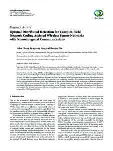
I. I NTRODUCTION Network coding has been proved to reach the network multicast capacity bound in the wired systems [1]. Since network coding can enhance network throughput, there have a lot of researches on different coding approaches [2], [3], [4]. Recently, how to leverage network coding in wireless physical layer networks for system capacity improvement has drawn increasing interest [5]-[11]. We take the two sources, one relay and two destinations (2 − 1 − 2) cooperative multicast network [12] for example. In the multicast network shown as Fig. 1, we suppose that s1 as well as s2 broadcast their information to the two destinations d1 and d2 simultaneously. All nodes are in half-duplex mode. From Fig. 1, we can see d1 (or d2 ) is out of the transmission range of s2 (or s1 ). The shared relay can help s1 and s2 reach their destinations. There are two transmission schemes. The first sheme is through the traditional way without network coding, which occupies four time slots: 1. s1 → {r, d1 } with information Is1 ; 2. r → d2 with information Is1 ; 3. s2 → {r, d2 } with information Is2 ; 4. r → d1 with information Is2 . The second one is by complex field network coding method that is more effective with two time slots: 1. s1 → {r, d1 } with signal Xs1 , s2 → {r, d2 } with signal Xs2 ; 2. r → {d1 , d2 } with signal f (Xs1 + Xs2 ). Note that in SiSF-CFNC, mixed signals received from both sources are not decoded by the relays. Instead, relays only amplify the signals and retransmit them to the destinations.
.... ..... ...... ..... 1 ... ..............
... ...... ....... ..... .. .........1 ......
s
d
........ .... ..... .... . ...............
r
...... ..... ..... .... 2 .... ..............
s
....... ..... ..... .... ... .........2 .....
d
Fig. 1. A wireless 2 − 1 − 2 multicast system where the circles denote the transmission ranges. Due to the power constraint, s1 (s2 ) should borrow r to transmit messages to d2 (d1 ).
So function f (·) is a linear mapping mechanism. Obviously, the second transmission scheme consumes the least time slots and hence acquires the highest throughput. In this paper, we explore the SiSF-CFNC protocol based on the established cooperative multicast system. Our contributions are as follows: 1) Performance analysis on the proposed protocol: We use the SFEP as the measurement of the SiSF-CFNC protocol based multicast system. SFEP is then deduced and utilized as a metric to execute the system optimization. 2) Power allocation scheme and precoder design: Based on the performance analysis, we conclude that a proper power allocation scheme and proper precoder can improve the performance without increasing the transmission time slots. By the expressions of system FEP of the protocol, we give the power allocation scheme. Precoder is also designed to achieve higher diversity gain. The notations used in this paper go as follows. Bold upperand lower-case letters denote matrices and column vectors respectively. x ˆ represents the decoded symbol of a symbol x. ˆx ˆ are represented the decoded vector and decoded matrix. and X Σn denotes the auto-covariance matrix of the vector n. E(·) is the expectation operation. z(x) , O(y(x)), y(x) > 0 denotes that there exists a positive constants c such that |z(x)| ≤ cy(x) when x is large.
978-1-4244-2324-8/08/$25.00 © 2008 IEEE. This full text paper was peer reviewed at the direction of IEEE Communications Society subject matter experts for publication in the IEEE "GLOBECOM" 2008 proceedings.
s1 xs1 ,1 s2 xs2 ,1
···
xs1 ,2
···
xs2 ,2
r1 xr1 r2 .. . .. . rN
f (xr1 )
d1 xd1 ,1 d2 xd2 ,1
xd1 ,2
xd1 ,3
xd1 ,4
xd2 ,2
xd2 ,3
xd2 ,4
Fig. 2.
xr2
xs1 ,N xs2 ,N
f (xr2 )
xrN f (xrN ) · · · xd ,2N−1 xd ,2N 1 1 · · · xd ,2N−1 xd ,2N 2
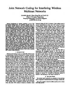
II. S YSTEM M ODEL We setup the 2 − N − 2 (N ≥ 1) multicast cooperative transmission system by using the second NBK non-orthogonal scheduling scheme [13]. Fig. 2 displays the transmission scheme of s1 and s2 . Note that dashed boxes denote the receiving process while the solid ones denote transmitting process. We assume that the system has been well synchronized. From Fig. 2, we can see s1 and s2 each transmits N symbols while d1 and d2 each receives 2N symbols during 2N time slots. We define the 2N time slots as a frame period. Then the original symbols vectors in a frame period are denoted by ps1 = [ps1 ,1 , ps1 ,2 , · · · , ps1 ,N ]T for s1 and ps2 = [ps2 ,1 , ps2 ,2 , · · · , ps2 ,N ]T for s2 where all symbols are equally probable form a constellation set composed of QAM signals with zero means and unit variances. We denote psk ,i as the R-bit column vector of symbol psk ,i which comes from R-order QAM constellation diagram. The symbols vectors to be transmitted in a frame period are derived from the original information after preprocessing and power amplification that are denoted by xs1 = [xs1 ,1 , xs1 ,2 , · · · , xs1 ,N ]T for s1 and xs2 = [xs2 ,1 , xs2 ,2 , · · · , xs2 ,N ]T for s2 . The symbols received in the two destinations are denoted by xd1 = [xd1 ,1 , xd1 ,2 , · · · , xd1 ,2N ]T for d1 and xd2 = [xd2 ,1 , xd2 ,2 , · · · , xd2 ,2N ]T for d2 . Then we define the original frame as ps , [ps1 ,1 , ps2 ,1 , ps1 ,2 , ps2 ,2 , · · · , ps1 ,N , ps2 ,N ]T , and also define the frame to be transmitted as xs , [xs1 ,1 , xs2 ,1 , xs1 ,2 , xs2 ,2 , · · · , xs1 ,N , xs2 ,N ]T . To normalize the power allocation, we denote E as the average total network transmission power over a frame, then ) ( N 1 X |xs ,i |2 = κk E (k = 1, 2), E 2N i=1 k ( ) N 1 X 2 (1) E |f(xri )| = τE, 2N i=1 k=1
~1 r1 .. . .. . rN ~2
- d1 * © h1,1 ©©¢¢¸ ©©h ¢ N,1 A ¢ A ¢ A ¢ ¢A ¢ A ¢ hA ¢H 1,2A HH A hN,2 A HH AU d2 j
2
Frame structure and relaying sequence in NBK scheduling scheme.
2 X
s1 H A HH g1,1 HH A j A g1,N ¢¸ A ¢ A ¢ A¢ ¢A ¢ A ¢g2,1 A ¢ *AU © ¢ ©© © g2,N s2 ¢©
κk + τ = 1 and κ1 , κ2 , τ ≥ 0,
where xsk ,i denotes the i-th symbol of the frame transmitted by the k-th source. xri denotes the mixed symbol received by
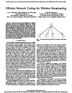
Fig. 3.
Multicast cooperative channels with N relays.
the i-th relay. The channel model is represented in Fig. 3. Each node is constrained by half-duplexing and each relay is isolate from the other relays. All channels are assumed to be flat fading with Rayleigh i.i.d and quasi-static in at least one frame period and all noises observed by relays and destinations are Gaussian distribution. Furthermore, we use ~i , gi,j , hj,i to denote the channels’ coefficients between the i-th source and the i-th destination, the i-th source and the j-th relay, the j-th relay and the i-th destination respectively with zero means and variances σ~2i , σg2i,j , σh2j,i , use vrj , vdi to denote the noises in the j-th relay and the i-th destination with zero means and variances σr2j , σd2i . In the sequel, we assume that σ~2i = 1, σg2i,j = η1 σ~2i , σh2i,j = η2 σ~2i where η1 ,η2 ≥ 1 (i = 1, 2; j = 1, · · · , N ) since these gains may come from strong line-of-sight signals, or may be due to shorter transmission distances. We also assume that the noise variances are same among all the receiver, that is, σr2j = σd2i = σ2 (i = 1, 2; j = 1, · · · , N ). Based on the power constraint in (1), the system SNR is defined as ρ,
E . σ2
(2)
To ease the performance analysis, we further draw another assumptions in the system model: 1. |xsk ,i |2 = |xsk ,j |2 (i, j = 1, · · · , N and i 6= j); 2. |f(xri )|2 = |f(xrj )|2 (i, j = 1, · · · , N and i 6= j). We then turn to the formal expressions of 2−N −2 multicast cooperative channel models with the SiSF-CFNC protocol. Here we only focus on the destination d1 . The same result can be applied to d2 . In SiSF-CFNC protocol, network coding can be seen as the superposition of different signals in the air. So mapping mechanism in the i-th relay is a linear function, that is (3) fi (xs1 ,i , xs2 ,i ) = bi · (g1,i xs1 ,i + g2,i xs2 ,i ), p where bi = 2τE/(2|g1,i |2 κ1 E + 2|g2,i |2 κ2 E + σ 2 ) is the amplification factor for the i-th relay, which is so defined as to balance the system power constraint. For the sake of simplicity, we replace bi with b where b = E(bi ) =
978-1-4244-2324-8/08/$25.00 © 2008 IEEE. This full text paper was peer reviewed at the direction of IEEE Communications Society subject matter experts for publication in the IEEE "GLOBECOM" 2008 proceedings.
p 2τE/(2η1 κ1 E + 2η1 κ2 E + σ 2 ). Then the received signals at the destination are
xd1 ,1 = ~1 xs1 ,1 + vd1 ,1 xd1 ,2 = bh1,1 (g1,1 xs1 ,1 + g2,1 xs2 ,1 + vr1 ) + vd1 ,2 .. . xd1 ,2N−1 = ~1 xs1 ,N + vd1 ,2N−1 xd1 ,2N = bhN,1 (g1,N xs1 ,N + g2,N xs2 ,N + vrN ) + vd1 ,2N . (4)
The transmission model in (4) can be written in a compact matrix form (5) xd1 = X2N h2N + v2N where X2N is a 2N × (2N + 1) matrix, and h2N is a (2N + 1) × 1 column vector, i.e., ⎞ ⎛ xs1 ,1 0 0 ··· 0 0 ⎜ 0 0 0 ⎟ xs1 ,1 xs2 ,1 · · · ⎟ ⎜ ⎜ .. .. ⎟ , .. X2N = ⎜ . . . ⎟ ⎟ ⎜ ⎝xs1 ,N 0 0 ··· 0 0 ⎠ (6) 0 0 0 · · · xs1 ,N xs2 ,N h2N = [~1 , bg1,1 h1,1 , bg2,1 h1,1 , · · · , bg1,N hN,1 , bg2,N hN,1 ]T
and v2N is the 2N × 1 noise vector with v2N ∼ N (0, σ 2 Σv ). v2N and Σv are given by v2N = [vd1 ,1 , bh1,1 vr1 + vd1 ,2 , · · · ,
vd1 ,2N−1 , bhN,1 vrN + vd1 ,2N ]T , ⎞ ⎛ 1 0 ··· 0 0 ⎟ ⎜0 1 + b2 |h1,1 |2 · · · 0 0 (7) ⎟ ⎜ ⎟ ⎜ .. . . .. .. Σv = ⎜ . ⎟. ⎟ ⎜ ⎠ ⎝0 0 ··· 1 0 2 2 0 0 · · · 0 1 + b |hN,1 |
Joint maximum likelihood (ML) decoding is performed at d1 after 2N time slots, (N X ˆs = arg min |xd1 ,2i−1 − ~1 xs1 ,i |2 + p i=1
N X i=1
|xd1 ,2i − bhi,1 (g1,i xs1 ,i + g2,i xs2 ,i )|2
)
(8)
.
III. S YSTEM F RAME E RROR P ROBABILITY FOR S I SF-CFNC P ROTOCOL We introduce the SiSF-CFNC protocol to the established cooperative multicast system. And we measure the performance of the protocol by choosing the frame error probability (FEP) as the criterion. We define that a frame is successfully transmitted if and only if (iff) both destinations can successfully receive the frame. So the FEP of the multicast network can be calculated as Psys = Pd1 (1 − Pd2 ) + Pd2 (1 − Pd1 ) + Pd1 Pd2 ,
(9)
where Psys is the FEP of the whole system. Pd1 and Pd2 are the FEP of d1 and d2 respectively. Since d1 and d2 are symmetrical in the network, the theoretic result of Pd1 and Pd2 are equivalent. There is another criterion of system performance, i.e., pairwise error rate (PEP). For total 22RN codewords, the relationship between FEP and PEP satisfies FEP = 22RN PEP where R is the number of bits in each symbol. To get the FEP formulations, we should first deduce the PEP of each destination. In the sequel, we pick out d1 for more in-depth analysis. To deduce Pd1 , we then should first get PP E,d1 , the PEP of d1 . According to [14], PP E,d1 ¶¾ ½ µ Z π −1 H 1 2 hH 2N U2N Σv U2N h2N = Eh2N exp −ρ dθ, π 0 8 sin2 θ (10) where U2N is the normalized pairwise error matrix, i.e., ´ 1 ³ ˆ 2N X2N − X U2N = √ ⎞ ⎛E us1 ,1 0 0 ··· 0 0 ⎜ 0 0 0 ⎟ us1 ,1 us2 ,1 · · · ⎟ ⎜ ⎜ .. .. ⎟ . . .. =⎜ . ⎟ . ⎟ ⎜ ⎝us1 ,N 0 0 ··· 0 0 ⎠ 0 0 0 · · · us1 ,N us2 ,N (11) The PP E,d1 is given by the following theorem. Q PN 2 N 2 + Theorem 1: Suppose that i=1 |us1 ,i | i=1 (|us1 ,i | 2 |us2 ,i | ) 6= 0. Then when ρ → ∞, the average PEP of d1 for the SiSF-CFNC protocol is (2N + 1)!!2(2N+1) b−2N (η1 η2 )−N ρ−(N+1) lnN ρ + N N P Q 2 2 2 (N + 1)! |us1 ,i | (|us1 ,i | + |us2 ,i | ) i=1 i=1 ¯ µ ¶¯ ⎞ ⎛¯ N ¡ ¢ ¯ ¯ln Q |us ,i |2 + |us ,i |2 ¯ ρ−(N+1) ln(N−1) ρ 1 2 ¯ ¯ ⎟ ⎜ i=1 ⎟. O⎜ ⎠ ⎝ N N P Q |us1 ,i |2 (|us1 ,i |2 + |us2 ,i |2 ) PP E,d1 =
i=1
i=1
(12)
where (2N + 1)!! = 1 · 3 · 5 · · · (2N + 1). We can get the proof by developing the method in [14]. With the PEP formulation given by Theorem 1, we can write the FEP of d1 as Pd1 = 22RN × PP E,d1 . For the symmetrical consideration, it is easy to get Pd2 . By further applying (9), we then get the FEP of whole system. IV. P ERFORMANCE A NALYSIS AND I MPROVEMENTS According to the FEP of the protocol, we go on with the detailed performance analysis. We first throw light on the effect of FEP performance imposed by power allocation and channel gain. To enhance the performance, we then propose the precode method to achieve full diversity gain in the multicast system.
978-1-4244-2324-8/08/$25.00 © 2008 IEEE. This full text paper was peer reviewed at the direction of IEEE Communications Society subject matter experts for publication in the IEEE "GLOBECOM" 2008 proceedings.
p ... 2Eκ/N ps.. 1 u *u HH ...... xs ,i ©© 1 .. . © . .... © ... 6 6 6 .... HH ...© ... HH αi2N−2 · · · · · · 1 © ... j H u b(g . © 1,i xs1 ,i + g2,i xs2 ,i ) * HH...... © α2N−1 © i · · · · · · αi .. © . .... HH © ? ? ...© p ? ... ... HH ... xs ,i © 2Eκ/N ps2 u © ...... 2 j H -u
0
System Frame Error Probability
10
SNR=30dB SNR=40dB SNR=50dB
−1
10
...
Fig. 5.
The precode scheme for the i-th symbol in SiSF-CFNC protocol.
0
10
without precoder with precoder
−2
10
5
10
15
20
25
30
35
Power Allocation
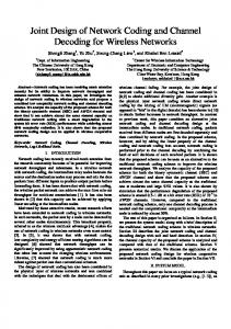
Fig. 4. Relationship between system frame error probability and power allocation for the SiSF-CFNC protocol in 16-QAM modulation with the channel gains η1 = η2 = 1. The number of relays is N = 4. We define x (κ1 + κ2 ) = 31 where x is the value of the abscissa axis, and then x τ = 1 − 31 .
System Frame Error Probability
−1
0
10
−2
10
−3
10
−4
10
A. Power Allocation System performance is relatively sensitive to the power partition and channel gain. We denote relationship between a transmitted frame and its corresponding original frame E allocation matrix as xs =√ Eps , where √ √ is the power √ √ and E = Ediag( 2κ1 , 2κ2 , · · · , 2κ1 , 2κ2 ). From the symmetry of Psys ’s expression, the transmission power of the two sources should be equal to approach the minimum value of Psys . In the sequel, we make κ1 = κ2 = κ, and try to find out the relationship between κ and τ that achieve the minimum value of Psys . We turn to the FEP expressions of SySF-CFNC protocol, and rewrite the symbol error values as E(|usk ,i |2 ) = κE(|μsk ,i |2 ) = κμ,
(13)
where μsk ,i represent the decoded error values of the symbol psk ,i . So when ρ is large enough, we get Psys of the protocol as KSiNC · ρ−(N+1) lnN ρ , (14) E(Psys,SiNC ) = Nκμ · (τμ)N
where K with different subscripts denote the constants to the power allocation factors. From (14), we note that to minimize E(Psys ), we should 1. select suitable κ and τ under the constraint of (1); 2. enlarge the values of μ as far as can. We then concentrate on the first item and remain the second one to the next subsection where we take the advantage of precoder design to enlarge the symbol error values. We first consider the case that all channel gains are equal, i.e., η1 = η2 = 1. We should find out the suitable value of κ and τ which maximize κ · (τ)N . Obviously, when τ = N/(N + 1), E(Psys,SiNC ) can achieve its minimum. Fig. 4 illuminates the proper power allocation scheme which proves our predictions.
−5
10
0
10
20
30
40
50
60
70
80
SNR(dB)
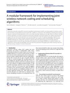
Fig. 6. System FER Performance comparison of SiSF-CFNC protocol for 2-relay scenario with and without precoder. 16-QAM is used in simulation with the channel gains η1 = η2 = 1.
B. Precoder Design Even under a proper power allocation scheme, the performance of the SySF-CFNC protocol are not so desirable. From the numerical results in the priori subsection, we can see that the system FEP of the SiSF-CFNC protocol are not achieving the full diversity gains. Besides power allocation, another effective method to improve the performance is to apply the precoder design to enlarge the value of μ. We follow the similar way of precoder design as that in [15] where precoder is designed for MIMO systems. In MIMO systems, one kind of space-time precoders is designed as the normalized Vandermonde matrix to achieve higher diversity gain [15]: ⎛ 1 1 ⎜ ⎜1 Θ = √ ⎜. L ⎝ ..
α1 α2 .. .
··· ···
1 αL
···
⎞ αL−1 1 ⎟ αL−1 2 ⎟ .. ⎟ . ⎠ αL−1 L
(15)
L×L
where {αi }N i=1 have unit modulus. And L is an arbitrary integer. If L = 2k , αi = ejπ(4i−1)/2L ; else if L = 3 × 2k , αi = ejπ(6i−1)/3L . We choose the best power allocation scheme that κ1 = κ2 = 1 N , τ = N+1 . From Theorem 1, the condition to κ = 2(N+1)
978-1-4244-2324-8/08/$25.00 © 2008 IEEE. This full text paper was peer reviewed at the direction of IEEE Communications Society subject matter experts for publication in the IEEE "GLOBECOM" 2008 proceedings.
achieve the full diversity gain function for d1 and d2 is N N X Y |us1 ,i |2 (|us1 ,i |2 + |us2 ,i |2 ) 6= 0, i=1
i=1
N N X Y |us2 ,i |2 (|us1 ,i |2 + |us2 ,i |2 ) 6= 0. i=1
(16)
i=1
In 2 − N − 2 multicast system, we should jointly consider the successful reception of both sources’ symbols in each destination, that is, the design of precoder in such system should take both sources into account. From (16), we should make each |us1 ,i |2 + |us2 ,i |2 6= 0 (i = 1, · · · , N ) to achieve higher diversity gain. We denote Θs1 and Θs2 as the precoders for the s1 and s2 respectively. They come from the N × 2N matrix Θr composed by arbitrary N rows of the 2N × 2N matrix Θ2N . Then the odd columns of the Θr becomes to Θs1 and the even columns of the Θr becomes to Θs2 , i.e., ⎞ ⎛ 2(N−1) 1 α12 · · · α1 ⎟ ⎜. .. .. ⎟ ⎜ .. . . ⎟ ⎜ 1 ⎜ ⎟ Θs1 = √ ⎜1 αi2 · · · αi2(N−1) ⎟ (17) ⎟ ⎜ N ⎜. .. .. ⎟ . ⎠ ⎝. . . 2(N−1) 2 1 αN · · · αN N×N ⎛ 2N−1 ⎞ 3 α1 α1 · · · α1 ⎜ .. .. .. ⎟ ⎜ . . . ⎟ ⎟ 1 ⎜ 2N−1 ⎟ 3 ⎜ Θs2 = √ ⎜ αi αi · · · αi (18) ⎟ N⎜ . ⎟ . . .. .. ⎠ ⎝ .. 2N−1 3 αN αN · · · αN N×N Fig. 5 show the precoder design for SiSF-CFNC protocol. The transmitted signals in each source after precoding and amplification during a frame period can be expressed as √ xs1 = 2Eκ(Θs1 ps1 ), √ (19) xs2 = 2Eκ(Θs2 ps2 ). Then after precoding, the product terms of (16) becomes ⎛¯ ¯2 ¯ ¯2 ⎞ N ¯N−1 ¯ ¯ ¯N−1 Y X X ¯ ¯ ¯ ¯ ⎝¯ (20) α2n αi2n+1 us2 ,n ¯ ⎠. i us1 ,n ¯ + ¯ ¯ ¯ ¯ ¯ i=1
n=0
n=0
Since Θ contains irrational numbers, it is evident that (20) will be equal to zero if and only if (iff) all symbols are correctly decoded, which ensures higher diversity gain. Fig. 6 shows the performance comparison. From the figure, we can see the system diversity gain (the slope of the curves) is distinctly enhanced with the designed precoder. V. C ONCLUSION We design the SiSF-CFNC protocol for the 2 − N − 2 multicast systems in complex filed to achieve higher system throughput by consuming the less transmission time slots. Meanwhile, we define and deduce the system FEP as the
measurement to evaluate the protocol. According to the expressions of system FEP, we conclude that through a proper power allocation scheme can improve the system performance. Precoder is another effective way to achieve higher diversity gain. We then design the precoder for the protocol. Simulations show our precoder can distinctly improve the system performance. ACKNOWLEDGMENT This work is supported by NSF China #60672067 #60702046 #60832005, by NSF Shanghai #06ZR14041, by Shanghai-Canada NRC #06SN07112, by Cultivation Fund of the Key Scientific and Technical Innovation Project, Ministry of Education of China #706022, by Program for New Century Excellent Talents in University #NCET-06-0386, and by PUJIANG Talents #07PJ4046 #08PJ14067. China Ministration of Education (No. 20070248095); Sino-Sweden Joint Project (No. 2008DFA11630); Qualcomm Research Grant; Huawei Research Grant; Shanghai Innovation Key Project (08511500400). R EFERENCES [1] R. Ahlswede, N. Cai, S.-Y. R. Li and R. W. Yeung, “Network infomation flow,” IEEE Trans. Inf. Theory, vol. 46, no. 4, pp. 1204-1216, Jul. 2000. [2] S.-Y. R. Li, R. W. Yeung, and N. Cai, “Linear network coding,” IEEE Trans. Inf. Theory, vol. 49, no. 2, pp. 371-381, Feb. 2003. [3] R. Koetter and M. Medard, “An algebraic approach to network coding,” IEEE/ACM Trans. Netw., vol. 11, no. 5, pp. 782-795, Oct. 2003. [4] T. Ho, M. Medard, R. Koetter, D. R. Karger, M. Effros, J. Shi, and B. Leong, “A random linear network coding approach to multicast,” IEEE Trans. Inf. Theory, vol. 52, no. 10, pp. 4413-4430, Oct. 2006. [5] S. Zhang, S.-C. Liew, and P. P. Lam, “Hot topic: Physical-layer network coding,” in Proc. of 12th Annual International Conference on Mobile Computing and Networking (MobiCom), Los Angeles, CA, Sept. 23-26, 2006, pp. 358-365. [6] T. Wang and G. B. Giannakis, “High-throughput cooperative communications with complex field network coding,” in Proc. of 41st Annual International Conference on Information Sciences and Systems (CISS), Baltimore, MD, Mar. 14-16, 2007, pp. 253-258. [7] L. Xiao, T. E. Fuja, J. Kliewer, and D. J. Costello, “A network coding approach to cooperative diversity,” IEEE Trans. Inf. Theory, vol. 53, no. 10, pp. 3714-3722, Oct. 2007. [8] S. Fu, K. Lu, Y. Qian, and M. Varanasi, “Cooperative network coding for wireless ad-hoc networks,” in Global Telecommunications Conference (GlobalComm), Washionton, D.C., Nov. 26-30, 2007, pp. 812-816. [9] P. Popovski and H. Yomo, “Wireless network coding by amplify-andforward for bi-directional traffic flows,” IEEE Communications Letters, vol. 11, no. 1, pp. 16-18, Jan. 2007. [10] P. Popovski and H. Yomo, “Physical network coding in two-way wireless relay channels,” in Proc. Conference on Communications (ICC), Glasgow, Scotland, Jun. 24-28, 2007, pp. 707-712. [11] Y. Wu, P. A. Chou, and S. Kung, “Information exchange in wireless network with network coding and physical-layer broadcast,” Microsofr Reserach, Redmond, WA, Tech. Rep. MSR-TR-2004-78, Aug. 2004. [12] H. P. F. Frank and D. K. Marcos, Cooperation in wireless networks: Principles and applications, Netherlands: Springer, 2006. [13] R. U. Nabar, H. B¨ olcskei, and F. W. Kneubuhler, “Fading relay channels: Performance limits and space-time signal design,” IEEE J. Sel. Areas Commun., vol. 22, no. 6, pp. 1099-1109, Aug. 2004. [14] Y. Ding, J.-K. Zhang, and K. M. Wong, “The amplify-and-forward half-duplex cooperative system: Pairwise error probability and precoder design,” IEEE Trans. Signal Process., vol. 55, no. 2, pp. 605-617, Feb. 2007. [15] Y. Xin, Z. Wang, and G. B. Giannakis, “Space-time diversity systems based on linear constellation precoding,” IEEE Trans. Wireless Commun., vol. 2, no. 2, pp. 294-309, Mar. 2003.
978-1-4244-2324-8/08/$25.00 © 2008 IEEE. This full text paper was peer reviewed at the direction of IEEE Communications Society subject matter experts for publication in the IEEE "GLOBECOM" 2008 proceedings.