Progress In Electromagnetics Research B, Vol. 54, 357–383, 2013
COMPLEX SURFACE WAVE MODES OF PLASMA COLUMN LOADED CLOSED CYLINDRICAL WAVEGUIDE
Ersoy Kelebekler* Umuttepe Campus Technical Education Faculty Electronics and Computer Dep., Technical Education Faculty, Kocaeli University, Kocaeli 41380, Turkey Abstract—The complex dispersion characteristics of the surface wave modes of plasma column loaded closed cylindrical waveguides have been investigated. The numerical results for partially or fully plasma loaded waveguides have been obtained from the Method of Moment (MOM), the exact dispersion equation and the quasistatic dispersion equation. A numerical technique based on the solution of the MoM has been proposed in order to obtain the complex propagation constant from the exact solution. The surface wave modes obtained from these methods have been presented comparatively in the figures. Thus, the insufficiency of the quasistatic approximation to obtain the complex surface wave modes has been shown. Additionally, the study involves a comprehensive literature review including physical descriptions and/or behavior in different physical media of surface wave modes and complex wave modes. 1. INTRODUCTION The propagation possibility of surface electromagnetic waves in the media having an interface with a phase velocity which does not exceed the velocity of light in the medium is an important aspect of the media [1]. In the literature, there are many studies which describe and discuss the concept of the surface waves and classify them in accordance with their physical phenomena. As a result of the studies performed onsurface waves in the 1950s and 1960s, there was confusion for definition of the surface waves. Although conclusion of General Assembly of URSI held in London in 1960 was that “there is no neat Received 9 July 2013, Accepted 18 September 2013, Scheduled 21 September 2013 * Corresponding author: Ersoy Kelebekler (
[email protected]).
358
Kelebekler
definition which would encompass all form of waves which could glide or be guided along a interface” [2], the generally accepted definition of the surface wave is that electromagnetic surface waves are waves which propagate along an interface between two different media without radiation or losing energy [3, 4]. Radiation or losing energy in the definition means that average energy converts from the surface wave field to some other forms. The surface waves were explained separately for two subclasses of waveguide, closed waveguides and open waveguides in [5] which presents some comments on the classification of waveguide modes. A comprehensive review of electromagnetic surface waves, which included studies from 1960 to 1987 was reported by Overfelt [6]. The report emphasized the mathematical analysis of surface waves supported by different structures. Some of these structures were: planar interfaces between two homogenous isotropic media composed of different material properties, or ferrite slabs, or various dielectric layers on coaxial cables; or the electric rod waveguide; or spherical structures such as the dielectric-coated conducting sphere; or elliptical dielectric waveguides. Interestingly, the surface wave that exists in plasma or the interface between plasma and a second medium was not included in the report. A surface wave produced by a plasma column is an electromagnetic surface wave which uses the plasma column as its sole propagating medium. This propagation can be considered to result from a periodic interchange of energy in the wave field with ordered kinetic energy of electrons. The wave damps while it propagates since it transfers some of its energy to the plasma at each point along the column [7]. The power flow along the surface wave of an axially magnetized plasma column has been investigated in [8–10] and the power carried by the surface wave modes have been presented as a function of frequency for different values of the column radius and the magnetostatic field in [8]. The surface waves in partially stationary plasma of finite transverse cross section were observed for the first time by Trivelpiece and Gould [11–13]. They obtained the field equations by using quasistatic approximation and also presented analytically and experimentally two types of propagation. The first described as a body wave involved change in density variation within the plasma and the second described as surface wave involved a perturbation of the surface of the plasma. In later studies, the surface wave modes of plasma column loaded cylindrical waveguides were examined in detail. Carlile examined both theoretically and experimentally the surface wave mode for the constant azimuthal variation (n = 1) and reported that this mode is a backward wave [14]. The studies of Trivelpiece &
Progress In Electromagnetics Research B, Vol. 54, 2013
359
Gould and Carlile are true, theoretically and experimentally consistent with each other, but their results were approximate because they used the quasistatic approximation as theoretical method. In fact, surface wave modes arise as forward waves and turn into backward waves at higher frequencies except in the structures with fully plasma loaded waveguides and small plasma-waveguide radii ratio with weak dc magnetic fields. This case has been shown by [15] and [16] using the exact solution as theoretical method. It has also been reinforced with experimental results in [16]. In our study, the characteristics of the surface wave modes have been investigated by using the exact solution and the quasistatic solution together and the deficiency of the quasistatic approximation has been shown numerically on the figures. Nevertheless the exact dispersion function is a twovalued function at the frequency points where the dispersion curves turn from forward wave to backward wave. At this point, the dispersion curves bifurcate and the complex waves appear. As a result of our study, the complex surface wave modes have been investigated in detail and it has been shown that the quasistatic solution does not supply the complex wave modes. The complex wave mode implies that the phase constant and the attenuation constant of the propagation constant are both nonzero. The complex wave represents the propagating waves with fading power [17]. For a physical implementation, the complex wave modes can be equivalent to evanescent modes because the electromagnetic wave expeditiously loses its power and disappears in the waveguide. In lossy guides, modes appear whose propagation constants are complex rather than purely real or purely imaginary, and the wave then propagates with attenuation due to power being absorbed into the lossy medium [18]. Complex modes can be supported by lossless guiding structures [19]. For lossless structures, the complex propagation constant always has a complex conjugate pair, which means conservation of the losslessness condition. One of the complex conjugate represents giving the energy into the system and the other represents taking the energy from the system. Thus the energy is conserved and the losslessness condition is supplied. Complex modes for closed guiding structures have been tackled in a wide range of studies. A good review of complex modes has been given by Mrozowski [20]. In this review, the complex modes in isotropic guides and gyrotropic guides and discontinuity structures have been presented by referring to studies in the literature. In the study, the complex modes in gyrotropic medium loaded guides have been investigated predominantly for gyromagnetic medium loaded waveguides. It was shown numerically and theoretically in different studies
360
Kelebekler
that the slope of the dispersion curve is infinite at the onset of a complex propagation constant and when the backward wave modes exist the complex wave modes also exist. This was shown in the dielectric loaded cylindrical waveguide [21, 22], the twolayer circular shielded waveguides with different permittivity or permeability [23], the shielded rectangular dielectric image [24, 25] and the rod waveguides [26], the planar transmission lines [27], the shielded suspended coupled microstrip line [28], the nonreciprocal finline [29], the suspended ferrite loaded strip lines [30], and the multilayered parallel plate waveguide with ferrite layers [31]. Some studies purpose to give a theoretical proof of the existence of complex wave modes [32] or the co-existence of complex and backward wave modes [19, 33] for different waveguide structures. These studies base on the matrix equivalent of the waveguide structures and derive the theoretical proof using the fundamental properties of equivalent matrix. The existence of complex and backward wave modes was proved for the general case of only inhomogeneous or only anisotropic filled waveguides with arbitrarily shaped cross sections [19]. The necessary condition for existence of complex waves was given in [32] and it is also shown that complex waves may exist in slightly perturbed homogenous guides. In later studies, the necessary and sufficient conditions for the existence of backward waves in metallic waveguides filled the media which do not include coupling between transverse and longitudinal fields (simultaneously inhomogeneous and anisotropic) were given in [34] and the proof that whenever there is a frequency region of a backward wave then there exists an adjacent region with a complex propagation constant was presented in [33]. The possibility of the existence of the complex propagation factor in bidirectional gyroelectric guides, such as plasma, was shown by applying Poynting’s theorem to a standing complex wave and giving the analytical relationship between energy, power and group/phase velocity by Chorney in [35, 36]. Firstly, phase velocity was expressed in terms of pseudo energy and power flow. Later, a useful theorem was derived that related group velocity and phase velocity directly through the true energy and the pseudo energy. Privately, these theorems are used to illustrate the dispersion characteristics of a plasma filled waveguide and it was shown that when the slope of the dispersion curve is infinite for a finite propagation constant, it indicated the onset of complex roots. In his study, Chorney stated that the answer to the question of whether this might be the onset of a complex propagation constant, or not, could only give direct computation of the dispersion relation [36]. Chorney is probably the first author to describe these new modes as complex waves and give a physical explanation for
Progress In Electromagnetics Research B, Vol. 54, 2013
361
their existence [20]. In later studies, it was shown that it was not essential in the derivation of the theorems obtained by Chorney to use a standing wave and the theorems were extended further to apply more generally [17, 37, 38]. The complex modes for the plasma column loaded cylindrical waveguide were obtained approximately in [39] where the phase constant and the attenuation constant were computed together. In the study, the structure was transformed into a multilayer dielectric structure by taking the plasma as a complex dielectric dependent on frequency and the transverse-equivalent network of the structure, based on the studies in [40, 41], was generated. It was emphasized in [39] that the transverse wavenumbers and the propagation coefficients could become complex with the introduction of complex permittivities for one or any layer of the structure. In our study the complex wave modes whose possibility of existence was shown by Chorney for plasma column loaded cylindrical waveguides, have been presented numerically by using the exact solution and the MoM. Additionally, the insufficiency of the quasistatic approximation to obtain the complex wave modes has been shown numerically. In the study, the method of moment (MoM) has been used as the main method in order to obtain the complex surface wave modes. This is because this method gives the propagation constant directly with regard to the frequency without much computing load after obtaining the transmission line equivalent of the structure analytically. Obtaining the complex propagation constant from the exact solution would have a very high computing cost, as explained in Section 3. The MoM is a widely used technique for the numerical simulation of propagation and scattering problems [42]. Harrington used the MoM in electromagnetics problems and gave its details in his fundamental book [43]. The MoM technique is based on reducing the operator equation to a system of linear equations that is written in matrix from. One of the advantages of using this method is that the results are very accurate because the equations that his method uses are essentially exact and the MoM provides a direct numerical solution for these equations. Another advantage is that it is practically applicable to geometrically complex scatter [44]. In solving an electromagnetic problem with the MoM, the dimension of the linear system in matrix form directly determines the accuracy of the solution and the duration of the computation which includes the time for constituting the coefficient of the linear equations system in matrix form and the time for solving the system. In this study, “Generalized Telegraphist’s Equations” [45] or transmission line equations for closed waveguide are utilized to generate the linear equation system of the MoM for the plasma column loaded cylindrical waveguide. In this technique,
362
Kelebekler
the dimension of the linear equations system is determined from the number of eigenfunctions used in the series expansion. For the cylindrical structure, the eigenfunctions are in terms of Bessel functions. The plasma column loaded closed cylindrical waveguides have been tackled in different studies using the quasistatic approximation [11–14, 46] or the exact solution [16, 47–51] or both [15, 52]. In these studies, the propagation characteristics of the structures have been presented on the frequency-propagation constant (ω-γ) plane called the Brillouin diagrams, because these diagrams are easily interpreted and therefore more useful to engineers and physicists [48]. A general structure of field components for anisotropic medium loaded cylindrical waveguides was given in [53]. In particular, the exact dispersion relation of the plasma column loaded cylindrical waveguide was presented in different forms with different notations in [15, 48, 51, 52]. As a contribution of our study, the complex surface wave modes of plasma column loaded cylindrical waveguides have been obtained from the exact solution for the first time. A numerical technique based on the solution of the MoM has been proposed in order to obtain the complex propagation constant from the exact solution. The surface wave modes obtained from the exact solution, the MoM and the quasistatic solution have been presented comparatively in the figures. Thus, the insufficiency of the quasistatic approximation to obtain the complex surface wave modes of the structure has been shown. This is important as it explains why the complex surface wave modes of the structure were not reported in the literature although it was tackled in many studies which usually used the quasistatic approximation. The organization of the paper is as follows. The methods used to obtain the surface wave modes are explained in the next section. The proposed numerical technique to compute the complex propagation constant is given in Section 3.1. The dispersion curves of the complex surface wave modes are presented in the numerical results in Section 3.2. The study is finalized in the conclusion of the paper. 2. METHODS The cross-section of the plasma column loaded cylindrical waveguide investigated in the study is given in Figure 1. The variation of the field in the cylindrical guide is taken as Equation (1). The medium has been assumed as lossless and sourceless. F (r, ϕ, z) = F (r)eγz+j(nϕ−ωt) (1) where γ is the complex propagation constant and described as γ = α ± jβ, where α is the attenuation constant, β the phase constant,
Progress In Electromagnetics Research B, Vol. 54, 2013
363
b
a
Figure 1. The cross-section of the plasma column loaded cylindrical waveguide. n the azimuthal variation number, ω the operating frequency, and r, ϕ, and z are the cylindrical coordinates. The normalized propagation constant is described as Γ = γ/γ0 , where γ0 is the waveguide number in free space. The permittivity in the waveguide is given in Equation (2). ½ ε˜ 0 < r < b ε(r) = (2) ε0 b < r < a where, the plasma column tensor permittivity is given in Equation (3). " # ε1 jε2 0 (3) ε˜ = ε0 −jε2 ε1 0 0 0 ε3 here, ε1 = 1 +
R2
1 , − Ω2
ε2 =
−R , Ω (R2 − Ω2 )
ε3 = 1 −
1 Ω2
(4)
and, Ω is the normalized frequency and R is the normalized cyclotron frequency. Expressions of Ω and R are given in (5). ω ωc Ω= , R= (5) ωp ωp where, ωp is the plasma frequency and ωc the cyclotron frequency. Permeability of the structure for any point of the cross-section is equal to free space permeability (µ0 ). There may be four groups of mode types for a metallic closed waveguide structure where the variation of the field along the
364
Kelebekler
propagation direction is eγz , in which the propagation constant may be a complex number. They are forward wave modes, backward wave modes, evanescent wave modes and complex wave modes. A wave is considered a forward (backward) wave if the group velocity, as indicated by the slope of the dispersion curve, is in the same (opposite) direction as the phase velocity [54]. The phase velocity (υ ph ) and the group velocity (υ gr ) are described in Equation (6). υph =
ω , γ
υgr =
dω dγ
(6)
2.1. The Exact Solution The transverse field components of anisotropic medium loaded cylindrical waveguides are in the form of the equation below [53]. ½ ¾ ∂Ez 1 ∂Ez ∂Hz 1 ∂Hz Ft (r, ϕ, z) = A erz+j(nϕ−ωt) (7) +B +C +D ∂r r ∂ϕ ∂r r ∂ϕ where, Ft is any transverse field component, Ez the z component of the electric field, Hz the z component of the magnetic field, and A, B, C, and D are coefficients obtained from Maxwell’s equations. The exact dispersion equation is derived directly from Maxwell’s equations by imposing the boundary conditions which are Ez =0 and Br =0 at r = a and the continuity conditions of Ez , Hz , Dr and Eϕ at r = b. The exact dispersion equation was given below in order to correct some misstatements in [15]. fϕ (u1 ) fϕ (u2 ) = fr (u1 ) fr (u2 ) where, u21,2 = γ02
¡ ¢h ¡ ¢ − Γ2 − 1 2 Ω2 − 1 − R2 +
R2 2 2Ω ±γ0
and,
(8)
(Γ2 − 1)2 +
4Γ2 R2
i −
(Ω2 − 1)
2 (Ω2 − 1 − R2 )
) u2i + γ 2 − γ02 (ε1 ∓ ε2 ) 1 ¡ 2 ¢ − 2 γ0 − γ 2 γ0 ε1 − γ 2 u2i + ∆ ½ k02 ε2 u2i u0 ¢ 2 −¡ 2 Hn (u0 , b) γ0 ε1 − γ 2 ui + ∆ γ02 − γ 2
n fϕ (ui ) = − b
(
2 (Ω2 − 1 −
q
R2 Ω2 R2 )
2 Ω2
¡ 2 ¢ Ω −1
(9)
Progress In Electromagnetics Research B, Vol. 54, 2013
365
·
¸¾ ±ui Jn∓1 (ui b) − , i = 1, 2 (10) Jn (ui b) ¾ ½ £ ¤ γ 4 ε2 u2i n fr (ui ) = −γ02 (ε2 ± ε1 ) u2i + γ 2 − γ02 (ε1 ∓ ε2 ) + 20 b γ − γ2 " #·0 ¡ ¢ ¸ γ 2 u2i +γ 2 −γ02 ε1 ±ui Jn∓1 (ui b) 1 ¡ 2 ¢ ¢ + 1+ ¡ 2 Jn (ui b) γ0 ε1 −γ 2 u2i +∆ γ0 ε1 −γ 2 u2i + ∆ − where,
γ02 u0 Gn (u0 , b), γ02 − γ 2
i = 1, 2
(11)
h ¡ ¢2 i ∆ = γ04 ε22 − ε1 − Γ2 Hn (u0 , b) =
(12)
Nn0 (u0 a)Jn0 (u0 b) − Jn0 (u0 a)Nn0 (u0 b) Nn0 (u0 a)Jn (u0 b) − Jn0 (u0 a)Nn (u0 b)
(13)
0
J 0 (u0 b)Nn (u0 a) − Jn (u0 a)Nn (u0 b) Gn (u0 , b) = n (14) Jn (u0 b)Nn (u0 a) − Jn (u0 a)Nn (u0 b) The exact dispersion solution has a very complex expression. Obtaining purely real or purely imaginary dispersion curves from the exact solution is easily done by using numerical techniques like the bisection method. But obtaining the complex modes is rather difficult because of the complexity of the expression. The numerical technique used to obtain the complex modes is explained in Section 3.1. 2.2. The Quasistatic Approximation For anisotropic medium loaded cylindrical waveguides, one of the most important semi analytic methods is the quasi-static approximation which has been used in numerous studies [11–15, 46, 52]. For quasistatic approximation, the field solutions are derived on the assumption that the phase velocities of waves are much less than the velocity of light. In this case, the a.c. magnetic field can be neglected and it is permissible to calculate the electric fields from a scalar potential. ~ = −∇Φ E (15) The plasma is regarded as a dielectric with a permittivity tensor. There is no free charge as below. So the scalar potential can be obtained from Laplace’s equation. ~ = ∇ · (˜ ∇·D ε · ∇Φ) = 0 (16) The electric field and the electric displacement field can easily be obtained from the expression of the scalar potential. The quasi-static
366
Kelebekler
dispersion relation is obtained as in Equation (10) by imposing the boundary conditions (Eϕ = 0 at the metallic wall, r = a and the continuity of Eϕ and Dr at the interface r = b). ε1 u
Jn0 (ub) n I 0 (γb)Kn (γa) − In (γa)Kn0 (γb) − ε2 = γ n Jn (ub) b In (γb)Kn (γa) − In (γa)Kn (γb)
(17)
where, I and K arethe modified Bessel functions of the first and second kind, respectively, and u is described as in Equation (18). r ε3 (18) u = −γ 2 ε1 The quasi-static approximation for plasma column loaded cylindrical waveguides was presented in detail by Trivelpiece and Gould [11– 13]. In their study, the resulting modes are slow modes and are transverse magnetic (TM). Yip and Le-Ngoc extended the quasi-static approximation results by investigating a wide frequency interval and they compared the results obtained from the quasistatic approximation with the exact solution [15]. 2.3. Method of Moment Maxwell’s equations are partial differentials equations. In their general form, these contain three derivatives with respect to space variables and time. As is well known, closed form solutions of Maxwell’s equations cannot be given for a general physical structure. When the exact solution does not exist for any physical structure a numerical solution, such as the finite difference method or the finite element method, or a semi analytical solution, such as the transmission line method or the MoM, is investigated in order to obtain the solution. One of the best known semi-analytical methods for closed and sourceless waveguides was given in “Generalized Telegraphist’s Equations for Waveguide” by Schelkunoff in 1952 [45]. In a classic study, Schelkunoff derived the transverse field component from the potential and the stream functions for the general structure of closed waveguides. He also gave the potential and the stream functions in terms of voltage (v), current (i) and eigen functions of the empty structure. The method is summarized briefly and the ordinary differential equations system for plasma column loaded cylindrical waveguides is obtained below. The transverse field components for the gyroelectric region are derived from the Maxwell equations by eliminating the longitudinal field components as in (19) and (20) · ¸ ~t ∂E 1 1 = − jωµ0 + ∇t ∇t . (~ez × Hz ) (19) ∂z jωε0 ε3
Progress In Electromagnetics Research B, Vol. 54, 2013
367
· ¸ ~t ∂H 1 = − jω ε˜t − ∇t ∇t . (Et × ~ez ) ∂z jωµ0
(20)
where, ~ez is the unit vector in the direction of propagation and t the transverse components. the two dimensional derivative operator is described as ∇t = ∇ − ~ez (∂/∂z ). ~ t and H ~ t may be Independent transverse electromagnetic fields E expanded in terms of the orthogonal eigenfunctions T(n) and T[n] of the empty metallic waveguide with mode voltages v(z) and mode currents i(z). ~t = E
∞ X
v(n) (z)∇t T(n) n=1 ∞ X
~t = − H
+
∞ X
v[n] (z)∇t T[n] × ~ez
(21)
n=1
i(n) (z)∇t T(n) × ~ez +
n=1
∞ X
i[n] (z)∇t T[n]
(22)
n=1
where, T(n) , T[n] and n represent TM modes, TE modes and mode number, respectively. The orthogonal eigenfunctions are presented in the terms of Bessel functions for the cylindrical structure. T(n) = An J1 (αn r)ejϕ T[n] = jBn J1 (βn r)e
jϕ
(23) (24)
The normalization coefficients An and Bn are obtained from Equation (25). ZZ ZZ ∇T(n) ∇T(n) dS ≡ χ2 T 2 dS = 1 (25) S
S
where, χ is equal to αn for TM modes and βn for TE modes. They obtained from boundary conditions that the T -function vanishes for TM modes and the normal derivation of the T -function vanishes for TE modes on the boundary. The telegraphist’s equations for the structure are obtained by substituting (22), (23), (24) and (25) into (19) and (20) as in the following equations. dv(m) (z) dz dv[m] (z) dz di(m) (z) dz di[m] (z) dz
= Z(m)(n) i(n) (z)
(26)
= Z[m][n] i[n] (z)
(27)
= Y(m)(n) i(n) (z) + Y[m](n) i[n] (z)
(28)
= Y[m](n) i(n) (z) + Y[m][n] i[n] (z)
(29)
368
Kelebekler
where, impedance and admittance coefficient matrices are described as follows. ZZ Z(m)(n) = −jωµ0 ∇T(n) ∇T(m) dS + αm vz,(m) (30) S ZZ
Z[m][n] = −jωµ0
∇T[n] ∇T[m] dS + αm vz,(m)
(31)
S
Z2π Zb Y(m)(n) = −jωε0 (ε1 − 1)
∇T(n) ∇T(m) dS
ϕ=0 r=0
Z2π
Zb
+ωε0 ε2
∇T(n) × ~ez ∇T(m) dS
ϕ=0 r=0
ZZ −jωε0
∇T(n) ∇T(m) dS
(32)
S
Z2π Zb Y(m)[n] = −jωε0 (ε1 − 1)
∇T[n] × ~ez ∇T(m) dS
ϕ=0 r=0
Z2π Zb −ωε0 ε2
∇T[n] ∇T(m) dS
(33)
ϕ=0 r=0
Z2π Zb Y[m](n) = jωε0 (ε1 − 1)
∇T(n) × ~ez ∇T[m] dS
ϕ=0 r=0
Z2π
Zb
+ωε0 ε2
∇T(n) ∇T[m] dS
ϕ=0 r=0
Z2π Zb Y[m][n] = −jωε0 (ε1 − 1)
∇T[n] ∇T[m] dS
ϕ=0 r=0
Z2π
Zb
+ωε0 ε2 ϕ=0 r=0
∇T[n] × ~ez ∇T[m] dS
(34)
Progress In Electromagnetics Research B, Vol. 54, 2013
369
ZZ −jωε0
∇T[n] ∇T[m] dS + βm iz,[m]
(35)
S
The expressions αm vz,[m] in Equation (30) and βm iz,[m] in Equation (35) are obtained from the equations below. ZZ ∞ X jω vz,(n) εzz (r)αn T(n) T(m) dS = −i(m) (36) n=1
jωµ0
S ∞ X n=1
ZZ
iz,[n]
βn T[n] T[m] dS = −v(m)
(37)
S
When the double decked integrals in the expressions are solved, the ordinary differential equations system of the telegraphist’s equations for plasma column loaded cylindrical waveguides are obtained in the form of (38). v( ) 0 0 Z( )( ) 0 v( ) d v[ ] 0 0 0 Z[ ][ ] v[ ] = Y i (38) 0 0 dz i( ) ( )( ) Y( )[ ] ( ) i[ ] Y[ ]( ) Y[ ][ ] 0 0 i[ ] The method transforms the Maxwell’s equations, containing the partial differential equations, into an ordinary differential equations system containing derivation with respect to propagation direction (z) as in Equation (38). The obtained system is also called the transmission line model of the structure. If Equation (1) is considered, the derivation with respect to propagation direction is equal to the product with γ. Thus, the ordinary differential equations system is transformed into linear algebraic equations system. In general the form of the linear algebraic equations system for fully/partially gyroelectric or gyro-magnetic medium loaded waveguides is in the form of Equation (39). · ¸ · ¸· ¸ v(p) 0 Z(p) v(p) γ(p) = (39) i(p) Y (p) 0 i(p) In this way, the problem of electromagnetic propagation in the gyro-electric medium, a plasma loaded cylindrical waveguide is converted into an eigenvalue problem. In expression (39), p is the complex frequency, γ (p) the complex propagation constant, and v(p) and i(p) are the unknown voltage and the current vectors, respectively. Additionally, Z(p) and Y (p) are the complex impedance and admittance coefficient matrices per unit length, respectively.
370
Kelebekler
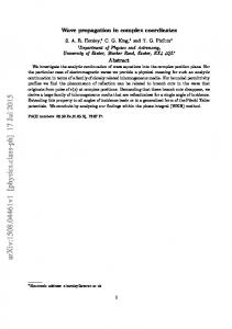
The eigenvalues of the impedance-admittance coefficient matrix gives the propagation constants of the problem. This method directly gives the relation between the propagation constant and the frequency. The dimension of the system is determined from the number of known solutions of the empty waveguide as the Fourier-Bessel series expansion. The method is called a semi-analytical method because of the necessity of truncating the infinite summation of the series at a point, while it uses known analytic solutions of the empty waveguide. This method is also called the Galerkin version of the MoM [22, 31, 55] because the expansion eigenfunctions (basis functions) and the test functions are equal to each other. In this study, the complex propagation constant obtained from the MoM is very important to decrease the computation load for the process of computing the exact propagation constant because the numerical computations have been performed around this approximate complex point on a two-dimensional plane whose axes are the phase constant and the attenuation constant. The accuracy of the approximate solution enables computation of a narrower plane. In previous studies, the authors have shown the validation of the method in the gyro-resonance region for partially or fully plasma filled structures [56, 57] and at plasma resonance region for fully [58] or partially [59] plasma filled structures. Additionally, they compared the method with two semi analytical methods, the quasi-static approximation and the asymptotic approximation, and they showed that the MoM is a better method than the other two methods for all frequencies of the gyro-resonance region [60]. 3. NUMERICAL COMPUTATIONS 3.1. A Numerical Technique to Obtain the Complex Roots of the Exact Dispersion Equation In order to obtain the dispersion curves of the surface wave modes for the plasma column loaded cylindrical wave guide, two different techniques have been used. The bisection method has been used to obtain purely real or purely imaginary propagation constants which satisfy the exact dispersion equation. The complex propagation constants have been obtained by utilizing the results acquired from the MoM. For a certain frequency, a complex numbers set which consists of complex values in the neighborhood of complex propagation constant point obtained from the MoM generates a surface. If the exact solution is computed for each of these complex propagation values, the absolute values of the exact solution gives a three dimensional shape with a clear minimum as seen in Figure 2.
Progress In Electromagnetics Research B, Vol. 54, 2013
Amplitute
1.8 1.6
x 10
371
-12
1.4 1.2 1 0.8 0.6 0.4 0.2 0 1.7
1.6
1.5 1.4 α
1.3
0.7 0.75 0.8 0.85 0.9 0.45 0.5 0.55 0.6 0.65β
Figure 2. Absolute values of the exact dispersion equation for the complex values of the normalized propagation constant. The point where the local minimum occurs on the surface is the exact complex propagation constant. In the figure, the vertical axis shows absolute values of the exact dispersion equation for the complex values of the normalized propagation constant which are stored in a 300 × 300 dimension matrix. For R = 0.5, s0 = 0.1 and Ω = 0.996, the normalized propagation constant obtained from the MoM is γ = 0.68156895 + i1.44396519 and the normalized propagation constant obtained from the exact solution is γ = 0.67954885 + i1.44598539. Here s0 is the plasma ratio in the guide and equals b/a. 3.2. Numerical Results The numerical computations have been performed for two groups of the normalized cyclotron frequency. The first is for a relatively weak magnetic field (R = 0.5) and the second is for the relatively strong magnetic field (R = 1.5) as described in [15]. The investigated structures have four different ratios of radii (s0 = 0.1, 0.5, 0.9) and s0 = 1, which is fully plasma filled waveguide. The numerical computations have been performed using MATLAB R2009b on a computer which R has an Intel°CoreTM i7 CPU 960 @ 3.20 GHz 3.19 GHz, 12GB RAM and 64 bit operating system. It is reported in [15] that the surface wave modes for the azimuthal variation n = 1 and a partially plasma column filled cylindrical waveguide except the structure R < 1.0 and small plasma ratio are first forward waves and then change to backward waves approaching
372
Kelebekler
√ resonance at Ωu / 2 for R < 1.0 and the cyclotron resonance Ω∞ = R √ 2 for R > 1.0 where, Ωu is described as Ωu = 1 + R . The surface wave modes for n = 1 and R < 1.0 are backward waves when s0 is small, e.g., s0 = 0.1. The numerical results obtained from the MoM and the exact solution corroborates the reported dispersion characteristic for purely imaginary values of γ. As a contribution of the study, it has been shown that the surface wave modes for a partially plasma column filled cylindrical waveguide except the structure R < 1.0 and small plasma ratio, e.g., s0 = 0.1 appear as evanescent waves from zero frequency and transform to forward modes at a certain frequency. The surface wave mode for the structure s0 = 0.1 and R = 0.5 appear as evanescent waves, too, but the group velocity and the phase velocity change in direction from the opposite to the same in the evanescent wave region where γ is purely real (α). For partially plasma filled guides except the structure R < 1.0 and small plasma ratio, the dispersion curves of the surface wave modes bifurcate and the complex wave modes exist at the frequency point where the forward waves change to backward waves. This characteristic is seen in Figures 3, 5, and 6. For the structure which is R < 1.0 and a small plasma ratio, e.g., s0 = 0.1, the bifurcation of the dispersion curve and appearance of the complex wave modes occurs in the evanescent wave region where the group velocity and the phase velocity change in direction from the opposite to the same as seen in Figure 4. For fully filled structures, the surface wave modes are forward waves and do not change to backwards wave and so, the complex wave modes do not exist. This has been shown in Figure 7. In the study, the surface wave modes for azimuthal variation n = −1 have not been investigated, because it is known that the surface wave modes for n = −1 are always forward waves [15] and do not change to backward waves. So, the complex wave modes do not exist. In any case, the transverse field components (Ez and Hz ) in plasma are coupled. This means that the transverse electric (TE) modes and transverse magnetic (TM) modes in which the azimuthal variation is equal to zero (n = 0) cannot exist singly except at the cutoff frequency points (γ = 0). Therefore the surface wave modes for n = 0 have not been investigated in the study. In Figure 3, the complex dispersion curve of the surface wave mode obtained from the exact solution, the MoM and the quasistatic dispersion equation for R = 0.5 and s0 = 0.5 has been given on a large normalized frequency interval from zero to Ωu . In the figures, the vertical axis below the origin shows the attenuation constant (α) and the vertical axis above the origin shows the phase constant (β) of the normalized propagation constant. The evanescent wave characteristic
Progress In Electromagnetics Research B, Vol. 54, 2013
373
is the same for all partially or fully plasma column filled cylindrical waveguides and they exist for a large frequency interval which starts from zero. Therefore, instead of a large frequency interval, important frequency regions of dispersion curves of the other structures which include forward, backward and complex wave modes have been given in the other figures.
Normalized Propagation Constant (Γ) Atten. Const. (α) Phase Const. (β)
Surface Wave Mode for R = 0.5 and s 0 = 0.5 14 12 MoM Exact Solution Quasistatic Solution
10 8
Backward
6 4 Forward
2 0
Complex
Evanescent
2 4 0
0.2
0.4 0.6 0.8 Normalized Frequency (Ω)
1
Figure 3. Complex dispersion curve of the surface wave mode for R = 0.5 and s0 = 0.5. The dispersion characteristics of the surface wave modes of partially plasma column filled guides except those with a small plasma ratio and R < 1.0 are the same. The surface wave modes start as evanescent waves from zero frequency and change to forward waves at a certain frequency, Ω = 0.823 for R = 0.5 and s0 = 0.5, and then change from forward to backward waves at a larger frequency, Ω = 0.851 for R = 0.5 and s0 = 0.5. The dispersion curves bifurcate at frequency points in which the dispersion curves change from forward to backward waves and the complex waves appear. At the frequency points in which the complex waves disappear, the dispersion curves bifurcate in the attenuation constant region of the propagation constant at a certain frequency, Ω = 1.066, and the complex wave changes to two evanescent modes. The dispersion curves of the surface wave modes obtained from the quasistatic approximation are backward waves except for those with a large plasma ratio and R < 1.0, e.g., s0 = 0.9 and R = 0.5. They change into evanescent waves at a certain frequency Ω = 0.911 for R = 0.5 and s0 = 0.5. These evanescent waves approach the higher
374
Kelebekler
order evanescent wave of the exact solution or the MoM in the larger frequency region. For a large plasma radius ratio and R < 1.0, the dispersion curves of the surface wave modes are the forward waves as seen in the left part of Figure 6. They appear at the evanescent wave region and change to forward waves. The dispersion curve of the surface wave modes obtained from the quasistatic approximation consist of only pure imaginary or pure real values of the normalized propagation constant because there are no complex roots supplied by the quasistatic dispersion equation in/around the complex wave regions as seen in the figures. Moreover, the dispersion curve obtained from the quasistatic approximation is not compatible with the exact solution and the MoM for small pure imaginary values or pure real values of γ. It is only compatible for large values of γ. This result corroborates the situation reported in [15] that “the electrostatic and exact analysis have the same asymptotic dispersion equation”. The dispersion curves of the surface wave mode for R < 1.0 and small plasma ratios have different characteristics, in that they do not have forward waves in the phase constant region. The dispersion curves bifurcate and the complex waves appear in the attenuation constant region. This characteristic is seen in Figure 4. This is a different case from classical closed waveguide structures in which the complex wave modes appear in an adjacent frequency region of backward wave modes in the phase constant region as given in [21–31]. For s0 = 0.1 and R = 0.5, the dispersion curve changes direction and bifurcates at Ω = 0.9887 and the complex wave appears in the frequency interval between Ω = 0.9887 and Ω = 1.0159 as seen in Figure 4. The attenuation constant part of the complex dispersion curve bifurcates at the frequency point where the complex wave disappears and the two evanescent waves appear. The quasistatic dispersion curve is not compatible with the exact solution and the MoM for small pure imaginary values of the normalized propagation constant. The dispersion curves of surface wave modes for R = 1.5 and s0 = 0.1 and for R = 1.5 and s0 = 0.5 are given in Figure 5 on the left and right sides, respectively. They have similar characteristics to the exact solution and the MoM and the quasistatic approximation. The dispersion curve for R = 1.5 and s0 = 0.1 bifurcates at Ω = 1.757 and the complex waves exist through the frequency point Ω = 1.792. For R = 1.5 and s0 = 0.5, the complex waves exist in the frequency interval between Ω = 1.592 and Ω = 1.934. The dispersion curves of surface wave modes for large plasma ratios, s0 = 0.9, are given on the left side for R = 0.5 and the right side for R = 1.5 in Figure 6. The dispersion curves obtained from
Progress In Electromagnetics Research B, Vol. 54, 2013
375
Surface Wave Mode for R = 0.5 and s 0 = 0.1 0,2 β
8
0
6
0,2
4
α
Normalized Propagation Constant (γ) α β
10
2
0,4 0,6 0.9887
0
0.9887
0.9888
2 MoM Exact Solution Quasistatic Solution
4
6 0.92 0.94 0.96 0.98 1 1.02 1.04 1.06 1.08 Normalized Frequency (Ω)
1.1
Figure 4. Complex dispersion curve of the surface wave mode for R = 0.5 and s0 = 0.1. R = 1.5 and s 0 = 0.1
R = 1.5 and s 0 = 0.5 20 18
MoM Exact Quasistatic
12
16 14
8
12 β
10
6
10 8
4
6
2
4 2
0
0
2
α
Normalized Propagation Constant (Γ) α β
14
1.7
1.75 Ω
1.8
2 1.2
1.4
1.6 Ω
1.8
Figure 5. Complex dispersion curve of the surface wave mode for R = 1.5 and s0 = 0.1 and for R = 1.5 and s0 = 0.5. the exact solution and the MoM are similar. They exist as evanescent waves from zero frequency to Ω = 0.536 for R = 0.5 and Ω = 1.136 for R = 1.5 and change to forward waves. The complex waves exist from the bifurcation point Ω = 0.792 for R = 0.5 and Ω = 1.51 for R = 1.5 to Ω = 0.966 for R = 0.5 and Ω = 1.649 for R = 1.5. The dispersion
376
Kelebekler R = 0.5 and s 0 = 0.9
R = 1.5 and s 0 = 0.9
25
50
20
40 β
30
10
20 10
5
0
0
10 20 0.5 0.6 0.7 0.8 0.9 Ω
MoM Exact Quasistatic
15
α
Normalized Propagation Constant (Γ) α β
60
5 10 1
1.2
1.4
1.6
Ω
Figure 6. Complex dispersion curve of the surface wave mode for R = 0.5 and s0 = 0.9 and for R = 1.5 and s0 = 0.9. characteristic obtained from the quasistatic dispersion equation for R = 0.5 and s0 = 0.9 is different form the other partially plasma loaded structures. It appears as evanescent modes in the attenuation constant region and changes to forward waves at the frequency point, Ω = 0.646. For the structure, it is compatible with the exact solution and the MoM for large values of the propagation constant. The surface wave mode obtained from the quasistatic dispersion equation is the backward wave. It turns into the evanescent wave at the frequency point, Ω =1.561 for R = 1.5. In Figure 7, the dispersion curves of the surface wave modes for fully plasma filled cylindrical wave guides have been given for R = 0.5 and R = 1.5. In order to remove the unidentified in the solutions, the plasma ratio has been taken as s0 = 0.9999999 for numerical computations. While the plasma ratio approaches s0 = 1.0, the backward waves, which exist for partially plasma filled guides, disappear. The dispersion curves of the surface wave modes obtained from the exact solution and the MoM start from zero frequency as evanescent waves and change to forward waves at a certain frequency, Ω = 0.398 for R = 0.5 and Ω = 1.084 for R = 1.5. The dispersion curves for large values of the normalized propagation constant go to infinity while the normalized frequency approaches the normalized cyclotron frequency, R. The quasistatic dispersion equation for fully plasma filled cylindrical waveguides supplies only for Ω = R and so it is compatible with the exact solution and the MoM only for large values of γ.
Progress In Electromagnetics Research B, Vol. 54, 2013
377
The surface wave modes for partially plasma column loaded cylindrical waveguides are √ backward waves while approaching the resonance at Ω∞ = Ωu / 2 for R < 1.0 and the cyclotron resonance Ω∞ = R for R > 1.0. The frequency values of bifurcation points, where the slope of the dispersion curves is infinite and the complex waves appear, are getting smaller and approach the resonance points Ω∞ = 0.792 for R = 0.5 and Ω∞ = 1.5 for R = 1.5 while the plasma-waveguide ratio is getting bigger. Nevertheless values of the propagation constant at the bifurcation point are getting bigger while s0 is getting bigger as seen in Figure 3 to Figure 6. For fully plasma structures, the surface wave modes are forward waves and approach infinity at the same resonance frequency as partially plasma loaded structures. While the plasma ratio is getting bigger for R < 1.0, the frequency point where the dispersion curves change direction and the complex waves appear moves from the attenuation constant region as seen in Figure 4 into the phase constant region as seen in Figure 3. The changing direction and the bifurcation of the dispersion curve occurs with bigger values of the propagation constant in the phase constant region, while the plasma ratio is bigger as seen in Figures 3, 5, and 6 respectively. When the plasma ratio arrives s0 = 1.0, fully plasma filled guide, the dispersion curves of the surface wave modes do not turn from forward wave to backward wave and, so, the complex waves do not exist as seen Figure 7. R = 0.5 and s 0 = 1.0 10 MoM Exact Quasistatic
8 6
16 14
β
Normalized Propagation Constant (Γ) α β
R = 1.5 and s 0 = 1.0 20 18
12
12 10 8
4
6 2
4 2 α
0 2
0 2
0
0.125 0.25 0.375 0.5 Ω
0
0.5
1
1.5
Ω
Figure 7. Complex dispersion curve of the surface wave mode for R = 0.5 and s0 = 1.0 and for R = 1.5 and s0 = 1.0.
378
Kelebekler
4. CONCLUSION The complex dispersion characteristics of the surface wave modes of plasma column filled cylindrical waveguides have been investigated in this study. The surface waves of partially or fully plasma filled guides have been obtained from the exact solution, the MoM and the quasistatic approximation. The complex propagation constants which appear at the frequency point where the backward waves disappear or change to forward waves, which means that the slope of the dispersion curve is infinite have been obtained from the exact solution with the aid of near approximate value of the point obtained from the MoM. The dispersion characteristics of the surface wave modes of the partially plasma filled cylindrical waveguides, excluding those with a small plasma ratio and R < 1.0 are the same. They start as evanescent waves from Ω = 0 and change to the forward waves at a certain frequency. They change from forward waves to backward waves at higher frequencies than the frequency points at which they change to forward waves. The dispersion curves bifurcate and the complex waves appear at the frequency points where the dispersion curves change from forward waves to backward waves. In the higher frequency regions, the complex waves disappear and the dispersion curves bifurcate from the attenuation constant branch and two evanescent waves appear. For dispersion curves of the surface wave modes of the fully plasma filled cylindrical waveguides, the backward waves and, therefore also the complex waves do not exist. They appear as evanescent waves and change to forward waves. The dispersion curves of the surface wave modes for large values of the normalized √ propagation constant approach infinity at the resonance of Ωu / 2 for R < 1.0 and the resonance of R for R > 1.0. The dispersion curves obtained from the quasistatic dispersion equation are compatible with the exact solution and the MoM only for large pure imaginary and pure real values of the normalized propagation constant. Moreover, the complex values of the propagation constant do not supply the quasistatic dispersion equation. Therefore, the complex dispersion curves of the surface wave modes are not obtained from the quasistatic approximation. When the MoM and the quasistatic approximation are compared, it is seen that validation of the MoM is higher than validation of the quasistatic approximation. ACKNOWLEDGMENT This work supported by Kocaeli University Research Project No. 201034. I would like to thank to Prof. Namık Yener for his guidance and
Progress In Electromagnetics Research B, Vol. 54, 2013
379
contributions to the study. REFERENCES 1. Aleksich, N. B., Y. M. Aliev, and A. A. Frolov, “Substantially nonlinear new surface modes at plasma vacuum interface,” J. Experimental and Theoretical Physics Lett., Vol. 51, No. 5, 299– 301, 1990. 2. Wait, J. R., “A note on surface waves and ground waves,” IEEE Trans. Antennas Propag., Vol. 13, No. 6, 996–997, 1965. 3. Goubau, G., “On the excitation of surface waves,” Proc. IRE, Vol. 42, 865–868, 1952. 4. Barlow, H. M. and A. L. Cullen, “Surface waves,” Proc. IEE, Vol. 100, Part III, 363–364, 1953. 5. Karbowiak, A. E., “Some comments on the classification of waveguide modes,” Proc. IEE, Vol. 107, No. 32, 85–90, 1960. 6. Overfelt, P. L., “Review of electromagnetic surface waves: 1960 through 1987,” Final Report, Naval Weapons Center, China Lake, CA, 1987. 7. Moisan, M., et al., “Proporties and applications of surface wave produced plasmas,” Rev. Phys. App., Vol. 17, No. 11, 707–727, 1982. 8. Yip, G. L. and S. R. Seshadri, “Surface waves along an axially magnetized plasma column,” Canadian J. Physics, Vol. 45, 2889– 2911, 1967. 9. Yip, G. L., S. R. Seshadri, and J. L. Yen, “Numerical and asymptotic solutions of the dispersion equation for dipolar surface waves along a magnetoplasma column,” Canadian J. Physics, Vol. 39, 6100–6102, 1968. 10. Bevc, V., “Surface and bulk waves on axially magnetized plasma columns,” J. Applied Physics, Vol. 40, No. 2, 633–640, 1969. 11. Trivelpiece, A. W., “Slow wave propagation in plasma waveguides,” Ph.D. Dissertation, California Institute of Technology, Pasadena-California, 1958. 12. Gould, R. W. and A. W. Trivelpiece, “A new mode of wave propagation on electron beams,” Prod. the Symposium on Electronic Waveguides, 215–228, Polytechnic Press, 1958. 13. Trivelpiece, A. W. and R. W. Gould, “Space charge waves in cylindrical plasma columns,” J. Applied Physics, Vol. 30, No. 11, 1784–1793, 1959.
380
Kelebekler
14. Carlile, R. N., “A backward-wave surface mode in a plasma waveguide,” J. Applied Physics, Vol. 35, No. 5, 1384–1391, 1963. 15. Yip, G. L. and S. Le-Ngoc, “Dispersion characteristics of the dipolar modes in a waveguide partially filled with a magnetoplasma column,” Canadian J. Physics, Vol. 53, 1163– 1178, 1975. 16. Ivanov, S. T., E. G. Alexov, and P. N. Malinov, “Symmetrical electromagnetic waves in partially-filled plasma waveguide,” Plasma Physics and Controlled Fusion, Vol. 31, No. 5, 941–953, 1989. 17. Laxpati, S. R. and R. Mittra, “Energy considerations in open and closed waveguides,” IEEE Trans. Antennas Propag., Vol. 13, No. 6, 883–890, 1965. 18. Tamir, T. and A. A. Oliner, “Guided complex waves. Part I–II,” Proc. IEE, Vol. 110, No. 2, 310–334, 1963. 19. Omar, A. S. and K. F. Sch¨ unemann, “Complex and backwardwave modes in inhomogeneously and anisotropically filled waveguides,” IEEE Trans. Microw. Theory Tech., Vol. 35, No. 3, 268–275, 1987. 20. Mrozowski, M., “Guided electromagnetic waves properties and analysis,” 267–346, John Wiley and Sons Inc., 1997. 21. Clarricoats, P. J. B. and K. R. Slinn, “Complex modes of propagation in dielectric loaded circular waveguide,” Electronics Lett., Vol. 1, No. 5, 145–146, 1965. 22. Noble, D. F., “Circuit properties of dispersive coupled transmission lines and waveguides,” Ph.D. Dissertation, Cornell University, NY, 1971. 23. Raevskii, S. B., “Complex waves in a two-lawyer circular shielding waveguide,” 82–85, Gorkii Polytechnic Institute, 1972. 24. Crombach, U., “Complex waves on shielded lossless rectangular dielectric image guide,” Electronics Lett., Vol. 19, No. 14, 557– 558, 1983. 25. Fernandez, F. A., Y. Lu, J. B. Davies, and S. Zhu, “Finite element analysis of complex modes in inhomogeneous waveguides,” IEEE Trans. on Magn., Vol. 29, No. 2, 1601–1604, 1993. 26. Wells, C. G. and A. R. Ball, “Mode-matching analysis of shielded rectangular dielectric-rod waveguide,” IEEE Trans. on Microw. Theory Tech., Vol. 53, No. 10, 3169–3177, 2005. 27. Omar, A. S. and K. F. Sch¨ unemann, “Formulation of the singular integral equation technique for planar transmission lines,” IEEE Trans. on Microw. Theory Tech., Vol. 33, No. 12, 1313–1322, 1985.
Progress In Electromagnetics Research B, Vol. 54, 2013
381
28. Kuo, J. T. and C. K. Tzuang, “Complex modes in shielded suspended coupled microstrip lines,” IEEE Trans. on Microw. Theory Tech., Vol. 38, No. 9, 1278–1286, 1990. 29. Tzuang, C. K. and J. M. Lin, “On the mode-coupling formation of complex modes in a nonreciprocal finline,” IEEE Trans. on Microw. Theory Tech., Vol. 41, No. 8, 1400–1408, 1993. 30. Idrissi, R. R., R. Marques, and F. Medina, “Efficient analysis of magnetostatic surface waves in printed and suspended ferrite loaded strip lines,” IEEE Trans. on Microw. Theory Tech., Vol. 11, No. 4, 176–178, 2001. 31. Marques, R., F. L. Mesa, and M. Horno, “Nonreciprocal and reciprocal complex and backward waves in parallel plate waveguides loaded with a ferrite slab arbitrarily magnetized,” IEEE Trans. on Microw. Theory Tech., Vol. 41, No. 8, 1409–1418, 1993. 32. Mrozowski, M. and J. Mazur, “Matrix theory approach to complex waves,” IEEE Trans. on Microw. Theory Tech., Vol. 40, No. 4, 781–785, 1992. 33. Yener, N., “On the existence of backward waves in metallic waveguides,” Journal of Electromagnetic Waves and Applications, Vol. 18, No. 6, 769–779, 2004. 34. Yener, N., “Necessary and sufficient conditions for the existence of backward waves in metallic waveguides,” Journal of Electromagnetic Waves and Applications, Vol. 17, No. 12, 1713–1722, 2003. 35. Chorney, P., “Power and energy relations in bidirectional waveguides,” Technical Report 396, MIT Res. Lab., 1961. 36. Chorney, P., “Power and energy relations in bidirectional waveguides,” Proc. Electromagnetics and Fluid Dynamics of Gaseous Plasma, 195–210, Polytehcnic Press, New York, 1962. 37. Chorney, P., A. Bers, and P. Penfield, “Further generalization of waveguide theorems,” IEEE Trans. on Microw. Theory Tech., Vol. 15, 58–59, 1967. 38. Chorney, P. and P. Penfield, “Waveguide power-mode theorems for nonconservative systems,” IEEE Trans. on Microw. Theory Tech., Vol. 19, No. 9, 767–772, 1967. 39. Clarricoats, P. J. B., A. D. Olver, and J. S. L. Wong, “Propagation in isotropic plasma waveguides,” Proc. IEE, Vol. 113, No. 5, 755– 766, 1966. 40. Clarricoats, P. J. B. and A. A. Oliner, “Transverse-network representation for inhomogeneously filled circular waveguide,” Proc. IEE, Vol. 112, No. 5, 883–894, 1965.
382
Kelebekler
41. Clarricoats, P. J. B. and A. D. Olver, “Propagation in anisotropic radially stratified circular waveguides,” Electronics Lett., Vol. 2, No. 1, 37–38, 1966. 42. Heldring, A., J. M. Rius, J. M. Tamayo, J. Parron, and E. Ubeda, “Fast direct solution of the method of moments linear system,” IEEE Trans. Antennas Propag., Vol. 55, No. 11, 3220–3228, 2007. 43. Harrington, R. F., Field Computation by Moment Methods, Macmillan, New York, 1968. 44. Gouda, M., “The method of moment for the electromagnetic scattering from bodies of revolution,” Ph.D. Dissertation, University Collage of Boras, Sweden, 2008. 45. Schelkunoff, S. A., “Generalized telegraphist’s equation for waveguide,” Bell System Tech. J., 785–801, 1952. 46. Serafim, P. E., “Analysis of electron beam-plasma systems,” Technical Report 423, Massachusetts Institute of Technology, 1964. 47. Bevc, V. and T. E. Everhart, “Fast-wave propagation in plasmafilled waveguides,” Technical Report 262, Electronics Research Lab., University of California, Berkeley, 1961. 48. Bevc, V. and T. E. Everhart, “Fast-wave propagation in plasmafilled waveguides,” J. Electron. Control, Vol. 13, 185–212, 1962. 49. Bevc, V., “A new multipolar mode in bounded gyrotropic plasma,” J. Applied Physics, Vol. 39, No. 3, 1492–1502, 1968. 50. Bevc, V., “Wave propagation in a waveguide partially filled wih plasma in an infinite axial magnetic field,” J. Applied Physics, Vol. 38, No. 12, 4857–4866, 1967. 51. Ivanov, S. T. and E. G. Alexov, “Electromagnetic waves in a plasma waveguide,” J. Plasma Physics, Vol. 43, No. 1, 51–67, 1990. 52. Allis, W. P., S. J. Buchsbaum, and A. Bers, Waves in Anisotropic Plasmas, 132–204, M.I.T. Press, 1962. 53. Ramo, S., J. R. Whinnery, and T. V. Duzer, Fields and Waves in Communication Electronics, 1st Edition, 486–533, John Wiley and Sons Inc., 1965. 54. Shevchenko, V. V., “Forward and backward waves: Three definitions and their interrelation and applicability,” PhysicsUspekhi, Vol. 50, No. 3, 287–292, 2007. 55. Yener, N., “Algebraic function approximation in eigenvalue problems of lossless metallic waveguides: Examples,” Journal of Electromagnetic Waves and Applications, Vol. 20, No. 6, 731–745, 2005.
Progress In Electromagnetics Research B, Vol. 54, 2013
383
56. Kelebekler, E., “Investigation of the gyro-resonance region modes by using the mom for plasma column loaded cylindrical waveguide,” IEEE Electrical Design of Advanced Packaging & Systems Symposium, 1–4, Hong Kong, 2009. 57. Kelebekler, E. and N. Yener, “FarklıYapıdaki silindirik dalga kılavuzlarının dispersiyon eˇgilerinin ietim hattıe¸sdeˇ gerlikleri y¨ontemi ile elde edilmesi,” Elektrik, Elektronik, Bilgisayar, Biyomedikal M¨ uhendisliˇgi 13. Ulusal Kongresi, 217–220, Turkey, 2009. 58. Kelebekler, E. and N. Yener, “Obtaining the backwards waves of fully plasma filled cylindrical waveguide by using the MoM,” 17th Telecommunications Forum (TELFOR 2009), 895–898, Serbia, 2009. 59. Kelebekler, E. and N. Yener, “Backward wave modes of partially plasma column loaded cylindrical waveguide,” PIERS Proceedings, 1084–1088, Marrakesh, Morocco, March 20–23, 2011. 60. Kelebekler, E., “Comparison of some semi analytic methods for plasma column loaded cylindrical waveguide,” IEEE Applied Electromagnetics Conference, 1–4, India, 2009.