design space exploration, hardware-software codesign, design methodology ...... A. R. Newton, âData Management and Graphics Editing in the Berkeley. Design ...
To appear: Journal of VLSI Signal Processing.
Complexity Management in System-level Design Asawaree Kalavade Edward A. Lee
Keywords design space exploration, hardware-software codesign, design methodology management, design flow management, system-level design.
Abstract The system-level design problem spans a large design space. Typically, the designer needs to explore possible target architectures, experiment with different tools, and work with a range of constraints and optimization criteria. This design process is quite complex and involves considerable bookkeeping and management, in addition to sophisticated design tools. We believe that managing the design process is an important (albeit often neglected) part of system-level design. The contribution of this paper is in two parts. First, we present a framework for systematically managing the design process. Secondly, we illustrate how this framework can be used to manage a realistic system-level design environment that consists of a suite of sophisticated hardware and software design tools. We begin by identifying some of the desirable features of system-level design methodology management. A candidate framework that manifests these features is presented. Complex design flows with iterative and conditional behavior can be specified within the framework. The framework also supports automated scheduling of tools in a well-defined design flow. It has been implemented as the DMM domain in Ptolemy. In the second part of the paper, we describe a system-level design environment case study that we have developed within this framework. The environment, called the Design Assistant, is a complete hardware-software codesign environment. It encapsulates various codesign tools for specification, partitioning, and synthesis; their interplay can be managed efficiently by the design methodology management framework.
1 of 22
Introduction
1.0
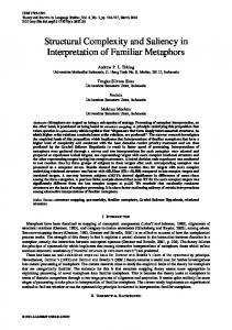
Introduction System-level design encompasses a large design space. Typically, the designer needs to
explore the possible options, tools, and architectures, choosing either automated tools or manually selecting his/her choices. As shown in Figure 1, a large number of target architectures and implementation technologies could be used to implement a system. Several optimization objectives and constraints are possible. The user also has access to a large number of design tools. The user might experiment with the design parameters, the target architectures, the optimization criteria, the tools used, or the sequence in which these tools are applied. For example, consider the design of a real-time MPEG2 encoder. One design possibility is a full hardware solution. For this architecture, the design choices include the use of standard cells vs. custom design, and in the former case, the particular synthesis tools to be used. Alternatively, a full software solution can be envisioned. In this case, the type and number of processors, the interprocessor communication fabric, and the type of scheduler are variables in the design process. A third design option is a mixed hardware-software implementation, where the hardware/software partition is either determined by
Target architectures
general-purpose
Optimization Goals Constraint Map
core-based ASIC
DSP system multiprocessor
reuse re-programmability...
FPGA
DESIGN SPACE
power latency
area Design Tools manual partitioning, ILP, Simulated Annealing... scheduler A, B, C... compiler v.1, v.2, v.3... Figure 1. The design space.
2 of 22
Complexity Management in System-level Design
Introduction
the user or by automated tools. In the manual case, the user might try mapping different combinations to hardware, for instance, the motion estimation module, or the DCT, or both. In the automated case, different partitioning algorithms of varying complexity can be used. Furthermore, each of these architectures may be optimized with respect to different criteria, such as minimizing system cost or power consumption. The design process could get quite unwieldy as the user experiments with the design methodology. Sophisticated design tools are one aspect of generating a good design. In addition, there is a need for a mechanism that systematically manages the design methodology and allows design space exploration. Tools that aid in design space exploration fall into two categories: estimation and management. Estimation tools are primarily used for what-if analysis, i.e., they give quick predictions on the outcome of applying certain synthesis or transformation tools [1][2]. Management tools orchestrate the design process, i.e., systematically control the design data, tools, and flow. In this paper, we focus on the management aspects of design space exploration; this is often referred to as design methodology management1. The paper is organized as follows. In the first half, we focus on systematizing the design methodology and describe a framework for managing the complexity of the design process. In Section 2.0, we identify the key requirements of a design methodology management framework. An infrastructure that supports these requirements is proposed in Section 3.0. We have implemented this framework within the Ptolemy [4] environment. Some details of the implementation are presented in Section 4.0. In the second part, we describe a system-level design environment case study that we have developed within this framework. In Section 5.0, we describe the Design Assistant, which is a complete hardware-software codesign environment. It encapsulates various codesign tools for specification, partitioning, and synthesis; their interplay can be managed efficiently by the design methodology management framework. Finally, in Section 6.0, we put this work in perspective with respect to other related work in this area.
1. Design methodology is defined as “the processes, techniques, or approaches employed in the solution of a problem”. Design methodology management (DMM) is formally defined as “definition, execution, and control of design methodologies in a flexible and configurable way” [3].
Complexity Management in System-level Design
3 of 22
Design Methodology Management: Desirable Features
2.0
Design Methodology Management: Desirable Features Our focus is primarily on design flow specification and management. We do not address
issues of database management, multi-user operation, or distributed tool execution. Our goal is to develop a framework that simplifies the designer’s tasks by (1) providing mechanisms that allow the design flow to be specified in an intuitive way, (2) automatically invoking the tools in the design flow whenever possible, and (3) managing the infrastructure when the user decides the sequence of tool execution. The key features required for this are discussed next. Design Flow Specification There are several important features that the design flow specification mechanism should support. Since tools involved in the system-level design process are often computationally intensive, it is important to avoid unnecessary invocation of tools. This requires that the design flow be specified in a modular way so that only the desired tools may be invoked. It should also be possible to specify the design flow hierarchically, in order to retain design modularity. The flow specification mechanism should support constructs such as conditionals and iterations. Such constructs enable specification of realistic design flows. Consider an example where an application (say MPEG2 encode) is to be mapped to a multiprocessor system. Suppose that the number of processors is not known apriori, but depends on the desired performance. The design sequence usually is to (1) estimate the number of processors required, (2) schedule the application onto these processors and compute the resultant throughput, (3) repeat step 1 if the resultant throughput does not meet the desired throughput, otherwise continue with the remaining parts of the design such as code generation and netlist generation. To express such a design flow, the flow specification mechanism should support constructs such as conditionals and iterations. The design flow should be parameterizeable, i.e., given the availability of a multiplicity of design tools, the design flow should be able to integrate a particular tool without modifying the design flow much. Consider hardware-software partitioning, for example. If the application
4 of 22
Complexity Management in System-level Design
Infrastructure for Design Methodology Management
involves few components that have obvious mappings, partitioning could be done manually. If the mappings are not obvious, an automated approach is preferred. One possibility is to use an exact (but time-consuming) integer-linear programming approach to determine the optimal mappings. Alternatively, if the application is quite complex and there are several options available for implementing the different components, an efficient heuristic could be used. The selection of the desired partitioning mechanism can be done by setting the parameters of the partitioning tool; the user should not have to construct a separate design flow for each possible partitioning mechanism. The parameters can be set either by the user, or by embedding the design choice within the design flow itself. Design Flow Execution A designer should not have to keep track of the tools that have already run and those that need to be run. When the parameters or the data associated with a tool change, the entire design flow need not be re-run; only the affected tools should be run again. Keeping track of the tools that need to be run is quite cumbersome. A mechanism that automatically determines the sequence of tool invocations is needed. This calls for a flow execution mechanism much like the “make” utility [5]. Design Flow Management Different types of tools, with varying input and output formats, are used in the systemlevel design process. In the very least, a mechanism to automatically detect incompatibilities between tools is required. Data translators could also be invoked automatically. Versions of tools and design flows also need to be maintained; it is not sufficient to just keep track of versions of data.
3.0
Infrastructure for Design Methodology Management We have developed a framework that tries to support most of the requirements discussed
Complexity Management in System-level Design
5 of 22
Infrastructure for Design Methodology Management
in the previous section. Details of the infrastructure are discussed in this section. In Section 3.1, we present the underlying models used to specify the design flow, tools, and data. In Section 3.2, we identify different types of conditions under which a tool must be invoked for execution. Such conditions are called dependencies. The flow execution mechanism analyzes the dependencies and automatically invokes tools within a design flow. Details of the flow execution mechanism are presented in Section 3.3.
3.1
Flow, Tool, and Data Model Figure 2 illustrates the user’s view of the design flow and tools. The design flow is speci-
fied as a dataflow graph2, where nodes represent tools, and arcs specify the ordering between tools. Tools encapsulate actual programs. Tool parameters specify the arguments for these programs. A tool can have multiple input and output ports. Ports are used to transfer filenames between tools. On execution, a tool sends the filename of the generated data on its output port and the receiving tool operates on the data from the file specified on its input port. A “source” tool (such as a signal generator) has no input ports, while a “sink” tool (such as a display tool) has no output ports. Ports can be either required or optional. It is important to understand the difference (a)
(b)
DESIGN FLOW
TOOL
parameters filename Tool 2
Tool N
Input Port 1 Input Port 2
optional output port TOOL J
Output Port M
Tool 1 Tool J
Tool K
program ( arguments )
Figure 2. User’s view of the design flow and tools.
2. Certain restrictions are imposed on the design flow in our implementation so as to avoid possible nondeterminacy. We defer the details to Section 4.0.
6 of 22
Complexity Management in System-level Design
Infrastructure for Design Methodology Management
between required and optional ports. A tool cannot run unless it has data (valid filenames) on all its required input ports. A tool can run even if data is absent on an optional input port. When a tool is run, it generates data on all its required output ports, but not necessarily on optional output ports. Thus, optional ports facilitate the use of conditionals and iterations in flows. To understand this, consider the multiprocessor synthesis example mentioned earlier in Section 2.0. The design problem is to synthesize a multiprocessor system that meets a desired throughput with a minimum number of processors. A possible design flow is shown in Figure 3. The tool num_proc_selector determines the number of processors required and is described hierarchically as shown in the figure. The estimator tool first estimates the number of processors needed. The estimated number of processors num_procs_est is given to a scheduler that computes the actual throughput for this number of processors. The comparator compares the actual throughput to the desired throughput and sends feedback to the estimator. The estimator has both a required input (port x), and an optional input (port y). The feedback from the comparator is fed to the optional port of the estimator. If there is no feedback, the estimator estimates the number of processors based on its own information. If there is feedback, it updates its earlier estimate. Both output ports of the estimator are optional. When the estimation loop converges, the estimator generates data on the optional output port a, otherwise it generates the data for the revised estimate on the other optional output port b. application source
num_procs
netlist generator code generator
num_proc_selector
num_procs
application
feedback
estimator y
desired throughput
a
x
scheduler
b num_procs_est
comparator
actual_throughput
Figure 3. A design flow for the multiprocessor synthesis example.
Complexity Management in System-level Design
7 of 22
Infrastructure for Design Methodology Management
While optional ports permit modeling of a wide variety of applications, their use can potentially lead to nondeterminate behavior3. In our framework, the flow scheduler flags a potential nondeterminacy and alerts the user. In most cases, the user knows what he/she had in mind when designing the design flow and can guide the system accordingly. The details of our implementation and techniques to identify nondeterminacy are described in Section 4.0. Figure 4 shows the internal model of the tools, data, and ports. Associated with each tool is a flag, called Param_Changed_Flag, which gets set when parameters of a tool are changed. Data is characterized by a filename and a timestamp. A port has several attributes: File_Namelast, File_Namenew, Time_Stamplast, Time_Stampnew, and Optional_Flag. File_Namelast and Time_Stamplast attributes store the filename and the timestamp4 of the data on a port as of the earlier invocation of the tool. File_Namenew and Time_Stampnew represent the filename and the timestamp of the data updated on a port in the current invocation of the tool. Optional_Flag indi(b)
(a)
DATA MODEL
TOOL MODEL (tool attributes) Port 1 Port 2
TOOL J
Port M
(c)
data
PORT MODEL (port attributes) PORT
filename timestamp
Param_Changed_Flag
File_Namelast File_Namenew
Optional_Flag Time_Stamplast Time_Stampnew
(d) INTERNAL REPRESENTATION OF A DESIGN FLOW connectivity Tool N
Tool 1
Param_Changed_Flag File_Namelast File_Namenew
Port M
Port 1
Time_Stamplast Time_Stampnew Optional_Flag
Figure 4. Internal representation of the tools and data. 3. By nondeterminacy we mean that the generated data may depend on the sequence used to invoke the tools. 4. The timestamp indicates when the data associated with the file was last modified.
8 of 22
Complexity Management in System-level Design
Infrastructure for Design Methodology Management
cates whether the port is required or optional. The infrastructure stores the internal representation of the design flow as shown in Figure 4-c.
3.2
Dependencies The Param_Changed_Flag and the filename and timestamp attributes are used by the flow
scheduler to determine whether a tool needs to be run. For example, if the parameters of a tool have changed since its last invocation, the tool needs to be run. Similarly, if the filename associated with a port in the current invocation of a tool is different from the filename associated with the same port in its previous invocation, this indicates a change in data, and requires the tool to be run again. We use the term dependency to qualify this behavior. We define three types of dependencies: temporal, data, and control. A tool needs to be run if any of the dependencies is alive. A temporal dependency tracks the timestamps associated with the data on the input ports of a tool. If the timestamp of the data on any input port is newer than the timestamp of the data on the corresponding port associated with the previous invocation of the tool, i.e., if Time_Stampnew > Time_Stamplast, a temporal dependency is said to be alive. A data dependency tracks changes in the filenames associated with the input ports of the tool. If the filename of the data associated with any input port is different from the filename of the data on the corresponding port associated with the previous invocation of the tool, or equivalently if File_Namelast != File_Namenew, a data dependency is said to be alive. A parametric dependency tracks parameter changes; if the parameters of a tool change, the parametric dependency is said to be alive.
3.3
Flow Management Automatic flow invocation is based on analyzing the tool dependencies and executing
tools as required. A tool is said to be enabled when all of its required input ports have data. Absence of data on the optional input ports does not affect enabling. Once enabled, a tool is checked for dependencies. A tool is invoked (run) when at least one of its dependencies is alive.
Complexity Management in System-level Design
9 of 22
Implementation: DMM Domain within Ptolemy
On execution, a tool generates data on its required output ports, and possibly on its optional output ports. Two types of flow invocation mechanisms are desired: data-driven and demand-driven. In the data-driven approach, the flow scheduler traverses the flow according to precedences. The process halts when all tools with live dependencies have been exhausted. In the demand-driven mode, the user selects a tool for execution. The scheduler traverses the predecessors and executes all tools on the path that have live dependencies. The details of the scheduler are given in the next section.
4.0
Implementation: DMM Domain within Ptolemy We have implemented the design methodology management framework as a domain5
(called the DMM domain) within Ptolemy. Ptolemy is an environment for the simulation and rapid prototyping of heterogeneous systems. The advantage of implementing the design methodology management framework as a domain within Ptolemy is that several other tools which we have developed (partitioning, synthesis, and simulation tools [6]) in Ptolemy can be accessed within the DMM framework in an integrated and seamless fashion. Stand-alone tools can also be integrated into the DMM framework. An additional advantage is that the existing Ptolemy datastructures, user-interface, database etc. are directly available to us. Note however, that the central concept of DMM does not assume Ptolemy; the DMM domain in Ptolemy is an implementation of these concepts. In what follows, we describe some details of the flow specification and execution mechanisms in this implementation. Design Flow Specification The design flow is specified graphically through the Ptolemy user interface, VEM. Figure
5. A domain in Ptolemy corresponds to a certain model of computation. Other domains include synchronous dataflow and discrete event.
10 of 22
Complexity Management in System-level Design
Implementation: DMM Domain within Ptolemy
5 shows the Ptolemy specification of the design flow for the multiprocessor synthesis example described earlier. The flow shows the connectivity between tools and is constructed by instantiating tools from a library of design tools6. The design flow is stored internally in the Oct database [7] as a netlist. Figure 5-a shows the NumProcSelector block, which determines the number of processors required. Note that this block is represented hierarchically in more detail in Figure 5-b. Also, note the use of optional ports (marked by the shaded rectangles) to express conditional behavior. The flow operates exactly like that described earlier in Section 3.1. Tool Encapsulation Tools are encapsulated within the building blocks of the DMM domain. Tool encapsulation involves writing scripts that call various programs. These programs are either routines that we have developed (such as ProcEstimator or ArchitectureGenerator in Figure 5), or other Ptolemy functions (such as a code generation routine within Ptolemy), or stand-alone executables (such as SPICE or MATLAB). The tool writer need not worry about the timestamps or the filenames associated with the tool. Figure 6 shows an example of tool encapsulation. It shows the CodeCodeGenerator
(a) Source NumProcSelector T6
GraphName (G) T2
throughput
(c)
fork T8
T3 GraphName
Simulator iterations
T7
N T1
targetArch
code{1,..N}.asm Architecture Generator
N
T4 M
modem.ptcl T9
T5 0/1
Scheduler
(b)
optional port
ProcEstimator
N
Comparator
Figure 5. (a) The design flow for the multiprocessor synthesis example, specified within the DMM domain in Ptolemy, (b) hierarchical description of NumProcSelector, (c) the control panel associated with the DMM domain. 6. We have developed a library of tools. Some of the tools such as ProcEstimator and ArchitectureGenerator contain routines that have been developed from scratch, while others such as CodeGenerator and Scheduler are calls to existing routines within Ptolemy.
Complexity Management in System-level Design
11 of 22
Implementation: DMM Domain within Ptolemy
Generator tool from the multiprocessor synthesis example. CodeGenerator generates a multiprocessor implementation (multiple programs) for the input application. It uses a code generation routine within Ptolemy (ptkGenCode) to generate the code. CodeGenerator has two inputs (both required): the application description (graph) and the number of processors (numProcs). The tool generates programs for all the processors. The output of the tool is specified as a file (codeFileNames) containing the names of the generated programs. The Code Generator has a parameter (targetArch) that specifies the assumed target architecture, sharedMem in this case. The function “go()” contains the code that gets executed when the tool is invoked. When invoked, the tool first reads in the name of the file containing the graph (graphName). The functions getName(), getDomain() and getHandle() obtain the identifiers for the application pointed to by graphName. The number of processors is read into the variable numberProcs by scanning the input file procFileName. The Ptolemy routine that generates the code (ptkGenCode) is then called with the application identifiers, the target architecture, and the number of processors. The result is defstar { name { CodeGenerator } domain { DMM } input { name { graph } } input { name { numProcs } } output { name { codeFileNames } } state { name { targetArch } default { sharedMemory } } go { // get application name and identifiers graphName = graph.getFileName(); name = getName( graphName ); domain = getDomain( graphName ); handle = getHandle( graphName ); // get number of processors procFileName = numProcs.getFileName(); fp = fopen(procFileName, “r”); fscanf(fp, “%d”, &numberProcs); // run tcl command for code generation Tcl_VarEval(ptkInterp, “ptkGenCode”, name, domain, handle, targetArch, numberProcs, fout); // generate output file names codeFileNames.putFileName(fout); fclose(fp); } }
Figure 6. An example of Tool encapsulation: CodeGenerator tool.
12 of 22
Complexity Management in System-level Design
Implementation: DMM Domain within Ptolemy
written into the file codeFileNames. Design Flow Scheduler (DesignMaker) In Section 3.2, we discussed the various attributes associated with a tool (Param_Changed_Flag, Time_Stamplast, File_Namelast, Time_Stampnew, File_Namenew, and Optional_Flag). The flow scheduler, called DesignMaker, analyzes these attributes to determine whether a tool has a live dependency and automatically invokes the tools in the appropriate sequence. The flow scheduler is essentially a dynamic dataflow scheduler. We will not go into the details of the scheduler, which, along with issues of nondeterminacy, are described in [6]. Figure 5-c shows the control panel of DesignMaker. There are three possible approaches to executing the flow: (1) The user opts to run the entire design flow (Run All), or (2) The user selects a certain tool upto which the flow should be executed (Run Upto), or (3) The user asks for a specific tool to be invoked (Run This). In the Run All mode, the flow scheduler traverses the design flow, starting with the source tool, executing tools as necessary. To do this, it maintains a list of enabled tools. Recall that an enabled tool is one that has data on all of its required input ports. An enabled tool is checked for its dependencies and invoked for execution if any of its dependencies is alive. On execution, the appropriate descendents of the tool are identified, and their corresponding input ports are marked. If all the required input ports of a descendent tool are marked, the descendent tool is added to the list of enabled tools. As mentioned earlier, it is possible that a flow may have a nondeterminate behavior due to the presence of optional ports. Currently, the flow scheduler does very strict checking and flags flows that are possibly nondeterminate. Some of these flagged flows may be determinate if the user has taken appropriate care in designing the flow. In such a case, the user can choose to use our flow scheduler at his/her risk. Alternatively, the user can schedule the tools manually in the sequence desired, by using the Run This mode. In the Run Upto mode, the user selects a certain tool upto and including which the flow Complexity Management in System-level Design
13 of 22
System-level Design using DMM — Case Study
should be executed. All the predecessors of the selected tool are identified and tagged. The design flow is then traversed as in the Run All mode; only the tagged tools are executed. In the current implementation, we support this mode for acyclic flows only. The DesignMaker control panel also shows other options such as animation, Save Facet, and Reset Design Status. The graphical animation mode highlights tools as they are executed and can be used to view the scheduling sequence. The textual animation option prints the sequence in which the tools are executed. The Save Facet option allows the user to save the current design flow to the Oct database. This saves the attributes associated with the most recent execution of each tool to the Oct database. When the design flow is retrieved in a future design session, the saved attributes get loaded in. The Reset Design Status option allows the user to override this; the flow scheduler treats the design flow as a new flow where none of the attributes have been set. The GUI for the DesignMaker has been implemented in Tcl/Tk.
5.0
System-level Design using DMM — Case Study The use of the DMM framework in managing the complexity of the system-level design
process is demonstrated next with the help of a case study. We describe an entire codesign environment for a mixed hardware-software end solution. The environment is managed entirely through the DMM framework.
5.1
Design Assistant (A Hardware-Software Codesign Environment) We have developed an environment called Design Assistant for the system-level codesign
of mixed hardware-software systems. Figure 7 shows a part of the Design Assistant implemented in the DMM domain. The design flow shown is targeted towards the design of signal processing applications specified in the synchronous dataflow (SDF) model of computation [8], running on an architecture consisting of a single programmable processor (in particular, the DSP 56000) and
14 of 22
Complexity Management in System-level Design
System-level Design using DMM — Case Study
simple.sdf
simple.sdf
Manual Partitioning T2
Source T1
T4 Hardware Synthesis-1 (Silage) hw1.sil hw1.pt, hw2.sil .. hw2.pt,...
layout
Hardware - Retargeting sw.pt Synthesis-2 - Scheduling (Hyper) sw.asm - Synthesis Graph T6 Generation Software T3 Synthesis (CG56) T5
Figure 7. The Design Assistant, as implemented in the DMM domain.
custom hardware (in particular, a standard-cell based hardware such as that synthesized by a highlevel synthesis tool like Hyper [9]). Other variants in the architecture and design tools are possible by changing the appropriate parameters in the flow. We next describe this flow and the associated tools in some detail. Source (T1) outputs the SDF graph G specified by GraphName (say simple.sdf). G is then partitioned into hardware and software by the partitioning tool T2. The Design Assistant supports both manual and automated partitioning [6]. Figure 8 shows the behavior of T2 when configured for manual partitioning. The application, which is to be partitioned, is automatically displayed by the partitioning tool (Figure 8-a). The partitioning tool also brings up a selection panel to aid in manual partitioning (Figure 8-b). The user can then select parts of the application and assign them to hardware or software. Supsimple.sdf
IIDGaussian Ramp
Gain
Add
FIR
(b) (a)
Figure 8. Run-time behavior of the Design Assistant with manual partitioning.
Complexity Management in System-level Design
15 of 22
System-level Design using DMM — Case Study
pose that the nodes IIDGaussian and FIR are mapped to software, and the nodes Gain and Add are mapped to hardware. The nodes Ramp and Blackhole correspond to the stimulus and monitor nodes. Once partitioned, the hardware and software components are synthesized by T6 and T5 respectively. T6 calls a high-level synthesis tool Hyper, while T5 invokes the DSP56000 code generation routines in Ptolemy. Before T6 and T5 can be invoked, the partitioned design has to be processed to generate data compatible with these synthesis tools. In particular, the hardware synthesis tool T6 synthesizes a separate datapath for each node mapped to hardware (Gain and Add in our example). At the input of T6, the specification of each node needs to be in Silage. T4 generates this Silage description for each node, starting with a netlist specification of the node. This netlist description, called the hardware graph, is generated by T3 . T6 uses the Silage code generated by T4 to generate the final layout for the hardware components by running Hyper. The software synthesis tool T5 generates a single assembly code file corresponding to all
Add
Gain
hw1.pt hardware graphs software graph
hw2.pt software ordering
T3
IIDGaussian1 Send0 sw.pt Receive1
FIR1
Send2
Figure 9. Hardware and software graphs generated by T3. The actual hardware and software components can then be synthesized from these graphs.
16 of 22
Complexity Management in System-level Design
System-level Design using DMM — Case Study
the software-mapped nodes. It receives as its input, a netlist of all the nodes mapped to software. This netlist, called the software graph, is generated by T3. In order to generate code, T5 also needs the order in which the software-mapped nodes execute. This schedule is also generated by T3. The goal of T3 is to transform the high-level application description into software and hardware graphs (based on the selected partition) that can then be synthesized into the final implementations and also to generate a schedule for the execution of the nodes. A separate hardware graph is generated for each node mapped to hardware. A single software graph is generated for all the nodes mapped to software. The software graph includes the Send and Receive nodes corresponding to data transfers across the hardware-software interface. Figure 9 shows the outputs generated by T3 for the graph simple.sdf shown in Figure 8. The outputs of T4 and T5 are shown in Figure 10. More details of the partitioning and hardware and software synthesis tools can be found in [6]. The Design Assistant thus contains a number of point tools for the various aspects of the codesign process. We have shown just one possible design flow for codesign. Since the Design
hw1.sil hardware graphs
T4 HW synthesis-1
hw2.sil
silage description for each node mapped to hardware
software graph
T5
sw.asm
SW synthesis
generated assembly code
schedule
Figure 10. Silage and assembly code generated by the hardware and software synthesis tools.
Complexity Management in System-level Design
17 of 22
Related Work
Assistant is implemented in the DMM framework, the design flow can be parameterized, run partially, or entirely. The design methodology management framework takes care of all the bookkeeping, making it easy to efficiently explore the design space. Suppose that the user wants to experiment with a different partitioning mechanism, say use an automated partitioning tool. The parameters of the Partition tool (T2) are changed accordingly and the RunAll command is reissued. In this case, all the subsequent tools then get invoked automatically. Alternatively, the user might just be interested in the estimated throughput of the new partition. In this case, the user can issue the command RunUpto Partition, and only that tool is invoked. Suppose that the user wants to try out a different software synthesis strategy. The parameters of the Software Synthesis tool (T5) can be set accordingly and the Run All command issued. In this case, only T5 is invoked, since none of the other tools have live dependencies. The automated dependency analysis and scheduling avoids unnecessary invocation of tools, which could otherwise be time-consuming. The tool encapsulation mechanism also serves the purpose of relieving the user from remembering mundane details such as where a tool resides or the command-line arguments of a tool. In summary, our framework makes it possible to easily experiment with the design methodology, tools, and constraints. The user no longer has to keep track of the logistics of the design process, but can instead focus on the more creative aspects. Note that this particular case study does not exhibit conditional flows unlike the multiprocessor example discussed in the paper. As mentioned earlier, though, DMM can handle conditional flows. The multiprocessor example has also been implemented as an independent environment using DMM [10].
6.0
Related Work Design methodology management (DMM) as such is not new; traditional DMM systems
18 of 22
Complexity Management in System-level Design
Related Work
are used quite extensively in the physical VLSI design process. The DMM systems used in the physical VLSI design process focus primarily on data management (i.e., maintaining consistent versions of data) [7] and tool management (i.e., invoking a user-specified tool after ensuring that the preconditions for enabling it are satisfied) [11][12][13]. Commercial CAD frameworks such as the Falcon framework [14] also assist in tool and data management. The NELSIS framework [12][15] provides a systematic representation and management mechanism for data and tools within a semantic database. CFI [16] defines standards for tool encapsulation and data models. Recent efforts address the flow management problem. The MMS framework [17] focuses on distributed tool execution and multi-user environments. Some efforts approach the flow management problem from an AI angle [18][19], where the methodology and firing rules are stored in a knowledge-base and an inference engine determines the tool execution sequence. Yoda [20], a filter design system, has a knowledge-base of predictors (estimators). Predictors are used to determine the outcome of applying a particular tool and the results from such an exploration are used to construct a design plan (similar to a script), with feedback from the designer. The generated design plan is then automatically executed, where the actual tools are run. A trace-driven approach is proposed in [21], where a sample design session (the sequence of tools run by the user) is saved and future design sessions can be automatically controlled by following this trace. We have attempted to extend some of these ideas to system-level design, where design space exploration and automated flow execution become important. We focus on design flow management. Our work bears some similarity with the CoDES [22] system. CoDES provides an open architecture for the integration of commercial and proprietary tools. A graphical representation of a design flow is translated to an internal Petri net representation. This is analyzed to determine firing rules. A codesign manager invokes the tools based on these firing rules. The strength in the CoDES system lies in modeling the design flow using well-established formalisms of Petri nets. We have adopted a simpler and more intuitive mechanism for specifying design flows. Our scheduler is a variant of a dynamic dataflow scheduler. It does not attempt to resolve nondetermiComplexity Management in System-level Design
19 of 22
Summary
nacies arising from a dynamic dataflow graph. Assuming the user takes the responsibility of specifying a well-behaved flow graph, our approach is expected to run faster.
7.0
Summary The system-level design space is quite large. As the number of tools and design possibili-
ties increases, the design space explodes quite rapidly. Although a number of CAD systems for system-level design are now emerging [23][24][25], most of them do not provide much support for managing the complexity of the design process; they contain point tools and leave the management aspects to the designer. We believe that managing the design process plays as important a role in system-level design, as do the tools used for different aspects of the design. To this end, we have developed a framework that supports design methodology management. The design flow is considered a part of the design itself. In this paper, we have presented a framework that supports efficient management of the design process, with emphasis on design flow management. This framework supports representation of design flows with conditional and iterative behavior and allows automated execution of the design flows. The framework is implemented as the DMM domain within Ptolemy. Tools within the DMM domain have easy access to the various simulation and synthesis mechanisms available within Ptolemy. The scheduler in the DMM domain is called the DesignMaker; it automatically schedules tools in a well-defined design flow. Although DesignMaker derives its name from being a “make” utility for designs, it is much more powerful than a “graphical” make utility. Specification of iterations, hierarchy, and conditionals in the design flow, allowing optional inputs and outputs for tools, ensuring tool compatibility, and detecting parameter changes are some of the additional features. We have illustrated the use of this framework for systematizing the methodology in system-level design with the help of a case study. In the case study, a complete codesign environment
20 of 22
Complexity Management in System-level Design
References
called Design Assistant, consisting of a number of point tools (such as tools for estimation, hardware-software partitioning, cosynthesis, and cosimulation) can be managed by the DMM framework, making it possible to efficiently explore the system-level design space.
8.0
References
[1] J. Gong, D. D. Gajski, S. Narayan, “Software Estimation from Executable Specifications”, Journal of Computer and Software Engineering, 1994, vol.2, (no.3):239-58. [2] Lisa Guerra, Miodrag Potkonjak, Jan Rabaey, “System-level Design Guidance Using Algorithm Properties”, VLSI Signal Processing VII, Oct. 1994, Edited by Jan Rabaey, Paul M. Chau, John Eldon, IEEE, New York. [3] S. Kleinfelft, M. Guiney, J. K. Miller, and M. Barnes, “Design Methodology Management”, Proc. of the IEEE, vol. 82, no. 2, Feb. 1994, pp. 231-250. [4] J. Buck, S. Ha, E. A. Lee, D. G. Messerschmitt, “Ptolemy: a Framework for Simulating and Prototyping Heterogeneous Systems”, Intl. Journal of Computer Simulation, special issue on “Simulation Software Development,” Apr. 1994, vol. 4, pp. 155-182. [5] S. Feldman, “Make — A Program for Maintaining Computer Programs”, Software Practice and Experience, 1979, Vol. 9, pp. 255-265. [6] A. Kalavade, “System-level Codesign of Mixed Hardware-Software Systems”, Ph. D. Dissertation, University of California, Berkeley, Sept. 1995. [7] D. Harrison, P. Moore, R. Spickelmier, A. R. Newton, “Data Management and Graphics Editing in the Berkeley Design Environment”, Proc. of the Intl. Conference on Computer Aided Design (ICCAD), Santa Clara, CA, USA, Nov. 1986, pp. 24-27. [8] E. A. Lee, D. G. Messerschmitt, “Synchronous Data Flow”, Proc. of the IEEE, Sept. 1987, vol. 75, no. 9, pp. 1235-1245. [9] J. M. Rabaey, C. Chu, P. Hoang, M. Potkonjak, “Fast Prototyping of Datapath-Intensive Architectures”, IEEE Design and Test of Computers, pp. 40-51, June 1991. [10] A. Kalavade, Jose Pino, E. A. Lee, “Managing Complexity in Heterogeneous System Specification, Simulation, and Synthesis”, Proc. of Intl. Conference on Acoustics, Speech, and Signal Processing (ICASSP), Detroit, Michigan, USA, May 1995, vol. 5, pp. 2833-2836. [11] T. Chiuch, R. Katz, “A History Model for Managing the VLSI Design Process”, Proc. of the Intl. Conference on Computer Aided Design (ICCAD), Santa Clara, CA, Nov. 1990, pp. 358-361. [12] K. O. ten Bosch, P. Bingley, P. van der Wolf, “Design Flow Management in the Nelsis CAD Framework”, Proc. of the 28th Design Automation Conference, San Francisco, CA, USA, June 1991, pp. 711-716. [13] Brockman, S. W. Director, “The Hercules CAD Task Management System”, Proc. of the Intl. Conference on Computer Aided Design (ICCAD), Santa Clara, CA, USA, Nov. 1991, pp. 254-247. [14] Falcon Framework Reference Manual, Mentor Graphics Corp., 1001 Ridder Park Drive, San Jose, CA. [15] Pieter van der Wolf, “Architecture of an Open and Efficient CAD Framework”, Ph.D. Thesis, Delft University of Technology, May 1993.
Complexity Management in System-level Design
21 of 22
Acknowledgments
[16] CAD Framework Initiative. [17] W. Allen, D. Rosenthal, K. Fidule, “The MCC CAD Framework Methodology Management System”, Proc. of the 28th Design Automation Conference, San Francisco, CA, USA, June 1991, pp. 694-698. [18] D. W. Knapp, A. Parker, “A Design Utility Manager: the ADAM Planning Engine”, Proc. of the 23rd Design Automation Conference, Las Vegas, Nevada, USA, June 1986, pp. 48-54. [19] M. Bushnell, S. W. Director, “Automated Design Tool Execution in the Ulysses Design Environment”, IEEE Transactions on Computer Aided Design of Integrated Circuits and Systems, March 1989, pp. 279-287. [20] Allen Dewey, S. W. Director, “Yoda: A Framework for the Conceptual Design of VLSI Systems”, Proc. of the Intl. Conference on Computer Aided Design (ICCAD), Santa Clara, CA, USA, Nov. 1989, pp 380-383. [21] Andrea Casotto, A. R. Newton, “Design Management Based on Design Traces”, Proc. of the 27th Design Automation Conference, Orlando, Florida, USA, June 1990, pp. 136-141. [22] K. Buchenrieder, C. Veith, “CoDES: A Practical Concurrent Design Environment”, Handouts of the 1st Intl. Workshop on Hardware/Software Codesign, Estes Park, Colorado, USA, Sept. 1992. [23] P. Chou, E. A. Walkup, G. Borriello, “Scheduling for Reactive Real-Time Systems”, IEEE Micro, Aug. 1994, pp. 37-47. [24] S. Kumar, J. H. Aylor, B. W. Johnson, W. A. Wulf, “A Framework for Hardware/Software Codesign”, Computer, Dec. 1993, vol. 26, no. 12, pp. 39-45. [25] M. Theissinger, P. Stravers, H. Veit, “Castle: An Interactive Environment for HW-SW Co-Design”, Proc. of the Third Intl. Workshop on Hardware/Software Codesign, Grenoble, France, Sept. 1994, pp. 203-9.
9.0
Acknowledgments This research was part of the Ptolemy project, which is supported by the Advanced
Research Projects Agency and the U.S. Air Force (under the RASSP program, contract F3361593-C-1317), the Semiconductor Research Corporation (SRC) (project 95-DC-324-016), the National Science Foundation (MIP-9201605), the State of California MICRO program, and the following companies: Bell Northern Research, Cadence, Dolby, Hitachi, Mentor Graphics, Mitsubishi, Motorola, NEC, Pacific Bell, Philips, and Rockwell.
22 of 22
Complexity Management in System-level Design