The University of Texas at Dallas. Department of Electrical Engineering. Richardson, TX 75083-0688, USA. {dxw053000, aldhahir, Hlaing.Minn}@utdallas.edu.
Complexity Reduction of Matrix Manipulation for Multi-User STBC-MIMO Decoding Johan Eilert, Di Wu and Dake Liu Link¨oping University Department of Electrical Engineering Link¨oping, 581 83, Sweden Email: {je,diwu,dake}@isy.liu.se
Abstract— This paper studies efficient complex valued matrix manipulations for multi-user STBC-MIMO decoding. A novel method called Alamouti blockwise analytical matrix inversion (ABAMI) is proposed for the inversion of large complex matrices that are based on Alamouti sub-blocks. Another method using a variant of Givens rotation is proposed for fast QR decomposition of this kind of matrices. Our solutions significantly reduce the number of operations which makes them more than 4 times faster than several other solutions in the literature. Furthermore, compared to fixed function VLSI implementations, our solution is more flexible and consumes less silicon area because the hardware is programmable and it can be reused for many other operations such as filtering, correlation and FFT/IFFT. Besides the analysis of the general computational complexity based on the number of basic operations, the computational latency is also measured in clock cycles based on the conceptual hardware for real-time matrix manipulations.
I. I NTRODUCTION Multi-antenna or multi-in and multi-out (MIMO) schemes have been adopted by standards as a technology to greatly enhance the performance of wireless communications by utilizing various degrees of freedom. MIMO enhanced mobile terminals will enable high-speed wireless links in the near future. For example, for laptops equipped with MIMO technology, more than 8 antennas might be installed to achieve either diversity gain or increasing the data rate or both. Since complex valued matrix manipulations such as matrix inversion, QR decomposition and matrix multiplication are common operations in the receiver of MIMO systems, the receiver complexity is several magnitudes higher than that in SISO systems. Especially as the complexity of channel coding (e.g. Viterbi) increases only linearly, the complexity of the decoder becomes dominant. Therefore, efficient matrix manipulation is a critical issue to be carefully addressed in MIMO systems. In this paper, we present several novel methods of scalable matrix manipulations for multi-user STBC decoding, which form the key part of a MIMO receiver. Alamouti blockwise analytical matrix inversion (ABAMI) is proposed for the inverse of large complex matrices that are based on Alamouti sub-blocks. Alamouti Givens Rotation (AGR) is proposed for QR decomposition of the same kind of matrices. The remainder of the paper is organized as follows. In Section II, the system model is presented. Section III describes the two methods of blockwise matrix inversion proposed
Dandan Wang, Naofal Al-Dhahir and Hlaing Minn The University of Texas at Dallas Department of Electrical Engineering Richardson, TX 75083-0688, USA {dxw053000, aldhahir, Hlaing.Minn}@utdallas.edu
by us. QRD using Givens rotation and Alamouti QRD are presented in Section IV. The numerical representation of the system is discussed in Section V. Section VI presents the conceptual hardware implementation and its computational latency. Finally, Section VII concludes the paper. II. S YSTEM M ODEL Diversity in MIMO leads to improved reliability of information transmission for a given data rate, which can be achieved in multiple dimensions such as space, time and frequency. Among the diversity enhancing schemes, space-time block coding (STBC) is one of the most widely used transmission method. The basic principle of STBC is to transmit multiple copies of the information symbols over multiple independent channels in time and space. Alamouti STBC is a basic STBC scheme proposed in [1]. The basic 2 × 2 Alamouti matrix is defined in [1] as � � a b (1) A = −b∗ a∗ Because of the simplicity of the Alamouti structure, based on Alamouti sub-blocks, multi-user STBC schemes can be implemented to enhance the data rate by utilizing a greater number of antenna pairs. As illustrated in Fig. 1, multiuser STBC is a scheme that uses multiple antenna arrays (two elements in each) to transmit information symbols using Alamouti STBC. The data rate enhancement can be achieved in both the uplink and downlink. Fig. 1 (a) illustrates a scenario where the base station (BS) receives data from two mobile stations (MS). And Fig. 1 (b) depicts the case where a BS is using two antenna arrays (two elements in each) to transmit data to a single MS.
MS1 BS
BS
MS
MS2
a) Uplink
Fig. 1.
b) Downlink
Alamouti Multi-User Transmission Scheme
In MIMO systems, the general transmission model is y = Hs + n
(2)
On the receiver side, the channel matrix H is generated by using channel estimation, and the received vectors y are transformed using a linear or nonlinear matrix equalizer to estimate the transmitted vector s. The vector n is the additive noise at the receiver side. III. M ATRIX I NVERSION Matrix inversion is a traditional topic in the area of numerical analysis, and it is well elaborated in many publications, for example in the book by Golub and Van Loan [2]. In this paper, we apply the blockwise analytic matrix inversion (BAMI) proposed in [6] to larger matrices. And a new method namely specialized blockwise analytic matrix inversion (ABAMI) is proposed by us to further reduce the computational complexity by utilizing the features of Alamouti sub-block based matrices. A. Blockwise Analytic Matrix Inversion A fast way to compute matrix inversion involves partitioning the matrix into four smaller matrices. For a matrix M divided into sub-matrices A, B, C and D, � � A B M= C D the inversion of M is M −1 =
�
W + ZX −Y X
= = = =
−1
−Z Y
�
Here the denominator aa∗ + bb∗ = |a|2 + |b|2 is always a real value and only two additional complex-with-real multiplications are necessary. The matrix operations described in section III-A are simplified since only half of the matrix elements need to be computed as the other half can be derived easily from the first half by means of simple sign-flipping operations. Table I shows the number of fundamental operations real valued multiplication, addition/subtraction and division, here one complex multiplication equals to four real multiplications and two real additions) needed by the BAMI and ABAMI to compute the inverse of matrices with Alamouti structure in different sizes. Size of Matrix Mul BAMI Add/Sub Div Mul ABAMI Add/Sub Div
2×2 28 15 1 8 3 1
4×4 248 190 2 112 86 2
8×8 2032 1788 4 1120 1004 4
16 × 16 16352 15608 8 8384 7896 8
TABLE I Computational Complexity Measured by Number of Operations (Theoretical “FLOPS”)
,
where, W X Y Z
For example, the inversion of a 2 × 2 Alamouti matrix can be computed as follows: � �−1 � ∗ � 1 a b a −b H−1 = = −b∗ a∗ aa∗ + bb∗ b∗ a
A CW (D − XB)−1 W BY
Blockwise analytic matrix inversion (BAMI) is a method that recursively divides larger matrices using the blockwise matrix inversion down to very small matrices where it utilizes direct analytic matrix inversion. As shown in [6], compared to the direct analytic approach that inverts the whole matrix in one step, BAMI is more robust against the finite-length error which makes it more stable for finite-length implementations. Furthermore, BAMI requires fewer operations for larger matrices compared to the direct analytic approach which makes it more scalable to accommodate larger matrices. B. Alamouti Blockwise Analytic Matrix Inversion As shown in [7] and [8], the structure of matrices based on 2 × 2 Alamouti sub-blocks remains invariant under several nontrivial matrix operations including matrix inversion and QR decomposition. Therefore, in this paper, a new method namely Alamouti blockwise analytic matrix inversion (ABAMI) is proposed which exploits this structure to gain a significant reduction of the amount of computation needed to invert large Alamouti sub-block based matrices.
Although ABAMI is a very simple method, it is the most efficient method for matrix inversion presented in this paper. As shown later in Sec. VI-B, to the best knowledge of the authors, by far ABAMI achieves the lowest latency for matrix inversion compared to any other solutions which consume even more hardware than ABAMI. IV. QR D ECOMPOSITION QR decomposition (QRD) is widely used in MIMO systems for adaptive beamforming and MIMO decoding. For example, it is involved in STBC decoding algorithms such as Latticereduction aided MMSE (LRA-MMSE). QRD can also be used to invert large matrices by first factoring it using QRD (equation 3) into an upper triangular matrix R and a unitary matrix Q, and then invert R using back substitution (BS) and multiplying the result with the inverse of Q. As mentioned in [2], let M be an m × n matrix with full column rank, the QRD of M is a decomposition M = QR
(3)
where Q is an m × m orthogonal matrix and R is an m × n upper triangular matrix. There are several ways to compute QRD, such as Gram-Schmidt transform, Householder matrices, and Givens rotations.
A. Standard Givens Rotation Givens rotation is a widely used algorithm for QRD. The standard Givens rotation method is first proposed in [3]. The basic idea is to introduce zeros by rotating rows in the matrix M with a rotation matrix Θ so as to convert it into upper triangular form (R) while accumulating the rotations into Q so that QR = M . Each rotation involves two rows and it annihilates (zeros out) one designated element in one of the rows: " # " # Θ
× × ×
× × ×
× × ×
× ×′ 0
=
× ×′ ×′
× ×′ ×′
B. Givens Rotation for Alamouti Matrices As figured out by [7], the structure of matrices based on 2 × 2 Alamouti sub-blocks remains invariant under several nontrivial matrix operations including matrix multiplication, matrix inversion and QRD. Unfortunately, the proof of the lemma about QRD presented in [7] is incorrect as it only works for real matrices. Nevertheless, the lemma holds that the Alamouti structure is invariant under QRD. Here, we show how to perform QRD using Givens rotations on an Alamouti matrix while preserving the Alamouti structure throughout the entire process. The main advantage is that the number of computations and the amount of storage can be reduced significantly since only half of the matrix contains unique data. Our QRD for Alamouti matrices uses the 2 × 2 Alamouti sub-block as the basic computation unit, not individual matrix elements as in ordinary Givens rotation. There are two types of rotations we can perform on Alamouti matrices: 1) Inner rotation: In an inner rotation, two matrix rows that together form a row of Alamouti sub-blocks are rotated with each other: h i a b × × ... × × Θ −b∗ a∗ × × . . . × × = � p � |a|2
+ 0
|b|2
p
0 + |b|2
|a|2
×′
×′
×′
×′
··· ···
×′
×′
×′
×′
where
1 c s −b = −s∗ c Θ= p ∗ a |a|2 + |b|2 b The rotation will annihilate (zero out) two values, and the other two values in the sub-block will become real values which can help us reduce the number of computations later. The Alamouti structure of the other sub-blocks in the same row will be preserved since Θ is an Alamouti matrix and the product of two Alamouti matrices is an Alamouti matrix. 2) Outer rotation: In an outer rotation, two previously inner-rotated rows of Alamouti sub-blocks are rotated in order to annihilate the remaining two real values in the Alamouti sub-block in one of the rows: h
√ 0 0 0
r 2 + s2
Θ 0 √
0 0
r 0 s 0
0 r 0 s
r 2 + s2
i
a∗
× × × ×
×′ ×′ ×′ ×′
× × × ×
×′ ×′ ×′ ×′
i
h
... ... ... ...
··· ··· ··· ···
× × × ×
× × × ×
×′ ×′ ×′ ×′
=
×′ ×′ ×′ ×′
where
1 Θ= √ r 2 + t2
r 0 −t 0
0 r 0 −t
t 0 r 0
0 t 0 r
=
c 0 −s 0
s 0 c 0
0 c 0 −s
0 s 0 c
The Alamouti structure of the other sub-blocks will be preserved since Θ is an Alamouti matrix (with real values) and the product of two Alamouti matrices is an Alamouti matrix. 3) Putting it together: Consider a 4 × 4 matrix M with four Alamouti sub-blocks: M=
a1 −a∗2 c1 −c∗2
a2 a∗1 c2 c∗1
b1 −b∗2 d1 −d∗2
b2 b∗1 d2 d∗1
We start by applying inner rotations to row pairs (1,2) and (3,4): ′ ′ ′ ′ ′ ′
× × × ×
× × × ×
× × × ×
× × × ×
I(1,2) →
× 0 × ×
0 ×′ × ×
× ×′ × ×
× ×′ × ×
I(3,4) →
× 0 ×′′ 0
0 ×′ 0 ×′′
× ×′ ×′′ ×′′
× ×′ ×′′ ×′′
The rotation matrices involved have the following structure: ΘI(1,2)
=
c −s∗ 0 0
s c∗ 0 0
0 0 1 0
0 0 0 1
1 0 0 0
ΘI(3,4) =
0 0 1 0 0 c 0 −s∗
0 0 s c∗
Then an outer rotation needs to be performed between the row pair (1,2) and the row pair (3,4) in order to zero out the remaining elements in the first Alamouti sub-block in the row pair (3,4): ′ ′ ′
× 0 × 0
0 × 0 ×
× × × ×
× × × ×
O(1:2,3:4) →
× 0 0 0
0 ×′ 0 0
× ×′ ×′ ×′
× ×′ ×′ ×′
The rotation matrix involved has the following structure, and note that c and s are real values: ΘO(1:2,3:4) =
c 0 −s 0
0 c 0 −s
s 0 c 0
0 s 0 c
After the outer rotation, there remains only the last two rows which form a basic 2 × 2 Alamouti matrix to be rotated by an inner rotation in the last step:
× 0 0 0
0 × 0 0
× × × ×
× × × ×
I(3,4) →
× 0 0 0
0 × 0 0
× × ×′ 0
× × 0 ×′
=R
The final matrix R is an Alamouti sub-block based matrix since this property has been preserved throughout every rotation. Further, the rotations are accumulated (multiplied together) to produce Q which is a unitary Alamouti matrix since all the Θxxx products are unitary Alamouti matrices. The proposed Alamouti QRD (AQRD) needs only 4 rotations compared to 6 for QRD using GR. Meanwhile, only half of the values need to be computed during each rotation, thus reducing the number of operations by more than 60% and the size of storage by half. The comparison of the general complexity of QRD and AQRD is depicted in Table II. Our AQRD solution significantly reduces the amount of operations needed.
Size of Matrix Mul QRD Add/Sub 1/sqrt Mul AQRD Add/Sub 1/sqrt
2×2 25 15 1 9 3 1
4×4 403 248 6 132 68 4
8×8 3727 2374 28 1232 704 16
16 × 16 31399 20434 120 10432 6240 64
TABLE II
(up to 16 × 16) in MMSE decoding. The numerical stability of both QRD and AQRD is almost the same as ABAMI (or slightly worse), thus making 20-bit floating point a necessary datatype. QPSK MMSE, 4x4 matrix
−1
10
Computational Complexity Measured by Operations (Theoretical “FLOPS”)
−2
10
−3
10
V. N UMERICAL R EPRESENTATION
ABAMI 16b QRD+BS 16b AQRD+BS 16b ABAMI 20b QRD+BS 20b AQRD+BS 20b ideal
−4
10
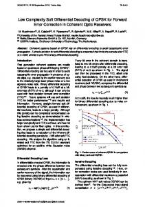
A. Finite-Length Effect In the real-world communications systems, narrow finitelength datatypes (e.g. 16-bit floating point) are used for cost and speed reasons. Therefore, the error generated by the finite-length effect usually affects the performance of the system. Matrix manipulations such as matrix inversion are very sensitive to finite-length effects, which means that as the SNR improves, the induced finite-length error will become significant compared to the noise, which in the end will dominate the BER. B. Simulation and Wordlength Selection In order to evaluate the numerical stability of different matrix manipulation methods against the finite-length effect, and to select the shortest wordlength which still supplies sufficient precision, a finite-length floating point simulator is developed. Transmission schemes consisting of different number of users (in other words, different size of channel matrices) are simulated with their performance compared. For example, for a two-user case the simulated system has four transmitting antennas and two receiving antennas using STBC with two time slots, the resulting matrix is 4 × 4. The transmitter modulates random binary data with QPSK modulation. The decoder uses the MMSE algorithm to recover the information symbols. Monte Carlo simulation is used to compute the BER/SNR curves. By default, the randomly generated channel matrices have unity power on average, and noise is added on the receiver side according to the SNR. Fig. 2, Fig. 3 and Fig. 4 show the simulation result for different matrix sizes and for the different algorithms described in this paper. The numerical representation is either a 16-bit floating point representation (6 bits of exponent and 10 bits of mantissa), or a 20-bit floating point representation (6 bits of exponent and 14 bits of mantissa). Finally, each graph has an “ideal” curve generated with the 64-bit IEEE double precision format. Although the 16-bit floating point datatype supplies enough precision for the inverse of small matrices, the finite-length error becomes significant when the size of matrix gets larger, e.g. for 8 × 8 matrix inversion, the BER performance saturates even if the SNR increases further. It can be concluded that in case 20-bit floating point is used, ABAMI can supply enough precision to the matrix inversion
−5
10
−6
10
0
5
10
15
20
25
Fig. 2. Simulation results for 4 × 4 matrix inversion. At SNR=25dB, The three 16-bit curves are above the 20-bit curves, and the “ideal” curve is at the bottom, very close to the 20-bit curves.
QPSK MMSE, 8x8 matrix
−1
10
−2
10
−3
10
ABAMI 16b QRD+BS 16b AQRD+BS 16b ABAMI 20b QRD+BS 20b AQRD+BS 20b ideal
−4
10
−5
10
−6
10
0
Fig. 3.
5
10
15
20
25
Simulation results for 8 × 8 matrix inversion.
QPSK MMSE, 16x16 matrix
−1
10
−2
10
−3
10
ABAMI 16b QRD+BS 16b AQRD+BS 16b ABAMI 20b QRD+BS 20b AQRD+BS 20b ideal
−4
10
−5
10
−6
10
0
Fig. 4.
5
10
15
20
25
Simulation results for 16 × 16 matrix inversion.
VI. C OMPARISON
OF
E XPERIMENTAL R ESULTS
A. Conceptual Hardware The latency of algorithms not only depends on the number of basic operations but also the amount of parallelism that can be exploited by parallel hardware. Therefore, in this paper, conceptual hardware is used to measure the latency of different matrix manipulation algorithms. Two hardware platforms have been investigated. One is called SOLO and it consists of one Floating Point Complex Multiply-ACcumulate (FPCMAC) unit (3 pipeline stages), one real divider (3 cycles latency). The other is called QUARTET and it contains four FPCMAC and a real divider. For the evaluation of QRD, a real valued 1/sqrt unit (5 cycles latency) is used instead of the divider. Using the Synopsys design flow and 90 nm (1.08V, low leakage) process from ST Microelectronics, SOLO consumes 22k gates while QUARTET consumes 72k gates and both can run at 500MHz. B. Comparison of Latency Based on SOLO and QUARTET, the latency of both BAMI and ABAMI for matrices of different sizes is depicted in Table III. The table shows clearly that ABAMI provides a 50% reduction of the number of cycles needed by exploiting the Alamouti sub-block structure. In Table IV, the latency of GR based QRD and our AQRD is compared. The savings from exploiting the Alamouti sub-block structure by AQRD results in a more than 50% reduction compared to QRD. Although the speed-up achieved by QUARTET against SOLO is trivial for small matrices (e.g. 4 × 4) because of the low number of operations available for parallel processing, the speed-up grows towards 400% as the size of the matrix increases. The tables also show that it is more difficult to parallelize QR than blockwise matrix inversion in programmable hardware such as a parallel FPCMAC. Note the overhead of data loads/stores is implicit here because we assume the register file is large enough and that there is a permutation unit which allows data shuffling in parallel to the computation. Size of Matrix SOLO BAMI ABAMI QUARTET BAMI ABAMI
Latency (cycles) 4 × 4 8 × 8 16 × 16 96 604 4356 54 320 2220 49 210 1216 45 152 708
TABLE III Latency (cycles) of Matrix Inversion
Size of Matrix SOLO QRD AQRD QUARTET QRD AQRD
Latency (cycles) 4 × 4 8 × 8 16 × 16 164 1384 11088 67 450 3188 142 ≈785 ≈4240 53 263 1561
TABLE IV Latency (cycles) of QRD and AQRD
VII. C ONCLUSION In this paper, we applied the BAMI (blockwise analytical matrix inversion) method to larger matrices and proposed a specialized and more efficient method (ABAMI) to compute matrix inversion for Alamouti sub-block based STBC matrices. An Alamouti QRD (AQRD) based on a variant of Givens rotation for Alamouti matrices is proposed by us to reduce the computational complexity of QRD. As shown by the comparison of the number of operations in Sec. III-B and Sec. IV-B.3, and the latency in Sec. VI-B, both the ABAMI and AQRD methods can significantly reduce the computational complexity and latency compared to BAMI and QRD using GR. As mentioned in [6], BAMI is already over 3 times faster compared to several other recent solutions ([4], [5]) with even lower hardware cost. ABAMI achieves a further speedup of 200% and also reduces the storage needed (the size of register file) by half compared to BAMI. Blockwise matrix inversion has lower latency and even slightly better numerical stability compared to the QRD based solutions. Note that all the methods presented in this paper can easily be mapped to programmable devices, which has much higher flexibility than traditional fixed-functional systolic arrays thus making it suitable for multi-standard baseband processing. VIII. ACKNOWLEDGMENT The work of J. Eilert, D. Wu and D. Liu is supported partly by the Swedish National Foundation of Strategic Research SSF. The work of D. Wang and N. Al-Dhahir is supported in part by NSF contracts CCF04-30654 and DMS05-28010. R EFERENCES [1] S. M. Alamouti, “A Simple Transmit Diversity Technique for Wireless Communications”, IEEE J. Select. Areas Commun, vol. 16, no. 8, pp 1451–1458, 1998. [2] G. H. Golub, C. F. Van Loan, “Matrix Computations, Third Edition”, The Johns Hopkins University Press, 1996. [3] W. Givens, “Computation of Plane Unitary Rotations Transforming a General Matrix to Triangular Form”, J. Soc. Indust. Appl. Math., Vol 6, No.1, 1958. ¨ [4] F. Edman, V. Owall, “Implementation of A Full Matrix Inversion Architecture for Adaptive Antenna Algorithms”, Proc. WPMC’04, 2004. [5] M. Karkooti, J. Cavallaro, C. Dick, “FPGA Implementation of Matrix Inversion Using QRD-RLS Algorithm”, Proc. 39th Asilomar Conference on Signals, Systems, and Computers, 2005. [6] J. Eilert, D. Wu, D. Liu, “Efficient Complex Matrix Inversion for MIMO Software Defined Radio”, Proc. IEEE International Symposium on Circuits and Systems, 2007. [7] A. H. Sayed, W. M. Younis, A. Tarighat, “An Invariant Matrix Structure in Multi-Antenna Communications”, IEEE Signal Processing Letters, 2005. [8] W. M. Younis, A. H. Sayed, and N. Al-Dhahir, “Efficient adaptive receivers for joint equalization and interference cancellation in multi-user space-time block-coded systems”, IEEE Transactions on Signal Processing, vol. 51, no. 11, pp. 2849–2862, Nov. 2003.