Proceeding of the 7th International Symposium on Mechatronics and its Applications (ISMA10), Sharjah, UAE, April 20-22, 2010
COMPONENT-BASED MODELING FRAMEWORK FOR MECHATRONIC SYSTEMS Ashraf Saleem Philadelphia University Mechatronics Engineering Department Amman, Jordan
[email protected]
ABSTRACT This paper presents a component-based framework for mechatronic systems modeling. The main concept of componentbased approach is to create a model for common system’s basic components, which can be reused as many times as required. These components can be then successively aggregated in order to have a model that sufficiently represents the whole system. The proposed framework is a hierarchical structure with three different layers: (1) basic components layer, (2) subsystem components layer, and (3) mechatronic system layer. The proposed framework has many advantages include: (I) reducing the development cost and time, (II) improving system maintainability and flexibility (III) enhancing system quality. A practical example is explained in order to interpret the proposed framework. 1.
INTRODUCTION
The main outcome of system modeling is to solve practical problems by creating mathematical models or equations, these equations can be utilized to analyze the system performance. From the design perspective, system modeling can assist to realize how well the system has met the design requirements and how best to modify and optimize the design as necessary. Mechatronic systems generally exhibit nonlinear characteristics due to its complex nature and the integration of different subsystems [1, 2]. To overcome the nonlinearity of the model’s governing equations, it has become a common practice to replace a non-linear model of Mechatronic systems by a linearized version which provides a reasonable description of the system dynamics around an operating point. However, this approach cannot predict the global behavior of the system which considered as important as a particular solution around the operating point [3, 4]. There are several modeling techniques that are usually used such as: black box, gray box, white box modeling and componentbased modeling. Component-based modeling approach has been used by many researchers [2, 5, and 13].
Component-based modeling approach starts by the process of identifying the components within the physical system (i.e. decomposing the system into its basic components), and then determining the linkage nature between the components when several of them are connected together. Components model are created, evaluated and validated separately. Aggregating all components’ models will formulate the whole system model. This will lead to a reduction in model complexity, an increase in their robustness, and a faster model formulation. All components should include parameters providing adaptability to different design. They can be stored in a library as validated ready-to-use models, which enable reusing. The rest of the paper is organized as follows: section 2 reviews existing modeling techniques while section 3 explains the component-based modeling technique as interpreted in this study. Section 4 explained the proposed framework for mechatronic system decomposition. Section 5 provides a practical example which helps in interpreting the proposed framework and finally section 5 concludes the paper. 2.
REVIEW OF MODELING TECHNIQUES
This section reviews and discusses the techniques normally employed in the modeling and analysis of mechatronic systems. 2.1 Black-box Modeling Black-box technique or “empirical curve fitting” is employed when only the input/output behavior of the system, and not the physical meaning of the model parameters, is of interest. The basic concept of the method is to deal with the physical system as a “black-box” with the input and output variables defined from the parameters which can be measured in a series of experiments on the system. As stated before, mechatronic systems reveal a nonlinear behavior if they considered over a wide operating range. Therefore, it is more effective to employ nonlinear modeling techniques to describe nonlinear behaviors. Nonlinear modeling techniques are essentially the regression methodology applied to the input-output
ISMA10-1
Proceeding of the 7th International Symposium on Mechatronics and its Applications (ISMA10), Sharjah, UAE, April 20-22, 2010
data sets which is regarded as nonlinear black-box structure. This approach has been employed by many researchers [6, 7]. The disadvantage of this method is the need to acquire a sufficient set of experimental test data of the system which may not be exist at the time of the design. Furthermore, this approach cannot be adopted as a general analysis or configuration for mechatronic systems since the model is created for particular components with certain parameters. Therefore, a new data collection and training procedure should be conducted if any modification on the system is applied. Finally, problems are still present particularly in the computational difficulties of the methods and validity test.
2.2 Grey-box Modeling This modeling approach is utilized when some physical insights are available, but several parameters need to be determined from test data. Grey-box modeling can be thought of as a combination of a “white” model and a “black” model. The “white” model should be established by explicitly utilizing prior knowledge and physical insights such as that on the clear nonlinear structure derived from physical laws. On the other hand, the “black” model should be used to approximate the neglected or un-measurable nonlinearities. In such a grey-box, the system will not rely entirely on artificial structures such as fuzzy logic and neural networks as seen in black-box model approximators.
Linearization process for the nonlinear model of mechatronic system has been employed by many researchers [11, 12]. They claim that linearization is valid for dynamic characteristics analysis and effective for control system stability investigation around the operating point. However, the major disadvantage for linearization is its reference to the linearization point, so that when the operating point gets further away from the linearization point, the linear model’s behavior will increasingly deviate from the behavior of the real system which will invalidate the linearization approach. 3.
COMPONENT-BASED MODELING
Component-based approach has been applied firstly in software industry over the last decade [5, 13]. The main concept of component-based approach is to create a model for the common system components, and then reuse it as many times as required. In the context of this study, a component can be defined as an entity or subsystem which designed to perform a certain functions and tasks and can be used as a building block in the design of a larger system. Hardware and software components are sharing common characteristics: (1) component is visible in some forms, (2) component can individually and completely perform one or more tasks, (3) component can set-up some relationship with other components in connections, and (4) a component can be a part of whole system or part of another component. Components share some common characteristics:
State-space modeling is considered as a typical example on greybox modeling. Basically, the model consists of a set of ordinary differential equations (ODEs) which are usually derived from the physical operating mechanism of the system. These ODEs consist of state variables and state coefficients. For example, in the case of servo-pneumatic systems the piston position and velocity, and the pressure in both chambers are the state variables, and the friction coefficients and flow rate in the valve and the chambers are the state coefficients.
a.
Completeness: the completeness of a component means that: (a) each component can individually and completely do one or more tasks (the actuator component produce force, sensor components provides certain information about the system); (b) the status of a component and its output events or functions must be clear while any input event or function of the component is active at any time. The completeness of a component establishes a limit for the minimum components into which the system can be decomposed. In other words, the completeness of a component will be a useful as how to decompose a mechatronic system into components.
b.
Connectivity: each component can set up some relationship with other components in connection; (the sensor component provides signals to the controller component),
c.
Encapsulation: is one of the basic characteristics of components. A component can encapsulate two or more basic components. This characteristic of a component provides some basic idea on how to compose basic components into a sophisticated component. It is also helpful to decompose the machine into composite components then into basic components,
d.
Reusability: a component can be used as many times as required to design a system. Furthermore, components’ designer does not need to design all parts of a component each time. When a practical component is available, it could be reused as a part of another component. That will simplify the component design, save time and costs of designing and building new components.
If the state variables are known at some time, then any plant output can be computed, at all future times, as a function of the state variables and the present and future values of the inputs. Some researchers employed state-space modeling technique to create an optimal model for mechatronic systems [8]. However, this approach suffers from many drawbacks. Firstly, this approach lacks a well-established rule for determining the state variables [9]. Secondly, estimating the state variables demands high computational process and high storage requirement, which have prevented its real-time application [10]. 2.3 Linearization of Non-linear Model Linearization techniques are commonly used in nonlinear system analyses. Most of them are based on Taylor series expansion to formulate a systematic procedure for obtaining a linear model for a nonlinear system. The operating curves of the physical system can be used to formulate the relation of the input and output variables when it is not available in mathematical form. The system with nonlinear relationships is linearized to obtain a set of linear algebraic equations which can be solved readily.
ISMA10-2
Proceeding of the 7th International Symposium on Mechatronics and its Applications (ISMA10), Sharjah, UAE, April 20-22, 2010
constraints. The beauty of this flexibility allows the system model benefit from the subsequent improvement on individual component without re-design the system model itself.
Practically, the mechatronic system can be decomposed into some subsystems or many basic components. A component or a subsystem can be reused or duplicated in the same workspace to form a system. For example, two axes servo-pneumatic systems have two valves and two actuators and different loads. In this case the valves and the actuators are copies of the valve and actuator components.
4.
3.1 Basic Components Layer The basic components layer provides the basic building blocks (components) to design and evaluate the target mechatronic system. Component models should be created and evaluated separately. These components are formulated in such a way that they can be replaced by alternative components that have the same interface specifications. The system segregation allows a reduction in model complexity and an increase in their robustness, which leads to faster model formulation. Ideally, the component manufacturers supply the component models because they are likely to have insight knowledge about their developed components. Other sources to obtain the component models could be either from component designers (modelers), i.e. derivation of a mathematical model, or experimentally (e.g. empirical models or identification). The level of model complexity for individual component is dependent upon the accuracy requirements, modeling efficiency, and time
Subsystems Layer
Basic Component Layer
PROPOSED FRAMEWORK FOR MECHATRONIC SYSTEM DECOMPOSITION
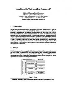
The adopted framework is a hierarchical structure with three different layers to target different categories of users (Figure 1). These layers are (1) basic components layer, (2) subsystem components layer, and (3) mechatronic system layer. This component-based framework should lead to a great potential for: (I) significantly reducing the development cost and time, (II) improving system maintainability and flexibility by allowing new components such as sensors, controllers, actuators to replace old ones, (III) enhancing system quality by allowing basic components to be developed by those who are specialized in the mechanical, electrical, electronic and control design engineering. This framework can be interpreted by the Automated Manufacturing Research Facility (AMRF) model [16].
Mechatronic System Layer
Complexity
Re-usability
The image of a component is a virtual component which implements a real component and is used in the virtual environment to compose a complete mechatronic system. The image of a component has a rectangular form and associated I/O pins, and can be thought of as a black box from the perspective of a system designer. The functions of a component are embedded within the black box. The duty of the system designer is to set the required parameters of each component, to know what functions or events will be done by a component, and the connections between the I/O pins of each component. The designer does not need to know how the functions or events will be achieved within the component, and therefore designing a mechatronic system can be achieved by simply create a block diagram of the system.
Figure 1. Conceptual framework for mechatronic system decomposition 3.2 Subsystem Components Layer Subsystem components layer builds upon the component layer. A complete system is built using the components from the previous layer. In terms of complexity, it is more complicated than the components layer, but it is not complex enough to achieve a complete task in the same way that the mechatronic system layer does. This layer is important to facilitate component development and reuse by grouping a number of device components to provide a higher-level functionality. 3.3 Mechatronic System Layer This layer corresponds to the machine/system level, which executes the detailed operation sequence in order to complete a certain job; assembly machine station is a typical example. The following section presents an example of a mechatronic system that comprises of subsystems and components. 5.
AN EXAMPLE: ASSEMBLY MACHINE STATION
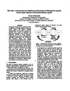
Assembly machine station is one of the practical examples that can be used to interpret the introduced framework. Figure 2 shows the machine decomposition to different levels of complexity referring to the adopted framework. This example was adapted from [17]. The advantages of the adoption of this framework are (1) the ability to reconfigure the system for
ISMA10-3
Proceeding of the 7th International Symposium on Mechatronics and its Applications (ISMA10), Sharjah, UAE, April 20-22, 2010
different applications and (2) the ability to accomplish rapid changeover from the assembly of one product to the assembly of a different product, the so-called Agility [15]. The main subsystem and basic components of the system are: (1) Robot arm: the robot arm uses three joints, which include two prismatic joints, one rotary joint, and one gripper. The prismatic joints are positioned in perpendicular to each other. While the revolute joint is attached to one prismatic and the gripper to the other. (2) Part stoppers: is a pneumatic system that consists of solenoid valve, pneumatic cylinder and a sensor. The sensor detects the pallets as they move along the conveyor, so that the robot arm can precisely place the parts on the pallets. (3) Part feeder and conveyer: the part feeder is a pneumatic air cylinder with a short stroke pushes parts forward along a guide chute. A conveyor transfers the pallet from station to station. In this system two part feeders provide the parts for the robot arms to assemble into the work piece on top of the pallet. One part feeder is located next to each robot arm. In order to establish a mathematical model of the whole system, a model of each basic component (such as valve, cylinder, gripper, and controller) should be created. The components should have the characteristics described in section 2. Then by aggregating the components properly, the model of the whole system can be attained.
6.
CONCLUSIONS
This research introduces a framework for mechatronic system decomposition into subsystem components and basic components. This framework should standardize the decomposition of complex mechatronic systems into basic components. An industrial example was explained in order to illustrate the use of the proposed framework. Component-based techniques, in general, have been used extensively in systems development due to their great potential for reducing time and cost, improving system maintainability and flexibility, and enhancing system quality.
Figure 2: Assembly machine station decomposition in different levels of complexity
Therefore, adopting this technique to model and simulate mechatronic systems will provide the following potentials: (1) component-based model is valid over the whole working range of the system. This is because of including the nonlinear phenomena without the need for linearization; (2) provide flexibility of configuration choice and direct interpretation because the system is broken down to subsystems or entities; (3) changes on the real system components can be reflected easily on the model; (4) the capability of modeling a wide variety of machines and handling different types of mechatronic systems; (5) facilitate the modeling of different complexity in order to allow for variation in future.
ACKNOWLEDGMENT The author would like to express his gratitude to Dr. J. Pu, Mr. Bill Wong, and Prof. Phillip Moore from the mechatronics research center (MRC) at De Montfort University/UK, for their support and advices to conduct this research. REFERENCES [1] T. Tutunji, M. Molhem, E. Turki "Mechatronics systems identification using an impulse response recursive algorithm." Simulation Modelling Practice and Theory 15 pp970-988, 2007.
ISMA10-4
Proceeding of the 7th International Symposium on Mechatronics and its Applications (ISMA10), Sharjah, UAE, April 20-22, 2010
[2] B. A. Hussein, “On modelling mechatronics systems - a geometrical approach” Mechatronics, Volume 10, Issue 3, 2000. [3] Masoud Khoshzaban Zavarehi, Peter D. Lawrence, Farrokh Sassani, “Nonlinear Modeling and Validation of SolenoidControlled Pilot-Operated Servovalves”, IEEE/ASME Transaction on Mechatronics, vol. 4, No. 3,1999. [4] P.T. Mo, “Modelling of Servo-controlled Pneumatic Drives—A Generalised Approach to Pneumatic Modelling and Applications in Servo- Drive Design”, PhD Thesis, Loughborough University, UK, 1989. [5] Meijler, T. D. and Nierstrasz, O., “Beyond objects: Components, Cooperative Information Systems: Current Trends and Directions”. M.P. Papazoglou and G. chlageter, eds., Academic Press, 1997. [6] S. Abedrabbo and T. Tutunji, "Identification and analysis of hydrostatic transmission system", International Journal of Advanced Manufacturing Technology, 2007. [7] A. Saleem, S. Abedrabbo, T. Tutunji. “On-line identification and control of pneumatic servo-drives via mixed reality environment. International Journal of Advanced Manufacturing Technology, 40:518–530, 2008. [8] Rolf Johansson, Anders Robertsson, Klas Nilsson, Michel Verhaegen “State-space system identification of robot manipulator dynamics” Mechatronics, Volume 10, Issue 3, Pages 403-418, April 2000. [9] Stoica, P. ; Jansson, M., “MIMO system identification: statespace and subspace approximations versus transfer function and instrumental variables”, IEEE Transactions on Signal Processing, v 48, n 11, Nov., p 3087-99, 2000. [10] Gambler, A., “Multivariable adaptive state-space control: A survey”, The 5th Asian Control Conference (IEEE Cat No.04EX904), pt 1, p 185-91 Vol.1, 2004. [11] Amir Poursamad, “Adaptive feedback linearization control of antilock braking systems using neural networks” Mechatronics, Volume 19, Issue 5, Pages 767-773, 2009. [12] Marc Rouff , “Computation of feedback laws for static linearization of nonlinear dynamical systems” Mechatronics, Volume 2, Issue 6, Pages 613-623, December 1992. [13] Pour, G. “Moving toward component-based software development approach”, Proceedings Technology of ObjectOriented Languages., p 296-300, 1998. [14] A. Saleem, “Component based Mixed reality Environment for the control and design of servo-pneumatic systems”, PhD Thesis, UK, 2006. [15] Quinn, R.D., Causey, G.C., et al., “Agile manufacturing workcell design”, IIE Transactions, Vol. 29 No. 10, pp. 9019, 1997. [16] Albus, J.S., Barbera, A.J, “A Control System for an Automated Manufacturing Research Facility”, Society of Manufacturing Engineering, Robots 8, 1984. [17] Sheng-Jen Hsieh, “Re-configurable dual-robot assembly system design, development and future directions”, an international journal of industrial robot, volume:30, Issue 3, PP 250-257, 2003.
ISMA10-5