design and implementation to composing software systems from a mixture of reusable off-the-shelf and custom-built components. Such an approach improves ...
IEEE ROBOTICS AND AUTOMATION MAGAZINE, VOL. XX, NO. 4, DECEMBER 2009
1
Component-based Robotic Engineering Part I: Reusable building blocks Davide Brugali, Member, IEEE and Patrizia Scandurra
Abstract— This article is the first of a two-part series intended as an introduction to Component-based Software Engineering (CBSE) in Robotics. In Part I, we regard a component as a piece of software that implements robotic functionality (e.g. path planning). The focus is on design principles and implementation guidelines that enable the development of reusable and maintainable software building blocks, which can be assembled to build robotic applications. In Part II, we will discuss the role of software components as architectural units of large, possibly distributed, softwareintensive robotic systems. The focus is on technologies to manage the heterogeneity of hardware, computational, and communication resources and on design techniques to assemble components into systems. Index Terms—Software Engineering, Reuse, Architecture, Component.
I. I NTRODUCTION Software for autonomous robotics systems is typically embedded, concurrent, real-time, distributed, and data intensive and must guarantee system properties, such as safety, reliability, and fault tolerance. Software requirements of robotic control applications are similar, to a large extent, to those of software systems in other domains, such as avionics, automotive, factory automation, telecommunication, and even large scale information systems. In these domains, it can be observed a strong move toward the application of software engineering principles to significantly reduce the effort to develop new software applications by promoting the systematic and routine use of existing solutions in the development of new systems. Component-Based Software Engineering (CBSE) [1], [2] is an approach that has arisen in the software engineering community in the last decade (see Sidebar: An historical overview of software reuse). It aims to shift the emphasis in system-building from traditional requirement analysis, system design and implementation to composing software systems from a mixture of reusable off-the-shelf and custom-built components. Such an approach improves software development by reducing the amount of code that has to be written by the application designer. In particular, reusing previously-existing software components greatly reduces time to test new applications. When a component is used in a large number of systems by different developers, the knowledge about the component D. Brugali and P. Scandurra are with the Department of Computer Science and Mathematics, Universita’ degli Studi di Bergamo, Dalmine, Italy e-mail: {davide.brugali, patrizia.scandurra}@unibg.it. Manuscript received xxx xx, 2009; revised xxx xx, 2009.
usage, robustness and efficiency is available in the user community. As such, software reuse promotes the development of maintainable, reliable, and affordable software systems. In Robotics there is a pressing need to regard the construction of new software applications as the composition of reusable building blocks [3]. Software reuse allows researchers to more easily keep up the pace of robotics research, since they do not have to constantly re-write each other’s code. For example, experts in motion planning could experiment new path planning algorithms for a mobile robot relying on obstacle avoidance and self-localization functionalities encapsulated in components off-the-shelf. Reuse of consolidated and shared components allows different teams to test their algorithms on common benchmarks in order to assess performance objectively. Nevertheless, software reuse and component-based development are not yet state-of-the-practice software development approaches in robotics. Today, most robotic research and development is still based on custom designed software architectures invented from scratch each time. Many valuable robotic applications are monolithic systems that have been developed to solve a specific class of problems. As a result, a huge corpus of software applications, which implement the entire spectrum of robot functionality, algorithms, and control paradigms, are potentially available in robotic research laboratories. Unfortunately, they are often not reusable even in slightly different application scenarios because they are tight to specific robot hardware, processing platforms, and communication infrastructures and because the assumptions and constraints about tasks and operational environments are hidden and hard coded in the software implementation. This situation is alleviated by an emerging consciousness in the robotic community of the role that software plays in the construction of effective, reliable, safe, and economically feasible robotic systems. During the last very few years many ideas from software engineering (modularity, information hiding, distributed middleware) have progressively been introduced in the construction of robotic software systems, to simplify their development, and to improve their quality as documented in [4] and [5]. The aim of this paper is to contribute to raise awareness of the great potential offered by state-of-the-art software engineering techniques and methods to develop complex robotic systems. The paper is structured as follows. Section II analyzes the factors that enable software reuse, such as portability, interoperability, and flexibility of software systems.
IEEE ROBOTICS AND AUTOMATION MAGAZINE, VOL. XX, NO. 4, DECEMBER 2009
2
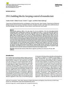
Section III introduces the concept of software component as unit of encapsulation of robotic functionality that can be composed as building block of various robotic system, presents a working example that will be used throughout the paper, and illustrates the fundamental design principle of CBSE, i.e the separation of component specification and component implementation. Section IV presents the key ingredients of a component specification, i.e. interfaces and contract, and discusses some software engineering priciples to design the specification of reusable components. Finally, Section V illustrates techniques to implement component specifications and, in particular, the concept of Component Framework as a mean to enhance robotic systems flexibility. II. R EUSABLE SOFTWARE BUILDING BLOCKS Within software engineering, a software architecture is typically defined as: ”the structure or structures of the system, which comprise software components, the externally visible properties of those components, and the relationships among them” [6]. Here components are units of implementation and represent a code-based way of considering the system. Thus, a robot software architecture describes the decomposition of the robot control system into a collection of software components, the encapsulation of functionality and control activities into components, and the flow of data and control information among components. The design or selection of the software architecture takes specifically into account non-functional requirements of a robotic software system (maintainability, portability, interoperability, scalability, etc.) that is those -ilities that characterize software quality and enable software reuse. As an example, figure 1 depicts the CLARAty [7] control architecture that partition robot capabilities into two hierarchical layers: the Decision Layer and the Functional Layer. Each layer groups software components that implements specific algorithms, such as those for task planning, navigation, locomotion, pose estimation, sensor processing, and motor control. The mapping of robot functionality to components, that is, how algorithms, data structures, synchronization and communication mechanisms are packaged together, is a crucial design step as it greatly influences the reusability of those functionality. Ideally, components embedding common robot functionality should be reusable in different robot control systems and application scenarios, and thus they should not be bounded to specific robotic hardware, software development technologies, or control paradigms. For example, a fully reusable component implementing a mobile robot navigation algorithm should be designed without implicit assumptions about the operational setting (e.g. stand alone application or distributed system), the possible use (e.g. map building or object tracking), the robot morphology (e.g. size and shape), and even its kinematic structure (e.g. number and type of wheels). In reality, designing reusable components consists in finding the best trade-off between being too specific (less reusable) and too generic (less valuable). Three aspects of a reusable
Fig. 1.
The CLARAty architecture
component are equally important: quality, technical reusability and functional reusability. The quality of a robotic software component is typically expressed in terms of its computational performance (e.g. the time required to process a video frame), efficiency (e.g. the amount of memory used to build a probabilistic roadmap), or reliability (e.g. the probability of returning a sensor measure when needed). Quality can be assessed here and now, provided that adequate metrics and benchmarks are available (e.g a standard reference image for testing different edge detection algorithms or different implementations of the same algorithm). Technical reusability of a robotic software component is mainly concerned with its degree of usability and interoperability. The source code of a software component is not usable if it is not properly documented or if the cost of its exploitation (e.g. integration with the rest of the system) is too high. In some cases, it is more convenient to design and build the component from scratch. Interoperability is the ability of two or more systems or components to exchange information and to use the information that has been exchanged. Interoperability with third-party systems can be achieved by designing welldefined component interfaces, protocols, and data exchange formats, by clearly separating component interface and implementation, and possibly by conforming the component’s specification to existing standards. From a functional point of view, reusable components can be classified with respect to application domains into two broad categories (see Figure 2) horizontal and vertical components. The term domain is used to denote or group a set of systems (e.g. mobile robots, humanoid robots) or applications (service robotics, space robotics, etc.) that exhibit similar characteristics or fulfill similar requirements. Horizontal components provide functionality to a variety of applications that may implement totally different use cases. Typical horizontal components provide system services such as interfacing to hardware devices, providing computational or communication services, or implementing mathematic func-
IEEE ROBOTICS AND AUTOMATION MAGAZINE, VOL. XX, NO. 4, DECEMBER 2009
Fig. 2.
3
The scope of reuse: horizontal vs. vertical components
tions. Vertical components capture a company, organization, or research community know-how in specific functional areas, such as kinematics, motion planning, deliberative control and address the requirements of target application domains, such as service robotics, space robotics, or humanoid robotics. It has been reported [8] that vertical components contribute the most to reuse up to 65% of any application, while horizontal components typically no more than 20%. Functional reusability requires insight into the future and a clear understanding of how robotic systems integrating reusable components will be likely to evolve. The three reusability aspects described above are equally important [9]. The highest-quality component will never be reused if the function it offers is useless. The most needed component will never be reused if it is unreliable, slow, hard to understand. The highest-quality and most needed component will never be reused if the interface is not compatible. III. C OMPONENT- BASED S OFTWARE E NGINEERING Out of the multiple definitions for software components we can find in literature, in this tutorial we adopt the one given in [2] as it illustrates the key factors that enable component reusability: “A software component is a unit of composition with contractually specified interfaces and explicit context dependencies only. A software component can be deployed independently and is subject to composition by third parties”. In this paper we illustrate design principles that mostly refer to the concepts expressed in the first sentence of this definition, i.e.e contractually specified interfaces and explicit context dependencies. The second part of this tutorial will address issues related to the components composition and deployment. Thus, in the rest of this paper, we regard components as implementation software units, which developers can reuse to develop a variety of different applications more quickly than writing all of the code from scratch for each application. We will refer to Object Oriented Technology (see Sidebar), which is not a necessary paradigm to implement components but the most convenient one. Fig. 3 shows the key ingredients to realize software components. A software component comes with a well-defined component specification, which is an abstraction from the details (data structures and operations) of its (possibly many) implementations.
Fig. 3.
A component’s key ingredients
A component specification explicitly declares which functionality (provided interfaces) are offered to its clients1 , the public obligations (contracts) with its clients in the form of various kinds of constraints (e.g. preconditions, postconditions, invariants) on how to access the functionality, and the dependencies (required interfaces)to the functionality that are delegated to other components. A component implementation, on the other hand, defines how the component supports those features and obligations in terms of a collaborative structure of realizing objects (class instances) and algorithms implementing the functionality declared in the component specification. Separating component specification from its implementation is desirable for achieving modular, interoperable, and extensible software and to allow independent evolution of client and provider components. If client code depends only on the interfaces to a component and not on the component’s implementation, a different implementation can be substituted without affecting client code. Furthermore, the client code continues to work correctly if the component implementation is upgraded to support an extended specification. CBSE defines a set of principles that help software developer to design components that are effectively reusable. We illustrate and exemplify them in the following sections. A. A working example Motion planning for autonomous mobile manipulators is a robot functionality that is realized by an integrated set of algorithms, such as collision checking, configuration sampling, and path planning. Several implementations of these algorithms are available as open source software library (see for example, MPKit [10] and MSL [11]). In the context of the EU project BRICS (http://www.best-of-robotics.org), we are currently contributing to the design of software components that offer a reusable environment to embed the most prominent motion planning algorithms found in literature [12]. In this paper, we take some of our recent results to exemplify the design principles illustrated in the following sections. In particular, we 1 We refer here to the term client to denote code invoking an operation on some component, not necessarily in a distributed environment.
IEEE ROBOTICS AND AUTOMATION MAGAZINE, VOL. XX, NO. 4, DECEMBER 2009
4
be implemented by different components, each one embedding a specific algorithm and specific internal representations of obstacles and robots (see [15] for a comprehensive overview of collision checking libraries). A. Provided and required interfaces
Fig. 4. Motion planning components interconnected by means of provided and required interfaces. A complete circle (a.k.a lollipop) represents an interface that the component provides. A half circle (a.k.a. sockets) represents an interface that the component requires. In both cases, the interface’s name is placed near the interface symbol itself. A dependency arrow comes out of the requiring socket towards the provider’s lollipop
refer to the design of four major components (see Figure 4), i.e. Cartesian Space, Configuration Space, Collision Checker, and Path Planner. Component Cartesian Space encapsulates the data structures that store the geometric representation of the robot and its surrounding environment. It provides information about object shapes and positions and geometric elaboration services, such as compute the relative position of two objects. Component Configuration Space encapsulates the data structures that define a robot’s configuration space and provides services such as sampling robot configurations, interpolating between two configurations, and measuring the distance between two configurations. Component Collision Checker checks if a given configuration is obstacle-free. It requires access to the information that define shape and position of every object in the environment. In the example depicted in Figure 4, these information are provided by Component Cartesian Space. Component Path Planner computes a robot path between a start and an end robot configuration. Typical path planning algorithms, such as Probabilistic Roadmaps [13], sample the robot configuration space and check if a given configuration is obstacle free. For this purpose, in Figure 4, the Path Planner component uses the services provided by the Configuration Space and the Collision Checker components. IV. C OMPONENT S PECIFICATION The specification of a software component is the key to its successful use as a part in a larger piece of software. In this section, we introduce interface design concepts and guidelines [14] first and then discuss some relevant aspects related to interface contracts. Interfaces are the external visible parts of the components and components interact with each other through interfaces. Interfaces support the information hiding and protect client code from changes in the component implementation. A given component may implement more than one interface and an interface may be implemented by a number of different components. For example, interface CollisionCkecking could
A component has one or more provided and/or required interfaces. The provided interfaces of a component are the set of interfaces realized by the component. They represent the contractually specified functionality that the component offers to their clients. The required interfaces, instead, specify functionality and resources that the component needs in order to perform its own functions and fulfill its own obligations to its clients. A required interface of a component denotes an explicit context2 dependency, that is a usage relationship between the component’s implementation and the implementation of those components implementing the corresponding provided interfaces. Components are interconnected to build systems by wiring together their required and provided interfaces. The diagram in Figure 4 shows provided and required interfaces of each component using the UML ball-andsocket notation. In particular, the Path Planner provides the PathPlanning interface and requires the ConfigurationSampling and CollisionChecking interfaces. This means that the Path Planner is able to plan robot paths provided that it is interconnected to two components, which are responsible for sampling valid robot configurations and checking if a given configuration is collision free. B. Service interfaces and data interfaces Interfaces can be classified in data interfaces and service interfaces. Data interface expose state information of components and make it available to its clients. Data interfaces typically contain getter/setter operations for retrieving or set values of attributes. For example (see Figure 4), interface SpaceBrowsing provides access to the internal state of component Cartesian Space and returns information about shape and position of objects located in the robot operational environment. Data interfaces may also specify attributes as abstract properties implying that the realizing component should explicitly maintain information corresponding to the type and multiplicity of the attribute and facilitate retrieval and modification of that information. If an interface declares an attribute, this does not necessarily mean that the realizing component will necessarily have such an attribute in its implementation (i.e., the attribute value may be computed by an algorithm when the get operation is invoked), only that it will appear so to external observers. This is the case of interface ConfigurationSampling which defines operations that return a valid robot configuration, i.e. a configuration defined 2 A context of use exists for each single component and contains its connections, its containment, the allocation on hardware and software resources, the usage profile, and the perceived functional and non-functional properties in the actual environment.
IEEE ROBOTICS AND AUTOMATION MAGAZINE, VOL. XX, NO. 4, DECEMBER 2009
Fig. 5. The information model of Configuration objects exchanged through components interfaces
within the boundary of the robot’s configuration space. The robot valid configurations are not individually represented within the component’s state, but are computed by various algorithms for configuration sampling and configuration interpolation. A service interface is a declaration of a set of functionality offered by a component operating mostly on the parameters that are passed to it, rather than on the attributes of the implementation. For example, interface CollisionChecking define operations whose results are mainly function of the specific robot configuration passed as parameter. This classification is not to be intended as a black-andwhite separation; it opens, rather, a spectrum of ways to define interfaces. An interface can range from a pure data interface, whose operations refer only to attributes of the components’ objects, to a command interface, which usually contains only service operations. C. Strongly-typed versus loosely-typed interfaces Components exchange data through their interface. An information model defines the structure and semantics of the data objects that are exchanged between components via a certain type of interface [16]. According to the type of their attributes, interfaces can be classified into strongly-typed and loosely-typed. Strongly-typed interfaces allow exact descriptions of exchanged data objects by means of specific types. For example (see Figure 5), interface ConfigurationSampling defines the sample() operation that returns an object of type Configuration. An attribute of the same type is defined as input parameter of the checkCollision() operation in interface CollisionChecking. Two different implementations of type Configuration may represent a manipulator configuration as a vector of joint values and a rover configuration as a three fields structure respectively. In contrast, loosely-typed define generic communication primitives, called performative, that correspond to a specific linguistic actions (e.g. query, answer, assert, define) and exchange data represented using primitive data types, such as textual strings, and structured according to standard markup languages such as XML.
5
Both approaches have pros and cons. On one hand, stronglytyped interfaces require components to commonly agree on a framework of data structure definitions and on the meaning of the operations on those structures in order to interoperate. Such a commitment leads to more efficient component implementations that are internally consistent and easier to debug but, at the same time, limits the reusability of those components, unless the information model is highly stable and widely accepted by developers. On the other hand, looselytyped interfaces leave the proper interpretation of messages to individual components. While this approach is supposed to be more flexible, because the details of a message are handled in the component implementation where specific data structures are defined, it is also more error prone and requires more manual programming [17]. D. Stateful versus stateless interfaces An interface can be either stateful or stateless. In a stateful interface, each operation invocation changes the component’s internal state and the information returned by the operation is computed differently based on the component’s state. Thus, the behavior of the exposed operations depends on the history of their previous invocations by the component’s clients. For example, operation getNextObstacle() in interface Space Browsing returns the reference to the next object in the list of obstacles. Thus, the result depends on the number of time the operation has been invoked. Typically, the client is interested in retrieving and analyzing several obstacle objects, whose identities are not relevant. For this reason, operation getNextObstacle() is defined in a stateful interface. In a stateless interface, instead, the operations’ behavior is always the same and depends only on the information supplied through their parameters. For example, operation getJoint(int robotID, int jointID) in interface Space Browsing always returns a reference to the same joint object identified by parameters robotID and jointID. This operation is conveniently defined in a stateless interface, because the client knows exactly the identity of the object to retrieve. In a stateless interface, a client component has to specify all the information related to its request at each operation invocation. This means that the client component has to keep track of the state of its interaction with the component that implements the stateless interface. On the other hand, the main advantage of a stateless interface is that operations can service many different client requests without caring about the order of the operation calls and without binding specific resources of the provider component to an individual client to keep track of its state. In contrast, stateful interfaces requires less effort in implementing client components to get the same results. Data supplied by a client (trough parameters) are accumulated between operation invocations, and therefore operations require shorter parameter lists. Stateful interfaces are, however, more complex to implement because component implementations have to manage concurrent access to the internal state by
IEEE ROBOTICS AND AUTOMATION MAGAZINE, VOL. XX, NO. 4, DECEMBER 2009
Fig. 6. The specification of components Configuration Space and Cartesian Space defines interfaces for clients with different roles (create and use)
different clients and require a means to keep track of the order of operation invocations and of their side effects on the provider components’ state. E. Different interfaces for different clients Usually, a component specification defines more than one provided interface in order to address the requirements of different clients. Two main issues need to be considered in defining the set of component interfaces: separation of concerns and completeness. Robotic software systems are typically modeled along a unique direction: the functional decomposition (or composition) of parts. The underlying assumption is that the properties of the entire system may be confined into specific components so that the system behavior is obtained through composition of well-packaged functionality. Nevertheless, there are concerns (quality factors or functionalities) that cannot be effectively specified using the concept of composition of high cohesion functional components. Such concerns relate to the software system as a whole hence crosscutting its modular structure. A typical crosscutting concern is system initialization for which each component should provide an adequate interface. For example, components Configuration Space and Cartesian Space provide interface Initializing, which allows component System Factory to initialize the boundary and constraints of the robot configuration space and the geometric representation of the robot morphology respectively. In this example, the two components define different interfaces for creating and initializing their internal state and for using their services. Interface completeness refers to the degree of usability of the functionality implemented by a component. Minimal interfaces expose the minimum set of operations that allow clients to access all common component functionality. In contrast, complete interfaces expose additional operations that simplify the use or enhance the accessibility of those functionality in specific use cases. For example, interface SpaceBrowsing define basic operations for browsing individual obstacles, but also additional operations for retrieving groups of obstacles satisfying specific conditions (e.g. their are located within a
6
certain distance from a given position). Similarly, interface CollisionChecking defines operations that simply check if a given configuration is obstacle free, but also additional operations that return complex data structures storing information about the shape and position of the contact surface. Minimal and complete interfaces are conveniently organized in a specialization hierarchy, where more complete interfaces extend minimal interfaces. Different components may implement interfaces at different level of completeness. While all component implementations will be usable by all clients, some clients will benefit from the use of operations providing a higher level of abstraction or a deeper level of accessibility. On one hand, minimal interfaces reduces the responsibilities of the provider component and are thus easier to implement. It is therefore likely that several implementations of a minimal interface are available and that developers can choose the implementation that fits at best the requirements of their client applications. In contrast, complete interfaces that exhibit unwanted complexity (in the signature, constraints, and information model) increase dependencies on implementation details leading to less reusable components. On the other one, minimal interfaces make the implementation of the client code more complicated, since the exposed operations may require to be invoked in an appropriate and intricate sequence in order to realize a certain functionality or, even worse, prevent the client to access all the needed component functionality. In contrast, complete interfaces support the development of a larger variety of client applications for specialized use cases. F. Contracts An interface specifies a contract between the component implementation and its clients. A contract can be seen as an explicit roster of mutual obligations expressed in the form of various kinds of constraints [18], such as preconditions, postconditions, invariants, and protocol specifications. The client of a component interface needs to ensure that certain preconditions are met when calling an operation. For example, the precondition of operations setStart() and setEnd() in interface PathPlanning states that the passed parameters must represent valid start and end robot configurations. Each operation in an interface specifies postconditions that will be true after its invocation is complete. For example, the computePath() operation returns a robot path that must be obstacle-free. If a precondition is not met, the operation may work improperly. If the preconditions are met and a postcondition is not met, the operation has not worked properly. Invariants describe the conditions that every component implementation must satisfy and that must not be violated by interface operations. Typical invariants state constraints on the amount of resources that an operation invocation may require, such as memory size and processing time. Protocols impose ordering restrictions on operations invocation, i.e. it specifies the set of allowable sequences of operations calls. For example, the protocol of interface
IEEE ROBOTICS AND AUTOMATION MAGAZINE, VOL. XX, NO. 4, DECEMBER 2009
Fig. 7. Flexibility among different realization of the same interface (left hand side) and flexibility within a component framework (right hand side)
PathPlanning states that operation computePath() can be invoked only when operations setStart() and setEnd() have been executed correctly. The protocol can also show the callbacks that an interface may create, events that are generated, or observers that are called. V. C OMPONENT I MPLEMENTATION Separation of component specification and implementation enables reuse of software components embedding common robotic functionality. If, for a given application domain, a coherent set of required interfaces can be defined that specify the most frequently used robot services and capabilities, and if applications in that domain are designed around those interfaces, then every component implementing compatible provided interfaces has the potentiality to be reused in those applications. The various implementations of a component may differ in non-functional characteristics (i.e. performance, maintainability, documentation quality, reliability), realizing technology (e.g. the description of the geometric space may be stored in a relational database or as collection of XML files) and even programming language (when components are build on a middleware or multi-language run-time infrastructure). A clear separation of component specification and implementation grants component developers the flexibility to improve the software quality of their components without affecting the implementation of the applications that integrate them. At the same time, application developer have the flexibility to chose the components that best meet the quality requirements of their systems. Flexibility (see left hand side of Figure 7) requires components specifications to be stable for a given domain (i.e. interfaces are standard or widely accepted in the developers community) and variability in application requirements to be embedded in component implementations. In this context, flexibility enhances component reuse in the sense that a given component implementation can be used as a black box to build different component systems provided that it meets their application requirements. Component reuse can be further enhanced if commonalities among different implementations of the same component specification are identified and properly exploited. Here stability can be defined as a component’s resilience to changes in the
7
original requirements specification [19] and refers to the internal representation of a component, which is seen as a white box (see right hand side of Figure 7). The basic assumption is that vertical components (see Section II) encapsulate functionality that are typically implemented around common entities and mechanisms, which are core aspects within the domain (e.g. the concepts of Path and Configuration) and can be represented as stable data structures and operations. Those aspects of a component implementation that are more likely to be affected by the evolution of the application domain (e.g. ) represent its variation points. In the following, we introduce the concept of component framework as a technique to clearly separate stable and variable aspects of a component implementation and illustrate variability implementation techniques that reduce the effort of developing new implementations of the same component specification. A. Component Framework A component framework is a skeleton of a component implementation that can be specialized by a component developer to produce custom components. A component framework captures commonalities among different implementations of similar components and points of variability to express the differences. As such a component framework represents a family of component implementations, which share domain-specific properties and differ for application-specific requirements. A component framework is stable if new concrete components can be derived from its design and built on its data structures and operations without changing them. Frameworks have acquired popularity in object-oriented programming [20]. Here, the interpretation of ”framework” ranges from structures of classes of cooperating objects which provide, through extension, reusable basic designs for a family of similar applications (Johnson and Foot 1988), to the more restrictive view [21] of complete high level modules which, through customization, directly result in specific applications for a certain domain. Frequently, the two views of framework, referred to as white box and black box approaches to reuse, may be simultaneously present in one framework [22]. In fact, features, which are likely to be common to most component implementations, can be offered and therefore reused as black boxes with minor changes. On the other hand, the class library accompanying the framework usually provides base classes (seen as white boxes) that can be specialized, by adding subclasses as needed, and easily integrated with the rest of the framework. An intriguing relationship exists between frameworks, design patterns, and pattern languages (see sidebar A). In a pioneering paper [23] Johnson argues that patterns document frameworks and help to ensure the correct use of framework functionalities. We take a more radical position: a pattern language – the organized collection of patterns for a certain application domain – in our view generates the framework which, thereafter, offers the elements for the pattern implementations, and it accompanies the framework through its life.
IEEE ROBOTICS AND AUTOMATION MAGAZINE, VOL. XX, NO. 4, DECEMBER 2009
Fig. 8.
8
The Configuration Space Component Framework
Any application framework, in fact, follows an evolution in time, which we call the framework life span [24]. In this life span, the basic architectural elements, which are independent from any specific application, are implemented first. Then by generalizing from concrete component implementations (the refactoring process indicated in Figure 7) the framework evolves. The generalization process consists in identifying abstractions that are recurrent across implementations of the same functionality. These abstractions can be captured by design patterns and usually consist in clusters of related classes, which have to be specialized in concrete component implementations. In fact, in its early stages the framework is mainly conceived as a white box framework , i.e. it mainly provides base classes (variation points) that can be specialized by adding subclasses that implement specific data structures and algorithms (variants). However, through its adoption in an increasing number of component implementations, the framework matures: more concrete variants which provide black box solutions for the difficult problems, as well as high level objects which represent the major abstractions found in the problem domain, become available within the framework. Figure 8 depicts the UML diagram of the Configuration Space component framework. It is the result of the refactory process of state-of-the-art motion planning libraries [12] that we are currently carry on in collaboration with the partners of the EU project BRICS. The framework represents a family of similar components that implement a common set of provided interfaces. Three of them, namely Configuration Interpolating, Configuration Sampling, Configuration Metric, provide clients (e.g. the Path Planner) with access to the component functionality. Interface CSpace Setup defines operations for component initialization and configuration. For sake of clarity, the figure shows a simplified version of these interfaces, where only the main operations are indicated.
The component framework clearly identifies stable data structures (black boxes), variation points (blue boxes), and concrete variants (red boxes). The stable entities are class Configuration and class CSpace. A configuration has one or more dimensions, one for each degree of freedom of the robotic system. The configuration space defines the domain of each configuration, represents the constraints on the values of valid configurations, and stores the set of valid configurations that have been sampled. The variation points are represented by class Interpolator, class Sampler, and class Distance Metric. They are abstract classes that define basic data structures and operations that are common to a family of similar algorithms. The component developer supplies concrete subclasses (e.g. Liner Interpolator, Uniform Sampler, Manhattan) that implement specific algorithms corresponding to possible variants within the family of similar algorithms. Class CSpace Factory has been designed according to the Prototype pattern [25]. It plays the role of ”registry” that maintains a cache of all variants implemented by the component framework. The System Factory (see Figure 6) configures the component’s functionality at initialization time by selecting a specific variant of each variation point according to given criteria passed through the CSpace Setup interface. The selection can be changed at run time and is transparent to the component’s clients, which access its functionality through the provided interfaces. B. Implementing variability Variability is managed through different component configuration mechanisms [26], which can be classified according to the binding time, i.e. the software development step when a variability is decided: • Compile-time: The variability is resolved before the program compilation (e.g., with preprocessor directives) or
IEEE ROBOTICS AND AUTOMATION MAGAZINE, VOL. XX, NO. 4, DECEMBER 2009
at compile time. Mechanisms that typically causes the variability to be resolved at compile-time are: inheritance, aggregation, parametrization, and conditional compilation. • Link-time: The variability is resolved during module or library linking (e.g., selecting different libraries with different versions of the exported operations). • Run-time : The variability is resolved during program execution. An example of late-binding techniques is Reflection. 1) Inheritance and extension: Object inheritance is used to assign base functionality to superclasses and extensions to subclasses. Subclasses may introduce new attributes, operations, or overwrite or wrap existing ones. Inheritance may be used to provide variants by separating variabilities into derived subclasses. However this means that the growing number of different variants implies a growing number of subclasses, which in many cases leads to complex inheritance hierarchies. 2) Aggregation and delegation: Aggregation is an objectoriented technique that enables an (aggregate) object to contain other objects. Aggregation may be done by value or by reference. By value means that the lifetimes of the whole and the part objects are exactly the same; they are born and die at the same time. By reference de-couples the lifetimes of the two objects. The whole may not have a part, or it may have a different part at different times. Different wholes may share the same part. De-allocating the whole will not automatically de-allocate the part. The whole can delegate the part to provide some functionality by forwarding to the part requests it can normally not satisfy. Variability can be handled by putting the standard or mandatory functionality in the delegating object and the variant functionality in the delegated object. This technique works well with optional features, but gets worse when the number of variants grows significantly requiring additional delegation classes. 3) Parameterization: Parametric types, templates, and precompiler macros are used when unbound parameters or macro expressions can be inserted in the code and later instantiated with the actual parameter or by expanding the macro. The idea of parameterized programming is to to represent reusable software as a library of parameterized components. Component behavior is determined by the values parameters are set to. Parameterization avoids code replication by centralizing code decision around a set of variables. A typical usage is to make structured data types (stacks, queues, lists, etc.) flexible and working for any kind of data by allowing setting the data type through a parameter. However, the major drawback is that parameterization strictly depends on the particular selected programming language. 4) Conditional compilation: Macro definitions given as parameters to the compiler, ifdefs statements, and recent context-aware programming languages [27] may be used at compile-time to select between different implementations in the code and therefore lead to different variants of a component. Code segments may be included or excluded from a
9
program compilation. Directives mark the varying locations in the code. The makefiles mechanism is also another way to perform a sequence of compilations and linkages at link-time depending on the makefile parameters. One benefit of this technique is the encapsulation of multiple implementations in a single module. The desired functionality is selected by defining the appropriate conditional symbols. On the other hand conditional directives do not support recursion or any other kind of looping which makes difficult to enable advanced code selection schema. Moreover, following the decisions related to a conditional code selection is also not easy. A solution to that is to interrelate directives hierarchically with a central include file as a decision unit at the top of the hierarchy. 5) Dynamic Link Libraries: Static libraries contain a set of functions that can be linked to an application after it has been compiled and loaded in the same memory space. The signatures of the functions are known to the compiled code and therefore they must remain unchanged. The implementations though can change by selecting different libraries and thus providing some kind of variability support. In contrast, Dynamic link libraries, like Microsoft ActiveX controls, can be combined with several executables in the same system at loading time trough configuration files. 6) Reflection: Reflection is the ability of a program to observe and modify its own structure and behavior. Reflection relates strongly to metaprogramming where objects in higher levels of abstraction (metalevels) are established to represent entities like operating systems, programming languages, processors, object models, etc. Reflection enables access to such metaobjects and therefore allows architecting flexible systems. Reflection is an appealing run-time variation mechanism. Reflection can be, for example, combined with the standard Java dynamic class loading in order to load modules unknown until runtime, depending on the deployment context and invoke operations on these modules. However, reflective programs are difficult to understand, to debug and to maintain. VI. C ONCLUSION In this first of a two-parts tutorial on Component-Based Robotic Engineering we have illustrated the fundamental concepts and design guidelines for the development of software building blocks that embed reusable robot functionality. The focus was on the design of individual components, on the separation of component specification and component implementation, and on the techniques that maximize component interoperability and flexibility. In the second part of this tutorial, we will discuss techniques to assemble components into large and distributed component systems and methods to derive concrete applications from a common base of domain specific reusable components. A PPENDIX A S IDEBAR : A HISTORICAL OVERVIEW OF SOFTWARE REUSE Software reuse is the use of existing software to construct new software [28]. Software reuse practice takes typically two different forms:
IEEE ROBOTICS AND AUTOMATION MAGAZINE, VOL. XX, NO. 4, DECEMBER 2009
opportunistic: the software engineer reuses pieces of software that fit the current problem. • systematic: the research and development team puts explicit effort (i.e. invests) in developing software building blocks that meet the requirements of a family of similar applications, fit into an higher level architecture, and thus can be reuse to solve a larger class of problems. Systematic reuse is generally recognized as a key technology for improving software productivity and quality. Systematic software reuse was introduced along the first COBOL compiler almost fifty years ago, when the concept of libraries was developed. The libraries allowed collections of precompiled, reusable subroutines to be linked into a program. The vision of the COBOL team was that in the course of a few years, standard libraries would be developed for different application domains, allowing developers to write high-level programs that reused most of the logic and functionality available in the libraries. This, however, has not happened; the only domain where library-based reuse has been successful is numerical analysis, where a large number of FORTRAN and C libraries are available and are used in many projects. The main reason for the failure of library-based reuse is the difficulty of encapsulating high-level functionality in subroutines. Subroutine libraries suffer from the division of procedural code and data which make up a program. The advent of object-oriented languages, starting with Simula in 1967 [29] and gaining popularity with the development of Smalltalk [30] in the eighties, introduced a new technique for reuse: the class library. Object-oriented programs are seen as structures of objects, which encapsulate state and behavior and communicate with messages; the behavior of the whole system is the result of the interactions and collaborations between the objects. The developer implements classes, which are descriptions of the state and behavior for a number of similar objects, and creates objects as instances of the classes. The class library approach, however, has not been much more successful than the subroutine libraries; most of the successful class libraries consist of simple container or collection classes which are object-oriented implementations of basic data structures. The failure of class-library reuse is partly due to the fact that class libraries commonly restricts polymorphism to work on objects which are specializations of a class supplied with that library, and that each library provides a different, incompatible version of this top-level class. As software systems continued to grow in size and complexity, the importance of design and architecture increased. Software architecture development has shifted attention from code reuse to design reuse, by giving more importance to the fundamental role that patterns of relationships between the elements of an architecture have in any design. In contrast to the class libraries approach, the structure of interconnections between classes is reused, not the classes themselves. While a large number of general methods and notations have been developed for creating and documenting designs and architectures, such as the OMG Unified Modeling Language (UML) [xx], systematic reuse of concrete architectures and designs has been possible only with the introduction of Design Patterns [25], Architectural Styles [31], and Application •
10
Frameworks [32] in the middle Nineties. Design Patterns are textual and graphical descriptions of reusable design solutions to recurrent design problems in specific application context. Design Patterns document not only the design, but also the development knowledge and expertise that lead to that design. The whole set of patterns for a specific application domain (e.g. Factory Automation [33]), together with their structuring principles represented by the network of connections among individual patterns, is called a Pattern Language, and is a design method for the domain which accompanies the software life cycle from the analysis to the final implementation. Architectural Styles describe families of architectural designs that share a set of common assumptions. An architectural style provides a specialized component vocabulary (e.g. the terms Client, Server, Application Server, etc.), a connector vocabulary (e.g. pipes, data stream, etc.) and a set of rules to build specific topology using components and connectors. An Application Framework is an integrated set of reusable and extendible software artifacts for a specific application domain. It consists of both reusable code and reusable design. This means that applications which are built using the framework are never designed and implemented from scratch; instead, the framework design and implementation are used as a starting point. More recently, in addition to Component Based Software Engineering (CBSE) [2], Software Product Lines (SPL) [34], and Model-Driven Engineering (MDE) [35] have been proposed as new software development approaches that relieve the application developer from most of the burden of designing and implementing entire applications. A SPL is a set of applications (products) that share many (structural, behavioral, etc.) commonalities and together address a particular domain. Each new application is build from the SPL repository of common software assets (e.g. requirements specification, architectural and design models, software components). The core of a SPL is the product line architecture that supports the variations reflected in the products and prescribes how software components can be assembled to derive individual products. MDE tools simplify and automate many activities associated with developing, optimizing, and deploying complex software systems. Developers use domain-specific modeling languages to build models that capture the structure, behavior, and relevant properties of their component-based systems. A new application is developed by reusing these models, customizing them according to specific application requirements, and semiautomatically generating source code using transformation engines and generators. A PPENDIX B S IDEBAR : O BJECT O RIENTED P ROGRAMMING Object Oriented Programming (OOP) consists of techniques and mechanisms to be used in structuring models and program code after the entities (objects) found in the problem domain. OOP is based on the concept of object as program unit, which encapsulates both data and algorithms. This concept
IEEE ROBOTICS AND AUTOMATION MAGAZINE, VOL. XX, NO. 4, DECEMBER 2009
11
Subtyping, which consists in defining a new class as subtype of an existing one. In the example of Figure 9, instances of class Geometric Curve can be substituted by instances of class Motion Behavior without affecting client’s code because both classes are subtypes of interface Navigable Leg. • Inheritance, which consists of deriving new classes as specializations of existing classes and therefore reusing existing code. For example, class Segment extends class Geometric Curve by reusing the same data structures (e.g. curvilinear x) but re-implementing some operations in a more efficient way (e.g. calculating the curve length). OOP is claimed to promote reuse by supporting the organization of complex data structures into hierarchies of abstraction. However, object-oriented programming suffers from some well known shortcomings. In particular, implementation inheritance creates a tight coupling between base and derived classes, which makes the evolution of the base classes difficult (the fragile base class problem). Every simple modification (e.g. changing the parameters of an operation) to the base class may cause semantic inconsistencies in the derived classes. In addition, a subclass cannot be understood without knowing how the inherited methods are implemented in its superclass. These and others shortcomings of OOP have lead to the introduction of Component-based Software Engineering, which specifically promotes the separation of component specification and component implementation. •
Fig. 9.
A class diagram in UML
distinguishes the object-oriented programming paradigm from pure procedural and functional paradigms. The code that accesses and modifies given data is confined to one location in the program and not spread, uncontrollably, throughout the program. The key ingredient of an object definition are identity, state, interface, and behavior. Take, for example, a library of path planning algorithms. An object called shortest path (its identity) could describe an obstacle-free robot path by means of attributes like the start and end robot configuration (its internal state); it could implement some operations like appendPathLeg() (its interface) that can be invoked by other objects (e.g. a path planner) and perform some computation (its behavior) like updating the end configuration. Objects with similar properties belong to the same class. In the previous example, class Robot Path defines a family of path objects that differ from each others in terms of their specific initial and end configurations, via points, and path legs connecting intermediate configurations. In other words, a class defines the common type of a set of objects, while an object is an instance of a specific class. Figure 9 depicts the classes of this example according to the graphical notation of the Unified Modeling Language (UML). OOP supports reuse of software objects by offering four basic techniques. • Composition, which consists in constructing new classes around objects of existing classes. For example, class Robot Path encapsulates two instances of class Configuration and has the responsibility to instantiate and initialize them correctly. • Parametric polymorphism, often called generic programming, which consists in writing a function or a class generically with respect the type of the values it handles. For example, the implementation of class List is generic with regards to the implementation of the list elements. Thus, it can be reused in class Robot Path to implement a collection of Navigable Leg objects.
ACKNOWLEDGMENT The authors would like to thank Herman Bruyninckx, Stefan Christen, Angelo Gargantini, Edmund Milke, Walter Nowak, Alexej Zakharov, and Azamat Shakhimardanov for their valuable comments. The research leading to these results has received funding from the European Community’s Seventh Framework Programme (FP7/2007-2013) under grant agreement no. FP7-ICT231940-BRICS (Best Practice in Robotics). R EFERENCES [1] G. T. Heineman and W. T. Councill, Component-Based Software Engineering: Putting the Pieces Together (ACM Press). Addison-Wesley Professional, June 2001. [2] C. Szyperski, Component Software: Beyond Object-Oriented Programming. Addison-Wesley Professional;, 2002. [3] A. Shakhimardanov, H. Bruyninckx, K. Nilsson, and E. Prassler. White paper: The use of reuse of hardware and software components in robot development. [Online]. Available: http://www.robotstandards.org/index.php?id=19 [4] D. Brugali, Ed., Software Engineering for Experimental Robotics, ser. Springer Tracts in Advanced Robotics. Berlin / Heidelberg: Springer - Verlag, April 2007, vol. 30. [5] D. Brugali and E. Prassler, “Software engineering for robotics,” Special Issue of the IEEE Robotics and Automation Magazine, March 2009. [6] L. Bass, P. Clements, and R. Kazman, Software Architecture in Practice. Addison Wesley, 1999. [7] I. A. Nesnas, “The claraty project: Coping with hardware and software heterogeneity,” in Software Engineering for Experimental Robotics, ser. Springer Tracts in Advanced Robotics, D. Brugali, Ed. Berlin / Heidelberg: Springer - Verlag, April 2007, vol. 30. [8] J. Poulin, Measuring Software Reuse: Principles, Practices, and Economic Models. Addison-Wesley Professional, 1996.
IEEE ROBOTICS AND AUTOMATION MAGAZINE, VOL. XX, NO. 4, DECEMBER 2009
[9] M. Ezran, M. Moriso, and C. Tully, Practical Software Reuse - the essential guide. ESSI Surprise Project book, 1998. [10] J.-C. Latombe, F. Schwarzer, and M. Saha. Mpk - motion planning kit. [Online]. Available: http://robotics.stanford.edu/ mitul/mpk/ [11] S. LaValle, P. Cheng, J. Kuffner, S. Lindemann, A. Manohar, B. Tovar, L. Yang, and A. Yershova. Msl - motion strategy library. [Online]. Available: http://msl.cs.uiuc.edu/msl/ [12] E. Milke, S. Christen, E. Prassler, and W. Nowak, “Towards harmonization and refactoring of mobile manipulation algorithms,” in Proceedings of the ICAR 2009 14th International Conference on Advanced Robotics, Munich, Germany, June 22 - 26 2009. [13] G. Sanchez and J. Latombe, “A single-query bi-directional probabilistic roadmap planner with lazy collision checking,” in Int. Symposium on Robotics Research (ISRR), 2001. [14] K. Pugh, Interface Oriented Design. The Pragmatic Programmers LLC., 2006. [15] M. Reggiani, M. Mazzoli, and S. Caselli., “An experimental evaluation of collision detection packages for robot motion planning,” in Proceecings of the IEEE/RSJ Int. Conf. on Intelligent Robots and Systems, 2002. [16] J. G. Wijnstra, “Components, interfaces and information models within a platform architecture,” in GCSE, ser. Lecture Notes in Computer Science, J. Bosch, Ed., vol. 2186. Springer, 2001, pp. 25–35. [17] A. Tost. (2005, September) Loosely typed versus strongly typed web services. IBM. [Online]. Available: http://www.ibm.com/ developerworks/webservices/library/ws-loosevstrong.html [18] B. Meyer, Object-Oriented Software Construction. Prentice Hall, 1997. [19] F. M.E. and A. A., “An introduction to software stability,” Communications of the ACM, vol. 44, no. 9, September 2001. [20] J. O. Coplien and D. Schmidt, “Frameworks and components,” in Pattern Languages of Program Design. Addison-Wesley, 1995, pp. 1–5. [21] H. Schmid, “Creating the architecture of a manufacturing framework by design patterns,” in Proceedings of OOPSLA95. SIGPLAN, ACM, 1995. [22] R. Johnson and B. Foote, “Designing reusable classes,” Journal of Object-Oriented Programming, vol. 1, pp. 22–35, 1988. [23] R. Johnson, “Documenting frameworks using patterns,” in Proceedings of OOPSLA 92, Vancouver, B. C., Canada, October 1992. [24] D. Brugali, G. Menga, and A. Aarsten, “The framework life span,” Communications of the ACM, vol. 40, no. 10, pp. 65–68, October 1997. [25] E. Gamma, R. Helm, R. Johnson, and J. Vlissides, Design Patterns: Elements of Reusable Object-Oriented Software. Addison-Wesley, Longman, Reading, MA, 1995. [26] M. Anastasopoulos and C. Gacek, “Implementing product line variabilities,” May 2001. [27] M. Rosemann and J. Recker, “Context-aware process design exploring the extrinsic drivers for process flexibility,” in BPMDS, ser. CEUR Workshop Proceedings, G. Regev, P. Soffer, and R. Schmidt, Eds., vol. 236. CEUR-WS.org, 2006. [28] W. Frakes and K. Kang, “Software reuse research: status and future,” Software Engineering, IEEE Transactions on, vol. 31, no. 7, pp. 529– 536, July 2005. [29] O. Dahl, B. Myhrhaug, and K. Nygaard, “Simula information: Common base language.” Norwegian Computing Center, Oslo, Tech. Rep., 1970. [30] A.Goldberg and D. Robson, Smalltalk80: The language and its implementation. Addison-Wesley, 1983. [31] P. Clements, F. Bachmann, L. Bass, D. Garlan, J. Ivers, R. Little, R. Nord, and J. Stafford, Documenting Software Architectures: Views and Beyond. Addison Wesley, 2003. [32] M. Fayad, R.J, and D.S., “Object-oriented application frameworks,” Communications of the ACM, vol. 40, no. 10, October 1997. [33] D. Brugali and G. Menga, “Architectural models for global automation systems,” IEEE Transactions on Robotics and Automation, vol. 18, no. 4, pp. 487–493, August 2002. [34] P. Clements and L. Northrop, Software Product Lines: Practices and Patterns. Addison-Wesley, 2002. [35] D. C. Schmidt, “Guest editor’s introduction: Model-driven engineering,” Computer, vol. 39, no. 2, pp. 25–31, Feb. 2006, printed.
12