Component-Based Software Engineering? — the Need to Link Methods and their Theories He Jifeng1?? , Xiaoshan Li2 , and Zhiming Liu1? ? ? 1
International Institute for Software Technology United Nations University, Macao SAR, China {hjf,lzm}@iist.unu.edu 2 Faculty of Science and Technology University of Macau, Macao SAR China
[email protected]
Abstract. We discuss some of the difficulties and significant issues that we need to consider when developing a formal method for component-based software engineering. We argue that to deal with the challenges, there is a need in research to link existing theories and methods of programming for effective support to component-based software engineering. We then present our initiative on a unified multi-view approach to modelling, design and analysis of component systems, emphasising the integration of models for different views. Keywords: Components, Interfaces, Contracts, Protocols, Functionality, Consistency, Composition, Refinement, Simulation.
1 Introduction The idea to exploit and reuse components to build and to maintain software systems goes back to “structured programming” in the 70s. It was a strong argument for development of object oriented methods and languages in the 80s. However, it is today’s growing complexity of systems that forces us to turn this idea into practice [5]. While component-based software development is understood to require reusable components that interact with each other and fit into system architectures, there is so far no agreement on standard technologies for designing and creating components, nor on methods of composing them. Finding appropriate formal approaches for describing components, the architectures for composing them, and the methods for componentbased software construction, is correspondingly challenging. It seems component-based programming is now in the similar situation of object-oriented programming in the 80s: My guess is that object-oriented programming will be in the 1980s what structured programming was in the 1970s. Everyone will be in favor of it. Every manufacture will promote his products as supporting it. Every manager will ? ??
???
Partly supported as a research task of E-Macao Project funded by the Macao Government. On leave from East China Normal University, Shanghai, China. The work is partially supported by the 211 Key project of the Ministry of Education, and the 973 project 2002CB312001 of the Ministry of Science and Technology of China. Corresponding author.
pay lip service to it. Everyone programmer will practice it (differently). And no one will know just what it is [32]. – T. Rentsch, September 1982 In this paper, we discuss some of the concepts and issues that are important for a formal method to support component-based software engineering (CBSE). We argue that there is a need to integrate existing theories and methods of programming. We then propose a unified multi-view modelling approach that is intended to support separation of concerns. Different concerns are described in different viewpoints of a system at different levels of abstraction, including those of the syntactic dependency among components, static behavior, dynamic behavior and interactions of components. We show how in the model to integrate a state-based model of functional behavior and an eventbased model of inter-component interactions. The state-based model is for white-box specification to support component design and the event-based model is for black-box specification used when composing components. Linking the theories will also shed light on the integration of tools, such as model checkers, theorem provers and testing tools, for system verification. An integrated approach allows knowledge sharing among different people in a component system development, such as requirement engineers and analysts, system assemblers, component designers, component certifiers and system verifiers. Different people play different roles and are only concerned with and use the models of aspects relevant to their jobs. After this introduction, we will discuss in Section 2 the concepts of components, interfaces and architectures. These are the three most primary concepts, on which people have not yet reached an agreement. In Section 3, we will give an overview about the recent frameworks for component systems modelling, and argue about the need to link methods. We will in Section 4 give an outline of the framework that is being developed at UNU-IIST, and point out its difficulties and limitations. We will conclude in Section 5 with a discussion about future work.
2 Components, Interfaces and Architectures The notions of components, interfaces and architectures are the most important, but not yet commonly defined three concepts in CBSE. This section discusses how different views on these concepts can be reconciled. 2.1 Components Looking into Oxford Advanced Learners Dictionary, we can find: A component is any part of which something is made. In software engineering, this would allow a software system to have as “components” assembly language instructions, sub-routines, procedures, tasks, modules, objects, classes, software packages, processes, sub-systems, etc3 . This definition obviously is too general for CBSE to provide anything new. To decide what is to be ruled in and what is to be 3
Notice these entities have very different natures.
ruled out, we first clarify the purposes of using “components” in software development, and then study their implications or necessary properties. As we said earlier, the widely accepted goal of component-based development is to build and maintain software systems by using existing software components, e.g. [38, 34, 29, 21, 33, 13, 8]. It is understood that the components are required to be reusable components. They must interact with each other in a system architecture [36, 4, 29, 12, 40, 33]. This goal of CBSE implies four orthogonal properties for a truly reusable component [38]: P1 P2 P3 P4
contractually specified interfaces, fully explicit context dependencies, independent deployment, third party composition.
Based on these conditions, it is argued in [20] that an assembly language instruction and software packages should not be treated as components, but classes in a class library are components. However, classes can hardly be components if we require P3 when composing components without access to the source code. On the other hand, we can lift a class to make it usable as a component, by providing a description of its required classes and methods. The usage of a component in a software system includes using it to replace an out of date component to upgrade the system or a failed component to repair the system, adding it to the system to extend the system services, or composing it into the system while the system itself is still being built. Some researchers insist on a component being reusable during dynamic reconfiguration. The implications of properties P1-P4 are different when a component is used in different applications, for different purposes or in different kinds of systems. This is the main reason why some people give more stringent definitions than others (e.g. [8, 34]). In [8], a component is defined by the following three axioms : A1 A component is capable of performing a task in isolation; i.e. without being composed with other components. A2 Components may be developed independently from each other. A3 The purpose of composition is to enable cooperation between the constituent components. These properties are in fact those required for a “sub-system” in [37]. The paper [8] argues that the three axioms further imply a number of more properties, called corollaries of components: C1 A component is capable of acquiring input from its environment and/or of presenting output to its environment. C2 A component should be independent from its environment. C3 The addition or removal of a component should not require modification of other components in the composition. C4 Timeliness of output of a component should be independent from timeliness of input.
C5 The functioning of a component should be independent of its location in a composition. C6 The change of location of a component should not require modifications to other components in the composition. C7 A component should be a unit of fault-containment. The implication of the corollaries from the axioms is only argued informally. Property C2 implies that a component has no state and this is also insisted on in [38]. This is now generally understood to be only required in some limited circumstances, such as for dynamic reconfiguration. Property C4 only applies to real-time systems and properties C5&C6 are only relevant to distributed mobile systems. We do not see why C7 is needed at all unless a component is to be used to replace another during the runtime of the system. In fact, in many applications coordinators or managers can be used to coordinate fault-prone components to achieve fault-tolerance [25]. On the other hand, it is argued in [34] that a software component itself is a static abstraction with plugs which are not only used to provide services, but also to require them. This implies that components are not usually used in isolation, but according to a software architecture that determines how components are plugged together. This in fact is the kind of component called a module in [37]. 2.2 Interfaces Although there is no consensus on what components are, all definitions agree on the importance of interfaces of components, and interfaces are for composition without the access to source code of components. This indicates that the differences are mainly reflected in decisions on what information should be included in the interface of a component. We further argue that interfaces for different usages and different applications in different environments may contain different information, and have different properties: – An interface for a component in a sequential system is obviously different from one in a communicating concurrent system. The later requires the interface to include a description of the communicating protocol while the former does not. – An interface for a component in a real-time application will need to provide the real-time constraints of services, but an untimed application does not. – Components in distributed, mobile or internet-based systems require their interfaces to include information about their locations or addresses. – An interface (component) should be stateless when the component is required to be used dynamically and independently from other components. – A service component has different features from a middleware component. Therefore, it is the interface that determines the external behavior and features of the component and allows the component to be used as a black box. Based on the above description, our framework defines the notion of an interface for a component as a description of what is needed for the component be used in building and maintaining software systems. The description of an interface must contain information about all the viewpoints among, for example functionality, behavior, protocols,
safety, reliability, real-time, power, bandwidth, memory consumption and communication mechanisms, that are needed for composing the component in the given architecture for the application of the system. However, this description can be incremental in the sense that newly required properties or view points can be added when needed according to the application. 2.3 Architecture The main concerns about programming in the small are the flow of control and the data structure. The specifications, design and verification all focus on the algorithm and the data structure of the program. For programming in the large, the major concerns are components and their consistent integration in an architectural context. The architectural design becomes a critical issue because of the important roles it plays in communication among different stakeholders, system analysis and large-scale reuse [4]. There are numerous definitions of software architecture, such as [2, 4, 29, 37]. The common basis of all of them is that an architecture describes a system as structural decomposition of the system into subsystems and their connections. Architecture Description Languages (ADLs), such as [2, 4, 29], are proposed for architecture description. The basic elements of ADLs are components and connectors. An ADL also provides rules for putting (composing) components together with connectors. They suffer from the disadvantage that they can only be understood by language experts – they are inaccessible to domain and application specialists. Informal and graphical notations, such as UML, are now also widely used by practical software developers for architecture specification [10, 33]. However, the semantic foundation for these UML-based models has not yet been firmly established. A mere structural description of a system is not enough in supporting further system analysis, design, implementation, verification, and reconfiguration. More expressive power is needed for an ADL [5]. In particular, an ADL should also support the following kinds of views: Interaction: the interaction protocol and mechanisms, Functionality and Behavior: functional services, key properties of its components (e.g. safety and reliability), Resources and Quality of Service: hardware units required, real-time, power, bandwidth, etc. These details allow analysis and critical appraisal, such as the quality of service. It is a great advantage if an architectural description supports the separation of these concerns and allows them to be consistently integrated for system analysis. One of the biggest challenges in formal CBSE is to develop a model that effectively supports the separation of the views for analysis of different concerns, while they can be consistently linked or combined in a whole system development process.
3 State of the Art of Formal Theories This section gives an overview of existing component-based models, and summarises the common requirements on component-based models.
3.1 Models of architectures Most of the early theories, such as [27, 26, 39, 1, 29], focus on modelling system architectures. All these models of architectures deal with coordinations among components, in an event-based approach. They can also be used for specification of connectors and coordinators. However, they do not go to the level of component design, implementation and deployment. This might be reason why ADLs still do not play any major role in practical software engineering. Recently, more delicate models are proposed for describing behavior of components and their coordinations, such as [3, 13]. Reo [3] is a channel-based model with synchronous communication. The composition of components (and connectors) are defined in terms of a few operators. The model is defined operationally and thus algebraic reasoning and simulation are supported for analysis. The disadvantage of this approach is that it is not clear how it can be extended to deal with other viewpoints, such as timing and resources. Also, being even-based, the model in [13] considers a layered architecture for composition, provided by connectors (glueing operations). It considers real-time constraints and scheduling analysis. The behavior of a component is defined in a form of a timed automaton. This provides a good low level model of execution of a component. However, the use of local clocks for modelling delays can hardly be said to be component-based. We need talk about a component at a higher level of granularity. The Stream Calculus [6, 7, 41] is a denotational framework, but otherwise similar to those of [3, 13] for being a channel-based model. In general a denotational model supports the notion of stepwise development by refinement and links specifications at different levels of abstraction better. With the scream calculus, Broy also proposes a multi-view modelling to include interface model, state machine model, process model, distributed system model, and data model [6, 7]. The main disadvantage of message/event based approaches is that changes of the data states of a component are not specified directly. While they are good at modelling behavior of electronic devices and communicating protocols, they are not inclined to the software engineering terminology and techniques. The relation of these models to program implementations is not clear and practical software design techniques, such as design patterns, is not well supported. These lead to difficulties in understanding the consistency between the interaction protocol and the functionality. 3.2 The need to link methods and theories The grand aim of CBSE is to support independently development of components and compositional design, analysis and verification of overall systems. To achieve this aim, it is essential that the approach provides a notation for multiview modelling, that allows separation of concerns and supports modelling and reasoning about properties at different levels of abstraction. The nature of multi-view and separation of concerns allows us to independently identify, describe and compose different correctness conditions/aspects [19] of different views of components, including syntactic interfaces, static and functional behavior, dynamic and synchronization behavior, interaction protocols, timing and resource constraints, etc. Separation is the key principle to ensure the simplicity of the model [21].
It is crucial that the model supports abstraction with information hiding so that we can develop refinement and transformation based design techniques [21, 6, 11]. This will provide a theoretical foundation for the integration of formal design techniques with practical engineering development methods. Design in this way can preserve correctness to a certain level of abstraction and support code generation that ensures certain correctness properties (i.e. being correct by construction [30]). Refinement in this framework characterises the substitutability of one component for another. It involves the substitutability of all the aspects, but we should be able to define and carry out refinement for different features separately, without violating the correctness of the other aspects. The integration of event-based simulation and state-based refinement facilitates assurance of global refinement by local refinement. Global refinement is specified as set containment of system behavior (such as the failure-divergence semantics of CSP). Global refinement is verified in a deductive approach supported possibly with support of a theorem prover. Local refinement is specified in terms of pre and post conditions of operations and verified by simulation often supported by a model checker. Also, refinement in CBSE must be compositional in order to global reasoning about the system can be done by local reasoning about the components [7]. We would also like the refinement calculus to support incremental and iterative design, analysis and verification. This is obviously important for scaling up the application of the method to large scale software development, and for the development of efficient tool support. We believe being incremental and iterative is closely related and complementary to being compositional, and important for lowering the amount of specification and verification and reducing the degree of automation [30]. To benefit the advantages of different methods for dealing with different aspects of component systems, an integration of these methods is needed so that their theories and tools are linked to ensure the consistency of the different views of a system. For example, the static functionality described by pre- and post conditions, dynamic behavior by state machines (or transition systems) and interaction protocols by traces have to be consistent. Summary A number of formal notations and theories have been well-established and proved themselves effective as tools for the treatment of different aspects of computer systems. Operational simulation techniques and model checking tools are believed to be effective for checking correctness, consistency and refinement of interaction protocols, while deductive verification and theorem provers are found better suited for reasoning about denotational functionality specification. For CBSE, analysis and verification of different aspects of correctness and substitutability can thus be carried out with different techniques and tools. However, integration of components requires the integration of the methods for ensuring different aspects of correctness and substitutability. The integration requires an underlying execution model of component software systems. A component may not have to be designed and implemented in an object-oriented framework. However, the current component technologies such as COM, CORBA, and Enterprise JavaBeans are all built upon object-oriented programming. Object programs are now widely used in applications and many of them are safety critical. This leads to the need to investigate the techniques of modelling, design and verification of object systems and the construction of component systems on underlying object systems.
Also, the unification of the theories of imperative programming and object-oriented programming is naturally achievable [16, 24, 14].
4
rCOS
At UNU-IIST, we are developing a model and calculus, called rCOS, for component and object systems. In this section, we focus on the main theme and features of this model, instead of technical details. Based on discussion the previous sections, we intend to formalize the characteristics of a component in a model with the following elements and notions which serve different purposes for different people at different stages of a system development: – interfaces: describe the structural nature of a system and are only used for checking syntactic dependencies and compositionality. They are represented in terms of signatures of service operations. – contracts: are semantic specifications of interfaces. A contract relates an interface to an application by specifying the (abstract) data model, functionality of the service operations, synchronization protocols, and other required qualities of service (QoS) depending on the application. The model also provides a definition of consistency among these views and and method for checking this consistency. A contract can be extended horizontally by adding more services, more properties (e.g. QoS). In this paper, we are only concerned with functionalities and protocols. – components: are implementations of contracts. The execution model of component is defined. The relation of a component to a contract is defined for the correctness of the component. – operations: are defined for interfaces, contracts and components so that they can be composed in different ways. – substitutability: is defined in terms of refinement which covers and relates statebased refinement and even-based simulation. – coordination: is defined as predicates on protocols to glue and manage a group of components. – class model: is used to define the data model that is more general than pure data types and makes it easier to link a contract to a component with an object-oriented implementation. Interfaces and contracts are used by assemblers to check compatibilities of components when assembling or maintaining a system. If components do not match with each other, assemblers can consider to write connectors with glue code to put them together. Connectors can sometimes be built as components. The protocols in the contracts are used to avoid deadlock when putting components together. The functional specification of the operations are used to ensure that the user (the other components) provides correct inputs and the component returns with correct outputs. The designer of a component has to ensure that the component satisfies its contract, in particular to avoid livelock and design errors. The verifier (certifier) must have access to the code of the component to verify the satisfaction of the contract by the component.
4.1 UTP: The semantic basis
rCOS is based on Hoare and He’s Unifying Theories of Programming (UTP) [18]. UTP takes an approach to modelling the execution of a program in terms of a relation between the states of the program. Here, a state of a program P is defined over a set of variables called the alphabet of the program, denoted by α(P) ( simply α when there is no confusion). Given an alphabet α, a state of α is a (well-typed) mapping from α to the value space of the alphabet. Programs as designs For an imperative sequential program, we are interested in observing the values of the input variables inα and output variables outα. We use a Boolean variable ok to denote whether a program is started properly and its primed version ok0 to represent whether the execution has terminated. The alphabet α is defined as the union inα ∪ outα ∪ {ok, ok0 }, and a design is of the form def
(p(x) ` R(x, y 0 )) = ok ∧ p(x) ⇒ ok0 ∧ R(x, y 0 )
where – p is the precondition, defining the initial states – R is the postcondition, relating the initial states to the final states in terms the of input value x and the output value y 0 . Note that some variable x is modified by a program and in this case we say x ∈ inα and the primed version x0 ∈ outα. – ok and ok0 : describe start and termination, they do not appear in expressions or assignments in program texts The design represents a contract between the “user” and the program such that if the program is started properly in a state satisfying the precondition it will terminate in a state satisfying the postcondition. A design is often framed in the form def
β : (p ` R) = p ` (R ∧ w0 = w)
where w contains all the variables in inα − β , which are the variables in in but not in β . We can use the conventional operations on programs statements for designs too. – Given two designs such that the output alphabet of P is the same as the primed version of the input alphabet of Q, the sequential composition def
P(inα1 , outα1 ); Q(inα2 , outα2 ) = ∃m · P(inα1 , m) ∧ Q(m, outα2 ) def
– Conditional choice: (D1 ¢ b ¤ D2 ) = (b ∧ D1 ) ∨ (¬b ∧ D2 ) – Demonic and angelic choice operators: def
D1 u D 2 = D1 ∨ D 2
def
D1 t D2 = D1 ∧ D2
– while b do D is defined as the weakest fixed point of X = ((D; X) ¢ b ¤ skip)
We can now define the meaning of primitive program commands as framed designs in Table 1. Composite statements are then defined by operations on designs.
command: c skip chaos x := e m(e; v)
design: [[c]]
description does not change anything, but termi{} : true ` true nates anything, including non-termination, {} : false ` true can happen side-effect free assignment; updates x {x} : true ` x0 = val(e) with the value of e m(in; out) is the signature with input [[var in, out]]; parameters in and output parameters [[in:=e]]; [[body(m)]]; [[v:=out]]; out; body(m) is the body command of [[end in, out]] the procedure/method Table 1. Basic commands as designs.
Refinement of designs The refinement relation between designs is then defined to be logical implication. A design D2 = (α, P2 ) is a refinement of design D1 = (α, P1 ), denoted by D1 v D2 , if P2 entails P1 ∀x, x0 , . . . , z, z 0 · (P2 ⇒ P1 )
where x, x0 , . . . , z, z 0 are variables contained in α. We write D1 = D2 if they refine each other. If they do not have the same alphabet, we can use data refinement. Let ρ be a mapping from α2 to α1 . Design D2 = (α2 , P2 ) is a refinement of design D1 = (α1 , P1 ) under ρ, denoted by D1 vρ D2 , if (ρ; P1 ) v (P2 ; ρ). It is easy to prove that chaos is the worst program, i.e. chaos v P for any program P. For more algebraic laws of imperative programs, please see [18]. The following theorem is the basis for the fact that the notion of designs can be used for defining the semantics of programs. Theorem 1. The notion of designs is closed under programming constructors: ((p1 ((p1 ((p2 ((p1
` R1 ); (p2 ` R2 )) = ((p1 ∧ ¬(R1 ; ¬p2 )) ` (R1 ; R2 )) ` R1 ) u (p2 ` R2 )) = ((p1 ∧ p2 ) ` (R1 ∨ R2 )) ` R1 ) t (p2 ` R2 )) = ((p1 ∨ p2 ) ` ((p1 ⇒ R1 ) ∧ (p2 ⇒ R2 ))) ` R1 ) ¢ b ¤ (p2 ` R2 )) = ((p1 ¢ b ¤ p2 ) ` (R1 ¢ b ¤ R2 ))
Linking designs with predicate transformers A widely used method for program analysis and design is the calculus of predicate transformers [9]. The link from the design calculus to the theory of predicate transformers is given by the following definition def
wp(p ` R, q) = p ∧ ¬(R; ¬q)
It gives the weakest precondition for the design p ` R to ensure the post condition q . Design p ` R is feasible iff wp(p ` R, false) = f alse, or equivalently ∀v • (p(v) ⇒ ∃v 0 • R(v, v 0 ) meaning p ` R can deliver a result whenever its execution terminates.
In [15], we show this definition of wp ensures validity of all the algebraic rules of the wp transformer. For example wp(true ` x0 = f (x), q(x)) = q[f (x)/x] assignment wp(D1 ∨ D2 , q) = wp(D1 , q) ∧ wp(D2 , q) disjunction /non-determinism
4.2 Interfaces In our framework, the notion of interface is different from that in Section 2.2. There, an “interface” is actually an interface specification and the same as the notion of contracts that we are to define in the next subsection. A primitive interface is a collection of features where a feature can be either a field or a method. We thus define a primitive interface as a pair of feature declaration sections: I = hFDec, MDeci
where FDec is a set of field declarations, denoted by I.FDec, and MDec a set of method declarations, denoted by I.MDec, respectively. A member of FDec has the form x : T where x and T represent respectively the name and type of this declared field. It is forbidden to declare two fields with the same name. A method op(in inx, out outx) in MDec declares the name op, the list of input parameters inx and the list of output parameters of the method. Each input or output parameter declaration is of the form u : U giving the name and type of the parameter. The method name together with the numbers and types of its input and output parameters forms the signature of a method. In general both inx and outx can be empty. For simplicity and without losing any generality in the theory, we assume a method has one input parameter and one output parameter and thus can be represented in the form op(in : U, out : V) by removing the key words in and out. Notice that the names of parameters are irrelevant. Thus, op(in1 : U, out1 : V) and op(in2 : U, out2 : V) are treated as the same method. Interface inheritance and hiding operations Inheritance is a useful means for reuse and incremental programming. When a component provides only part of the services that one needs or some of the provided operations are not quite suitable for the need, we may still use this component by rewriting some of the operations or extending it with some operations and attributes. Definition 1. (Interface inheritance) Let Ii (i = 1, 2) be interfaces. I1 and I2 are composable if no field of Ii is redefined in Ij for i 6= j . When they are composable, notation I2 ⊕ I1 represents an interface with the following field and method sectors def
FDec = FDec1 ∪ FDec2 def
MDec = MDec2 ∪ {op(in : U, out : V )|op ∈ MDec1 ∧ op ∈ / MDec2 }
To enable us to provide different services to different clients of a component, we allow to hide operations in an interface to make them invisible when the component is composed with certain components. Hiding operations provides the opposite effect to interface inheritance and is to be used to restrict an interface. In a graphical notation like UML, this can be achieved by the notation of generalization alone.
Definition 2. (Hiding) Let I be an interface and S a set of method names. The notation I\S denotes the interface I after removal of methods of S from its method declaration sector. def
def
FDec = I.FDec, MDec = I.MDec \ S
The hiding operator enjoys the following properties. 1. Hiding two sets of operations separately is the same as hiding all of the operations in the two set together, (I\S1 )\S2 = I\(S1 ∪ S2 ). Thus, the order in which two sets of operations are hidden is inessential too. 2. Hiding distributes among operands of interface inheritance (I ⊕ J)\S = (I\S) ⊕ (J\S)
4.3 Contract A contract gives the functional specification of an interface. Definition 1 (Contract) A contract is a pair Ctr = (I, MSpec), where 1. I is an interface, 2. MSpec maps each method op(in : U, out : V) of I to a specification of op that is a design with the alphabet def
def
inα = {in} ∪ I.FDec, outα = {out0 } ∪ I.FDec0
For a contract Ctr = (I, MSpec), we will use Ctr.I, Ctr.FDec, Ctr.MDec and Ctr.MSpec to denote respectively I, I.FDec, I.MDec and MSpec. Two contracts can be composed to extend both of them only when their interfaces are composable and the specifications of the common methods are consistent. This composition will be used to calculate the provided and required services when components are composed. Definition 2 (Composable contracts) Contracts Ctri = (Ii , MSpeci ), i = 1, 2, are composable if 1. I1 and I2 are composable, and 2. for any method op occurring in both I1 and I2 , MSpec1 (op(x : U, y : V )) = MSpec2 (op(u : U, v : V ))[x, x0 , y, y 0 /u, u0 , v, v 0 ]
In this case their composition Ctr1 kCtr2 is defined by def
def
I = I1 ⊕ I2 , MSpec = MSpec1 ⊕MSpec2
where MSpec1 ⊕MSpec2 denotes the overriding MSpec1 (op) with MSpec2 (op) if op occurs in both I1 and I2 . Notice that for the purpose of compositional reasoning, condition (2) makes the composition conservative extension and serves as a limited form of UML generalization. Based on this definition, a calculus of refinement of contracts and components is developed in [23]. In the rest of this section, we present the generalized notion of contracts and components.
4.4 Reactive contracts A contract defined in the previous subsection specifies the static functionality of a component that does not require synchronization when the operations are used. Such components are often used in the functional layer [11]. Business process and rules are, however, accomplished by invoking particular sequences of operations. This means a protocol of using the function operation must be imposed, often by composing a component in the functional layer and a component in the system layer [11]. The component then becomes reactive and only reacts to the calls of the operation that come in the right order. To describe synchronisation, we introduce two Boolean observables wait and wait0 to the alphabet of an operation op(in : U, out : V ) in a contract. A design D on such an extended alphabet is called reactive if W(D) ≡ D holds for the linking function def
W(D) = (true ` wait0 ) ¢ wait ¤ D
And we extend the specification MSpec(op) to a guarded design (α, g, D) denoted as g&D, where – g is boolean expression over I.FDec and represents the firing guard of op – D is a reactive design over α = {in, wait, ok} ∪ I.FDec ∪ {out0 , ok0 , wait0 } ∪ I.FDec0 . The semantics of a guarded design g&D is defined as (true ` wait0 ) ¢ ¬g ¤ D. The following theorem forms the theoretical basis for using reactive designs as the semantic domain of a programming language. Theorem 1 (Reactive designs are closed under programming constructors) For any design p ` R, W(p ` R) is a design. W maps a design to a reactive design: W 2 (D) ≡ W(D) If D is a reactive design, so is the g-guarded version g&D. W is monotonic: W(D1 ) v W(D2 ) iff (¬wait ⇒ (D2 ⇒ D1 )). So, all reactive designs form a complete lattice. 5. Reactive designs are closed under the conventional programming operators.
1. 2. 3. 4.
We can now formally define a reactive contract. Definition 3 (Reactive Contract) A reactive contract is tuple Ctr = (I, Init, MSpec, Prot), where – I is an interface – Init is a design that initialises the state and is of the form true ` Init(v 0 ) ∧ ¬wait0 , where Init is a predicate – MSPec assigns each operation to a guarded design (α, g, D). – Prot, called the protocol, is a set of sequences of call events. Each is of the form ?op1 (x1 ), . . . , ?opk (xk )
where ?opi (xi ) is a (receipt of) call to operation opi in I.MDec with an input value xi .
We use guard(op) to denote the guard in MSPec(op) for an operation op ∈ MDec. Notice that a contract defined in Section 4.3 can be used as the model of the static behavior of the component, and can seen as special case of reactive contract with all the guards of the operations being true, and the protocol being the whole set of sequences of the operations MDec∗ . Definition 4 (Semantics of Contracts) The dynamic behavior of Ctr is described by the triple (Prot, F(Ctr), D(Ctr)), where – the set D(Ctr) consists of the sequences of interactions between Ctr and its environment which lead the contract to a divergent state def
D(Ctr) = {h?op1 (x1 ), op1 (y1 )!, . . . , ?opk (xk ), opk (yk )!, ?opk+1 (xk+1 )i · s | ∃v, v 0 , wait0 • (Init; g1 &D1 [x1 , y1 /in1 , out01 ]; ...; gk &Dk [xk , yk /ink , out0k ])[true/ok][f alse/ok 0 ]}
where opi (yi )! represents the return event generated at the end of execution of opi with the output value yi , in1 and outi are the input and output parameters of opi , and gi &Di is the guarded design of method opi . – F(Ctr) is the set of pairs (s, X) where s is a sequence of interactions between C and its environment, and X denotes a set of methods which the contract may refuse to respond to after it has engaged all events in s rej rej1
def
= (true, false, true, false/ok, wait, ok’, wait0 )
def
= (true, false, true, true/ok, wait, ok’, wait0 )
def
F(Ctr) = {(h i, X) | ∃v 0 • Init[rej] ∧ ∀?op ∈ X • ¬guard(op)[v 0 /v]} (h?op1 (x1 ), op1 (y1 )!, . . . , ?opk (xk ), opk (yk )!i, X) | 0 ∃v • (Init; g1 &D1 [x1 , y1 /in1 , out01 ]; ∪ ...; 0 0 /v] gk &Dk [xk , yk /ink , outk ])[rej] ∧ ∀?op ∈ X • ¬guarad(op)[v (h?op1 (x1 ), op1 (y1 )!, . . . , ?opk (xk ), opk (yk )!i, X) | 0 ∃v • (Init; g1 &D1 [x1 , y1 /in1 , out01 ]; ∪ ...; 0 gk &Dk [xk , yk /ink , outk ])[rej] ∧ opk ! 6∈ X (h?op1 (x1 ), op1 (y1 )!, . . . , ?opk (xk )i, X) | 0 ∃v • (Init; g1 &D1 [x1 , y1 /in1 , out01 ]; ∪ ...; gk−1 &Dk−1 [xk−1 , yk−1 /ink−1 , out0k−1 ])[rej]; gk &Dk [xk /ink ][rej1 ] 0 ∪ {s, X) | s ∈ D(Ctr) ∧ ∀?op ∈ X • ¬gi [v /v]} F(Ctr) defines fives cases when events may be refused and thus deadlock may occur if
the environment only offers these refusals: 1. The first subset of the refusals records the cases when the operation call events ?op in X cannot occur because their guards do not hold in the initial state. 2. The second subset identifies those cases where after a sequence of calls executed, the system may reach a state where the guards of the events in X are false.
3. The third case is when the execution of an operation opk is waiting to output its result. 4. The fourth case defines the scenarios when the execution of an operation opk enters a waiting state. 5. Finally, the fifth case takes the divergent traces into account. We define the traces of a contract as those traces in the failure set def
T(Ctr) = {s | ∃X • (s, X) ∈ F (Ctr)}
which are prefix closed. Notice that the guarded designs of the operations defines a state-based model of the dynamic behavior of the component. It corresponds to a state transition system [28, 17] and it has a clear link to temporal logic approaches for analysis and verification [22, 25]. When the state space can be reduced to a finite one, the specification of the operations can be represented by a finite state machine or automaton, that model checking tools are based on. From the guarded designs, we can obtain a the model of the static behavior too. This is how a contract model combines the event-based model of the protocol, the stated based model dynamic behavior and the pre- and postcondition specification of the static behavior of a component. However, the protocol and the functional specification of the operations have to be consistent. Definition 5 (Consistency) A contract Ctr is consistent, denoted by Consistent(Ctr), if it will never enter a deadlock state if its environment interacts with it according to the protocol. That is for all h?op1 (x1 ), . . . , ?opk (xk )i ∈ Prot, wp(Init;g1 &D1 [x1 /in1 ]; . . . ; gk &Dk [xk /ink ], ¬wait ∧ ∃op ∈ MDec•guard(op)) = true
It is shown in [15] that a contract Ctr is consistent if and only if for all sequences tr in Prot
1. there is a trace s in T(Ctr) whose projection4 on operation calls s {?} equals tr, and 2. for any failure (s, X) ∈ F (Ctr), if s {?} is a prefix of tr then not all operations and operation returns are refusals, that is X 6= {?op, op! | op ∈ MDec}. The following useful properties of consistency are proved in [15]: 1. The union of consistent protocols is a consistent protocol (with respect to a specification for the operations), that is, if Ctri = (I, Init, MSPec, Proti ), i = 1, 2, are consistent, so is Ctr = (I, Init, MSPec, Prot1 ∪ Prot2 ). 2. If contract Ctr1 = (I, Init, MSPec, Prot1 ) is consistent and Prot2 ⊆ Prot1 , then contract Ctr1 = (I, Init, MSPec, Prot2 ) is consistent. This allows us to restrict the services of a component. 3. For contracts Ctri = (I, Initi , MSPeci , Prot), i = 1, 2, if Ctr1 is consistent, Init1 v Init2 , and MSPec1 (m) v MSPec2 (m), for all m ∈ I.MDec, then Ctr2 is consistent. 4
We use for the projection (or restriction) operator in general.
Therefore, for a given (I, Init, MSPec), there is more than one protocol consistent with it. We call the largest one the weakest consistent protocol, denoted as WProt(I, Init, MSPec), such that Consitent(I, Init, MSPec, Prot) ⇒ Prot ⊆ WProt(I, Init, MSPec)
The weakest consistent protocol can be directly defined as def
WProt = {h?op1 (x1 ), . . . , ?opk (xk )i|wp(Init; g1 &D1 [x1 /in1 ]; . . . ; gk &Dk [xk /ink ], ¬wait ∧ ∃op ∈ MDec • guard(op))}
We can prove that WProt is prefix closed [15]. We, for simplicity, use (I, Init, MSPec) to denote (I, Init, MSPec, WProt). Example 1. Consider a one-place buffer with an interface BI = hempty : Boolean, {put(in : Item), get(out : Item))}i
Given MSPec to assign put and get as def
def
MSPec(put) = empty&(true ` ¬empty0 ), MSPec(get) = ¬empty&(true ` empty0 ) def
With the initial condition Init = empty, we can calculate the weakest consistent protocol to be (?put, ?get)∗ which is the set of alternating sequences of put and get, starting with a put. An n-place buffer can be similarly defined. Definition 6 (Contract Refinement) Contract Ctr1 is refined by contract Ctr2 , denoted by Ctr1 v Ctr2 , if 1. Ctr2 provides no less services than Ctr1 :Ctr1 .MDec ⊆ Ctr2 .MDec 2. Ctr2 is not more likely to diverge than Ctr1 : D(Ctr1 ) ⊇ D(Ctr2 ) Ctr1 .MDec, and 3. Ctr2 is not more likely to deadlock than Ctr1 : T (Ctr1 ) ⊇ T (Ctr2 ) Ctr1 .MDec. Notice that refinement allows us to add new services. The following two theorems (see [15] for the proofs) link the notions of simulation and refinement and combine eventbased and state-based modelling. Theorem 2 (Refinement by Downwards Simulation) Let Ctri = (Ii , Initi , MSPeci ) be two contracts. Ctr1 v Ctr2 , if there exists a total mapping ρ(u, v 0 ) from the fields FDec1 of Ctr1 to the fields FDec2 of Ctr2 such that the following conditions are satisfied 1. ρ preserves the initial condition: Init2 ⇒ (Init1 ; ρ) 2. ρ preserves the guards of all operations: ρ ⇒ (guard1 (op) = guard2 (op)) for all op ∈ MDec1 . 3. The function specification of each operation by Ctr1 is preserved by Ctr2 : for each op ∈ MDec1
MSpec1 (op); ρ v ρ; MSPec2 (op) Notice that the state mapping ρ is used as a design which does not change wait.
Theorem 3 (Refinement by Upwards Simulation) Let Ctri = (Ii , Initi , MSPeci ) be two contracts. Ctr1 v Ctr2 , if there exists a surjective mapping ρ(v, u0 ) from the fields FDec2 of Ctr2 to the fields FDec1 of Ctr1 such that the following conditions are satisfied 1. ρ preserves the initial condition: (Init2 ; ρ) ⇒ Init1 2. ρ preserves the guards of all operations: ρ ⇒ (guard1 (op) = guard2 (op)) for all op ∈ MDec1 . 3. The function specification of each operation by Ctr1 is preserved by Ctr2 : for each op ∈ MDec1
MSpec2 (op); ρ w ρ; MSPec1 (op) The same results can be found about transitions systems and the temporal logic of actions [22, 25]. Theorem 4 (Completeness of simulations) If Ctr1 v Ctr2 , then there exists a contract Ctr such that 1. There is an upwards simulation from Ctr to Ctr1 . 2. There is a downwards simulation from Ctr to Ctr2 . Contract operations All the operations defined by an interface are public, i.e, they are directly accessible by the environment of the interface. We can remove cervices from a contract as we did for an interface. Definition 7 (Removing Services) Let Ctr = (I, Init, MSPec) be a contract and S a subdef set of the operations MDec, then contract Crt\S = (I\S, Init, MSPec (MDec − S)), where we use “−” for set difference. The behavior of Ctr\S is defined by D(Ctr\S) = {s | s ∈ D(Crt) ∧ s ∈ {?op, op! | op ∈ MDec − S}∗ } F (Ctr\S) = {(s, X) | (s, X) ∈ F (Crt) ∧ s ∈ {?op, op! | op ∈ MDec − S}∗ ∧ X ⊆ {?op, op! | op ∈ MDec − S}}
When a component is to be implemented, an operation can be used in the code of another. We would like to be able to remove the former from the interface but at the same the implementation of the latter method should still work without the need for any modification. To handle this problem, we introduce in this section the notion of private (or internal) methods/operations, which are not available to the public, but can be used by the component itself. For this we need to generalize the notation of contracts to general contracts. Definition 8 (General Contract) A general contract GCtr extends a contract Ctr with a set of private methods declarations PriMDec and their specification PriMSPec GCtr = (Ctr, PriMDec, PriMSPec)
The behavior of GCtr is defined to be that of Ctr.
Now we can hide a public operation in MDec of a general contract to make it internal. Definition 9 (Hiding Service) Let GCtr = (Ctr, PriMDec, PriMSPec) be a general contract, and S a subset of the public methods MDec. The restricted contract GCtr\S is defined as (Ctr\S, PriMDec ∪ S, PriMSPec ∪ MSPec S)
We are now ready to define the composition of two general contracts. Definition 10 (Composition of Contracts). Let GCtri , i = 1, 2 be two general contracts such that 1. all shared fields have the same types, 2. all shared methods have the same specification 3. the initial conditions of the two contracts are consistent, that is satisfiable. The composition GCtr1 kGCtr2 is the general contract GCtr = ((I, MSPec), PriMDec, PriMSPec)
where def
I.FDec = I1 .FDec ∪ I2 .FDec def
I.MDec = I1 .MDec ∪ I2 .MDec def
union of the fields union of the public methods
MSPec = MSpec1 ⊕ MSPec2
overriding union of the specifications
PriMDec = PriMDec1 ∪ PriMDec2
union of the private methods
def
def
PriMSPec = PriMSpec1 ⊕ PriMSPec2 overriding union of the specifications
Properties of the operations on contracts can be found in [15]. 4.5 Components and their compositions A component is an implementation of a contract. The implementation of an operation, however, may call operations of other components. Therefore, a component may optionally have a required interface as well as a provided interface and executable code. Definition 11 (Component) A component C is a tuple (I, MCode, PriMDec, PriMCode, InMDec)
where 1. I is an interface. 2. PriMDec is a set of method declarations which are private to the component. 3. The tuple (I, MCode, PriMDec, PriMCode) has the same structure as a general contract, except that the functions MCode and PriMCode map each method op in the sets I.MDec and PriMDec respectively to a guarded command of the form g −→ c, where g is called the guard, denoted as guard(op) and c is a command, denoted as body(op).
4. InMDec denotes the set of input methods which are called by public or internal methods, but not defined in MDec ∪ PriMDec. We use C.I , C.Init, C.MCode, C.PriMDec, C.PriMCode and C.InMDec to denote the corresponding parts of C. The semantics of a component is defined to be a function that given a contract for the required interface, returns a general contract calculated from the code of the operations. Definition 12 (Semantics of Components) Let InCtr be a contract such that its interface methods are the same as the required methods of C, InCtr.MDec = C.InMDec. The behavior C(InCtr) of C with respect to InCtr is the general contract ((I, MSPec), Init, PriMDec, PriMSPec)
where def
= C.FDec ∪ InCtr.FDec
I.FDec I.MDec
def
= C.MDec ∪ InCtr.MDec
def
= Φ MDec
MSPec
def
PriMSPec = Φ PriMDec def
= C.Init ∧ InCtr.Init
Init
where function Φ assign each operation in Mdec ∪ PriMDec the guarded design calculated from the code: def
Φ(op) = guard(op)&[[body(op)]] where if m ∈ InMDec is called in body(op), the specification of op assigned by InCtr is used in the calculation [15]. It is easy to show that if InCtr1 v InCtr2 , then C(InCtr1 ) v C(InCtr2 ) Definition 13 (Component Refinement) A component C1 is refined by component C2 , denoted by C1 v C2 , if C1 .MDec ⊆ C2 .MDec, C1 .InMDec ⊇ C2 .InMDec, and the contract refinement C1 (InCtr) v C2 (InCtr) holds for all the input contracts InCtr. Composition of components The most natural composition is to plug the provided operations of one component into the required operation of the other to chain these two together. Definition 14 (Chaining) Let C1 and C2 be components such that 1. none of the provided or private methods of C2 appears in C1 , 2. C1 and C2 have disjoint field declarations. The chain C1 iiC2 of C1 with C2 is the component, which has – the fields C1 FDec ∪ C2 .FDec.
– – – – –
the required operations C1 .InMDec ∪ C2 .InMDec − C1 .MDec ∩ C2 .InMDec the provide operation C1 .MDec ∪ C2 .MDec − C1 .MDec ∩ C2 .InMDec the initial condition C1 Init ∧ C2 .Init the code C1 .Code ∪ C2 .Code the private code C1 .PriCode ∪ C2 .PriCode
Theorem 5 For any given input contract InCtr def
(C1 iiC2 )(InCtr) = (C1 (InCtr1 )kC2 (InCtr2 ))\(C1 .MDec ∩ C2 .InMDec)
where def
InCtr1 = InCtr C1 .InMDec def
InCtr2 = InCtr (C2 .InMDec − C1 .MDec)kC1 (InCtr1 ) (C1 .MDec ∩ C2 .InMDec)
The chaining operator is monotonic and commutes with the hiding operator [15]. The other often used composition is disjoint parallel composition. Definition 15 (Disjoint Composition) Let C1 and C2 be components such that they do not share fields, public operations. Then C1 ⊗ C2 is defined to be the composite component which has the provided operations of C1 and C2 as its provided operations, and the required operations of C1 and C2 as its required operations: def
(C1 ⊗ C2 )(InCtr) = C1 (InCtr C1 .InMDec)kC2 (InCtr C2 .InMDec)
Obviously, chaining C1 iiC2 is the same as disjoint parallel composition C1 ⊗ C2 when the provided services of C1 are disjoint from the required services of C2 . We also allow a provided operation to call another (possibly the same) provided operation, so as to link a required a operation to a provided operation. Definition 16 (Feedback) Let C be a component and m ∈ C.MDec and n ∈ C.InMDec. C[m ,→ n] is the component such that for any InCrt def
C[m ,→ n](InCtr) = C(InCtr.MSPec ⊕ {n 7→ (g&[[c]]})\{m} C.MCode(m) = g −→ c. Notice here the design [[c]] is the weakest fixed point of a recur-
sive equation if it calls other methods [15]. Putting components together Please notice that the conditions for disjoint parallel composition can be easily checked and carried out by either assemblers or designers. When an putting two components together using the chaining composition C1 iiC2 , one may not have access to the codes. In this case, a black box specification of Ci must be given for Ci in the form of a pair of hPCtri , RCtri i of a provided (or promising) contract and a required (or relied) contract for the components Ci . They are provided by the designer who has checked to ensure Ci (RCtri ) w PCtri
In fact, in these black box specifications, it is not necessary for the specification of operations to include the guards of the operations. The guards are only used by the designers to ensure the consistency of the protocol and the functional behavior. When C1 and C2 are to be chained, we need to check to ensure the compatibility of PCtr1 and RCtr2 , i.e. PCtr1 w RCtr2 , so that the protocol in the required contract RCtr2 agrees with that in the provided protocol, and the functional designs of the operations in the provided contract PCtr1 refine those in RCtr2 . Furthermore, the components we have considered so far are passive components. Therefore, we treat sequences in the required protocol in RCtr2 as non-deterministic choices, but the provided protocol in PCtr1 as providing deterministic choice. Let Speci = hPCtri , RCtri i, i = 1, 2, be two black box specifications, PProti and RProti the provided protocol and required protocol, and MDeci and InMDeci the provided and required operations, respectively. We define def
PProt1 /RProt2 = {s|∃t1 ∈ PProt1 , t2 ∈RProt2 •(t1 (InMDec2 )[!/?] = t2 ∧ t1 (MDec1 − InMDec2 ) = s}
Definition 17 (Interaction compatibility) For a provided protocol PProt1 and a required protocol RProt2 given in the previous paragraph, we say they are compatible if PProt1 InMDec2 ⊇ RProt2 [?op/!op | op ∈ InMDec], where a sequence in the required protocol is of the form h!op1 (x1 ), . . . , !opk (xk )i and !opi (xi ) is the call out event5 to operation op. Furthermore, when they are compatible, we define the (largest) provided protocol after the provided operations are plugged in the required operations def
PProt1 iiRProt2 = PProt1 /RProt2
Example 2. For the one-place buffer, the provided protocol is (?put, ?get)∗ . Assume a producer requires to interact with the buffer to place items into the buffer only three times. The required protocol would be {h!put, !put, !puti}. It is compatible with the provided protocol, and the protocol (?put, ?get)∗ /{h!put, !put, !puti} = {h!get, !get, !geti}. So a consumer that can be composed in must have such a required protocol. When we have a number of components requiring services from following PProt1 , the chaining compositions can be done (compatibility checking too) one by one PProt1 iiRProt2 ii . . . iiRProtk
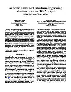
The black box specifications of components are in fact the interfaces in UML. They represent the static structural dependency among components as illustrated in Figure 1, which is from the example in [23]. For general system assembly, the model of components needs to be extended by adding the notion of ports to represent the Service Access Points (SAPs) [35]. Each port is attached with a pair of provided and required interfaces specified by their contracts hPCtr, RCtri, either can be optionally empty. We require that interfaces at different 5
It is different from op(y)! which is the return of the method op.
CustomerService
LocateParcel ()
DispatchParcel ()
GIS IParcelInfo where()
IParceLoc
MLS
GTS
ISomeInterface
CarrierSystem
Fig. 1. Static dependency among components
ports are independent. For interaction between two components, a binding has to be established between the required interface at a port of one component and a compatible provided interface at a port of another. This extension allows us to refine a component by adding ports. 4.6
Active components and connectors
The components (and contracts) we have studied so far are only passive components. When a provided service is called (according to the protocol), the component starts to execute and during the execution it may call services of other components. In general a component may be active (i.e. an actor in the sense of ROOM [35]) and have its own control and once it is started it can execute its internal actions, call services of other components, and wait to be called by other components. For purely active components, we can simply give the specification of the required contracts, including the protocol. The sequences in the protocol do not have to be non-deterministic choices in general. However, it is always safe to assume the worst case, i.e. the choice over input (namely method calls) is non-deterministic. Otherwise, the failure set must be given to describe when a choice is in the refusal set. For a more general active component the provided and required operations may be tightly related and it is not always possible to separate the provided protocol and required protocol by projections. For example, an active producer that uses the buffer in Example 2 only produces the next item after receiving an acknowledgement of the receipt of the previous one from the consumer. The protocols of the producer Prd and the consumer Con are given respectively as def
def
Prd = (!put, ?ack)∗ , Con = (!get, !ack)∗
Again, we can introduce ports into the mode of active components to represent independently defined interfaces that allows components to be connected in arbitrary configuration.
If we changed P rd to a pair of provided and required protocols by projections, we would have the provided protocol (!put)∗ and the required protocol (?ack)∗ . With these, we would not have been able to check deadlock freedom when composing it with the producer and the buffer. We believe composing this kind of active element with gray box specifications will require the full power of a theory of concurrency, such as a process algebra (CSP or CCS) or automata theory. In fact, most of the existing models adopt such a gray box specification approach, e.g. [2, 6, 3, 13] Connectors are often treated as first class elements in component-based architecture description languages. In our framework, the simple connectors are defined by the operations of chaining, disjoint parallel composition and hiding. More general connectors are defined as predicates of protocols of the form C(Prot1 , . . . , Protk , Prot), where Prot1 , . . . , Protk can be seen as roles that are mapped to components’ protocols and Prot can be seen as the glue which is the resulting protocol [2]. We call C a connector if the roles are to be linked to the required protocols of components and the resulting protocol is linked to the provided protocol of a component. C is a coordinator or manager if the roles are to be linked to the provided protocols of components and the resulting protocol is used as a provided protocol (i.e. linked to a required protocol). Connectors and coordinators for passive components are often simple. More complicated coordinators and glues can be defined for general active components. Again the need of writing complicated glue codes would push the users away from using component-based development. 4.7 Component-based and object-oriented methods In most books on component-based design in the UML framework, e.g. [10, 31], a components is taken as a family of collaborating objects (or class at the level of templates or styles) without being formally defined. Some papers, e.g. [6, 3], are critical to objectorientation and think that objects or classes are not composable and thus cannot be treated as objects. To some extent, this is true as objects or classes do not specify their required interfaces. On the other hand, all the existing component technologies, such as JavaBeans, EJB, .NET and COM, are based on object-oriented methods. Therefore, it is useful to investigate the integration of the models of components and objects. In our framework, we can take a class and translate it to primitive components easily by calculating the required methods from the code of the class methods. However, in general, a component in our proposed model can be realized by a family of collaborating classes. Therefore, for a component C, we treat the interface methods of C and the protocol as the specification of the use cases of the component and the components in environment of C as the actors of these use cases. The design and implementation of this component can then be carried out in a UML-based object-oriented framework. The types of the fields in interfaces and components can be classes. The classes and their associations form the information (data) model. This model can be represented as a UML class diagram and formalized as class declaration in rCOS [16, 14, 24]. The implementation of a contract in a component is based on the implementation of the class model. Also, for example UML2.0, a port of a component is realized by a class too (a port in an active component is realized by an active class). The component-based part
of rCOS presented here and its object-oriented part in [16, 14, 24] form a consistent combination.
5 Conclusion and Future Work We have discussed the basic concepts of components and argued for the need to link methods and their theories for programming. The link will go in two dimensions. In the horizontal direction, we need the integration of theories of state-based functional refinement [18], event-based interaction simulation, real-time [17, 25, 13], fault-tolerance [25], security, mobility and general QoS. In the vertical dimension, we need to link the theories of domain and requirements analysis, system construction by assembly of components, component construction, and component deployment. So far most models focus on the theories of interfaces and coordination models to support system construction by composing components. The link of these theories and model to software technology for component construction is still weak. We have provided some initial results towards this direction in rCOS. More work needed in the areas of component-based domain and requirements analysis and component deployment. In the horizontal direction, it is still a long way to deal with general QoS issues. Another challenge is the combination of synchronous communication and asynchronous communication. This could be done by adding message queues at the end of the receiving components or allowing shared fields in components. However, it is not clear whether there is any better way at a higher level of abstraction. We have presented the ongoing research on rCOS to support this argument. We realize the tradeoff between the simplicity of the model required for the support to CBSE and the expressiveness of the model. While linking methods will help to ease the difficulties by localising a method to a stage of the development, the need to develop sophisticated ‘glueware’ to coordinate components in applications is one reason why the saving from using “off-the-shelf” components is sometimes not as great as anticipated. If general active components and coordinators among them have to be all covered, the formal method and theory of CBSE cannot be expected to be simpler than those established for general concurrent and distributed systems. On the other hand, linking methods and their theories is useful for general software and system engineering. Acknowledgement We would like to thank Chris George, Liu Xiaojian, Chen Xin and Rodrigo Ramos for their comments on earlier versions of the paper.
References 1. R. Allen. A Formal Approach to Software Architecture. PhD thesis, Carnegie Mellon, School of Computer Science, 1997. 2. R. Allen and D Garlan. A formal basis for architectural connection. ACM Transactions on Software Engineering and Methodology, 6(3):213 – 249, 1997.
3. F. Arbab. Reo: A channeled based coordination model for components composition. Mathematical Structures in Computer Science, 14(3):329–366, 2004. 4. L. Bass, P. Clements, and R. Kazman. Software Architecture in Practice. Addison-Wesley, 1999. 5. G. Beneken and U. Hammerschall et al. Componentware - sate of the art 2003. Background Paper for Understanding Components Workshop of the CUE Initiative, 2003. 6. M. Broy. Multi-view modeling of software systems. In Z.Liu and J. He, editors, Mathematical Frameworks for Component Software: Models for Analysis and Synthesis. World Scientific, to appear. 7. M. Broy and K. Stølen. Specification and Development of Interactive Systems: FOCUS on Streams, Interfaces, and Refinement. Springer, 2001. 8. M.R.V. Chaudron and E. de Jong. Components are from Mars. In Proc. 15 IPDPS 2000 Workshops on Parallel and Distributed Processing, Lecture Notes In Computer Science; Vol. 1800, pages 727 – 733, 2000. 9. E.W. Dijkstra. A Discipline of Programming. Prentece-Hall, INC, 1976. 10. D. D’Souza and A.C. Wills. Objects, Components and Framework with UML: The Catalysis Approach. Addison-Wesley, 1998. 11. Hartmut Ehrig, Werner Damm, J¨org Desel, Martin Große-Rhode, Wolfgang Reif, Eckehard Schnieder, and Engelbert Westk¨amper, editors. Integration of Software Specification Techniques for Applications in Engineering, Priority Program SoftSpez of the German Research Foundation (DFG), Final Report, volume 3147 of Lecture Notes in Computer Science. Springer, 2004. 12. D. Garlan, R.T. Monroe, and D. Wile. Acme: Architectural description of component-based systems. In G.T. Leavens and M. Sitaraman, editors, Foundations of Component-Based Systems, pages 47–68. Cambridge University Press, 2000. 13. G. G¨ossler and J. Sifakis. Composition for component-based modeling. Science of Computer Programming, 55(1-3), 2005. 14. J. He, Z. Liu, and X. Li. rCOS: A refinement calculus for object systems. Technical Report UNU-IIST Report No 322, UNU-IIST, P.O. Box 3058, Macau, March 2005. 15. J. He, Z. Liu, and X. Li. A theory of contracts. Technical Report UNU-IIST Report No 327, UNU-IIST, P.O. Box 3058, Macau, July 2005. 16. J. He, Z. Liu, X. Li, and S. Qin. A relational model of object oriented programs. In Proceedings of the Second ASIAN Symposium on Programming Languages and Systems (APLAS04), Lecture Notes in Computer Science 3302, pages 415–436, Taiwan, March 2004. Springer. 17. T. Henzinger, Z. Manna, and A. Pnueli. Temporal proof methodologies for real-time systems. In Proceedings of the 8th ACM Annual Symposium on Principles of Programming Languages, pages 269–276, U.S.A, 1991. ACM Press. 18. C.A.R. Hoare and J. He. Unifying theories of programming. Prentice-Hall International, 1998. 19. Tony Hoare. The verifying compiler: A grand challenge for computer research. Journal of the ACM, 50(1):63–69, 2003. 20. J.P. Holmegaard, J. Knudsen, P. Makowski, and A.P. Ravn. Formalization in component based development. In Z.Liu and J. He, editors, Mathematical Frameworks for Component Software: Models for Analysis and Synthesis. World Scientific, to appear. 21. D. Hybertson. A uniform component modeling space. Informatica, 25:475–482, 2001. 22. L. Lamport. Specifying Systems: The TLA+ Language and Tools for Hardware and Software Engineers. Pearson Education, Inc., 2002. 23. Z. Liu, J. He, and X. Li. Contract-oriented development of component software. In Proc. 3rd IFIP International Conference on Theoretical Computer Science.
24. Z. Liu, J. He, and X. Li. rCOS: Refinement of component and object systems. Invited Talk at 3rd International Symposium on Formal Methods for Component and Object Systems. To Appear in Lecture Notes of Computer Science, 2005. 25. Z. Liu and M. Joseph. Specification and verification of fault-tolerance, timing and scheduling. ACM Transactions on Languages and Systems, 21(1):46–89, 1999. 26. D.C. Luckham and J. Vera. An event-based architecture definition language. IEEE Transactions on Software Engineering, 21(9):717–734, 1995. 27. J. Magee, N. Dulay, S. Eisenbach, and J. Kramer. Specifying distributed software architectures. In Proc. of 5th European Software Engineering Conference (ESEC95), pages 137–153. Springer-Verlag, 1995. 28. Z. Manna and A. Pnueli. The Temporal Logic of Reactive and Concurrent Systems: Specification. Springer-Verlag, New York, 1991. 29. N. Medvidovic and R.N. Taylor. A classification and comparison framework for software architecture description languages. IEEE Transactions on Software Engineering, 26(1):70– 93, 2000. 30. A. Pnueli. Looking ahead. Workshop on The Verification Grand Challenge February 21–23, 2005 SRI International, Menlo Park, CA. 31. R. Pooley and P. Steven. Using UML: Software Engineering with Objects and Component. Addison-Wesley, 1999. 32. T. Rentsch. Object-oriented programming. SIGPLAN Notices, 17(2):51, 1982. 33. R. Roshandel, B. Schmerl, N. Medvidovic, D. Garlan, and D. Zhang. Understanding tradeoffs among different architectural modeling approaches. In Proceedings of the Fourth Working IEEE/IFIP Conference on Software Architecture (WICSA04). 34. J.-G. Schneider and O. Nierstrasz. Components, scripts and glue. In L. Barroca, J. Hall, and P. Hall, editors, Software Architectures Advances and Applications, pages 13 – 25. Springer, 1999. 35. B. Selic, G. Gullekson, and P.T. Ward. Real-Time object-oriented modeling. Wiley, 1994. 36. M. Shaw and D. Garlan. Software Architectures: Perspectives on an Emerging Discipline. Prentice Hall, 1996. 37. I. Sommerville. Software Engineering (6th Edition). Addison-Wesley, 2001. 38. C. Szyperski. Component Software: Beyond Object-Oriented Programming. AddisonWesley, 1997. 39. R.N. Taylor, N. Medvidovic, K.M. Anderson, E. J. Whitehead Jr., J.E. Robbins, K.A. Nies, P. Oreizy, and D.L. Dubrow. A component- and message-based architectural style for gui software. IEEE Transactions on Software Engineering, 22(6):390 – 406, 1996. 40. A. van de Hoek, M. Rakic, R. Roshandel, and N. Medvidovic. Taming architecture evolution. In Proceedings of the 6th European Software Engineering Conference (ESEC) and the 9th ACM SIGSOFT Symposium on the Foundations of Software Engineering (FSE-9), 2001. 41. M. Wirsing and M. Broy. Algebraic state machines. In T. Rus, editor, Proc. 8th Internat. Conf. Algebraic Methodology and Software Technology, AMAST 2000. LNCS 1816, pages 89–118. Springer, 2000.