Jun 19, 2000 ... A John Deere ILLUSTRUCTION® Manual ..... John Deere Engine Model—4045
and 6068 Engines ..... 544H Loader, TC 54H Tool Carrier.
POWERTECH 4.5L & 6.8L Diesel Engines ®
Base Engine
COMPONENT TECHNICAL MANUAL
For complete service information also see: 4.5 L and 6.8 L Diesel Engines—Level 4 Electronic Fuel Systems CTM170 with Bosch VP44 Pump . . . . . . . . . . . . . . . . . ® POWERTECH 4.5 L and 6.8 L Diesel CTM207 Engines—Mechanical Fuel Systems. . . . . . . CTM77 Alternators and Starting Motors . . . . . . . . . . OEM Engine Accessories. . . . . . . . . CTM67 (English Only) POWERTECH®
Deere Power Systems Group CTM104 (19JUN00) LITHO IN U.S.A.
ENGLISH
Introduction Forward This manual is written for an experienced technician. Essential tools required in performing certain service work are identified in this manual and are recommended for use. This manual (CTM104) covers only the base engine. It is one of three volumes on 4.5 L and 6.8 L engines. The following two companion manuals cover fuel system repair, operation and diagnostics: • CTM170—Level 4 Electronic Fuel Systems with Bosch VP44 Pump • CTM207—Mechanical Fuel Systems CTM207 covers the fuel systems formerly included in CTM104. Other manuals will be added in the future to provide additional information on electronic fuel systems as needed. A complete set of all three manuals covering the 4.5 L and 6.8 L engines can be procured by ordering CTM350 Binder Set. Live with safety: Read the safety messages in the introduction of this manual and the cautions presented throughout the text of the manual. This is the safety-alert symbol. When you see this symbol on the machine or in this manual, be alert to the potential for personal injury. Use this component technical manual in conjunction with the machine technical manual. An application listing in Section 01, Group 001 identifies product-model/component type-model relationship. See
the machine technical manual for information on component removal and installation, and gaining access to the components. Information is organized in sections and groups for the various components requiring service instruction. At the beginning of each group are summary listings of all applicable essential tools, service equipment and tools, other materials needed to do the job, service parts kits, specifications, wear tolerances, and torque values. Before beginning repair on an engine, clean the engine and mount on a repair stand. (See Section 2, Group 010.) This manual contains SI Metric units of measure followed immediately by the U.S. customary units of measure. Most hardware on these engines is metric sized. Some components of this engine may be serviced without removing the engine from the machine. Refer to the specific machine technical manual for information on components that can be serviced without removing the engine from the machine and for engine removal and installation procedures. Read each block of material completely before performing service to check for differences in procedures or specifications. Follow only the procedures that apply to the engine model number you are working on. If only one procedure is given, that procedure applies to all the engines in the manual. CALIFORNIA PROPOSITION 65 WARNING Diesel engine exhaust and some of its constituents are known to the State of California to cause cancer, birth defects and other reproductive harm.
DPSG,OUO1004,2767 –19–18MAY00–1/1
CTM104 (19JUN00)
POWERTECH 4.5 L & 6.8 L Diesel Engines 061900
PN=2
Introduction
John Deere Dealers The changes listed below make your CTM obsolete. Repair, operation and diagnostics on 4.5L and 6.8 L diesel engines is now covered in three manuals. Discard CTM104 dated 12OCT98 and replace with the following new manuals: • CTM104 4.5 L and 6.8 L Diesel Engines—Base Engine • CTM207 4.5 L and 6.8 L Diesel Engines— Mechanical Fuel Systems • CTM170 4.5 L and 6.8 L Diesel Engines—Level 4 Electronic Fuel System with Bosch VP44 Pump
located in procedure for inspection and cleaning of cylinder block. • Revised procedure for measuring cylinder liner standout (height above block). • Revised procedure for installing cylinder liners in block. SECTION 02—GROUP 040 (Crankshaft, Main Bearings and Flywheel)
• Updated engine model designation chart. • Updated engine application charts.
• Revised procedure and specifications for removal and installation of vibration damper. • Revised procedure for removal and installation of front oil seal and wear sleeve. • Revised procedure for installation of flywheel. • Revised procedure and specifications for installation of flywheel housing. • Added procedure for removal and installation of crankshaft timing wheel on engines with Bosch VP44 fuel injection pump.
SECTION 01—GROUP 002 (Fuels Lubricants and Coolants)
SECTION 02—GROUP 050 (Camshaft, Balancer Shafts and Timing Gear Train)
• Updated engine oil and coolant application guidelines.
• Revised idler gear end play specifications. • Updated timing gear backlash specifications. • Revised procedure for removal and installation of balancer shafts. • Revised idler gear bushing and idler gear shaft specifications. • Revised procedure for installation of upper idler shaft in front plate. • Revised procedure for installation of camshaft. • Revised procedure for installation of timing gear cover. • Revised procedure for installation of crankshaft front wear sleeve and oil seal.
Also, copy this page listing changes and route through your Service Department. SECTION 01—GROUP 001 (Engine Identification)
SECTION 02—GROUP 010 (Engine Rebuild) • Updated engine lifting procedure and safety precautions. • Updated sealant application guidelines. • Added engine break-in procedure. SECTION 02—GROUP 020 (Cylinder Head and Valves) • Revised rocker arm support torque specifications.
SECTION 02—GROUP 060 (Lubrication System) SECTION 02—GROUP 030 (Cylinder Block, Liners, Pistons and Rods) • Updated procedure for determining piston-to-liner clearance. • Added sealant requirements and torque specifications for plugs and caps in cylinder block,
• Revised procedure for removal and installation of oil filter base. • Revised procedure for removal and installation of oil cooler assembly. • Revised oil pan drain plug specifications.
DPSG,OUO1004,1108 –19–07OCT99–1/2
CTM104 (19JUN00)
POWERTECH 4.5 L & 6.8 L Diesel Engines 061900
PN=3
Introduction SECTION 02—GROUP 070 (Cooling System) • Added procedure for removal and installation of water manifold/thermostat cover on 6010 Series Tractors. • Revised torque specification for water pump pulley. • Revised procedure for installation of fan assembly. • Revised procedure for installation of fan drive assembly. • Added procedure for removal and installation of cold start advance switch. SECTION 02—GROUP 080 (Air Intake and Exhaust System) • Revised turbocharger lube line torque specifications. • Added procedure for removal and installation of ether start aid.
NOTE: Fuel system theory of operation has been moved to Section 03, Group 130 in two other technical manuals: CTM207—Mechanical Fuel Systems and CTM170—Level 4 Electronic Fuel Systems with Bosch VP44 Pump. SECTION 04—GROUP 150 (Observable Diagnostics and Tests) • Base engine observable tests and diagnostics is covered in this new section/group. • Added dynamometer test procedure and specifications.
NOTE: Fuel system testing and diagnostics has been moved to Section 04, Group 150 in two other technical manuals: CTM207—Mechanical Fuel Systems and CTM170—Level 4 Electronic Fuel Systems with Bosch VP44 Pump.
SECTION 02—GROUP 090 (Fuel System) SECTION 5 (Tools and Other Materials)
NOTE: Repair procedures for fuel systems has been moved to Section 02, Group 090 in two other technical manuals: CTM207—Mechanical Fuel Systems and CTM170—Level 4 Electronic Fuel Systems with Bosch VP44 Pump. SECTION 02—GROUP 100 (Starting and Charging Systems) • Starting and charging systems are now covered in this new section/group.
• All essential tools, service tools, dealer fabricated tools and other materials listed throughout this manual are consolidated in this section for ease of reference. SECTION 6 (Specifications) • All repair, test and diagnostic specifications listed throughout this manual are consolidated in this section for ease of reference.
SECTION 03—GROUP 120 (Base Engine Operation) • Base engine theory of operation is covered in this new section/group.
DPSG,OUO1004,1108 –19–07OCT99–2/2
CTM104 (19JUN00)
POWERTECH 4.5 L & 6.8 L Diesel Engines 061900
PN=4
Introduction
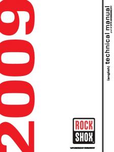
3/4 Right Front View
POWERTECH is a registered trademark of Deere & Company
CTM104 (19JUN00)
–UN–23NOV97 RG7637
RG7639
–UN–23NOV97
3/4 Left Rear View
–UN–23NOV97
3/4 Right Rear View
RG7638
RG7636
–UN–23NOV97
POWERTECH 4.5 L Engine
3/4 Left Front View
DPSG,OUO1004,129 –19–15MAY98–1/1
POWERTECH 4.5 L & 6.8 L Diesel Engines 061900
PN=5
Introduction
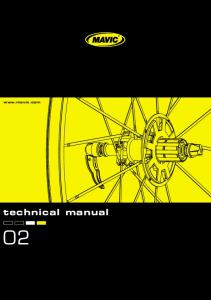
3/4 Right Rear View
POWERTECH is a registered trademark of Deere & Company
CTM104 (19JUN00)
–UN–23NOV97 RG7642
RG7643
–UN–23NOV97
3/4 Left Front View
–UN–23NOV97
3/4 Right Front View
RG7640
RG7641
–UN–23NOV97
POWERTECH 6.8 L Engine
3/4 Left Rear View
DPSG,OUO1004,130 –19–15MAY98–1/1
POWERTECH 4.5 L & 6.8 L Diesel Engines 061900
PN=6
Contents 01
SECTION 01—General Information Group 000—Safety Group 001—Engine Identification Group 002—Fuels, Lubricants and Coolants 02
SECTION 02—Repair and Adjustments Group 010—Engine Rebuild Group 020—Cylinder Head and Valves Group 030—Cylinder Block, Liners, Pistons and Rods Group 040—Crankshaft, Main Bearings and Flywheel Group 050—Camshaft, Balancer Shafts and Timing Gear Train Group 060—Lubrication System Group 070—Cooling System Group 080—Air Intake and Exhaust System Group 090—Fuel System Group 100—Starting and Charging Systems
03
04
SECTION 03—Theory of Operation Group 120—Base Engine Operation
05
SECTION 04—Diagnostics Group 150—Observable Diagnostics and Tests SECTION 05—Tools and Other Materials Group 170—Repair Tools and Other Materials Group 180—Diagnostic Service Tools Group 190—Dealer Fabricated Service Tools
06
SECTION 06—Specifications Group 200—Repair and General OEM Specifications Group 210—Diagnostic Specifications
INDX
All information, illustrations and specifications in this manual are based on the latest information available at the time of publication. The right is reserved to make changes at any time without notice. COPYRIGHT 2000 DEERE & COMPANY Moline, Illinois All rights reserved A John Deere ILLUSTRUCTION Manual Previous Editions Copyright 1996, 1998
CTM104 (19JUN00)
i
POWERTECH 4.5 L & 6.8 L Diesel Engines 061900
PN=1
Contents 01
02
03
04
05
06
INDX
CTM104 (19JUN00)
ii
POWERTECH 4.5 L & 6.8 L Diesel Engines 061900
PN=2
01
Section 01
General Information Contents Page
Group 000—Safety . . . . . . . . . . . . . . . . . . . .01-000-1 Group 001—Engine Identification Engine Model Designation. . . . . . . . . . . . . . . .01-001-1 Engine Serial Number Plate Information . . . . .01-001-2 OEM Engine Option Code Label . . . . . . . . . . .01-001-3 Engine Application Charts . . . . . . . . . . . . . . . .01-001-4 Group 002—Fuels, Lubricants and Coolants Diesel Fuel . . . . . . . . . . . . . . . . . . . . . . . . . . .01-002-1 Lubricity of Diesel Fuel . . . . . . . . . . . . . . . . . .01-002-1 Engine Break-In Oil . . . . . . . . . . . . . . . . . . . .01-002-2 Diesel Engine Oil . . . . . . . . . . . . . . . . . . . . . .01-002-3 Extended Diesel Engine Oil Service Intervals. . . . . . . . . . . . . . . . . . . . . . . . . . . .01-002-3 Alternative and Synthetic Lubricants . . . . . . .01-002-4 Mixing of Lubricants . . . . . . . . . . . . . . . . . . . .01-002-4 OILSCAN, OILSCAN Plus and COOLSCAN . . . . . . . . . . . . . . . . . . . . . . .01-002-5 Grease . . . . . . . . . . . . . . . . . . . . . . . . . . . . . .01-002-6 Diesel Engine Coolant Recommendations. . . .01-002-7 Engine Coolant Specifications . . . . . . . . . . . . .01-002-8 Testing Diesel Engine Coolant . . . . . . . . . . .01-002-11 Replenishing Supplemental Coolant Additives (SCAs) Between Coolant Changes . . . . . . . . . . . . . . . . . . . . . . . . . .01-002-12 Operating in Warm Temperature Climates . .01-002-13 Flush and Service Cooling System . . . . . . . .01-002-14 Disposing of Coolant . . . . . . . . . . . . . . . . . . .01-002-15
CTM104 (19JUN00)
01-1
POWERTECH 4.5 L & 6.8 L Diesel Engines 061900
PN=1
Contents 01
CTM104 (19JUN00)
01-2
POWERTECH 4.5 L & 6.8 L Diesel Engines 061900
PN=2
Group 000
Safety 01 000 1
Handle Fluids Safely—Avoid Fires When you work around fuel, do not smoke or work near heaters or other fire hazards.
–UN–23AUG88
Store flammable fluids away from fire hazards. Do not incinerate or puncture pressurized containers. Make sure machine is clean of trash, grease, and debris.
TS227
Do not store oily rags; they can ignite and burn spontaneously. Avoid Fires
DX,FLAME –19–29SEP98–1/1
Handle Starting Fluid Safely Starting fluid is highly flammable.
–UN–18MAR92
Keep all sparks and flame away when using it. Keep starting fluid away from batteries and cables.
TS1356
To prevent accidental discharge when storing the pressurized can, keep the cap on the container, and store in a cool, protected location. Do not incinerate or puncture a starting fluid container. Store Safely
DX,FIRE3 –19–16APR92–1/1
CTM104 (19JUN00)
01-000-1
POWERTECH 4.5 L & 6.8 L Diesel Engines 061900
PN=11
Safety
Service Cooling System Safely Explosive release of fluids from pressurized cooling system can cause serious burns.
TS281
–UN–23AUG88
Shut off engine. Only remove filler cap when cool enough to touch with bare hands. Slowly loosen cap to first stop to relieve pressure before removing completely.
Cooling System
DX,RCAP –19–04JUN90–1/1
Prevent Battery Explosions Keep sparks, lighted matches, and open flame away from the top of battery. Battery gas can explode.
–UN–23AUG88
Never check battery charge by placing a metal object across the posts. Use a voltmeter or hydrometer. Do not charge a frozen battery; it may explode. Warm battery to 16°C (60°F).
TS204
01 000 2
Battery Explosions
DX,SPARKS –19–03MAR93–1/1
CTM104 (19JUN00)
01-000-2
POWERTECH 4.5 L & 6.8 L Diesel Engines 061900
PN=12
Safety 01 000 3
Prepare for Emergencies Be prepared if a fire starts. Keep a first aid kit and fire extinguisher handy.
TS291
–UN–23AUG88
Keep emergency numbers for doctors, ambulance service, hospital, and fire department near your telephone.
First Aid Kit
DX,FIRE2 –19–03MAR93–1/1
CTM104 (19JUN00)
01-000-3
POWERTECH 4.5 L & 6.8 L Diesel Engines 061900
PN=13
Safety
Handling Batteries Safely
Always remove grounded (-) battery clamp first and replace it last.
TS204
Never check battery charge by placing a metal object across the posts. Use a voltmeter or hydrometer.
–UN–23AUG88
CAUTION: Battery gas can explode. Keep sparks and flames away from batteries. Use a flashlight to check battery electrolyte level.
CAUTION: Sulfuric acid in battery electrolyte is poisonous. It is strong enough to burn skin, eat holes in clothing, and cause blindness if splashed into eyes. Avoid the hazard by: 1. Filling batteries in a well-ventilated area. 2. Wearing eye protection and rubber gloves. 3. Avoiding breathing fumes when electrolyte is added. 4. Avoiding spilling or dripping electrolyte. 5. Use proper jump start procedure.
1. Flush your skin with water. 2. Apply baking soda or lime to help neutralize the acid. 3. Flush your eyes with water for 15—30 minutes. Get medical attention immediately. If acid is swallowed: 1. Do not induce vomiting. 2. Drink large amounts of water or milk, but do not exceed 2 L (2 quarts). 3. Get medical attention immediately.
–UN–23AUG88
If you spill acid on yourself:
TS203
01 000 4
WARNING: Battery posts, terminals, and related accessories contain lead and lead compounds, chemicals known to the State of California to cause cancer and reproductive harm. Wash hands after handling.
DPSG,OUO1004,2758 –19–11MAY00–1/1
CTM104 (19JUN00)
01-000-4
POWERTECH 4.5 L & 6.8 L Diesel Engines 061900
PN=14
Safety 01 000 5
Avoid High-Pressure Fluids Escaping fluid under pressure can penetrate the skin causing serious injury. –UN–23AUG88
Avoid the hazard by relieving pressure before disconnecting hydraulic or other lines. Tighten all connections before applying pressure.
If an accident occurs, see a doctor immediately. Any fluid injected into the skin must be surgically removed within a few hours or gangrene may result. Doctors unfamiliar with this type of injury should reference a knowledgeable medical source. Such information is available from Deere & Company Medical Department in Moline, Illinois, U.S.A.
X9811
Search for leaks with a piece of cardboard. Protect hands and body from high pressure fluids. High-Pressure Fluids
DX,FLUID –19–03MAR93–1/1
Wear Protective Clothing Wear close fitting clothing and safety equipment appropriate to the job.
–UN–23AUG88
Prolonged exposure to loud noise can cause impairment or loss of hearing.
Operating equipment safely requires the full attention of the operator. Do not wear radio or music headphones while operating machine.
TS206
Wear a suitable hearing protective device such as earmuffs or earplugs to protect against objectionable or uncomfortable loud noises. Protective Clothing
DX,WEAR –19–10SEP90–1/1
CTM104 (19JUN00)
01-000-5
POWERTECH 4.5 L & 6.8 L Diesel Engines 061900
PN=15
Safety
Service Machines Safely
–UN–23AUG88
Tie long hair behind your head. Do not wear a necktie, scarf, loose clothing, or necklace when you work near machine tools or moving parts. If these items were to get caught, severe injury could result.
TS228
Remove rings and other jewelry to prevent electrical shorts and entanglement in moving parts.
Moving Parts
DX,LOOSE –19–04JUN90–1/1
Work In Ventilated Area
–UN–23AUG88
Engine exhaust fumes can cause sickness or death. If it is necessary to run an engine in an enclosed area, remove the exhaust fumes from the area with an exhaust pipe extension. If you do not have an exhaust pipe extension, open the doors and get outside air into the area
TS220
01 000 6
Engine Exhaust Fumes
DX,AIR –19–17FEB99–1/1
CTM104 (19JUN00)
01-000-6
POWERTECH 4.5 L & 6.8 L Diesel Engines 061900
PN=16
Safety 01 000 7
Work in Clean Area Before starting a job:
–UN–18OCT88
Clean work area and machine. Make sure you have all necessary tools to do your job. Have the right parts on hand. Read all instructions thoroughly; do not attempt shortcuts.
T6642EJ
• • • •
Clean Work Area
DX,CLEAN –19–04JUN90–1/1
Remove Paint Before Welding or Heating Avoid potentially toxic fumes and dust.
–UN–23AUG88
Hazardous fumes can be generated when paint is heated by welding, soldering, or using a torch. Do all work outside or in a well ventilated area. Dispose of paint and solvent properly.
TS220
Remove paint before welding or heating: • If you sand or grind paint, avoid breathing the dust. Wear an approved respirator. • If you use solvent or paint stripper, remove stripper with soap and water before welding. Remove solvent or paint stripper containers and other flammable material from area. Allow fumes to disperse at least 15 minutes before welding or heating.
Toxic Fumes
DX,PAINT –19–03MAR93–1/1
CTM104 (19JUN00)
01-000-7
POWERTECH 4.5 L & 6.8 L Diesel Engines 061900
PN=17
Safety
Avoid Heating Near Pressurized Fluid Lines
TS953
–UN–15MAY90
Flammable spray can be generated by heating near pressurized fluid lines, resulting in severe burns to yourself and bystanders. Do not heat by welding, soldering, or using a torch near pressurized fluid lines or other flammable materials. Pressurized lines can be accidentally cut when heat goes beyond the immediate flame area.
Flammable Spray
DX,TORCH –19–03MAR93–1/1
Illuminate Work Area Safely
–UN–23AUG88
Illuminate your work area adequately but safely. Use a portable safety light for working inside or under the machine. Make sure the bulb is enclosed by a wire cage. The hot filament of an accidentally broken bulb can ignite spilled fuel or oil.
TS223
01 000 8
Illuminate Work Area Safely
DX,LIGHT –19–04JUN90–1/1
CTM104 (19JUN00)
01-000-8
POWERTECH 4.5 L & 6.8 L Diesel Engines 061900
PN=18
Safety 01 000 9
Use Proper Lifting Equipment Lifting heavy components incorrectly can cause severe injury or machine damage.
TS226
–UN–23AUG88
Follow recommended procedure for removal and installation of components in the manual.
Use Proper Lifting Equipment
DX,LIFT –19–04JUN90–1/1
Construct Dealer-Made Tools Safely
–UN–01JUL97
Faulty or broken tools can result in serious injury. When constructing tools, use proper, quality materials and good workmanship.
LX1016749
Do not weld tools unless you have the proper equipment and experience to perform the job.
Construct Dealer-Made Tools Safely
DPSG,OUO1004,899 –19–19MAY99–1/1
CTM104 (19JUN00)
01-000-9
POWERTECH 4.5 L & 6.8 L Diesel Engines 061900
PN=19
Safety
Practice Safe Maintenance Understand service procedure before doing work. Keep area clean and dry. Never lubricate, service, or adjust machine while it is moving. Keep hands, feet , and clothing from power-driven parts. Disengage all power and operate controls to relieve pressure. Lower equipment to the ground. Stop the engine. Remove the key. Allow machine to cool. Securely support any machine elements that must be raised for service work. Keep all parts in good condition and properly installed. Fix damage immediately. Replace worn or broken parts. Remove any buildup of grease, oil, or debris.
–UN–23AUG88
On self-propelled equipment, disconnect battery ground cable (-) before making adjustments on electrical systems or welding on machine.
TS218
On towed implements, disconnect wiring harnesses from tractor before servicing electrical system components or welding on machine. Keep Area Clean
DX,SERV –19–17FEB99–1/1
Use Proper Tools Use tools appropriate to the work. Makeshift tools and procedures can create safety hazards.
–UN–08NOV89
Use power tools only to loosen threaded parts and fasteners. For loosening and tightening hardware, use the correct size tools. DO NOT use U.S. measurement tools on metric fasteners. Avoid bodily injury caused by slipping wrenches.
TS779
01 000 10
Use Proper Tools
Use only service parts meeting John Deere specifications.
DX,REPAIR –19–17FEB99–1/1
CTM104 (19JUN00)
01-000-10
POWERTECH 4.5 L & 6.8 L Diesel Engines 061900
PN=20
Safety 01 000 11
Dispose of Waste Properly
–UN–26NOV90
Improperly disposing of waste can threaten the environment and ecology. Potentially harmful waste used with John Deere equipment include such items as oil, fuel, coolant, brake fluid, filters, and batteries.
Do not pour waste onto the ground, down a drain, or into any water source.
TS1133
Use leakproof containers when draining fluids. Do not use food or beverage containers that may mislead someone into drinking from them.
Recycle Waste
Air conditioning refrigerants escaping into the air can damage the Earth’s atmosphere. Government regulations may require a certified air conditioning service center to recover and recycle used air conditioning refrigerants. Inquire on the proper way to recycle or dispose of waste from your local environmental or recycling center, or from your John Deere dealer.
DX,DRAIN –19–03MAR93–1/1
Live With Safety
TS231
–19–07OCT88
Before returning machine to customer, make sure machine is functioning properly, especially the safety systems. Install all guards and shields.
Safety Systems
DX,LIVE –19–25SEP92–1/1
CTM104 (19JUN00)
01-000-11
POWERTECH 4.5 L & 6.8 L Diesel Engines 061900
PN=21
Safety 01 000 12
CTM104 (19JUN00)
01-000-12
POWERTECH 4.5 L & 6.8 L Diesel Engines 061900
PN=22
Group 001
Engine Identification 01 001 1
Engine Model Designation John Deere Engine Model—4045 and 6068 Engines John Deere engine model designation includes number of cylinders, displacement in liters, aspiration, user code, and applicable code. For example: 4045TF150 Engine 4 ............................. 4.5 .......................... T ............................ F ............................ 1 ............................. 50 ........................... Aspiration Code D ............................ T ............................ H ............................ User Factory Code AP .......................... CQ ......................... DW ......................... E ............................ F ............................ FF .......................... FG .......................... FM ......................... H ............................ KV .......................... L ............................. LA .......................... LV .......................... N ............................ P ............................ RW ......................... T ............................ T8 .......................... YC .......................... Z ............................ Model Designation 1 or 2 ..................... Application Code 50 or above ...........
Number of cylinders Liter displacement Aspiration code User code Internal engine configuration type POWERTECH application code Naturally aspirated Turbocharged and Air-to-Coolant Aftercooled Turbocharged and Air-to-Air Aftercooled Saltillo (Mexico) S.L.C. Horizontina (Brazil) John Deere Davenport Works John Deere Ottumwa Works OEM (Outside Equipment Manufacturers) Kernersville Deere-Hitachi (North Carolina) Goldoni (Italy) Marine Engines John Deere Harvester Works John Deere Knoxville (Tennesee) John Deere Werke Mannheim (Germany) John Deere Werke Mannheim (Germany) (Engines with Bosch VP44 Injection Pump) John Deere Augusta, Georgia John Deere Des Moines Works Saltillo/Monterrey (Mexico) John Deere Waterloo Tractor Works John Deere Dubuque Works Cameco (Deere) (Louisiana) John Deere Jialian Harvester Co. Limited (China) John Deere WERKE Zweibrucken (Germany) Indicates different internal engine components POWERTECH code for specific application
POWERTECH is a registered trademark of Deere & Company
CTM104 (19JUN00)
RG,01,DT7028 –19–08OCT99–1/1
01-001-1
POWERTECH 4.5 L & 6.8 L Diesel Engines 061900
PN=23
Engine Identification
Engine Serial Number Plate Information
–UN–11NOV97
IMPORTANT: The engine serial number plate (A) can be easily destroyed. Before “hot tank” cleaning the block, remove the plate. Engine Serial Number (B) Each engine has a 13-digit John Deere engine serial number identifying the producing factory, engine model designation, and a 6-digit sequential number. The following is an example:
RG7778
Engine Application Data (C)
RG9060
–UN–16MAR98
T04045T000000 T0 ........................... Factory producing engine 4045T ..................... Engine model designation 000000 ................... Sequential serial number Factory Code (Engine Manufacturer) T0 ........................... Dubuque, Iowa CD .......................... Saran, France PE .......................... Torreon, Mexico Engine Model Designation 4045T ..................... Definition explained previously. (See ENGINE MODEL DESIGNATION earlier in this group. Sequential Number 000000 ................... 6-digit sequential serial number
Dubuque Engine Serial Number Plate
The second line of information on the serial number plate identifies the engine/machine or OEM relationship. See ENGINE APPLICATION CHARTS later in this group.
–UN–16MAR98
Coefficient of Absorption (D) — (Saran-Built Engines Only)
A—Engine Serial Number Plate B—Engine Serial Number C—Engine Application Data D—Coefficient of Absorption (Saran Engines Only)
RG9061
The second line of information on Saran serial number plate also contains the coefficient of absorption value for smoke emissions.
–UN–16MAR98
Saran Engine Serial Number Plate
RG9062
01 001 2
Torreon Engine Serial Number Plate
RG,01,DT7029 –19–26APR00–1/1
CTM104 (19JUN00)
01-001-2
POWERTECH 4.5 L & 6.8 L Diesel Engines 061900
PN=24
Engine Identification 01 001 3
OEM Engine Option Code Label
NOTE: Before “hot tank” cleaning, ensure that option codes are recorded elsewhere.
CD30433
Always provide option code information and engine base code when ordering repair parts. A listing of option codes is given in Parts Catalogs and Operator’s Manuals.
–UN–10MAY95
An option code label is secured to the top of the valve cover and identifies the factory installed options on each OEM engine to ensure correct parts acquisition.
DPSG,OUO1004,482 –19–07NOV98–1/1
CTM104 (19JUN00)
01-001-3
POWERTECH 4.5 L & 6.8 L Diesel Engines 061900
PN=25
Engine Identification 01 001 4
Engine Application Charts JOHN DEERE AGRICULTURAL EQUIPMENT Machine Model
Engine Model
Des Moines, Iowa 4700 Sprayer (138 kW)
PE6068TN050, PE6068TN053, T06068TN050
4700 Sprayer (149 kW)
PE6068TN052
6700/6700S Sprayer
PE4045TN050, T04045TN050
9935 Cotton Picker
T06068TN051
7455 Cotton Stripper
T06068TN051
East Moline, Illinois 9400 Combine
T06068HH050
9410 Combine
T06068HH051
9450 Combine
T06068HH052
Horizontina, Brazil 1170 Combine
CD6068TCQ50
Zweibrucken, Germany 2254 Combine
CD6068HZ050
3200/3400 Telescopic Handler
CD4045TZ250
Ottumwa, Iowa 4890 Windrower
T04045TE050
4990 Windrower
T06068TE050
Waterloo, Iowa 7210 (SyncroPlus) Tractor
T06068TRW53
7210 (PowerQuad) Tractor
T06068TRW50
7410 (SyncroPlus) Tractor
T06068TRW54
7410 (PowerQuad) Tractor
T06068TRW51
7510 (PowerQuad) Tractor
T06068TRW70
7610 Tractor
T06068TRW52, T06068TRW72
Mannheim, Germany (European Market) 6010 Tractor
CD4045DL050
6110 Tractor (Direct Fan Drive)
CD4045TL058
6110 Tractor (Viscous Fan Drive)
CD4045TL050
6205 Tractor (Classic)
CD4045TL064
6210 Tractor (Direct Fan Drive)
CD4045TL059
6210 Tractor (Viscous Fan Drive)
CD4045TL051
6310 Tractor (Direct Fan Drive)
CD4045TL060
6310 Tractor (Viscous Fan Drive)
CD4045TL052
6310 Tractor (ECU Level 4)
CD4045TLA50
6410 Tractor (Direct Fan Drive)
CD4045TL061
6410 Tractor (Viscous Fan Drive)
CD4045TL053
Continued on next page
CTM104 (19JUN00)
01-001-4
DPSG,OUO1004,2764 –19–18MAY00–1/6
POWERTECH 4.5 L & 6.8 L Diesel Engines 061900
PN=26
Engine Identification 01 001 5
JOHN DEERE AGRICULTURAL EQUIPMENT Machine Model
Engine Model
6410 Tractor (ECU Level 4)
CD4045TLA51
6505 Tractor (Classic)
CD6068DL051
6510 Tractor
CD6068DL050
6610 Tractor
CD6068TL050
6610 Tractor (ECU Level 4)
CD6068TLA50
6810 Tractor
CD6068TL051
6810 Tractor (ECU Level 4)
CD6068TLA51
6910 Tractor
CD6068TL052
6910 Tractor (107 kW)
CD6068TL054
6910 Tractor (ECU Level 4)
CD6068TLA52
6910S Tractor (ECU Level 4, Boost)
CD6068TLA53
Mannheim, Germany (North American Market) 6110/6110L Tractor
CD4045TL063
6210/6210L Tractor
CD4045TL054
6310/6310L/6310S Tractor
CD4045TL055
6405 Tractor
CD4045TL062
6410/6410L/6410S Tractor
CD4045TL056
6510L/6510S Tractor
CD4045TL057
6605 Tractor
CD6068TL053
Saltillo, Mexico 5415 Tractor
PE4045DP050, PE4045DP052
5615 Tractor
PE4045DP051, PE4045DP053
5715 Tractor
PE4045TP050, PE4045TP059
7410 Tractor
CD6068TP052
7405 Tractor
CD6068TP051, PE6068TP051
7500 Tractor
PE6068TP052
6400 Tractor
PE4045TP054
Tekirdag, Turkey 5615 Tractor
CD4045DTK20
5715 Tractor
CD4045TTK20
Cameco 404 Veg Sprayer
T04045TT850
SP1800 & SP3000 Cane Loader/S30 Harvester/215 4WD Tractor
PE6068DT850
SP2252 Cane Loader/Kanaf 100 Loader/Kanaf Harvester/220 4WD Tractor/Pineapple Harvester/Sprayer
PE6068TT850
Continued on next page
CTM104 (19JUN00)
01-001-5
DPSG,OUO1004,2764 –19–18MAY00–2/6
POWERTECH 4.5 L & 6.8 L Diesel Engines 061900
PN=27
Engine Identification 01 001 6
JOHN DEERE CONSTRUCTION EQUIPMENT Machine Model
Engine Model
Davenport, Iowa 210LE Landscape Loader
T04045DT050, PE4045DT050
344H Loader
CD4045TF152
444H Loader, TC 44H Tool Carrier
T04045TDW50
544H Loader, TC 54H Tool Carrier
T06068TDW50
624H Loader, TC 62H Tool Carrier
T06068HDW50
LX100 Loader (Hitachi Construction Machine)
T06068TDW53
LX120 Loader (Hitachi Construction Machine)
T06068HDW70
540G Cable Skidder, 548G Grapple Skidder (558205— )
T06068TDW51
540G-II Cable Skidder, 548G-II Grapple Skidder
T06068TDW54
640G/648GX Skidder (558325— )
T06068TDW52
640G-II Cable Skidder
T06068TDW55
648G-II Grapple Skidder
T06068TDW55
670C Motor Grader
T06068HDW53
670CH/672CH Motor Grader
T06068HDW55
690E LC Excavator (559603— )
T06068TDW56
Dubuque, Iowa 310E Backhoe Loader (Alt Comp)
T04045TT056
310E Backhoe Loader
T04045DT055
310SE Backhoe Loader
T04045TT050
315SE Backhoe Loader
T04045TT060
324H Loader
CD4045DF153
410E Backhoe Loader
T04045TT053
710D Backhoe Loader (—834729)
T06068TT050
710D Backhoe Loader (834730—)
T06068TT055
450G Series IV Crawler Dozer (840461— )
T04045TT061
450GTC Series IV Crawler Dozer (840461— )/455GTC Crawler Loader (840461—)
T04045TT067
455G Series IV Crawler Loader (840461— )
T04045TT061
550G Crawler Dozer (840461— )
T04045TT062
550GTC Crawler Dozer (840461— )
T04045TT068
555G Crawler Loader (840461— )
T04045TT063
650G Crawler Dozer (840461— )
T04045TT063
650GTC Crawler Dozer (840461— )/555GTC Crawler Loader
T04045TT069
450H LGP Crawler Dozer
T04045TT058
450H/STD, LT Crawler Dozer
T04045DT053
450H Alt Comp Crawler Dozer
T04045TT057
550H Crawler Dozer
T04045TT064
550H LGP Crawler Dozer
T04045TT065
Continued on next page
CTM104 (19JUN00)
01-001-6
DPSG,OUO1004,2764 –19–18MAY00–3/6
POWERTECH 4.5 L & 6.8 L Diesel Engines 061900
PN=28
Engine Identification 01 001 7
JOHN DEERE CONSTRUCTION EQUIPMENT Machine Model
Engine Model
650H Crawler Dozer
T04045TT066
750C Crawler Dozer (831372— )
T06068TT052
643G Feller Buncher
T06068TT053
643H Feller Buncher
PE6068TT058
653E Feller Buncher
T06068TT053 (751314—)
653G Feller Buncher (120 kW)
T06068TT053, PE6068TT059
653G Feller Buncher (140 kW)
PE6068HT057
843G Feller Buncher
T06068HT050, PE6068HT050
843H Feller Buncher
PE6068HT056
485E, 486E, 488E Forklift/210LE Landscape Loader
T04045DT050, PE4045DT050
DX75 Crawler Dozer (Japan)
T04045DT052
DX75 HST Crawler Dozer (Japan)
T04045TT070
650H Forest Fire Plow
T04045TT083
Saltillo (Mexico) 110 Excavator
T04045TT054, PE4045TP052
120 Excavator
T04045TT052, PE4045TP051
160LC Excavator
T04045TT055, PE4045TP053
Kernersville (Deere-Hitachi) 200LC Excavator
T06068TT051, PE6068TT051
230LC Excavator
T06068HT051, PE6068HT051
270LC Excavator
T06068HT052 JOHN DEERE COMMERCIAL AND CONSUMER EQUIPMENT
Machine Model
Engine Model
Augusta, Georgia 5410 Tractor
CD4045DLV50, PE4045DLV50
5410 Tractor (No Engine Air Heater Option)
PE4045DLV51
5510/5510N Tractor
CD4045TLV50, PE4045TLV50
5510 Tractor (No Engine Air Heater Option)
PE4045TLV51
Continued on next page
CTM104 (19JUN00)
01-001-7
DPSG,OUO1004,2764 –19–18MAY00–4/6
POWERTECH 4.5 L & 6.8 L Diesel Engines 061900
PN=29
Engine Identification 01 001 8
JOHN DEERE OEM (OUTSIDE EQUIPMENT MANUFACTURERS) Naturally Aspirated
Turbocharged
Turbocharged, Air-to-Air Aftercooled
CD4045DF120
CD4045TF150
CD4045HF150
CD4045DF150
CD4045TF152
CD4045HF157
CD4045DF151
CD4045TF154
CD4045HF158
CD4045DF152
CD4045TF155
CD6068HF150
CD4045DF153
CD4045TF157
CD6068HF157
CD4045DF154
CD4045TF158
CD6068HF158
CD4045DF157
CD4045TF220
CD6068HF250
CD4045DF158
CD4045TF250
PE4045HF120
CD6068DF150
CD4045TF251
PE4045HF150
PE4045DF150
CD4045TF257
PE6068HF150
PE6068DF150
CD4045TF258
PE6068HF250
T04045DF150
CD6068TF150
T04045HF120
T04045DF151
CD6068TF151
T04045HF150
T04045DF152
CD6068TF152
T06068HF150
T04045DF153
CD6068TF157
T06068HF250
T06068DF150
CD6068TF158
T04045DFM50
CD6068TF159 CD6068TF220 CD6068TF250 CD6068TF251 CD6068TF257 CD6068TF258 PE4045TF120 PE4045TF150 PE4045TF250 PE6068TF120 PE6068TF150 PE6068TF220 PE6068TF250 T04045TF120 T04045TF150 T04045TF151 T04045TF152 T04045TF250 T04045TF251 T04045TFM50 T06068TF120 T06068TF150 T06068TF151 T06068TF220
Continued on next page
CTM104 (19JUN00)
01-001-8
DPSG,OUO1004,2764 –19–18MAY00–5/6
POWERTECH 4.5 L & 6.8 L Diesel Engines 061900
PN=30
Engine Identification 01 001 9
JOHN DEERE OEM (OUTSIDE EQUIPMENT MANUFACTURERS) Naturally Aspirated
Turbocharged
Turbocharged, Air-to-Air Aftercooled
T06068TF250 T06068TFM50
DPSG,OUO1004,2764 –19–18MAY00–6/6
CTM104 (19JUN00)
01-001-9
POWERTECH 4.5 L & 6.8 L Diesel Engines 061900
PN=31
Engine Identification 01 001 10
CTM104 (19JUN00)
01-001-10
POWERTECH 4.5 L & 6.8 L Diesel Engines 061900
PN=32
Group 002
Fuels, Lubricants and Coolants 01 002 1
Diesel Fuel Consult your local fuel distributor for properties of the diesel fuel available in your area. In general, diesel fuels are blended to satisfy the low temperature requirements of the geographical area in which they are marketed. Diesel fuels specified to EN 590 or ASTM D975 are recommended. In all cases, the fuel shall meet the following properties: • Cetane Number of 40 minimum. Cetane number greater than 50 is preferred, especially for temperatures below —20°C (—4°F) or elevations above 1500 m (5000 ft). • Cold Filter Plugging Point (CFPP) below the expected low temperature OR Cloud Point at least 5°C (9°F) below the expected low temperature.
• Fuel Lubricity should pass a minimum of 3100 gram load level as measured by the BOCLE scuffing test. • Sulfur Content – Sulfur content should not exceed 0.5%. Sulfur content less than 0.05% is preferred. – If diesel fuel with sulfur content greater than 0.5% is used, reduce the service interval for engine oil and filter by 50%. – DO NOT use diesel fuel with sulfur content greater than 1.0%. Bio-diesel fuels with properties meeting DIN 51606 or equivalent specification may be used. DO NOT mix used engine oil or any other type of lubricant with diesel fuel.
RG,02,DT7324 –19–08OCT99–1/1
Lubricity of Diesel Fuel Diesel fuel must have adequate lubricity to ensure proper operation and durability of fuel injection system components. Diesel fuels for highway use in the United States, Canada, and the European Union require sulfur content less than 0.05%.
Use of low lubricity diesel fuels may also cause accelerated wear, injection nozzle erosion or corrosion, engine speed instability, hard starting, low power, and engine smoke. Fuel lubricity should pass a minimum of 3100 gram load level as measured by the BOCLE scuffing test.
Experience shows that some low sulfur diesel fuels may have inadequate lubricity and their use may reduce performance in fuel injection systems due to inadequate lubrication of injection pump components. The lower concentration of aromatic compounds in these fuels also adversely affects injection pump seals and may result in leaks.
ASTM D975 and EN 590 specifications do not require fuels to pass a fuel lubricity test. If fuel of low or unknown lubricity is used, add John Deere PREMIUM DIESEL FUEL CONDITIONER (or equivalent) at the specified concentration.
DX,FUEL5 –19–17FEB99–1/1
CTM104 (19JUN00)
01-002-1
POWERTECH 4.5 L & 6.8 L Diesel Engines 061900
PN=33
Fuels, Lubricants and Coolants 01 002 2
Engine Break-In Oil The engine is ready for normal operation. However, extra care during the first 100 hours of operation will result in more satisfactory long-term engine performance and life. New engines are filled at the factory with John Deere ENGINE BREAK-IN OIL. During the break-in period, add John Deere ENGINE BREAK-IN OIL as needed to maintain the specified oil level. DO NOT exceed 100 hours of operation with break-in oil.
Change the oil and filter after the first 100 hours of operation of a new or rebuilt engine.
IMPORTANT: DO NOT add makeup oil until the oil is BELOW the ADD mark on dipstick. John Deere ENGINE BREAK-IN OIL (TY22041) should be used to make up any oil consumed during the break-in period.
• API Service Classification CE • ACEA Specification E1
The engine should be operated at heavy loads with minimal idling during the break-in period. If the engine has significant operating time at idle, constant speeds, and/or light load usage, or makeup oil is required in the first 100 hour period, a longer break-in period may be required. In these situations, an additional 100 hour break-in period is recommended using a new change of John Deere ENGINE BREAK-IN OIL and a new John Deere oil filter.
IMPORTANT: Do not use John Deere PLUS-50 oil or engine oils meeting API CG4, API CF4, ACEA E3, or ACEA E2 performance levels during the first 100 hours of operation of a new or rebuilt engine. These oils will not allow the engine to break in properly.
After engine overhaul, fill the engine with John Deere ENGINE BREAK-IN OIL. If John Deere ENGINE BREAK-IN OIL is not available, use a diesel engine oil meeting one of the following during the first 100 hours of operation:
After the break-in period, use John Deere PLUS-50 or other diesel engine oil as recommended in this manual.
PLUS-50 is a registered trademark of Deere & Company.
CTM104 (19JUN00)
RG,02,DT7326 –19–22JUL99–1/1
01-002-2
POWERTECH 4.5 L & 6.8 L Diesel Engines 061900
PN=34
Fuels, Lubricants and Coolants 01 002 3
Diesel Engine Oil Use oil viscosity based on the expected air temperature range during the period between oil changes. The following oil is preferred: • John Deere PLUS-50 The following oil is also recommended: • John Deere TORQ-GARD SUPREME
API Service Classification CH-4 API Service Classification CG-4 API Service Classification CF-4 ACEA Specification E3 ACEA Specification E2
TS1661
• • • • •
–UN–10OCT97
Other oils may be used if they meet one or more of the following:
Multi-viscosity diesel engine oils are preferred. If diesel fuel with sulfur content greater than 0.5% is used, reduce the service interval by 50%. Extended service intervals may apply when John Deere preferred engine oils are used. Consult your John Deere dealer for more information.
PLUS-50 is a registered trademark of Deere & Company. TORQ-GARD SUPREME is a registered trademark of Deere & Company
DX,ENOIL –19–24JAN00–1/1
Extended Diesel Engine Oil Service Intervals When John Deere PLUS-50 oil and the specified John Deere filter are used, the service interval for engine oil and filter changes may be increased by 50%.
If other than PLUS-50 oil and the specified John Deere filter are used, change the engine oil and filter at the normal service interval.
PLUS-50 is a registered trademark of Deere & Company.
CTM104 (19JUN00)
RG,RG34710,1031 –19–23OCT97–1/1
01-002-3
POWERTECH 4.5 L & 6.8 L Diesel Engines 061900
PN=35
Fuels, Lubricants and Coolants 01 002 4
Alternative and Synthetic Lubricants Conditions in certain geographical areas may require lubricant recommendations different from those printed in this manual.
Synthetic lubricants may be used if they meet the performance requirements as shown in this manual.
Some John Deere brand coolants and lubricants may not be available in your location.
The temperature limits and service intervals shown in this manual apply to both conventional and synthetic oils.
Consult your John Deere dealer to obtain information and recommendations.
Re-refined base stock products may be used if the finished lubricant meets the performance requirements.
DX,ALTER –19–18MAR96–1/1
Mixing of Lubricants In general, avoid mixing different brands or types of oil. Oil manufacturers blend additives in their oils to meet certain specifications and performance requirements.
Consult your John Deere dealer to obtain specific information and recommendations.
Mixing different oils can interfere with the proper functioning of these additives and degrade lubricant performance.
DX,LUBMIX –19–18MAR96–1/1
CTM104 (19JUN00)
01-002-4
POWERTECH 4.5 L & 6.8 L Diesel Engines 061900
PN=36
Fuels, Lubricants and Coolants 01 002 5
T104220
–UN–03OCT96
OILSCAN, OILSCAN Plus and COOLSCAN
OILSCAN , OILSCAN Plus and COOLSCAN are John Deere sampling fluid programs to help you monitor machine maintenance and system condition. The objective of a fluid sampling program is to ensure machine availability when you need it and to reduce repair costs by identifying potential problems before they become critical.
Check with your John Deere dealer on a maintenance program for your specific application. Your dealer has the sampling products and expertise to assist you in lowering your overall operating costs through fluid sampling.
Oil and coolant samples should be taken from each system prior to its recommended change interval.
OILSCAN is a registered trademark of Deere & Company. OILSCAN Plus is a registered trademark of Deere & Company. COOLSCAN is a trademark of Deere & Company.
CTM104 (19JUN00)
RG,01,DT7040 –19–05JAN00–1/1
01-002-5
POWERTECH 4.5 L & 6.8 L Diesel Engines 061900
PN=37
Fuels, Lubricants and Coolants
Grease Use grease based on NLGI consistency numbers and the expected air temperature range during the service interval. The following greases are preferred: • John Deere HIGH TEMPERATURE EP GREASE • John Deere MOLY HIGH TEMPERATURE EP GREASE • John Deere GREASE-GARD
–UN–14MAR96
Other greases may be used if they meet NLGI Performance Classification GC-LB.
TS1654
01 002 6
GREASE-GARD is a trademark of Deere & Company.
CTM104 (19JUN00)
DX,GREA1 –19–18MAR96–1/1
01-002-6
POWERTECH 4.5 L & 6.8 L Diesel Engines 061900
PN=38
Fuels, Lubricants and Coolants 01 002 7
Diesel Engine Coolant Recommendations Contact your engine distributor or servicing dealer to determine what the cooling system of this engine is filled with and the winter freeze protection level. Solutions of antifreeze and supplemental coolant additives MUST be used year-round for freeze protection, boil-over protection, and to provide a stable, noncorrosive environment for seals, hoses, and metal engine parts. The following engine coolant is preferred for service: • John Deere PREDILUTED ANTIFREEZE/SUMMER COOLANT • John Deere COOL-GARD, where available. John Deere ANTIFREEZE/SUMMER COOLANT CONCENTRATE in a 40 to 60 percent mixture of concentrate with quality water is also recommended. John Deere Prediluted Antifreeze/Summer Coolant
cooling system. This product contains all the necessary ingredients that make up the proper coolant solution: chemically pure water, ethylene glycol (low silicate antifreeze), and supplemental coolant additives (SCAs). It is ready to add to cooling system as is; no mixing or supplemental coolant additives required. Contact your John Deere Parts Network for local availability. John Deere COOL-GARD has a service life of 2000 hours or 24 months of operation. John Deere Antifreeze/Summer Coolant Concentrate This product contains ethylene glycol (low silicate antifreeze) and supplemental coolant additives (SCAs). It must be mixed with quality water, as described later in this section, before adding to the engine cooling system. The proportion of water to be used depends upon the lowest freeze protection temperature desired according to the following table:
This product contains all the necessary ingredients that make up the proper coolant solution: chemically pure water, ethylene glycol (low silicate antifreeze), and supplemental coolant additives (SCAs). It is ready to use; no mixing is required. John Deere Prediluted Antifreeze/Summer Coolant permits extended service life to 3000 hours or 36 months of operation.
% CONCENTRATE 40 50 60
FREEZE PROTECTION LIMIT -24° C (-12° F) -37° C (-34° F) -52° C (-62° F)
John Deere Antifreeze/Summer Coolant Concentrate has a service life of 2000 hours or 24 months of operation.
John Deere COOL-GARD In certain geographical areas, John Deere COOL-GARD is marketed for use in the engine
COOL-GARD is a trademark of Deere & Company.
CTM104 (19JUN00)
RG,02,JW7721 –19–01DEC97–1/1
01-002-7
POWERTECH 4.5 L & 6.8 L Diesel Engines 061900
PN=39
Fuels, Lubricants and Coolants 01 002 8
Engine Coolant Specifications Engine coolants are a combination of three chemical components: ethylene glycol (antifreeze), inhibiting coolant additives, and quality water. Coolant solutions of quality water, ethylene glycol concentrate (antifreeze), and supplemental coolant additives (SCAs) MUST be used year-round to protect against freezing, boil-over, liner erosion or pitting, and to provide a stable, noncorrosive environment for seals, hoses, and metal engine parts. Some products, including John Deere PREDILUTED ANTIFREEZE/SUMMER COOLANT, are fully formulated coolants that contain all three components in their correct concentrations. Do not add an initial charge of supplemental coolant additives to these fully formulated products. Some coolant concentrates, including John Deere ANTIFREEZE/SUMMER COOLANT CONCENTRATE, contain both ethylene glycol antifreeze and inhibiting coolant additives. Mix these products and quality water, but do not add an initial charge of supplemental coolant additives. Coolants meeting ASTM D5345 (prediluted coolant) or ASTM D4985 (coolant concentrate) require an initial charge of supplemental coolant additives. Water Quality: Water quality is important to the performance of the cooling system. Distilled, deionized, or demineralized water is recommended for mixing with ethylene glycol base engine coolant concentrate. All water used in the
cooling system should meet the following minimum specifications for quality: Water Quality Specifications Parts Per Million Chlorides (maximum) ....................... 40 Sulfates (maximum) ......................... 100 Total Dissolved Solids (maximum) .. 340 Total Hardness (maximum) ............. 170 pH Level ........................................... 5.5—9.0 Item
Ethylene Glycol Concentrate (Antifreeze): IMPORTANT: Do not use cooling system sealing additives or antifreeze that contains sealing additives. The use of John Deere coolant products, as outlined on the previous page, is strongly recommended. If John Deere coolant products are not used, other low silicate ethylene glycol base coolants for heavy-duty engines may be used when mixed with quality water and supplemental coolant additives (SCAs), if they meet one of the following specifications: • ASTM D5345 (prediluted coolant) • ASTM D4985 (coolant concentrate) in a 40% to 60% mixture of concentrate with quality water. Coolants meeting these specifications require addition of supplemental coolant additives (SCAs), formulated for heavy-duty diesel engines, for protection against corrosion and cylinder liner erosion and pitting.
Continued on next page
CTM104 (19JUN00)
Grains Per U.S. Gallon 2.5 5.9 20 10
01-002-8
RG,02,DT7036 –19–29OCT97–1/3
POWERTECH 4.5 L & 6.8 L Diesel Engines 061900
PN=40
Fuels, Lubricants and Coolants 01 002 9
–UN–05DEC97
IMPORTANT: Never use automotive-type coolants (such as those meeting ASTM D3306 or ASTM D4656). These coolants do not contain the correct additives to protect heavy-duty engines. They often contain a high concentration of silicates and may damage the engine or cooling system.
RG7276
Supplemental Coolant Additives (SCAs): IMPORTANT: DO NOT over-inhibit antifreeze solutions, as this can cause silicate-dropout. When this happens, a gel-type deposit is created which retards heat transfer and coolant flow causing engine to overheat.
John Deere Liquid Coolant Conditioner
NOTE: John Deere Prediluted Antifreeze/Summer Coolant, and John Deere Antifreeze/Summer Coolant Concentrate contain supplemental coolant additives (SCAs). However, as the coolant solution loses its effectiveness, additives will need to be added. Operating without proper coolant additive will result in increased corrosion, cylinder liner erosion and pitting, and other damage to the engine and cooling system. A simple mixture of ethylene glycol and water WILL NOT give adequate protection. The use of supplemental coolant additives reduces corrosion, erosion, and pitting. These chemicals reduce the number of vapor bubbles in the coolant and help form a protective film on cylinder liner surfaces. This film acts as a barrier against the harmful effects of collapsing vapor bubbles. Inhibit the antifreeze-coolant mix with a non-chromate inhibitor. John Deere Liquid Coolant Conditioner is recommended as a supplemental coolant additive in John Deere engines.
Continued on next page
CTM104 (19JUN00)
01-002-9
RG,02,DT7036 –19–29OCT97–2/3
POWERTECH 4.5 L & 6.8 L Diesel Engines 061900
PN=41
Fuels, Lubricants and Coolants 01 002 10
IMPORTANT: Check inhibitors between drain intervals every 600 hours or 12 months of operation. Replenish inhibitors by the addition of a supplemental coolant additive as necessary. DO NOT use soluble oil. Additives eventually lose their effectiveness and must be recharged with additional supplemental coolant additives available in the form of liquid coolant conditioner. See TESTING DIESEL ENGINE COOLANT and REPLENISHING SUPPLEMENTAL COOLANT ADDITIVES (SCAs) BETWEEN COOLANT CHANGES, as described later in this group.
RG,02,DT7036 –19–29OCT97–3/3
CTM104 (19JUN00)
01-002-10
POWERTECH 4.5 L & 6.8 L Diesel Engines 061900
PN=42
Fuels, Lubricants and Coolants 01 002 11
Test the coolant solution at 600 hours or 12 months of operation and whenever excessive coolant is lost through leaks or overheating to ensure the necessary protection. Coolant Test Strips
RG7297
Maintaining adequate concentrations of glycol and inhibiting additives in the coolant is critical to protect the engine and cooling system against freezing, corrosion, and cylinder liner erosion and pitting.
–UN–22SEP99
Testing Diesel Engine Coolant
RG7397
Compare the results to the supplemental coolant additive (SCA) chart to determine the amount of inhibiting additives in your coolant and whether more John Deere Liquid Coolant Conditioner should be added.
–UN–05DEC97
Coolant test strips are available from your engine servicing dealer. These test strips provide a simple, effective method to check the freeze point and additive levels of your engine coolant.
COOLSCAN For a more thorough evaluation of your coolant, perform a COOLSCAN analysis. See your engine servicing dealer for information about COOLSCAN.
COOLSCAN is a trademark of Deere & Company.
CTM104 (19JUN00)
RG,02,JW7722 –19–01DEC97–1/1
01-002-11
POWERTECH 4.5 L & 6.8 L Diesel Engines 061900
PN=43
Fuels, Lubricants and Coolants
–UN–05DEC97 RG6262
–UN–08DEC97
Replenishing Supplemental Coolant Additives (SCAs) Between Coolant Changes
RG6261
01 002 12
IMPORTANT: Do not add supplemental coolant additives when the cooling system is drained and refilled with John Deere ANTIFREEZE/SUMMER COOLANT or John Deere COOL-GARD.
Maintaining the correct coolant conditioner concentration (SCAs) and freeze point is essential in your cooling system to protect against rust, liner pitting and corrosion, and freeze-ups due to incorrect coolant dilution.
NOTE: If a system is to be filled with coolant that does not contain SCAs, the coolant must be precharged. Determine the total system capacity and premix with 3% John Deere Coolant Conditioner.
John Deere LIQUID COOLANT CONDITIONER is recommended as a supplemental coolant additive in John Deere engines. Do Not mix one brand of SCA with a different brand.
Through time and use, the concentration of coolant additives is gradually depleted during engine operation. Periodic replenishment of inhibitors is required, even when John Deere ANTIFREEZE/SUMMER COOLANT is used. The cooling system must be recharged with additional supplemental coolant additives available in the form of liquid coolant conditioner.
Test the coolant solution at 600 hours or 12 months of operation using either John Deere coolant test strips or a COOLSCAN analysis. If a COOLSCAN analysis is not available, recharge system per instructions printed on label of John Deere Liquid Coolant Conditioner.
COOL-GARD is a trademark of Deere & Company. COOLSCAN is a trademark of Deere & Company.
Continued on next page
CTM104 (19JUN00)
01-002-12
RG,01,DT7035 –19–29OCT97–1/2
POWERTECH 4.5 L & 6.8 L Diesel Engines 061900
PN=44
Fuels, Lubricants and Coolants IMPORTANT: ALWAYS maintain coolant at correct level and concentration. DO NOT operate engine without coolant for even a few minutes. If frequent coolant makeup is required, the glycol concentration should be checked with JT05460 Refractometer to assure that the desired freeze point is maintained. Follow manufacturer’s instructions provided with refractometer.
01 002 13
The use of non-recommended supplemental coolant additives may result in additive drop-out and gelation of the coolant. If other coolants are used, consult the coolant supplier and follow the manufacturer’s recommendation for use of supplemental coolant additives. See ENGINE COOLANT SPECIFICATIONS earlier in this group for proper mixing of coolant ingredients before adding to the cooling system.
Add the manufacturer’s recommended concentration of supplemental coolant additive. DO NOT add more than the recommended amount.
RG,01,DT7035 –19–29OCT97–2/2
Operating in Warm Temperature Climates John Deere engines are designed to operate using glycol base engine coolants. Always use a recommended glycol base engine coolant, even when operating in geographical areas where freeze protection is not required.
Foaming, hot surface aluminum and iron corrosion, scaling, and cavitation will occur when water is used as the coolant, even when coolant conditioners are added. Drain cooling system and refill with recommended glycol base engine coolant as soon as possible.
IMPORTANT: Water may be used as coolant in emergency situations only.
RG,01,DT7034 –19–29OCT97–1/1
CTM104 (19JUN00)
01-002-13
POWERTECH 4.5 L & 6.8 L Diesel Engines 061900
PN=45
Fuels, Lubricants and Coolants
Flush and Service Cooling System
–UN–23AUG88
CAUTION: Explosive release of fluids from pressurized cooling system can cause serious burns. Shut off engine. Only remove filler cap when cool enough to touch with bare hands. Slowly loosen cap to first stop to relieve pressure before removing cap completely. IMPORTANT: Air must be expelled from cooling system when system is refilled. Follow procedure given in your operator’s manual.
TS281
01 002 14
Whenever the aluminum timing gear cover or water pump are replaced, the cooling system should be completely drained. In addition to opening petcock on radiator, remove lower radiator hose when draining cooling system. The ethylene glycol base (antifreeze) can become depleted of SCAs, allowing various acids to form that will damage engine components. In addition, heavy metals, such as lead, copper and zinc, accumulate in the ethylene glycol base. The heavy metals come from corrosion that occurs to some degree within a cooling system. When a coolant is saturated to the point where it can no longer hold heavy metals and other dissolved solids, they settle out and act as abrasives on engine parts.
NOTE: Refer to your operator’s manual for a specific service interval. Flush cooling system as described in your operator’s manual. Clean cooling system with clean water and TY15979 John Deere Heavy-Duty Cooling System Cleaner or an equivalent cleaner such as FLEETGUARD RESTORE or RESTORE PLUS. Follow the instructions provided with the cleaner. Refill cooling system with the appropriate coolant solution. See ENGINE COOLANT SPECIFICATIONS, earlier in this group.
FLEETGUARD is a registered trademark of the Cummins Engine Company. RESTORE is a trademark of FLEETGUARD. RESTORE PLUS is a trademark of FLEETGUARD.
CTM104 (19JUN00)
Continued on next page
01-002-14
RG,01,DT7033 –19–29OCT97–1/2
POWERTECH 4.5 L & 6.8 L Diesel Engines 061900
PN=46
Fuels, Lubricants and Coolants 01 002 15
IMPORTANT: NEVER overfill the system. A pressurized system needs space for heat expansion without overflowing at the top of the radiator. Coolant level should be at bottom of radiator filler neck. Air must be expelled from cooling system when system is refilled. Loosen plug in side of thermostat housing to allow air to escape when filling system. Retighten plug when all the air has been expelled. After adding new coolant solution, run engine until it reaches operating temperature. This mixes the coolant solution uniformly and circulates it through the entire system. After running engine, check coolant level and entire cooling system for leaks. Contact your engine servicing dealer, if there are further questions.
RG,01,DT7033 –19–29OCT97–2/2
Disposing of Coolant
Do not pour waste onto the ground, down a drain, or into any water source.
TS1133
Use leakproof containers when draining fluids. Do not use food or beverage containers that may mislead someone into drinking from them.
–UN–26NOV90
Improperly disposing of engine coolant can threaten the environment and ecology.
Inquire on the proper way to recycle or dispose of waste from your local environmental or recycling center, or from your engine servicing dealer.
RG,01,DT7032 –19–29OCT97–1/1
CTM104 (19JUN00)
01-002-15
POWERTECH 4.5 L & 6.8 L Diesel Engines 061900
PN=47
Fuels, Lubricants and Coolants 01 002 16
CTM104 (19JUN00)
01-002-16
POWERTECH 4.5 L & 6.8 L Diesel Engines 061900
PN=48
Section 02
Repair and Adjustments Contents
02
Page
Page
Group 010—Engine Rebuild Engine Overhaul Guidelines . . . . . . . . . . . . . .02-010-1 Engine Repair Stand . . . . . . . . . . . . . . . . . . . .02-010-1 Engine Stand Safety Precautions . . . . . . . . . .02-010-2 Install Adapters on Engine Repair Stand . . . . .02-010-3 Engine Lifting Procedure . . . . . . . . . . . . . . . . .02-010-4 Clean Engine . . . . . . . . . . . . . . . . . . . . . . . . .02-010-5 Disconnect Turbocharger Oil Inlet Line . . . . . .02-010-6 Mount Engine on Repair Stand . . . . . . . . . . . .02-010-7 Engine Mounted on Repair Stand . . . . . . . . . .02-010-8 Engine Disassembly Sequence . . . . . . . . . . . .02-010-9 Sealant Application Guidelines . . . . . . . . . . .02-010-11 Engine Assembly Sequence . . . . . . . . . . . . .02-010-13 Engine Break-In Guidelines . . . . . . . . . . . . .02-010-15 Perform Engine Break-In . . . . . . . . . . . . . . .02-010-16
Grind Valve Seats . . . . . . . . . . . . . . . . . . . . .02-020-31 Remove Valve Seat Inserts . . . . . . . . . . . . . .02-020-33 Measure Valve Seat Bore in Cylinder Head . . . . . . . . . . . . . . . . . . . . . . . . . . . . .02-020-36 Install Valve Seat Inserts. . . . . . . . . . . . . . . .02-020-37 Install Valves. . . . . . . . . . . . . . . . . . . . . . . . .02-020-37 Clean and Inspect Cylinder Head Cap Screws. . . . . . . . . . . . . . . . . . . . . . . . . . . .02-020-38 Inspect and Clean Exhaust Manifold . . . . . . .02-020-38 Clean and Inspect Top Deck of Cylinder Block . . . . . . . . . . . . . . . . . . . . . . . . . . . . .02-020-39 Measure Cylinder Liner Standout (Height above Block) . . . . . . . . . . . . . . . . . . . . . . .02-020-40 Install Cylinder Head . . . . . . . . . . . . . . . . . . .02-020-40 Torque-Turn Method for Proper Torque. . . . .02-020-43 Install Rocker Arm Assembly. . . . . . . . . . . . .02-020-44 Inspect and Clean Ventilator Outlet Hose . . .02-020-44 Install Rocker Arm Cover . . . . . . . . . . . . . . .02-020-45 Complete Final Assembly . . . . . . . . . . . . . . .02-020-46
Group 020—Cylinder Head and Valves Check and Adjust Valve Clearance . . . . . . . . .02-020-1 Measure Valve Lift . . . . . . . . . . . . . . . . . . . . .02-020-4 Remove Cylinder Head . . . . . . . . . . . . . . . . . .02-020-6 Disassemble and Inspect Rocker Arm Shaft Assembly . . . . . . . . . . . . . . . . . . . . . . . . . .02-020-13 Assemble Rocker Arm Assembly . . . . . . . . .02-020-14 Inspect, Measure, and Install Fuel Supply Pump Push Rod—If Applicable . . . . . . . . .02-020-14 Inspect, Measure, and Assemble Camshaft Followers . . . . . . . . . . . . . . . . . . . . . . . . . .02-020-16 Measure Valve Recess in Cylinder Head . . .02-020-18 Preliminary Cylinder Head and Valve Checks . . . . . . . . . . . . . . . . . . . . . . . . . . .02-020-19 Remove Valve Assembly. . . . . . . . . . . . . . . .02-020-20 Inspect and Measure Valve Springs . . . . . . .02-020-20 Inspect Valve Rotators . . . . . . . . . . . . . . . . .02-020-21 Clean Valves. . . . . . . . . . . . . . . . . . . . . . . . .02-020-21 Inspect and Measure Valves . . . . . . . . . . . . .02-020-22 Grind Valves . . . . . . . . . . . . . . . . . . . . . . . . .02-020-23 Head Gasket Inspection and Repair Sequence . . . . . . . . . . . . . . . . . . . . . . . . .02-020-24 Inspect and Clean Cylinder Head . . . . . . . . .02-020-25 Check Cylinder Head Flatness . . . . . . . . . . .02-020-26 Measure Cylinder Head Thickness . . . . . . . .02-020-27 Clean Injection Nozzle Bores . . . . . . . . . . . .02-020-28 Clean Valve Guides . . . . . . . . . . . . . . . . . . .02-020-28 Measure Valve Guides . . . . . . . . . . . . . . . . .02-020-29 Knurl Valve Guides . . . . . . . . . . . . . . . . . . . .02-020-30 Clean and Inspect Valve Seats . . . . . . . . . . .02-020-30 CTM104 (19JUN00)
Group 030—Cylinder Block, Liners, Pistons and Rods Connecting Rods—General Information . . . . .02-030-1 Remove Pistons and Connecting Rods . . . . .02-030-2 Remove Cylinder Liners . . . . . . . . . . . . . . . . .02-030-5 Complete Disassembly of Cylinder Block (If Required). . . . . . . . . . . . . . . . . . . . . . . . . . .02-030-7 Preliminary Liner, Piston and Rod Checks . . .02-030-8 Disassemble Piston and Rod Assembly . . . . .02-030-9 Clean Pistons . . . . . . . . . . . . . . . . . . . . . . . .02-030-10 Visually Inspect Pistons. . . . . . . . . . . . . . . . .02-030-11 Clean Cylinder Liners . . . . . . . . . . . . . . . . . .02-030-12 Visually Inspect Cylinder Liners. . . . . . . . . . .02-030-13 Check Piston Ring Groove Wear . . . . . . . . .02-030-15 Measure Piston Pin Bore. . . . . . . . . . . . . . . .02-030-16 Measure Piston Skirt . . . . . . . . . . . . . . . . . . .02-030-16 Measure Piston Height . . . . . . . . . . . . . . . . .02-030-16 Determine Piston-to-Liner Clearance . . . . . .02-030-17 Deglaze Cylinder Liners . . . . . . . . . . . . . . . .02-030-19 Replace Piston and Liner Sets . . . . . . . . . . .02-030-19 Inspect and Measure Connecting Rod Bearings (Rods Removed from Engine). . .02-030-20 Inspect and Measure Connecting Rod Bearings (Rod and Crankshaft in Engine) . . . . . . . . . . . . . . . . . . . . . . . . . . .02-030-21
02-1
Continued on next page
POWERTECH 4.5 L & 6.8 L Diesel Engines 061900
PN=1
Contents
02
Page
Page
Inspect Rod and Cap . . . . . . . . . . . . . . . . . .02-030-22 Inspect Piston Pins and Bushings . . . . . . . . .02-030-24 Remove Piston Pin Bushing . . . . . . . . . . . . .02-030-25 Clean and Inspect Connecting Rod Pin Bore. . . . . . . . . . . . . . . . . . . . . . . . . . . . . .02-030-27 Install Piston Pin Bushing in Connecting Rod . . . . . . . . . . . . . . . . . . . . . . . . . . . . . .02-030-28 Measure Rod Center-to-Center Bores . . . . . .02-030-29 Inspect and Clean Cylinder Block . . . . . . . . .02-030-30 Clean Cylinder Liner O-Ring Bore . . . . . . . . .02-030-32 Measure Cylinder Block Main Bearing Bore. . . . . . . . . . . . . . . . . . . . . . . . . . . . . .02-030-33 Measure Camshaft Follower Machined Bore in Block . . . . . . . . . . . . . . . . . . . . . . . . . . .02-030-33 Measure Camshaft Bushing Bores in Block . . . . . . . . . . . . . . . . . . . . . . . . . . . . .02-030-34 Measure Balancer Shaft Bushing ID in Block—4-Cylinder Engines. . . . . . . . . . . . .02-030-35 Measure Cylinder Liners and Block Bores . . . . . . . . . . . . . . . . . . . . . . . . . . . . . . . . .02-030-36 Measure Liner Flange Counterbore Depth in Block . . . . . . . . . . . . . . . . . . . . . . . . . . .02-030-36 Measure Liner Flange Thickness. . . . . . . . . .02-030-37 Measure Cylinder Block Top Deck Flatness. . . . . . . . . . . . . . . . . . . . . . . . . . .02-030-37 Remove, Inspect, and Install Piston Cooling Orifices . . . . . . . . . . . . . . . . . . . . .02-030-38 Measure Fuel Supply Pump Push Rod Bore and Push Rod OD. . . . . . . . . . . . . . .02-030-39 Measure Cylinder Liner Standout (Height above Block) . . . . . . . . . . . . . . . . . . . . . . .02-030-40 Install Packing on Cylinder Liner and O-Rings in Block . . . . . . . . . . . . . . . . . . . . . . . . . . .02-030-41 Install Cylinder Liner in Block . . . . . . . . . . . .02-030-43 Assemble Piston and Connecting Rod . . . . .02-030-45 Install Piston Rings . . . . . . . . . . . . . . . . . . . .02-030-46 Install Piston and Connecting Rod Assembly . . . . . . . . . . . . . . . . . . . . . . . . .02-030-47 Torque-Turn Connecting Rod Cap Screws. . . . . . . . . . . . . . . . . . . . . . . . . . . .02-030-51 Check Engine Rotation for Excessive Tightness . . . . . . . . . . . . . . . . . . . . . . . . . .02-030-52 Measure Piston Protrusion . . . . . . . . . . . . . .02-030-53 Complete Final Assembly . . . . . . . . . . . . . . .02-030-54
Install Pulley or Vibration Damper and Pulley . . . . . . . . . . . . . . . . . . . . . . . . . . . . .02-040-4 Replace Front Crankshaft Oil Seal and Wear Sleeve . . . . . . . . . . . . . . . . . . . . . . . . . . . .02-040-5 Check Crankshaft End Play . . . . . . . . . . . . .02-040-12 Inspect Flywheel . . . . . . . . . . . . . . . . . . . . . .02-040-12 Check Flywheel Face Flatness . . . . . . . . . . .02-040-13 Check Pilot Bearing Bore Concentricity . . . .02-040-13 Remove Flywheel . . . . . . . . . . . . . . . . . . . . .02-040-14 Replace Flywheel Ring Gear. . . . . . . . . . . . .02-040-15 Replace Pilot Bearing in Flywheel—If Equipped . . . . . . . . . . . . . . . . . . . . . . . . . .02-040-16 Install Flywheel . . . . . . . . . . . . . . . . . . . . . . .02-040-17 Crankshaft Rear Oil Seal and Wear Sleeve Handling Precautions. . . . . . . . . . . . . . . . .02-040-18 Remove Crankshaft Rear Oil Seal and Wear Sleeve . . . . . . . . . . . . . . . . . . . . . . . . . . .02-040-18 Clean and Inspect Crankshaft Flange . . . . . .02-040-23 Install Crankshaft Rear Oil Seal and Wear Sleeve . . . . . . . . . . . . . . . . . . . . . . . . . . . .02-040-23 Remove Flywheel Housing . . . . . . . . . . . . . .02-040-26 Remove and Install Crankshaft Timing Wheel (Engines with VP44 Fuel Injection Pump) . . . . . . . . . . . . . . . . . . . . . . . . . . . . . . . . .02-040-27 Remove Crankshaft Main Bearings . . . . . . .02-040-28 Check Main Bearing Oil Clearance . . . . . . .02-040-29 Remove and Install Crankshaft Gear (Crankshaft Installed in Engine) . . . . . . . . .02-040-30 Remove Crankshaft. . . . . . . . . . . . . . . . . . . .02-040-32 Inspect Crankshaft . . . . . . . . . . . . . . . . . . . .02-040-33 Measure Crankshaft Journals and Main Bearing ID . . . . . . . . . . . . . . . . . . . . . . . .02-040-34 Measure Main Thrust Journal Width and Thrust Bearing Width . . . . . . . . . . . . . . . . .02-040-35 Crankshaft Grinding Guidelines . . . . . . . . . . .02-040-36 Crankshaft Grinding Specifications . . . . . . . .02-040-37 Measure Assembled ID of Main Bearing Caps . . . . . . . . . . . . . . . . . . . . . . . . . . . . .02-040-38 Remove, Inspect, and Install Piston Cooling Orifices . . . . . . . . . . . . . . . . . . . . .02-040-39 Install Main and Thrust Bearing Inserts in Block . . . . . . . . . . . . . . . . . . . . . . . . . . . . .02-040-40 Install Crankshaft . . . . . . . . . . . . . . . . . . . . .02-040-42 Install Flywheel Housing . . . . . . . . . . . . . . . .02-040-45 Complete Final Assembly . . . . . . . . . . . . . . .02-040-47
Group 040—Crankshaft, Main Bearings and Flywheel Crankshaft and Main Bearing Failure Analysis . . . . . . . . . . . . . . . . . . . . . . . . . . .02-040-1 Inspect Vibration Damper . . . . . . . . . . . . . . . .02-040-2 Remove Pulley or Vibration Damper and Pulley . . . . . . . . . . . . . . . . . . . . . . . . . . . . .02-040-3 CTM104 (19JUN00)
Group 050—Camshaft, Balancer Shafts and Timing Gear Train Measure Valve Lift . . . . . . . . . . . . . . . . . . . . .02-050-1 Remove Timing Gear Cover . . . . . . . . . . . . . .02-050-3
02-2
Continued on next page
POWERTECH 4.5 L & 6.8 L Diesel Engines 061900
PN=2
Contents
Page
Page
Remove and Install Camshaft Bushing with Front Plate Installed . . . . . . . . . . . . . . .02-050-6 Remove and Install Camshaft Gear-Driven Auxiliary Drive . . . . . . . . . . . . . . . . . . . . . .02-050-10 Measure Camshaft End Play. . . . . . . . . . . . .02-050-11 Measure Balancer Shaft End Play (4-Cylinder Engines) . . . . . . . . . . . . . . . . . . . . . . . . . .02-050-11 Measure Idler Gear End Play . . . . . . . . . . . .02-050-12 Measure Timing Gear Backlash . . . . . . . . . .02-050-12 Remove Camshaft. . . . . . . . . . . . . . . . . . . . .02-050-13 Visually Inspect Camshaft . . . . . . . . . . . . . . .02-050-15 Measure Camshaft Thrust Plate Clearance and Thickness . . . . . . . . . . . . . . . . . . . . . .02-050-16 Inspect and Measure Camshaft Bushing ID and Journal OD. . . . . . . . . . . . . . . . . . .02-050-17 Measure Camshaft Lobe Height . . . . . . . . . .02-050-18 Remove and Install Camshaft Gear. . . . . . . .02-050-18 Inspect Camshaft Followers . . . . . . . . . . . . .02-050-19 Inspect, Measure, and Install Fuel Supply Pump Push Rod . . . . . . . . . . . . . . . . . . . .02-050-20 Remove Balancer Shafts—If Equipped (4-Cylinder Engines) . . . . . . . . . . . . . . . . .02-050-21 Inspect and Measure Balancer Shaft Bushings and Journals. . . . . . . . . . . . . . . .02-050-22 Remove and Install Balancer Shaft Bushings (4-Cylinder Engines) . . . . . . . . . . . . . . . . .02-050-23 Inspect Balancer Shaft Gears and Thrust Plates . . . . . . . . . . . . . . . . . . . . . . . . . . . .02-050-24 Remove and Install Balancer Shaft Gears. . .02-050-24 Remove Cylinder Block Front Plate. . . . . . . .02-050-25 Measure Idler Gear Bushing and Shaft . . . . .02-050-28 Remove Idler Gear Bushings . . . . . . . . . . . .02-050-29 Install Idler Gear Bushings . . . . . . . . . . . . . .02-050-30 Remove Lower and Upper Idler Shafts . . . . .02-050-31 Clean and Inspect Front Plate . . . . . . . . . . . .02-050-31 Transfer Fuel Injection Pump Timing Mark onto Replacement Front Plate . . . . . . . . .02-050-32 Install Idler Shaft Spring Pins (If Equipped) . . . . . . . . . . . . . . . . . . . . . . . . .02-050-33 Install Upper Idler Shaft in Front Plate. . . . . .02-050-33 Install Lower Idler Shaft in Front Plate. . . . . .02-050-34 Install Cylinder Block Front Plate. . . . . . . . . .02-050-34 Install and Time Balancer Shafts (4-Cylinder Engines) . . . . . . . . . . . . . . . . . . . . . . . . . .02-050-36 Install Camshaft . . . . . . . . . . . . . . . . . . . . . .02-050-40 Clean and Inspect Timing Gear Cover . . . . .02-050-43 Install Timing Gear Cover . . . . . . . . . . . . . . .02-050-44 Install Crankshaft Front Wear Sleeve and Oil Seal . . . . . . . . . . . . . . . . . . . . . . . . . .02-050-46 Remove and Install Magnetic Pick-Up Sensor . . . . . . . . . . . . . . . . . . . . . . . . . . .02-050-48 Replace Mechanical Tachometer Adapter . . .02-050-49 Complete Final Assembly . . . . . . . . . . . . . . .02-050-50
Group 060—Lubrication System General Lubrication System Information . . . . .02-060-1 Remove, Inspect, and Install Oil Filter Base . . . . . . . . . . . . . . . . . . . . . . . . . . . . . .02-060-1 Remove, Inspect, and Install Oil Cooler . . . . .02-060-5 Remove, Inspect, and Install Oil Bypass Valve . . . . . . . . . . . . . . . . . . . . . . . . . . . . . .02-060-9 Remove and Install Oil Pressure Regulating Valve and Seat . . . . . . . . . . . . .02-060-9 Remove and Install Oil Fill Tube . . . . . . . . . .02-060-12 Remove and Install Dipstick Tube with Oil Pan Installed . . . . . . . . . . . . . . . . . . . . . . .02-060-13 Remove and Install Dipstick Tube with Fitting . . . . . . . . . . . . . . . . . . . . . . . . . . . .02-060-14 Remove, Inspect and Install Oil Pump Pick-Up Tube Assembly. . . . . . . . . . . . . . .02-060-15 Engine Oil Pump Assembly . . . . . . . . . . . . . .02-060-15 Remove Engine Oil Pump . . . . . . . . . . . . . . .02-060-16 Inspect and Measure Clearances . . . . . . . . .02-060-17 Complete Oil Pump Disassembly . . . . . . . . .02-060-19 Assemble Engine Oil Pump. . . . . . . . . . . . . .02-060-20 Install Engine Oil Pump. . . . . . . . . . . . . . . . .02-060-21 Install Oil Pan . . . . . . . . . . . . . . . . . . . . . . . .02-060-23
CTM104 (19JUN00)
Group 070—Cooling System Remove Water Manifold/Thermostat Cover and Thermostat . . . . . . . . . . . . . . . . . . . . .02-070-1 Install Water Manifold/Thermostat Cover and Thermostat . . . . . . . . . . . . . . . . . . . . . . . . .02-070-2 Remove and Install Water Manifold/Thermostat Cover and Thermostat (6010 Series Tractors with Single Thermostat) . . . . . . . . . . . . . . . . . . . . . . . .02-070-4 Remove and Install Water Manifold and Thermostats (Dual Thermostats) . . . . . . . . .02-070-7 Test Thermostat(s) . . . . . . . . . . . . . . . . . . . . .02-070-8 Remove Water Pump . . . . . . . . . . . . . . . . . . .02-070-9 Water Pump Assembly . . . . . . . . . . . . . . . . .02-070-10 Disassemble Water Pump . . . . . . . . . . . . . . .02-070-11 Inspect, Clean, and Measure Water Pump Parts . . . . . . . . . . . . . . . . . . . . . . . . . . . . .02-070-12 Assemble Water Pump . . . . . . . . . . . . . . . . .02-070-13 Install Water Pump . . . . . . . . . . . . . . . . . . . .02-070-14 Cooling System Deaeration . . . . . . . . . . . . . .02-070-15 Remove and Install Automatic (Spring) Belt Tensioner . . . . . . . . . . . . . . . . . . . . . . . . .02-070-16 Checking Belt Tensioner Spring Tension and Belt Wear. . . . . . . . . . . . . . . . . . . . . . . . . .02-070-16 Manual Belt Tensioner Adjustment . . . . . . . .02-070-18 Inspect and Install Fan Assembly . . . . . . . . .02-070-19 Remove and Inspect Fan Drive Assembly. . .02-070-20
02-3
Continued on next page
POWERTECH 4.5 L & 6.8 L Diesel Engines 061900
PN=3
02
Contents
Page
02
Replace Bearings in Adjustable Fan Drive Assembly . . . . . . . . . . . . . . . . . . . . . . . . . .02-070-21 Install Fan Drive Assembly . . . . . . . . . . . . . .02-070-24 Remove and Install Fan Drive Assembly (2254 Combine) . . . . . . . . . . . . . . . . . . . . .02-070-27 Remove and Install Coolant Heater—If Equipped . . . . . . . . . . . . . . . . . . . . . . . . . .02-070-28 Remove and Install Cold Start Advance Switch (If Equipped). . . . . . . . . . . . . . . . . .02-070-29 Group 080—Air Intake and Exhaust System Extending Turbocharger Life . . . . . . . . . . . . . .02-080-1 Remove Turbocharger. . . . . . . . . . . . . . . . . . .02-080-3 Turbocharger Failure Analysis. . . . . . . . . . . . .02-080-4 Turbocharger Seven-Step Inspection . . . . . . .02-080-6 Perform Radial Bearing Clearance Test . . . .02-080-13 Perform Axial Bearing End Play Test . . . . . .02-080-14 Adjust Turbocharger Wastegate Actuator (If Equipped) . . . . . . . . . . . . . . . . . . . . . . . . .02-080-15 Repair Turbocharger . . . . . . . . . . . . . . . . . . .02-080-15 Prelube Turbocharger . . . . . . . . . . . . . . . . . .02-080-16 Install Turbocharger . . . . . . . . . . . . . . . . . . .02-080-17 Turbocharger Break-In . . . . . . . . . . . . . . . . .02-080-18 Recommendations for Turbocharger Use . . .02-080-19 Remove, Inspect, and Install Exhaust Manifold. . . . . . . . . . . . . . . . . . . . . . . . . . .02-080-20 Remove and Install Air-to-Air Aftercooler. . . .02-080-20 Remove and Install Air Intake Pipe . . . . . . . .02-080-21 Remove and Install Air Heater . . . . . . . . . . .02-080-22 Remove and Install Starting Aid—If Equipped . . . . . . . . . . . . . . . . . . . . . . . . . .02-080-23 Group 090—Fuel System Fuel System . . . . . . . . . . . . . . . . . . . . . . . . . .02-090-1 Group 100—Starting and Charging Systems Remove and Install Starter . . . . . . . . . . . . . . .02-100-1 Remove and Install Alternator . . . . . . . . . . . . .02-100-2
CTM104 (19JUN00)
02-4
POWERTECH 4.5 L & 6.8 L Diesel Engines 061900
PN=4
Group 010
Engine Rebuild Engine Overhaul Guidelines Engine life and performance will vary depending on operating conditions and the level of regular engine maintenance. Engines can be brought back to original performance standards through proper overhaul procedure and replacement of parts with genuine John Deere service parts. Overhauling the engine prior to failure can avoid costly repairs and downtime.
02 010 1
Consider installing a John Deere overhaul kit when: • The engine begins to experience power loss and there are no known engine component failures. • The engine is hard to start due to low cranking compression. • The engine begins to smoke and there are no known engine component failures. • The engine begins to use oil. Refer to Section 04 for acceptable oil consumption. • The engine has high usage hours and the owner wants to take preventive measure to avoid high-cost repairs and costly downtime. John Deere overhaul kits have a 1500-hour or 12-month warranty, whichever comes first. Installation labor is covered by warranty if an authorized John Deere dealer installed the overhaul kit and the replacement parts.
DPSG,OUO1032,3410 –19–15JUN00–1/1
Engine Repair Stand NOTE: Only the 2722 kg (6000 lb) heavy duty engine repair stand (A) No. D05223ST manufactured by Owatonna Tool Co., Owatonna, Minnesota, is referenced in this manual. When any other repair stand is used, consult the manufacturer’s instructions for mounting the engine.
–UN–05DEC97
Refer to machine technical manual for steps to remove engine from machine.
RG4929
A—Engine Repair Stand
Engine Repair Stand
RG,01,DT7044 –19–29SEP99–1/1
CTM104 (19JUN00)
02-010-1
POWERTECH 4.5 L & 6.8 L Diesel Engines 061900
PN=51
Engine Rebuild
Engine Stand Safety Precautions
02 010 2
Engine center of balance is generally located a few millimeters above the crankshaft.
The engine repair stand should be used only by qualified service technicians familiar with this equipment. To maintain shear strength specifications, alloy steel Class 12.9 or SAE Grade 8 or higher cap screws must be used to mount adapters and engine to repair stand. Use LOCTITE 242 Thread Lock and Sealer on cap screws when installing lifting straps on engine. Tighten cap screws to specifications given. For full thread engagement, be certain that tapped holes in adapters and engine blocks are clean and not damaged. A thread length engagement equal to 1-1/2 screw diameters minimum is required to maintain strength requirements. To avoid structural or personal injury, do not exceed the maximum capacity rating of 2722 kg (6000 lb). Maximum capacity is determined with the center of the engine located not more than 330 mm (13 in.) from the mounting hub surface of the engine stand.
To prevent possible personal injury due to engine slippage, recheck to make sure engine is solidly mounted before releasing support from engine lifting device. Never permit any part of the body to be positioned under a load being lifted or suspended. Accidental slippage may result in personal injury. The lifting jack is to be used when it is necessary to lift the engine for rotation. When working on the engine, the jack should be at its lowest position to keep the center of gravity and the possibility of tipping low. To prevent possible personal injury due to sudden engine movement, lower the engine by operating jack release valve slowly. Do not unscrew release valve knob more than two turns from its closed position.
The center of balance of an engine must be located within 51 mm (2 in.) of the engine stand rotating shaft.
LOCTITE is a registered trademark of Loctite Corp.
CTM104 (19JUN00)
RG,RG34710,45 –19–30SEP97–1/1
02-010-2
POWERTECH 4.5 L & 6.8 L Diesel Engines 061900
PN=52
Engine Rebuild
Install Adapters on Engine Repair Stand
RG7783
2. Attach the 628351 Engine Adapter (C) to the special adapter, using four 5/8—11 x 2 in. SAE Grade 8 cap screws (E). Tighten screws to 135 N•m (100 lb-ft). A—Mounting Hub B—D05226ST Special Adapter C—62835 Engine Adapter D—Socket Head Cap Screws E—Cap Screws
02 010 3
–UN–11NOV97
1. Attach the D05226ST Special Adapter (B) to mounting hub (A) of the engine repair stand using SAE Grade 8 socket-head screws (D). Tighten screws to 135 N•m (100 lb-ft).
RG7781
–UN–11NOV97
Engine Repair Stand Adapters
RG7938
–UN–13NOV97
Engine Repair Stand Adapters
1
Engine Repair Stand Adapters
Part of JT07268 Engine Adapter Kit
RG,01,DT7049 –19–18MAY00–1/1
CTM104 (19JUN00)
02-010-3
POWERTECH 4.5 L & 6.8 L Diesel Engines 061900
PN=53
Engine Rebuild
Engine Lifting Procedure
–UN–11NOV97 RG7784
02 010 4
CAUTION: The only recommended method for lifting the engine is with JDG23 Engine Lifting Sling and safety approved lifting straps that come with engine. Use extreme caution when lifting and NEVER permit any part of the body to be positioned under an engine being lifted or suspended. Lift engine with longitudinal loading on lift sling and lifting brackets only. Angular loading greatly reduces lifting capacity of sling and brackets.
Lifting Engine with Lifting Sling A—Lifting Sling B—Lifting Straps
1. Apply TY9370 LOCTITE 242 Thread Lock and Sealer to lift strap cap screws. Install lift straps and tighten cap screws to the following specifications. Specification Engine Lift Strap Cap Screws ..................................... 170 N•m (125 lb-ft) Torque
NOTE: Lift spacing on sling is adjustable. Position each lifting point so that engine hangs level when lifted. 2. Attach the JDG23 Engine Lifting Sling (A) to engine lifting straps (B) and overhead hoist or floor crane.
LOCTITE is a registered trademark of Loctite Corp.
CTM104 (19JUN00)
Continued on next page
02-010-4
RG,03,JW7723 –19–26APR00–1/2
POWERTECH 4.5 L & 6.8 L Diesel Engines 061900
PN=54
Engine Rebuild NOTE: If engine lifting straps are misplaced, they should be procured through service parts. Use of an engine lifting sling (as shown) is the ONLY APPROVED method for lifting engine. 02 010 5
IMPORTANT: Lifting straps are designed to lift the engine and small accessories, such as hydraulic pumps and air compressors mounted to the engine auxiliary gear drive, or belt-driven components, such as air conditioning compressors and alternators. If larger components, such as PTOs, transmissions, generators or air compressors, are attached to other locations on the engine, the lift straps provided with the engine are not intended for this purpose. Technician is responsible for providing adequate lifting devices under these situations. See machine technical manual for additional information on removing engine from machine. 3. Carefully lift engine and slowly lower to desired location.
RG,03,JW7723 –19–26APR00–2/2
Clean Engine 1. Cap or plug all openings (air intake, exhaust, fuel, coolant, etc.). 2. Remove electrical components (starter, alternator, etc.). Cover electrical components that are not removed with plastic and tape securely to prevent moisture damage. 3. Thoroughly steam clean engine. IMPORTANT: Never steam clean or pour cold water on an injection pump while it is still warm. To do so may cause seizure of pump parts.
RG,RG34710,49 –19–13AUG99–1/1
CTM104 (19JUN00)
02-010-5
POWERTECH 4.5 L & 6.8 L Diesel Engines 061900
PN=55
Engine Rebuild
Disconnect Turbocharger Oil Inlet Line 1. Drain all engine oil and coolant, if not previously done.
–UN–03NOV97
IMPORTANT: When servicing turbocharged engines on a rollover stand, disconnect turbocharger oil inlet line (A) from oil filter housing or turbocharger before rolling engine over. Failure to do so may cause a hydraulic lock upon starting engine. Hydraulic lock may cause possible engine failure.
RG7407
02 010 6
Turbocharger Oil Inlet Line
Hydraulic lock occurs when trapped oil in the oil filter housing drains through the turbocharger, the exhaust and intake manifolds, and then into the cylinder head.
A—Oil Inlet Line
After starting the engine, the trapped oil in the manifold and head is released into the cylinder(s), filling them with oil, causing hydraulic lock and possible engine failure. 2. Disconnect turbocharger oil inlet line at turbocharger or oil filter housing.
RG,01,DT7046 –19–29OCT97–1/1
CTM104 (19JUN00)
02-010-6
POWERTECH 4.5 L & 6.8 L Diesel Engines 061900
PN=56
Engine Rebuild
Mount Engine on Repair Stand
–UN–16MAR98
CAUTION: NEVER remove the overhead lifting equipment until the engine is securely mounted onto the repair stand and all mounting hardware is tightened to specified torque. Always release the overhead lifting equipment slowly.
RG9058
On engines equipped with a low-profile turbocharger, remove turbocharger before attaching engine to repair stand.
4045 Engine
On engines with a left-hand oil fill tube, remove tube before mounting engine to repair stand.
–UN–11NOV97
NOTE: See next module for illustration of an engine that has been mounted on repair stand.
RG7787
Mount the engine to 628351 Engine Adapter as described below. A label (H) is affixed to the engine adapter for aid in explaining spacer used for each engine model.
NOTE: No. 2216681 Spacer (G) is used on the outside of the engine adapter for the 4045 Engines and on the inside (next to engine) on 6068 Engines.
6068 Engine
4045 Engines Hole A—(2) No. 2144901 (M12 x 1.75 x 35 mm)
–UN–18NOV97
Hole B—(1) No. 2216641 (M14 x 2.00 x 35 mm) Hole C—(1) No. 2216651 (M14 x 2.00 x 60 mm) with No. 2216681 Spacer
RG8089
6068 Engines Hole D—(2) No. 2144901 (M12 x 1.75 x 35 mm)
Engine Mounting Label
Hole E—(1) No. 2216641 (M14 x 2.00 x 35 mm)
G—Spacer H—Label
Hole F—(1) No. 2216651 (M14 x 2.00 x 60 mm) with No. 2216681 Spacer
1
Part of JT07268 Engine Adapter Kit Continued on next page
CTM104 (19JUN00)
02-010-7
RG,03,JW7724 –19–18MAY00–1/2
POWERTECH 4.5 L & 6.8 L Diesel Engines 061900
PN=57
02 010 7
Engine Rebuild NOTE: Four threaded holes in engine mounting adapter are for storing mounting hardware.
RG,03,JW7724 –19–18MAY00–2/2
Engine Mounted on Repair Stand
–UN–11NOV97
A—Engine B—62835 Engine Adapter C—D05226ST Special Adapter D—Engine Repair Stand
RG7780
02 010 8
Specification Engine Repair Stand M12 Cap ................................... 140 N•m (105 lb-ft) Screws Torque Engine Repair Stand M14 Cap ................................... 225 N•m (165 lb-ft) Screws Torque
6068 Engine
RG,03,DT7334 –19–11NOV97–1/1
CTM104 (19JUN00)
02-010-8
POWERTECH 4.5 L & 6.8 L Diesel Engines 061900
PN=58
Engine Rebuild
Engine Disassembly Sequence The following sequence is suggested when complete disassembly for overhaul is required. Refer to the appropriate repair group for removal, inspection and repair of individual engine components. 1. Mount engine on a safety approved repair stand. (See MOUNT ENGINE ON REPAIR STAND in this group.) 2. Drain coolant and oil. Perform John Deere OILSCAN Plus and COOLSCAN Plus analysis. (See OILSCAN Plus and COOLSCAN Plus in Section 01, Group 002.) 3. Remove fan belts, fan, and belt tensioner. (See REMOVE AND INSTALL AUTOMATIC SPRING BELT TENSIONER in Group 070.) 4. Remove alternator. (See REMOVE AND INSTALL ALTERNATOR in Group 100.) 5. Remove turbocharger (if equipped). (See REMOVE TURBOCHARGER in Group 080.) Remove exhaust manifold. (See REMOVE, INSPECT AND INSTALL EXHAUST MANIFOLD in Group 080.) 6. Remove rocker arm cover and vent tube. If option code label is located on rocker arm cover, be careful not to damage label. (See REMOVE CYLINDER HEAD in Group 020.) 7. On applications where the water manifold is not an integral part of cylinder head, remove water manifold or thermostat housing. (See REMOVE AND INSTALL WATER MANIFOLD/THERMOSTAT COVER AND THERMOSTAT in Group 070.) 8. Remove oil cooler piping and water pump. (See REMOVE WATER PUMP in Group 070.) 9. Remove dipstick, oil filter, oil cooler, and adapter housing (if equipped). (See REMOVE, INSPECT AND INSTALL OIL COOLER in Group 060.)
OILSCAN is a registered trademark of Deere & Company. COOLSCAN is a trademark of Deere & Company.
CTM104 (19JUN00)
10. Remove oil pressure regulating valve assembly. (See REMOVE AND INSTALL OIL PRESSURE REGULATING VALVE AND SEAT in Group 060.) 11. Remove fuel filter. See REMOVE AND INSTALL FINAL FUEL FILTER AND/OR PRIMARY FUEL FILTER/WATER SEPARATOR BASE in Section 02, Group 090 of CTM207 (Mechanical Fuel Systems) or CTM170 (Electronic Fuel Systems). Remove fuel supply pump. See REMOVE FUEL SUPPLY PUMP in Section 02, Group 090 of CTM207 (Mechanical Fuel Systems) or CTM170 (Electronic Fuel Systems). Remove fuel lines. 12. Remove injection lines and injection pump. Remove injection nozzles. See REMOVE FUEL INJECTION NOZZLES in Section 02, Group 090 of CTM207 (Mechanical Fuel Systems) or CTM170 (Electronic Fuel Systems). 13. Remove starter motor. (See REMOVE AND INSTALL STARTER in Group 100.) 14. Remove rocker arm assembly and push rods. Keep rods in order. (See REMOVE CYLINDER HEAD in Group 020.) Check for bent push rods and condition of wear pad contact surfaces on rockers. 15. Remove cylinder head. (See REMOVE CYLINDER HEAD in Group 020.) Check piston protrusion. (See MEASURE PISTON PROTRUSION in Group 030.) 16. Remove camshaft followers. Keep followers in order. (See INSPECT CAMSHAFT FOLLOWERS in Group 050.) 17. Remove flywheel. (See REMOVE FLYWHEEL in Group 040.) Remove flywheel housing. (See REMOVE FLYWHEEL HOUSING in Group 040.) 18. Remove oil pan.
Continued on next page
02-010-9
RG,04,JW7725 –19–19NOV99–1/2
POWERTECH 4.5 L & 6.8 L Diesel Engines 061900
PN=59
02 010 9
Engine Rebuild 19. Remove crankshaft pulley. (See REMOVE PULLEY OR VIBRATION DAMPER AND PULLEY in Group 040.) 02 010 10
20. Remove timing gear cover. (See REMOVE TIMING GEAR COVER in Group 050.)
with PLASTIGAGE. (See INSPECT AND MEASURE CONNECTING ROD BEARINGS in Group 030.) 27. Remove crankshaft and main bearings. Perform wear checks with PLASTIGAGE. (See REMOVE CRANKSHAFT in Group 040.)
21. Remove oil pump drive gear, outlet tube, and pump body. (See REMOVE ENGINE OIL PUMP in Group 060.) 22. Remove timing gears and camshaft. Perform wear checks. (See REMOVE CAMSHAFT in Group 050.) 23. Remove balancer shafts (4045 engines). (See REMOVE BALANCER SHAFTS in Group 050.)
28. Remove cylinder liners and mark each one with cylinder number. (See REMOVE CYLINDER LINERS in Group 030.) 29. Remove piston cooling orifices. (See REMOVE, INSPECT AND INSTALL PISTON COOLING ORIFICES in Group 030.) 30. Remove balancer shaft bushings (4045 engines) and camshaft bushing.
24. Remove engine front plate. (See REMOVE CYLINDER BLOCK FRONT PLATE in Group 050.)
31. Remove cylinder block plugs and serial number plate when block is to be put in a “hot tank”.
25. Remove oil bypass valve. (See REMOVE, INSPECT AND INSTALL OIL BYPASS VALVE in Group 060.)
32. Clean upper and lower liner bores with nylon brush. (See CLEAN CYLINDER LINERS in Group 030.)
26. Stamp cylinder number on connecting rod. Remove pistons and rods. Perform wear checks
33. Measure cylinder block. (Groups 030, 040 and 050.)
PLASTIGAGE is a registered trademark of the DANA Corp.
CTM104 (19JUN00)
RG,04,JW7725 –19–19NOV99–2/2
02-010-10
POWERTECH 4.5 L & 6.8 L Diesel Engines 061900
PN=60
Engine Rebuild
Sealant Application Guidelines Listed below are sealants which have been tested and are used by the John Deere factory to control leakage and ensure hardware retention. ALWAYS use the following recommended sealants when assembling your John Deere Engine to ensure quality performance.
• Oil filter nipple. • Oil dipstick tube and fitting. 02 010 11
LOCTITE 277—Rigid Form-In-Place Gasket (High Strength) (red): T43514, 50 ml bottle
LOCTITE thread sealants are designed to perform to sealing standards with machine oil residue present. If excessive machine oil or poor cleanliness quality exist, clean with solvent. Refer to John Deere Merchandise and Parts Sales Manual for ordering information. IMPORTANT: LOCTITE gasket materials are NOT designed to work with oil residue present. Oil residues must be cleaned from surfaces before applying gasket material. LOCTITE 242—Thread Lock and Sealer (Medium Strength) (blue): TY9370, 6 ml tube/T43512, 50 ml tube • Plugs and fittings: fuel filter base, fuel transfer pump, and oil filter base housing, cylinder block oil galleries. • Cap screws: injection pump access cover, electronic tachometer cover, oil filler inlet, flywheel, fuel transfer pump, oil cooler housing-to-cylinder block (open holes only) and timing hole cover. • Oil pressure sending unit. LOCTITE 271—Thread Lock and Sealer (High Strength) (clear): TY9371, 6 ml tube/T43513, 50 ml bottle • Studs: water pump-to-cylinder block, injection pump-to-front plate.
LOCTITE is a registered trademark of Loctite Corp. TEFLON is a registered trademark of Du Pont Co.
CTM104 (19JUN00)
• Steel cap plugs: cylinder block and cylinder head. • O-ring adapter for oil pump outlet tube. • Nipples and elbows which are pressed into place, water pump housing, and oil cooler cover. • Torque converter access hole plug. LOCTITE 515—Flexible Form-In-Place Gasket (General Purpose) (purple): TY6304, 50 ml bottle • • • •
Flywheel housing-to-cylinder block. Flywheel housing-to-oil pan. Front and rear face of cylinder block. Front plate/timing gear cover-to-oil pan.
LOCTITE 592—Pipe Sealant with TEFLON (white): TY9374, 6 ml tube/TY9375, 50 ml tube • Pipe plugs: cylinder block (water manifold), thermostat housing, water pump, flywheel housing (drain). • Injection pump governor cover fitting (fuel return). • Temperature sending unit. • Oil pan (drain hose, drain valve, and elbow drain fitting). • Connectors: turbo line, turbo drain, and water return-to-cylinder block. • Adapter fitting and plug for turbo lube on dual oil filter base. • Air heater.
Continued on next page
02-010-11
RG,04,JW7726 –19–30NOV99–1/2
POWERTECH 4.5 L & 6.8 L Diesel Engines 061900
PN=61
Engine Rebuild
02 010 12
LOCTITE 680 Maximum Strength Retaining Compound:
Injection pump timing gear cover ONLY when traditional gasket is not available.
• Crankshaft wear sleeve. • Camshaft nose.
PT569 NEVER-SEEZ Compound: PT569, 227 g brush/PT506, 453 g spray
RTV Silicone Sealant Form-In-Place Gasket (Clear):1
Cap screws: exhaust manifold and turbine housing-to-center housing.
TY16021, 1.7 oz. tube
NEVER-SEEZ is a registered trademark of the Emhart Chemical Group. 1 Use DD15664 LOCTITE 515 Flexible Sealant when servicing an engine within the European Market/Service Area. Follow manufacturer’s directions on package when using and storing sealant.
RG,04,JW7726 –19–30NOV99–2/2
CTM104 (19JUN00)
02-010-12
POWERTECH 4.5 L & 6.8 L Diesel Engines 061900
PN=62
Engine Rebuild
Engine Assembly Sequence The following assembly sequence is suggested when engine has been completely disassembled. Be sure to check run-out specifications, clearance tolerances, torques, etc., as engine is assembled. Refer to the appropriate repair group when assembling engine components. 1. Install all plugs and serial number plate in cylinder block (if removed). (See INSPECT AND CLEAN CYLINDER BLOCK in Group 030.) 2. Install piston cooling orifices. (See REMOVE, INSPECT AND INSTALL PISTON COOLING ORIFICES in Group 030.)
10. Install balancer shafts (4045 engines). Check end play. (See INSTALL AND TIME BALANCER SHAFTS in Group 050.) 11. Install oil outlet tube, O-ring in block, and oil pump. (See INSTALL ENGINE OIL PUMP in Group 060.) 12. Install injection pump. See Section 02, Group 090 of CTM207 (Mechanical Fuel Systems) or CTM170 (Electronic Fuel Systems). 13. Install camshaft and timing gears. (See INSTALL CAMSHAFT in Group 050.) Time all gears with No. 1 cylinder at TDC compression stroke.
3. Install new balancer shaft bushings (4045 engines) and a new camshaft bushing. 4. Install cylinder liners without O-rings. Measure liner height. Install liners with O-rings. (See INSTALL CYLINDER LINER IN BLOCK in Group 030.)
14. Install timing gear cover. (See INSTALL TIMING GEAR COVER in Group 050.) Install new front seal. (See REPLACE FRONT CRANKSHAFT OIL SEAL AND WEAR SLEEVE in Group 040.) 15. Install oil pan. (See INSTALL OIL PAN in Group 060.)
5. Install main bearings and crankshaft. PLASTIGAGE bearings. (See INSTALL CRANKSHAFT in Group 040.) 6. Install flywheel housing. (See INSTALL FLYWHEEL HOUSING in Group 040.) Install rear oil seal. (See INSTALL CRANKSHAFT REAR OIL SEAL AND WEAR SLEEVE in Group 040.) Install flywheel. (See INSTALL FLYWHEEL in Group 040.) 7. Install pistons and rods. Measure piston protrusion. (See INSTALL PISTON AND CONNECTING ROD ASSEMBLY in Group 030.) 8. Install oil bypass valve. (See REMOVE, INSPECT AND INSTALL OIL BYPASS VALVE in Group 060.)
16. Install oil pressure regulating valve. (See REMOVE AND INSTALL OIL PRESSURE REGULATING VALVE AND SEAT in Group 060.) 17. Install camshaft followers in same order as removed. 18. Install cylinder head gasket and cylinder head. (See INSTALL CYLINDER HEAD in Group 020.) Install push rods and rocker arm assembly. (See INSTALL ROCKER ARM ASSEMBLY in Group 020.) 19. Install starter motor. (See REMOVE AND INSTALL STARTER in Group 100.)
9. Install front plate. (See INSTALL CYLINDER BLOCK FRONT PLATE in Group 050.)
PLASTIGAGE is a registered trademark of the DANA Corp.
CTM104 (19JUN00)
Continued on next page
02-010-13
RG,04,DT7335 –19–11NOV97–1/2
POWERTECH 4.5 L & 6.8 L Diesel Engines 061900
PN=63
02 010 13
Engine Rebuild
02 010 14
20. Install injection nozzles (with new seals) and injection lines. See INSTALL FUEL INJECTION NOZZLES in Section 02, Group 090 of CTM207 (Mechanical Fuel Systems) or CTM170 (Electronic Fuel Systems). 21. Install fuel filter. See REMOVE AND INSTALL FINAL FUEL FILTER AND/OR PRIMARY FUEL FILTER/WATER SEPARATOR BASE in Section 02, Group 090 of CTM207 (Mechanical Fuel Systems) or CTM170 (Electronic Fuel Systems). Install fuel supply pump, and fuel lines. See INSTALL FUEL SUPPLY PUMP in Section 02, Group 090 of CTM207 (Mechanical Fuel Systems) or CTM170 (Electronic Fuel Systems). 22. Install oil cooler, new oil filter, and dipstick. (See REMOVE, INSPECT AND INSTALL OIL COOLER in Group 060.) 23. Install water manifold or thermostat housing and thermostats. (See REMOVE AND INSTALL WATER MANIFOLD/THERMOSTAT COVER AND THERMOSTAT in Group 070.) 24. Install exhaust manifold. (See REMOVE, INSPECT AND INSTALL EXHAUST MANIFOLD in Group 080.) Install turbocharger. Prelube the turbocharger. (See INSTALL TURBOCHARGER in Group 080.)
25. Install water pump and hoses. (See INSTALL WATER PUMP in Group 070.) 26. Install crankshaft pulley or vibration damper (use new damper). (See INSTALL PULLEY OR VIBRATION DAMPER AND PULLEY in Group 040.) 27. Install alternator. (See REMOVE AND INSTALL ALTERNATOR in Group 100.) 28. Install belt tensioner, fan, and fan belts. (See REMOVE AND INSTALL AUTOMATIC BELT TENSIONER in Group 070.) 29. Adjust valves. (See CHECK AND ADJUST VALVE CLEARANCE in Group 020.) Install rocker arm cover. (See INSTALL ROCKER ARM COVER in Group 020.) 30. Install vent tube. 31. Fill engine with clean oil. (Section 01, Group 002.) 32. Flush cooling system and refill with proper coolant. (Section 01, Group 002.) 33. Perform engine break-in and standard performance checks. (See PERFORM ENGINE BREAK-IN in this group.)
RG,04,DT7335 –19–11NOV97–2/2
CTM104 (19JUN00)
02-010-14
POWERTECH 4.5 L & 6.8 L Diesel Engines 061900
PN=64
Engine Rebuild
Engine Break-In Guidelines Engine break-in should be performed after overhaul or when the following repairs have been made: 02 010 15
• Main bearings, rod bearings, crankshaft, or any combination of these parts have been replaced. • Pistons, rings, or liners have been replaced. • Rear crankshaft oil seal and wear sleeve have been replaced. (Primary objective is to see if oil seal still leaks.) • Cylinder head has been removed. • Injection pump has been removed or critical adjustments have been made while it is on the engine. (Primary objective is to check power.)
RG,RG34710,1053 –19–03NOV99–1/1
CTM104 (19JUN00)
02-010-15
POWERTECH 4.5 L & 6.8 L Diesel Engines 061900
PN=65
Engine Rebuild
Perform Engine Break-In
02 010 16
IMPORTANT: If engine has a PTO, break-in can be performed at the PTO if it is done as specified below. To prevent possible damage to the PTO gearbox, DO NOT apply full load through the PTO for any longer than the specified 10 minutes below. Use a dynamometer to perform the following preliminary break-in procedure. If necessary, preliminary engine break-in can be performed without a dynamometer if under controlled operating conditions. IMPORTANT: DO NOT use John Deere PLUS-50 oil or engine oils meeting API CG4, API CF4, ACEA E3 or ACEA E2, performance levels during break-in period of an engine that has had a major overhaul. These oils will not allow an overhauled engine to properly wear during the break-in period. Do not add makeup oil until the oil level is BELOW the add mark. John Deere Engine Break-In Oil should be used to make up any oil consumed during break-in period. DO NOT fill above the crosshatch pattern or FULL mark. Oil levels anywhere within the crosshatch are acceptable. 1. Fill engine crankcase to proper level with John Deere Engine Break-In Oil during break-in operation. Use break-in oil regardless of ambient temperature. This oil is specifically formulated to enhance break-in of John Deere diesel engines. Under normal conditions, do not exceed 100 hours with break-in oil.
If John Deere Engine Break-In Oil is not available, use diesel engine oil meeting API Service Classification CE or ACEA Specification E1. IMPORTANT: During preliminary break-in, periodically check engine oil pressure and coolant temperature. Also check for signs of fuel, oil, or coolant leaks. Do not run engine at full load for more than 10 minutes at one time. 2. Start engine, run at loads and speeds shown in following chart for time limits given. PRELIMINARY ENGINE BREAK-IN AFTER MAJOR OVERHAUL Time Load Engine Speed 1 minute No load 850 rpm 2 minutes No load Fast Idle 10 minutes 1/2—3/4 load 2000 rpm to rated speed 10 minutes Full load Rated speed
3. After preliminary break-in, run engine 1—2 minutes at 1500 rpm, with no load before shut-down. 4. Check and readjust valve clearance as necessary. Cylinder head retorque is not required.
NOTE: During the first 20 hours, avoid prolonged periods of engine idling or sustained maximum load operation. If engine will idle longer than 5 minutes, stop engine. 5. Operate the engine at heavy loads with minimal idling during the break-in period. If the engine has significant operating time at idle, constant speeds, and/or light load usage, an additional 100 hour break-in period is recommended using a new change of John Deere Engine Break-In Oil and new John Deere oil filter.
Continued on next page
CTM104 (19JUN00)
02-010-16
RG,100,JW7645 –19–05NOV99–1/2
POWERTECH 4.5 L & 6.8 L Diesel Engines 061900
PN=66
Engine Rebuild Check engine oil level more frequently during engine break-in period. As a general rule, makeup oil should not need to be added during 100-hour break-in period. However, if makeup oil is required in the first 100-hour break-in, an additional 100-hour break-in period is required. Use a new change of John Deere Engine Break-In Oil and a new John Deere oil filter.
heavy-duty diesel engine oil within the same service classification as recommended in this manual. See DIESEL ENGINE OIL in Section 01, Group 002, Fuels, Lubricants, and Coolants.
After 100 hours maximum, drain break-in oil and change oil filter. Fill crankcase with John Deere TORQ-GARD SUPREME or PLUS-50 or other
If air temperature is below —10°C (14°F), use an engine block heater.
TORQ-GARD SUPREME is a registered trademark of Deere & Company. PLUS-50 is a registered trademark of Deere & Company.
CTM104 (19JUN00)
02 010 17
NOTE: Some increase in oil consumption may be expected when low viscosity oils are used. Check oil levels more frequently.
RG,100,JW7645 –19–05NOV99–2/2
02-010-17
POWERTECH 4.5 L & 6.8 L Diesel Engines 061900
PN=67
Engine Rebuild
02 010 18
CTM104 (19JUN00)
02-010-18
POWERTECH 4.5 L & 6.8 L Diesel Engines 061900
PN=68
Group 020
Cylinder Head and Valves Check and Adjust Valve Clearance
02 020 1
–UN–06AUG96
CAUTION: To prevent accidental starting of engine while performing valve adjustments, always disconnect NEGATIVE (—) battery terminal.
RG7408
IMPORTANT: Valve clearance MUST BE checked and adjusted with engine COLD. 1. Remove rocker arm cover and crankcase ventilator tube.
Flywheel Housing Timing Holes
IMPORTANT: Visually inspect contact surfaces of valve tips and rocker arm wear pads. Check all parts for excessive wear, breakage, or cracks. Replace parts that show visible damage.
A—Timing/Rotation Hole B—Timing Pin Hole
Rocker arms that exhibit excessive valve clearance should be inspected more thoroughly to identify damaged parts. 2. Remove plastic plugs or cover plate from engine timing/rotation hole (A) and timing pin hole (B).
NOTE: Some engines are equipped with flywheel housings which do not allow use of an engine flywheel rotation tool. These engines may be rotated from front nose of engine, using JDG966 Crankshaft Front/Rear Rotation Adapter. 3. Using JDE83 or JDG820 Flywheel Turning Tool, rotate engine flywheel in running direction (clockwise viewed from front) until No. 1 cylinder is at TDC compression stroke. Insert JDE81-4 Timing Pin in flywheel. If No.1 cylinder rocker arms are loose, the engine is at No. 1 TDC compression. If No. 1 cylinder rocker arms are not loose, rotate engine one full revolution (360°) to No. 1 TDC compression.
Continued on next page
CTM104 (19JUN00)
02-020-1
RG,05,DT7375 –19–11NOV97–1/5
POWERTECH 4.5 L & 6.8 L Diesel Engines 061900
PN=69
Cylinder Head and Valves 4. With engine lock-pinned at TDC of No. 1 piston’s compression stroke, check valve clearance to following specifications. (Use sequence for 4-cylinder or 6-cylinder engines as outlined on next page.) Specification Intake Valve Clearance Checking ..................................... 0.31—0.38 mm (Rocker Arm-to-Valve Tip) (0.012—0.015 in.) (Engine Cold) Clearance Exhaust Valve Clearance .................................................. 0.41—0.48 mm Checking (Rocker Arm-to-Valve (0.016—0.019 in.) Tip) (Engine Cold) Clearance
RG,05,DT7375 –19–11NOV97–2/5
–UN–06AUG96
5. If valves need adjusting, use the appropriate valve clearance adjustment procedure on the next page and adjust to specifications below. Loosen the jam nut (A) on rocker arm adjusting screw. Turn adjusting screw until feeler gauge slips with a slight drag. Hold the adjusting screw from turning with screwdriver and tighten jam nut to specifications. Recheck clearance again after tightening jam nut. Readjust clearance as necessary.
RG7409
02 020 2
Specification Intake Valve Clearance .............................................. 0.36 mm (0.014 in.) Adjustment (Rocker Arm-to-Valve Tip) (Engine Cold) Clearance Exhaust Valve Clearance ........................................... 0.46 mm (0.018 in.) Adjustment (Rocker Arm-to-Valve Tip) (Engine Cold) Clearance
Adjusting Valves A—Adjusting Screw Jam Nut
Specification Rocker Arm Adjusting Screw Jam .................................. 27 N•m (20 lb-ft) Nut Torque
6. Replace rocker arm cover and crankcase ventilator tube.
Continued on next page
CTM104 (19JUN00)
02-020-2
RG,05,DT7375 –19–11NOV97–3/5
POWERTECH 4.5 L & 6.8 L Diesel Engines 061900
PN=70
Cylinder Head and Valves 4-Cylinder Engine:
NOTE: Firing order is 1-3-4-2. 1. Using JDE81-4 Timing Pin, lock No. 1 piston at TDC compression stroke (B). –UN–31OCT97
02 020 3
RG4776
2. Adjust valve clearance on No. 1 and 3 exhaust valves and No. 1 and 2 intake valves. 3. Turn crankshaft 360°. Lock No. 4 piston at TDC compression stroke (C). 4-Cylinder Engine Valve Adjustment
4. Adjust valve clearance on No. 2 and 4 exhaust valves and No. 3 and 4 intake valves. A—Front of Engine B—No. 1 Piston TDC Compression C—No. 4 Piston TDC Compression E—Exhaust Valve I—Intake Valve
RG,05,DT7375 –19–11NOV97–4/5
6-Cylinder Engine:
NOTE: Firing order is 1-5-3-6-2-4.
–UN–31OCT97
1. Lock No. 1 piston at TDC compression stroke (B). 2. Adjust valve clearance on No. 1, 3 and 5 exhaust valves and No. 1, 2, and 4 intake valves.
RG4777
3. Turn crankshaft 360°. Lock No. 6 piston at TDC compression stroke (C). 4. Adjust valve clearance on No. 2, 4 and 6 exhaust valves and No. 3, 5, and 6 intake valves.
6-Cylinder Engine Valve Adjustment A—Front of Engine B—No. 1 Piston TDC Compression C—No. 6 Piston TDC Compression E—Exhaust Valve I—Intake Valve
RG,05,DT7375 –19–11NOV97–5/5
CTM104 (19JUN00)
02-020-3
POWERTECH 4.5 L & 6.8 L Diesel Engines 061900
PN=71
Cylinder Head and Valves
Measure Valve Lift
–UN–23NOV97 RG7410
NOTE: Measuring valve lift provides an indication of wear on camshaft lobes and camshaft followers or push rods. 1. Remove rocker arm cover. Measuring Valve Lift
2. Set No. 1 piston at TDC compression stroke and install JDE81-4 Timing Pin in flywheel. 3. Set rocker arm-to-valve tip clearance to 0.00 mm (0.00 in.) for:
RG4776
–UN–31OCT97
• No. 1 and 3 exhaust and No. 1 and 2 intake valves on 4-cylinder engines. • No. 1, 3, and 5 exhaust and No. 1, 2, and 4 intake valves on 6-cylinder engines. 4. Place dial indicator tip on top of valve spring cap (retainer) or rotator. Preload indicator tip and set dial at 0.0 mm (0.0 in.).
4-Cylinder Engine
5. Remove timing pin from flywheel and manually rotate engine one full revolution (360°) in running direction using appropriate flywheel turning tool.
–UN–31OCT97
6. Observe dial indicator reading as valve is moved to full open. Record maximum reading and compare with specifications given below. Specification Intake Valves Lift ........................................................... 11.77—12.21 mm (0.463—0.481 in.) Wear Limit ................................................................ 11.34 mm (0.447 in.) Exhaust Valves Lift ........................................................ 11.51—11.94 mm (0.453—0.470 in.) Wear Limit ................................................................ 11.08 mm (0.436 in.)
RG4777
02 020 4
IMPORTANT: For a more accurate measurement, measure valve lift at 0.00 mm (0.00 in.) rocker arm-to-valve tip clearance and with engine COLD.
6-Cylinder Engine A—Front of Engine B—No. 1 Piston TDC Compression C—No. 4 Piston or No. 6 Piston TDC Compression E—Exhaust Valve I—Intake Valve
7. Follow same procedure for all remaining valves and record readings.
Continued on next page
CTM104 (19JUN00)
02-020-4
RG,05,DT7374 –19–11NOV97–1/2
POWERTECH 4.5 L & 6.8 L Diesel Engines 061900
PN=72
Cylinder Head and Valves If valve lift on all valves is within specifications, adjust valve lash to specified clearance. (See CHECK AND ADJUST VALVE CLEARANCE earlier in this group.) If valve lift on one or more valves is not within specification, remove and inspect entire valve train and camshaft.
02 020 5
8. Rotate engine one full revolution (360°). Lock engine at: • TDC No. 4 compression stroke for 4-cylinder engines. • TDC No. 6 compression stroke for 6-cylinder engines. 9. Set rocker arm-to-valve tip clearance to 0.0 mm (0.0 in.) for: • No. 2 and 4 exhaust and No. 3 and 4 intake valves on 4-cylinder engines. • No. 2, 4, and 6 exhaust and No. 3, 5, and 6 intake valves on 6-cylinder engines. 10. Repeat steps 4—7.
RG,05,DT7374 –19–11NOV97–2/2
CTM104 (19JUN00)
02-020-5
POWERTECH 4.5 L & 6.8 L Diesel Engines 061900
PN=73
Cylinder Head and Valves
Remove Cylinder Head
02 020 6
In some applications, it may be necessary to remove engine from machine to service cylinder head. Refer to your Machine Technical Manual for engine removal procedure. CAUTION: After operating engine, allow exhaust system to cool before working on engine. Do NOT drain coolant until the coolant temperature is below operating temperature. Remove radiator filler cap only when the cap is cool enough to touch with bare hands. Slowly loosen cap to first stop to relieve pressure before removing completely. 1. Drain engine oil and coolant.
NOTE: On engines equipped with a low-profile turbocharger, remove turbocharger before attaching engine to repair stand. 2. Remove air inlet elbow. (See REMOVE AND INSTALL AIR INTAKE PIPE in Group 080.)
Continued on next page
CTM104 (19JUN00)
02-020-6
RG,05,DT7373 –19–11NOV97–1/12
POWERTECH 4.5 L & 6.8 L Diesel Engines 061900
PN=74
Cylinder Head and Valves NOTE: Turbocharger and exhaust elbow may be removed from engine while assembled to exhaust manifold, if desired. 02 020 7
–UN–04NOV97
3. On turbocharged engines, disconnect turbocharger oil inlet line (A) at turbocharger (B). Remove turbocharger and exhaust elbow (shown removed). (See REMOVE TURBOCHARGER in Group 080.)
RG7454A
IMPORTANT: Rocker arm cover sealing ring (D) can be reused if there is no evidence of physical damage. Remove sealing ring from groove for replacement only.
Turbocharger and Rocker Arm Cover
4. Remove hex nuts and O-rings from rocker arm cover (C).
–UN–04NOV97
Lift off cover. Save O-rings for reassembly or replace as necessary.
RG7450A
A—Turbocharger Oil Inlet Line B—Turbocharger C—Rocker Arm Cover D—Rocker Arm Cover Sealing Ring
Rocker Arm Cover Sealing Ring
RG,05,DT7373 –19–11NOV97–2/12
5. Using guide studs, remove exhaust manifold (E).
NOTE: On some engines, the thermostat housing/water manifold (F) is part of the cylinder head. –UN–03NOV97
6. Remove thermostat housing/water manifold (F).
RG7411
E—Exhaust Manifold F—Thermostat Housing/Water Manifold
Thermostat Housing, Exhaust and Water Manifold
Continued on next page
CTM104 (19JUN00)
02-020-7
RG,05,DT7373 –19–11NOV97–3/12
POWERTECH 4.5 L & 6.8 L Diesel Engines 061900
PN=75
Cylinder Head and Valves
–UN–07NOV97 RG7745A
7. Disconnect fuel lines and remove fuel filter(s) (A) and (B) and mounting brackets as required. 8. Remove fuel supply pump (C), if equipped. Inspect face of pump lever for wear. If worn flat or concave, replace supply pump.
Fuel Filters
9. Remove alternator, if desired. (See REMOVE AND INSTALL ALTERNATOR in Group 100.)
RG10379
–UN–19OCT99
A—Final Fuel Filter B—Primary Fuel Filter/Water Separator C—Fuel Supply Pump
Fuel Filter and Supply Pump RG,05,DT7373 –19–11NOV97–4/12
10. Remove thermostat housing-to-water pump tube (D).
–UN–03NOV97
D—Thermostat Housing-to-Water Pump Tube
RG7412
02 020 8
NOTE: Position of fuel filters (A) and (B) and supply pump (C) vary by engine and injection pump applications. See Section 02, Group 090 of CTM207 (Mechanical Fuel Systems) or CTM170 (Electronic Fuel Systems) for procedures to remove filter(s) and/or supply pump as required.
Thermostat Housing-to-Water Pump Tube
Continued on next page
CTM104 (19JUN00)
02-020-8
RG,05,DT7373 –19–11NOV97–5/12
POWERTECH 4.5 L & 6.8 L Diesel Engines 061900
PN=76
Cylinder Head and Valves
–UN–27MAR98
11. Remove fuel leakoff line (A) and fuel delivery lines (B) as an assembly. Remove fuel injection nozzles (C). See REMOVE FUEL INJECTION NOZZLES in Section 02, Group 090 of CTM207 (Mechanical Fuel Systems) or CTM170 (Electronic Fuel Systems).
RG9095
A—Fuel Leakoff Line B—Fuel Delivery Lines C—Injection Nozzles
Fuel Lines and Injection Nozzles
RG,05,DT7373 –19–11NOV97–6/12
NOTE: Loosen all rocker arm adjusting screws prior to removing assembly.
RG7413
–UN–23NOV97
12. Remove rocker arm assembly.
Rocker Arm Assembly
Continued on next page
CTM104 (19JUN00)
02-020-9
RG,05,DT7373 –19–11NOV97–7/12
POWERTECH 4.5 L & 6.8 L Diesel Engines 061900
PN=77
02 020 9
Cylinder Head and Valves 13. Disconnect coolant temperature connector (A) from injection pump wiring harness. A—Coolant Temperature Connector
RG7793
–UN–11NOV97
02 020 10
Coolant Temperature Connector
RG,05,DT7373 –19–11NOV97–8/12
RG7414
–UN–23NOV97
14. Remove all push rods and identify for reassembly in the same location. Clean and inspect push rods.
Valve Push Rods
Continued on next page
CTM104 (19JUN00)
02-020-10
RG,05,DT7373 –19–11NOV97–9/12
POWERTECH 4.5 L & 6.8 L Diesel Engines 061900
PN=78
Cylinder Head and Valves 15. If a cylinder head gasket failure has occurred, check and record torque on each cylinder head cap screw before removing. To check cylinder head cap screw torque: –UN–03NOV97
02 020 11
a. Make a reference mark (in-line) on socket (A) and cylinder head surface (B).
RG6310
b. Loosen cap screw at least 1/2 turn. c. Retighten cap screw (using a torque wrench) until reference marks align and record torque.
Cylinder Head Cap Screws A—Mark on Socket B—Mark on Head Surface
16. Remove all cylinder head cap screws.
RG,05,DT7373 –19–11NOV97–10/12
–UN–03NOV97
IMPORTANT: DO NOT use screwdrivers or pry bars between cylinder block and head to loosen head gasket seal. Screwdrivers or pry bars can damage cylinder head and block gasket surfaces.
RG7415A
17. Lift cylinder head (A) from block. If cylinder head sticks, use a soft hammer to tap cylinder head. A—Cylinder Head
Cylinder Head
Continued on next page
CTM104 (19JUN00)
02-020-11
RG,05,DT7373 –19–11NOV97–11/12
POWERTECH 4.5 L & 6.8 L Diesel Engines 061900
PN=79
Cylinder Head and Valves 18. Remove cylinder head gasket (B). Inspect for possible oil, coolant, or combustion chamber leaks. Also, check for evidence of incorrect head gasket being used.
B—Head Gasket
–UN–03NOV97
NOTE: Do not rotate crankshaft with cylinder head removed unless cylinder liners are secured with cap screws and large flat washers. (See MEASURE CYLINDER LINER STANDOUT [HEIGHT ABOVE BLOCK], later in this group.)
RG7416
02 020 12
Cylinder Head Gasket
RG,05,DT7373 –19–11NOV97–12/12
CTM104 (19JUN00)
02-020-12
POWERTECH 4.5 L & 6.8 L Diesel Engines 061900
PN=80
Cylinder Head and Valves
Disassemble and Inspect Rocker Arm Shaft Assembly 1. Remove plugs (A) and bowed washers (B) from rocker arm shaft. –UN–03NOV97 RG7417
2. Disassemble and inspect all parts for wear or damage. Replace any parts that are damaged or not within specifications.
Rocker Arm Shaft
–UN–23NOV97
Rocker Arm Assembly—Specification 46 mm (1.81 in.) Compressed ........................... 18—27 N (4—6 lb-force) Height Spring Tension Spring Compressed Height ........................................ 46 mm @ 18—27 N (1.81 in. @ 4—6 lb-force) Shaft OD ........................................................................ 19.99—20.02 mm (0.787—0.788 in.) Wear Limit ................................................................ 19.94 mm (0.785 in.) Shaft Support Maximum ID ...................................... 20.17 mm (0.794 in.) Bore ID .......................................................................... 20.07—20.12 mm (0.790—0.792 in.) Wear Limit ................................................................ 20.17 mm (0.794 in.)
02 020 13
RG7418
A—Plug B—Washer
RG7419
–UN–23NOV97
Rocker Arm Shaft OD
RG7420
–UN–23NOV97
Rocker Shaft Support ID
Rocker Arm Bore ID RG,05,DT7372 –19–11NOV97–1/1
CTM104 (19JUN00)
02-020-13
POWERTECH 4.5 L & 6.8 L Diesel Engines 061900
PN=81
Cylinder Head and Valves
Assemble Rocker Arm Assembly 1. Lubricate shaft OD, rocker arm bores, and rocker arm supports with clean engine oil. –UN–18NOV97
IMPORTANT: The oil supply hole (B) on the rocker arm shaft must be toward the flywheel end of the engine.
RG8112
2. Assemble springs, rocker arms, and rocker arm supports onto shaft in the same location as removed from. Rocker Arm Oil Supply Hole and Plugs
3. Install bowed washers and new end plugs (A) firmly in end of shaft.
A—End Plugs B—Oil Supply Hole
RG,05,DT7371 –19–11NOV97–1/1
Inspect, Measure, and Install Fuel Supply Pump Push Rod—If Applicable
–UN–04NOV97
1. Remove and clean push rod (A). Label end(s) for reassembly in same orientation. A—Push Rod
RG7447
02 020 14
Fuel Supply Pump Push Rod
Continued on next page
CTM104 (19JUN00)
02-020-14
RG,05,DT7370 –19–11NOV97–1/4
POWERTECH 4.5 L & 6.8 L Diesel Engines 061900
PN=82
Cylinder Head and Valves 2. Measure push rod OD (B). If OD is less than specification, install a new push rod. Specification Fuel Supply Pump Push Rod OD ................................. 9.891—9.917 mm (0.3894—0.3904 in.) –UN–04NOV97
02 020 15
RG7496A
B—Push Rod OD
Push Rod OD Wear
RG,05,DT7370 –19–11NOV97–2/4
RG8113
–UN–23NOV97
3. Check crown on push rod ends. If flat or concave, replace push rod and check camshaft lobe for wear. (See MEASURE CAMSHAFT LOBE HEIGHT in Group 050.)
Push Rod and Crown Wear
Continued on next page
CTM104 (19JUN00)
02-020-15
RG,05,DT7370 –19–11NOV97–3/4
POWERTECH 4.5 L & 6.8 L Diesel Engines 061900
PN=83
Cylinder Head and Valves 4. Measure push rod bore ID (C) in block.
Repair or replace block as necessary.
RG7495A
5. Lubricate push rod with clean engine oil and install in bore with same end orientation as removed. C—Bore ID
Push Rod Bore in Block Wear
RG,05,DT7370 –19–11NOV97–4/4
Inspect, Measure, and Assemble Camshaft Followers
–UN–23NOV97
1. Remove and clean camshaft followers. Label for reassembly in same location.
RG7421
02 020 16
–UN–04NOV97
Specification Fuel Supply Pump Push Rod ........................................ 10.00—10.05 mm Bore in Block ID (0.3937—0.3957 in.)
Camshaft Followers
Continued on next page
CTM104 (19JUN00)
02-020-16
RG,05,DT7369 –19–11NOV97–1/3
POWERTECH 4.5 L & 6.8 L Diesel Engines 061900
PN=84
Cylinder Head and Valves 2. Measure camshaft follower OD. If camshaft follower OD is less than specified, install a new follower. Specification Camshaft Follower OD .................................................. 31.61—31.64 mm (1.245—1.246 in.)
RG7422
–UN–23NOV97
02 020 17
Camshaft Follower Wear
RG,05,DT7369 –19–11NOV97–2/3
3. Check crown on follower face. If flat or concave, replace follower and check camshaft lobes for wear. (See VISUALLY INSPECT CAMSHAFT in Group 050.)
–UN–23NOV97
4. Measure camshaft follower bore in block and determine if clearance is within specification. (See MEASURE CAMSHAFT FOLLOWER MACHINED BORE IN BLOCK in Group 030.)
RG7423
5. Lubricate camshaft followers in clean engine oil and install in same bore from which removed. Camshaft Follower and Crown Wear
RG,05,DT7369 –19–11NOV97–3/3
CTM104 (19JUN00)
02-020-17
POWERTECH 4.5 L & 6.8 L Diesel Engines 061900
PN=85
Cylinder Head and Valves
Measure Valve Recess in Cylinder Head
–UN–31OCT97 RG4756
Specification Intake Valves Recess in Cylinder ..................................... 0.61—1.11 mm Head (0.024—0.044 in.) Wear Limit .................................................................. 1.63 mm (0.064 in.) Exhaust Valve Recess in Cylinder .................................... 1.22—1.72 mm Head (0.048—0.068 in.) Wear Limit .................................................................. 2.26 mm (0.089 in.)
Valve Recess Measurement
–UN–03NOV97
Install new valves and inserts, or grind existing valves and inserts, as necessary, to obtain proper valve recess. Grind valve seat inserts as required. (See REMOVE VALVE SEAT INSERTS later in this group.) A—Valve Recess B—Dial Indicator
RG7424
02 020 18
Measure and record valve recess (A) using a depth micrometer, magnetic base dial indicator or a dial indicator with JDG451 Height Gauge (B). Measurements must be made a maximum of 3.0 mm (0.12 in.) in from edge of valve head.
Valve Recess Measurement
RG,05,DT7368 –19–11NOV97–1/1
CTM104 (19JUN00)
02-020-18
POWERTECH 4.5 L & 6.8 L Diesel Engines 061900
PN=86
Cylinder Head and Valves
Preliminary Cylinder Head and Valve Checks Make preliminary inspection of cylinder head and valve assembly during disassembly. Look for the following conditions: Sticking Valves: • • • • • • •
Carbon deposits on valve stem. Worn valve guides. Scored valve stems. Warped valve stems. Misaligned or broken valve springs. Worn or distorted valve seats. Insufficient lubrication.
Warped, Worn, or Distorted Valve Guides: • • • •
Lack of lubrication. Cylinder head distortion. Excessive heat. Unevenly tightened cylinder head cap screws.
Distorted Cylinder Head and Gasket Leakage: • • • • • • • • • • • • • •
Loss of cylinder head cap screw torque. Broken cylinder head cap screw(s). Overheating from low coolant level operation. Insufficient liner standout. Coolant leakage into cylinder causing hydraulic failure of gasket. Leaking aftercooler. Cracked cylinder head. Cracked cylinder liner. Damaged or incorrect gasket. Overpowering or overfueling. Damaged cylinder head or block surfaces. Improper surface finish on cylinder head. Improperly tightened cylinder head cap screws. Faulty gasket installation (misaligned).
Worn or Broken Valve Seats:
• Distorted cylinder head. • Carbon deposits on seats due to incomplete combustion. • Valve spring tension too weak. • Excessive heat. • Improper valve clearance. • Improper valve timing. • Incorrect valve or seat installed.
02 020 19
Burned, Pitted, Worn, or Broken Valves: • • • • • • • • • • • • • • • •
Worn or distorted valve seats. Loose valve seats. Worn valve guides. Insufficient cooling. Cocked or broken valve springs. Improper engine operation. Improper valve train timing. Faulty valve rotators. Warped or distorted valve stems. “Stretched” valves due to excessive spring tension. Warped cylinder head. Bent push rods. Carbon build-up on valve seats. Rocker arm failure. Incorrect valve or seat installed. Incorrect piston-to-valve clearance.
Improper Valve Clearance: • • • • •
Inefficient use of fuel. Engine starts harder. Maximum engine power will not be achieved. Shorter service life of valve train. Greater chance for engine to overheat.
Excessive Recession: • Worn valve guides. • Bent valves. • Debris passed through valve train.
• Misaligned valves.
RG,05,DT7367 –19–11NOV97–1/1
CTM104 (19JUN00)
02-020-19
POWERTECH 4.5 L & 6.8 L Diesel Engines 061900
PN=87
Cylinder Head and Valves
Remove Valve Assembly NOTE: A small magnet may be used to aid removal of valve retainer locks. –UN–23NOV97
1. Using JDE138 Valve Spring Compressor, compress valve springs far enough to remove retainer locks (D).
RG7425
2. Release spring tension and remove valve rotator (C) and valve spring (B). 3. Remove valves from cylinder head. Valve Spring Removal Tool
NOTE: Identify all parts for assembly in same location. 4. Remove valve stem seals (A) (if equipped) from valve guide tower.
RG7426
–UN–03NOV97
A—Valve Stem Seal B—Valve Spring C—Valve Rotator D—Retainer Locks
Valve Spring and Components RG,05,DT7366 –19–11NOV97–1/1
Inspect and Measure Valve Springs 1. Inspect valve springs for alignment, wear, and damage.
RG2732
Valve Spring
–UN–21MAY98
Valve Springs—Specification Spring Free Length 0 N (0 ......................................... 54.0 mm (2.125 in.) lb-force)1 Height Spring Compressed 240—280 N ................................. 46.0 mm (1.81 in.) (54—62 lb-force) Height Spring Compressed 590—680 N ................................. 34.5 mm (1.36 in.) (133—153 lb-force) Height
–UN–04DEC97
2. Using D01168AA Spring Compression Tester, check valve spring tension. Compressed height must be within specification given below.
RG7427
02 020 20
1
Valve Spring Compression Tester
Free length may vary slightly between valve springs.
RG,05,DT7365 –19–11NOV97–1/1
CTM104 (19JUN00)
02-020-20
POWERTECH 4.5 L & 6.8 L Diesel Engines 061900
PN=88
Cylinder Head and Valves
Inspect Valve Rotators Valve rotators cannot be repaired. Replace valve rotators when valves are replaced or reground. 02 020 21
RG7428
–UN–23NOV97
Ensure that valve rotators turn freely in both directions. Replace if defective.
Valve Rotator
RG,05,DT7364 –19–11NOV97–1/1
Clean Valves 1. Hold each valve firmly against a soft wire wheel on a bench grinder. IMPORTANT: Any carbon left on the stem will affect alignment in valve refacer. DO NOT use a wire wheel on plated portion of valve stem. Polish the valve stem with steel wool or crocus cloth to remove any scratch marks left by the wire brush. 2. Make sure all carbon is removed from valve head, face and unplated portion of stem.
RG,05,DT7363 –19–11NOV97–1/1
CTM104 (19JUN00)
02-020-21
POWERTECH 4.5 L & 6.8 L Diesel Engines 061900
PN=89
Cylinder Head and Valves
Inspect and Measure Valves
–UN–03NOV97 RG7429
Specification Intake Valve Head OD .................................................. 46.47—46.73 mm (1.830—1.840 in.) Exhaust Valve Head OD ............................................... 42.37—42.63 mm (1.668—1.678 in.)
NOTE: Intake valve has a larger head OD and is also identified with a dimple (B) on valve head.
Valve Stem
RG7759
–UN–10NOV97
A—Retainer Lock Groove B—Dimple
Intake/Exhaust Valve Identification RG,05,DT7362 –19–11NOV97–1/3
2. Measure valve stem OD. Record measurements and compare with valve guide ID. (See MEASURE VALVE GUIDES later in this group.)
–UN–23NOV97
Specification Intake Valve Stem OD .................................................. 7.864—7.884 mm (0.3096—0.3104 in.) Exhaust Valve Stem OD ............................................... 7.848—7.874 mm (0.3090—0.3100 in.)
RG7430
02 020 22
1. Clean and inspect valves, valve stems, stem tips, and retainer lock groove (A). Replace valves that are worn or damaged.
Valve Stem Measurement
Continued on next page
CTM104 (19JUN00)
02-020-22
RG,05,DT7362 –19–11NOV97–2/3
POWERTECH 4.5 L & 6.8 L Diesel Engines 061900
PN=90
Cylinder Head and Valves 3. Using a valve inspection center, determine if valves are out of round, bent, or warped.
RG4234
–UN–05DEC97
Specification Valve Face Maximum Runout ................................ 0.038 mm (0.0015 in.) (Intake and Exhaust)
Valve Inspection Center
RG,05,DT7362 –19–11NOV97–3/3
Grind Valves
–UN–31OCT97
IMPORTANT: DO NOT nick valve head-to-stem radius when grinding valves. A nick could cause the valve to break. Break all sharp edges after grinding.
RG4755
Reface serviceable valves to specified angle (A). Specification Valves Face Angle .............................................................. 29.25° ± 0.25°
Checking Valve Face Angle A—Valve Face Angle
RG,05,DT7361 –19–11NOV97–1/1
CTM104 (19JUN00)
02-020-23
POWERTECH 4.5 L & 6.8 L Diesel Engines 061900
PN=91
02 020 23
Cylinder Head and Valves
Head Gasket Inspection and Repair Sequence
RG8117
–UN–15JAN98
02 020 24
Head Gasket Inspection A—Combustion Seals (Flanges)
B—Gasket Body C—Rocker Arm Oil Port
D—Elastomer Beading Strip
The following inspection procedures are recommended whenever a head gasket joint failure occurs, or when joint disassembly takes place. 1. Review historical data relating to machine operation, maintenance and repair, along with diagnostic observations. Note all areas requiring further inspection and analysis. 2. Remove rocker arm cover and check for presence of coolant in the oil. 3. Record head cap screw torques prior to removal. Upon removal, check cap screw length differences. 4. Remove cylinder head using appropriate lifting devices to prevent handling damage to head gasket. (See REMOVE CYLINDER HEAD in Group 020.)
• • • •
E—Front of Engine
Fire ring severed/displaced/missing. Flange sealing pattern eccentric/contains voids. Discoloration of flange and adjacent body areas. Flange surfaces rough/abraided/channelled.
Examine gasket body (B) for the following: • Combustion gas erosion paths or soot deposits originating at combustion seals. • Extreme discoloration/hardening/embrittlement in localized areas. • O-ring seal missing/damaged in port area (C). • Elastomer missing/damaged in port area (D). • Oil or coolant paths from port areas. • Localized areas of low compression. 6. Before cleaning components, inspect head, block, and liners for evidence of combustion gas and fluid leakage. Inspect cylinders and valve ports for unusual deposits.
5. Observe surfaces of removed head gasket. Examine combustion seals (A) for the following:
7. Clean block, head, liners, and cap screws. (See groups 020 and 030.)
• Flange severed/expanded/cracked/deformed. • Adjacent body area burned/eroded.
8. Proceed with the following dimensional checks and visual inspections:
Continued on next page
CTM104 (19JUN00)
02-020-24
RG,105,JW7656 –19–24MAY00–1/2
POWERTECH 4.5 L & 6.8 L Diesel Engines 061900
PN=92
Cylinder Head and Valves Cylinder Head (See Group 020.)
Cylinder Liner (See Group 030.)
• Check surface flatness/finish. • Inspect for surface damage. • Check cylinder head thickness, if resurfacing.
• Check liner flange flatness/finish. • Check liner flange thickness (if liner is removed). • Inspect flange for damage.
Cylinder Block and Liners (Assembled and Clamped) (See Group 030.)
Cylinder Head Cap Screws (See Group 020.)
• Check liner standout at four places on each liner. • Check liner standout difference between cylinders. Cylinder Block (See Group 030.) • Check surface flatness/finish. • Inspect for surface damage. • Check liner counterbore depth (if liner is removed). • Check top deck to crankshaft centerline dimension. • Inspect cap screw bosses; must be clean/intact.
• • • •
Inspect for corrosion damage. Inspect condition of threads. Inspect for straightness. Check length.
9. When inspections and measurements have been completed, determine most probable causes of joint failure. Make all necessary repairs to joint components, cooling system, and fuel injection system. 10. Reassemble the engine according to procedures and specifications in the repair groups of this manual.
RG,105,JW7656 –19–24MAY00–2/2
Inspect and Clean Cylinder Head 1. Inspect combustion face for evidence of physical damage, oil or coolant leakage, or gasket failure prior to cleaning the cylinder head. Repair or replace cylinder head if there is evidence of physical damage, such as cracking, abrasion, distortion, or valve seat “torching”. Inspect all cylinder head passages for restrictions. 2. Scrape gasket material, oil, carbon, and rust from head. Use a powered wire brush to clean sealing surfaces. IMPORTANT: Be sure to remove all plugs before cleaning head, as parts can be damaged or destroyed by hot tank solutions. 3. Clean cylinder head in a chemical hot tank, or with solvent and a brush. 4. Dry with compressed air and blow out all passages.
RG,05,DT7360 –19–11NOV97–1/1
CTM104 (19JUN00)
02-020-25
POWERTECH 4.5 L & 6.8 L Diesel Engines 061900
PN=93
02 020 25
Cylinder Head and Valves
Check Cylinder Head Flatness
–UN–23NOV97
Specification Cylinder Head Flatness Maximum ............................. 0.08 mm (0.003 in.) Acceptable Out-of-Flat for Entire Length or Width Maximum Acceptable Out-of-Flat ............................... 0.03 mm (0.001 in.) for Every 150 mm (5.90 in.)
If out-of-flat exceeds specifications, the cylinder head must be reconditioned or replaced. (See MEASURE CYLINDER HEAD THICKNESS later in this group.)
RG7645
02 020 26
Check cylinder head flatness using D05012ST Precision “Bevelled Edge” Straightedge and feeler gauge. Check lengthwise, crosswise, and diagonally in several places.
Cylinder Head Flatness Check
RG,05,DT7359 –19–11NOV97–1/1
CTM104 (19JUN00)
02-020-26
POWERTECH 4.5 L & 6.8 L Diesel Engines 061900
PN=94
Cylinder Head and Valves
Measure Cylinder Head Thickness Measure head thickness from valve cover gasket rail-to-combustion face.
RG7432
When resurfacing cylinder head, remove ONLY what is necessary to restore flatness. Specification New Cylinder Head Thickness .................................. 104.87—105.13 mm (4.129—4.139 in.) Minimum Acceptable Thickness ............................. 104.24 mm (4.104 in.) Combustion Face Surface Finish ............................. 0.7—3.2 micrometers (Surface Grind Only) (AA) (31—125 micro-in.) Maximum Wave Depth ........................................... 0.012 mm (0.0005 in.) Maximum Material Removal for ................................. 0.76 mm (0.030 in.) Resurfacing
02 020 27
–UN–23NOV97
If cylinder head thickness is less than minimum allowable thickness, DO NOT attempt to resurface. Install a new cylinder head.
Cylinder Head Thickness Check
IMPORTANT: After resurfacing cylinder head, check for flatness as described earlier. Also check surface finish on combustion face of head. Measure and record valve recess in cylinder head. (See MEASURE VALVE RECESS IN CYLINDER HEAD earlier in this group.)
RG,05,DT7358 –19–11NOV97–1/1
CTM104 (19JUN00)
02-020-27
POWERTECH 4.5 L & 6.8 L Diesel Engines 061900
PN=95
Cylinder Head and Valves
Clean Injection Nozzle Bores
–UN–23NOV97 RG7433
Clean carbon deposits from nozzle bores with JDE39 Nozzle Bore Cleaning Tool. Blow debris from bore with compressed air.
Fuel Injection Nozzle Bore Cleaning
RG,05,DT7357 –19–11NOV97–1/1
Clean Valve Guides Clean valve guides with a plastic brush before inspection or repair. –UN–23NOV97
NOTE: A few drops of light oil or kerosene will help clean the guides.
RG7434
02 020 28
IMPORTANT: Always turn the tool clockwise through the bore, even when pulling back. This will prevent premature wear on the tool.
Valve Guide Cleaning
RG,05,DT7356 –19–11NOV97–1/1
CTM104 (19JUN00)
02-020-28
POWERTECH 4.5 L & 6.8 L Diesel Engines 061900
PN=96
Cylinder Head and Valves
Measure Valve Guides Using a telescopic gauge, measure valve guide wear. 02 020 29
RG7435
–UN–23NOV97
Specification Valve Guide Bore (New) ID .......................................... 7.912—7.938 mm (0.312—0.313 in.) Valve Guide-to-Valve Stem (New) .................................... 0.05—0.10 mm Clearance (0.002—0.004 in.) Wear Limit .................................................................. 0.15 mm (0.006 in.)
NOTE: Valves are available with 0.38 mm (0.015 in.) and 0.76 mm (0.030 in.) oversize stems. Valve Guide Wear
If valve guide-to-stem oil clearance exceeds the wear limit, oversize valve stems are available. Have a qualified machine shop ream valve guides to assure guide-to-stem clearance is within specification. If valve guide-to-stem oil clearance exceeds the wear limit, but is less than 0.20 mm (0.008 in.), it is acceptable to knurl guides and ream to size. However, installing oversize valve stems is preferred. (See KNURL VALVE GUIDES, later in this group.) IMPORTANT: Production valve guides have a 5/6-24NF modified internal thread the entire length of guide with major diameter of 8.052—8.128 mm (0.3170— 0.3199 in.). Have qualified machine shop thread valve guides accordingly after reaming for oversize valve stems.
RG,05,DT7355 –19–11NOV97–1/1
CTM104 (19JUN00)
02-020-29
POWERTECH 4.5 L & 6.8 L Diesel Engines 061900
PN=97
Cylinder Head and Valves
Knurl Valve Guides
1. Use JT05949 Valve Guide Knurler Kit to knurl valve guides. Use kit exactly as directed by the manufacturer.
–UN–23NOV97 RG7437
ALWAYS knurl valve guides before reaming to assure proper valve guide-to-stem clearance.
Knurling Valve Guides
2. After knurling, ream valve guide to finished size to provide specified stem-to-guide clearance.
RG,05,DT7354 –19–11NOV97–1/1
Clean and Inspect Valve Seats 1. Use an electric hand drill with D17024BR End Brush to remove all carbon on valve seats. –UN–23NOV97
2. Inspect seats for excessive wear, cracks, or damage. 3. Check entire combustion face for rust, scoring, pitting, or cracks.
RG7438
02 020 30
IMPORTANT: Valve guide knurling should only be done by experienced personnel familiar with equipment and capable of maintaining required specification.
Valve Seat Cleaning and Inspection
RG,05,DT7379 –19–11NOV97–1/1
CTM104 (19JUN00)
02-020-30
POWERTECH 4.5 L & 6.8 L Diesel Engines 061900
PN=98
Cylinder Head and Valves
Grind Valve Seats
02 020 31
RG7439
–UN–03NOV97
IMPORTANT: Valve seat grinding should only be done by experienced personnel familiar with equipment and capable of maintaining required specifications. ALWAYS keep valve guides and work area clean when grinding valve seats to maintain valve guide bore-to-seat runout. Grinding valve seats increases seat width and valve recess in cylinder head. DO NOT grind excessively. Only a few seconds are required to recondition the average valve seat. Dress grinding stone as necessary to maintain specified seat angle.
Valve Seat Grinding Pilot A—Pilot
Support the weight of grinder to avoid excessive pressure on the stone. Blend or radius all sharp edges after grinding valve seats for a more effective valve face-to-seat seal. 1. Install appropriate pilot (A) in valve guide bore.
Continued on next page
CTM104 (19JUN00)
02-020-31
RG,05,DT7353 –19–11NOV97–1/4
POWERTECH 4.5 L & 6.8 L Diesel Engines 061900
PN=99
Cylinder Head and Valves 2. Install appropriate grinding stone (B) on arbor (C) and position onto valve seat.
RG7440
–UN–03NOV97
B—Grinding Stone C—Arbor
RG7441
–UN–03NOV97
Valve Seat Grinding Stone
Valve Seat Grinding Arbor RG,05,DT7353 –19–11NOV97–2/4
3. Using drill from JT05893 Heavy Duty Seat Grinder Set, grind valve seats to the following specifications:
–UN–19NOV97
Specification Valve Seat Grinding Seat Angle ........................................................... 30° (D) Valve Seat Width (E) ........................... 1.50—2.00 mm (0.059—0.079 in.) Maximum Valve Seat Runout (F) ............................... 0.08 mm (0.003 in.)
4. Use a vernier caliper or scale to measure seat width. If valve seat is too wide, reduce the width with a narrowing stone.
RGT88832
02 020 32
Valve Seat Grinding Specifications
NOTE: A narrowing stone will change the top angle of the seat and reduce the outer diameter of the valve seating area. Varying the width changes the fine contact between valve face and seat. If seat width is too narrow, valve may burn or erode.
D—Valve Seat Angle E—Valve Seat Width F—Valve Seat Runout
Continued on next page
CTM104 (19JUN00)
02-020-32
RG,05,DT7353 –19–11NOV97–3/4
POWERTECH 4.5 L & 6.8 L Diesel Engines 061900
PN=100
Cylinder Head and Valves 5. If valve does not seat properly, use an eccentrimeter (A) to check valve seat runout. Use a new or refaced valve and blueing to check contact between valve seat and face. If necessary, lap the valve onto its seat using a lapping tool and lapping compound. Replace valves and inserts as necessary. –UN–03NOV97
02 020 33
RG6318
6. Install new or refaced valve and check valve recess in cylinder head after grinding. (See MEASURE VALVE RECESS IN CYLINDER HEAD earlier in this group.) A—Eccentrimeter
Eccentrimeter
RG,05,DT7353 –19–11NOV97–4/4
Remove Valve Seat Inserts IMPORTANT: Be careful not to damage cylinder head when removing valve seats. Valve seat removal should only be done by experienced personnel familiar with procedures. DO NOT use an oxy-acetylene torch to remove valve seat inserts, as it alters the hardness of the cylinder head. Valve seat inserts are made of sintered (powdered) metal. Remove inserts by one of the following methods:
Continued on next page
CTM104 (19JUN00)
02-020-33
RG,05,DT7352 –19–11NOV97–1/4
POWERTECH 4.5 L & 6.8 L Diesel Engines 061900
PN=101
Cylinder Head and Valves Raising Burr on Valve Seat Insert 1. Using a carbide deburring tool (A), raise a burr (B) on bottom of valve seat insert.
RG7816
–UN–13NOV97
A—Deburring Tool B—Burr
RG7817
–UN–13NOV97
Carbide Deburring Tool
Valve Seat RG,05,DT7352 –19–11NOV97–2/4
2. Protect surface of cylinder head with cardboard or cloth. Using a chisel with special ground end (C), tap handle of chisel with hammer until valve seat insert (D) comes loose.
RG7818
–UN–13NOV97
C—Special Ground Chisel D—Valve Seat Insert
–UN–10NOV97
Chisel for Valve Seat Insert Removal
RG7760
02 020 34
Valve Seat Insert Removal Continued on next page
CTM104 (19JUN00)
02-020-34
RG,05,DT7352 –19–11NOV97–3/4
POWERTECH 4.5 L & 6.8 L Diesel Engines 061900
PN=102
Cylinder Head and Valves Using an Arc Welder 1. Protect the valve guide by installing a cap screw or dowel in guide to protect from weld spatter.
RG7761
3. After removal of inserts, thoroughly clean area around valve seat bore and inspect for damage or cracks. Replace cylinder head as necessary.
02 020 35
–UN–10NOV97
2. Protect the cylinder head surface with a non-flammable welder’s cloth (A). Apply a thin bead of weld (B) around ID of valve seat insert. Allow insert to cool and use a screwdriver (C) or similar tool and carefully pry insert from bore.
Weld Bead for Valve Seat Insert Removal
RG7813
–UN–13NOV97
A—Welders Cloth B—Weld Bead C—Screwdriver
RG7763
–UN–10NOV97
Weld Bead Location
Valve Seat Insert Removal RG,05,DT7352 –19–11NOV97–4/4
CTM104 (19JUN00)
02-020-35
POWERTECH 4.5 L & 6.8 L Diesel Engines 061900
PN=103
Cylinder Head and Valves
–UN–27MAR98
Measure Valve Seat Bore in Cylinder Head
02 020 36
Exhaust Valve Seat Insert Bore Specifications: A .................................. 42.987—43.013 mm (1.6924—1.6934 in.) B .................................. 3.82 mm (0.150 in.) Reference C ................................. 9.936—10.064 mm (0.3912—0.3962 in.) D ................................. 38—42° E .................................. Maximum Radius 0.5 mm (0.019 in.) Maximum surface finish of bore “A” ...................
0.00158 mm (0.000062 in.)
Intake Valve Seat Insert A .................................. B .................................. C ................................. D ................................. E ..................................
Bore Specifications: 47.104—47.130 mm (1.8545—1.8555 in.) 3.45 mm (0.136 in.) Reference 9.936—10.064 mm (0.3912—0.3962 in.) 38—42° Maximum Radius 0.5 mm (0.019 in.)
Maximum surface finish of bore “A” ...................
0.00158 mm (0.000062 in.)
RG9101
If bore dimensions are not within specification, machine head to the following specifications:
Cylinder Head Valve Seat Bore
Replacement Valve Seat Insert OD: Intake .......................... 47.155—47.181 mm (1.8565—1.8575 in.) Exhaust ....................... 43.038—43.064 mm (1.6944—1.6954 in.)
RG,05,DT7351 –19–11NOV97–1/1
CTM104 (19JUN00)
02-020-36
POWERTECH 4.5 L & 6.8 L Diesel Engines 061900
PN=104
Cylinder Head and Valves
Install Valve Seat Inserts 1. Use JDG676 Valve Seat Driver (A) and JDG675 Valve Seat Insert Installing Adapter (B) to install valve seat inserts in cylinder head.
02 020 37
Use one end of JDG675 Adapter to install intake valve seat inserts and the other end to install exhaust valve seat inserts. –UN–31OCT97
2. Install valves and measure valve recess. (See MEASURE VALVE RECESS IN CYLINDER HEAD, earlier in this group.)
RG5653
3. Grind valve seats as required to maintain correct valve recess and valve face-to-seat seal. (See GRIND VALVE SEATS, earlier in this group.)
Valve Seat Insert in Cylinder Head Installation
A—Valve Seat Driver B—Adapter
RG,05,DT7350 –19–11NOV97–1/1
Install Valves 1. Lubricate valve stems and guides with AR44402 Valve Stem Lubricant or clean engine oil. –UN–31OCT97
NOTE: Valves must move freely in guide and seat properly in head to form an effective seal.
RG5654
2. Insert valves in head (if valves are reused, install in same location from which removed). 3. Use JDG678 Valve Stem Seal Installer (A) to slide valve stem seals (B) over valve stems and onto valve guide tower (C).
Valve Stem Seal Installation Tool A—Seal Installer B—Valve Stem Seals C—Valve Guide Tower
NOTE: JDG678 Installer may also be used to install oversize valve stem seals on oversize valve stems. 4. Install valve springs and rotators.
Continued on next page
CTM104 (19JUN00)
02-020-37
RG,05,DT7349 –19–11NOV97–1/2
POWERTECH 4.5 L & 6.8 L Diesel Engines 061900
PN=105
Cylinder Head and Valves 5. Compress valve springs using JDE138 Valve Spring Compressor (A) and install retainer locks (B) on valve stems.
–UN–03NOV97
6. Strike end of each valve three or four times with a soft mallet (non-metallic) to insure proper positioning of the retainer locks.
A—Spring Compressor B—Retainer Locks
RG7425A
7. Recheck valve recess. (See MEASURE VALVE RECESS IN CYLINDER HEAD, earlier in this group.)
Valve Spring Compressor and Retainer Lock
RG,05,DT7349 –19–11NOV97–2/2
Clean and Inspect Cylinder Head Cap Screws
–UN–23NOV97
1. Clean entire length of cap screws. Use a wire brush and solvent to remove rust and scale. Dry cap screws with compressed air. 2. Inspect cap screws for corrosion damage and overall condition of threads. CAP SCREWS WITH CORROSION OR OTHER IMPERFECTIONS MUST BE REPLACED.
RG6319
02 020 38
Cylinder Head Cap Screw
RG,05,DT7348 –19–11NOV97–1/1
Inspect and Clean Exhaust Manifold 1. Thoroughly clean all passages and gasket surfaces in exhaust manifold and exhaust elbow. 2. Inspect entire exhaust manifold for cracks or damage. Replace parts as necessary.
RG,05,DT7347 –19–11NOV97–1/1
CTM104 (19JUN00)
02-020-38
POWERTECH 4.5 L & 6.8 L Diesel Engines 061900
PN=106
Cylinder Head and Valves
Clean and Inspect Top Deck of Cylinder Block
02 020 39
–UN–23NOV97
1. Remove gasket material, rust, carbon, and other foreign material from top deck. Gasket surface must be clean.
RG7444
2. Clean threaded holes in cylinder block using JDG680 Tap or any 1/2-13 UNC-2A tap about 76 mm (3.0 in.) long. Use compressed air to remove debris and fluids from the cap screw holes. Replace block if there is evidence of damage. Cleaning Threaded Holes in Cylinder Block
3. Use compressed air to remove all loose foreign material from cylinders and top deck.
–UN–23NOV97
IMPORTANT: All debris must be cleaned from the camshaft followers before assembling the engine.
5. Inspect top deck for flatness and serviceability. (See MEASURE CYLINDER BLOCK TOP DECK FLATNESS in Group 030.)
RG7421
4. If not previously done, remove camshaft followers from block and wash in solvent. Lubricate with clean engine oil and install in the same bore.
Clean and Lube Camshaft Followers
RG,05,DT7346 –19–11NOV97–1/1
CTM104 (19JUN00)
02-020-39
POWERTECH 4.5 L & 6.8 L Diesel Engines 061900
PN=107
Cylinder Head and Valves
Measure Cylinder Liner Standout (Height above Block)
–UN–03NOV97
2. Using JDG451 or KJD10123 Gauge (B) and D17526CI or D17527CI Dial Indicator (C), measure liner height (A) at 1, 5, 7, and 11 o’clock positions as viewed from flywheel end of engine. Record all measurements by cylinder number.
RG6439
Cylinder Liner Standout (Above Block)
–UN–03NOV97
Specification Cylinder Liner Height above Block ................................ 0.030—0.100 mm (0.001—0.004 in.) Maximum Permissible Height ..................................... 0.05 mm (0.002 in.) Difference at Nearest Point of Two Adjacent Liners, or Within a Single Liner
RG7445A
IMPORTANT: ONE LINER SHIM ONLY may be installed under each liner flange. 3. Remove and shim, or replace, any liner that does not meet height specifications. (See REMOVE CYLINDER LINERS in Group 030.)
Measure Cylinder Standout (Above Block) A—Liner Height B—Gauge C—Dial Indicator
NOTE: Two sizes of shims are available: 0.05 mm (0.002 in.) and 0.10 mm (0.004 in.).
RG,05,DT7345 –19–26APR00–1/1
Install Cylinder Head
–UN–04NOV97
1. Dip fuel supply pump push rod (A) (if equipped) in clean engine oil and carefully install in cylinder block before installing cylinder head. A—Fuel Supply Pump Push Rod
RG7447
02 020 40
1. Secure liners using cap screws and flat washers. Flat washers should be at least 3.18 mm (1/8 in.) thick. Tighten cap screws to 68 N•m (50 lb-ft).
Fuel Supply Pump Push Rod
Continued on next page
CTM104 (19JUN00)
02-020-40
RG,05,DT7344 –19–26APR00–1/4
POWERTECH 4.5 L & 6.8 L Diesel Engines 061900
PN=108
Cylinder Head and Valves IMPORTANT: The O-ring seals in head gasket can be damaged if head is repositioned while resting on engine block. Use guide studs to position cylinder head on block. –UN–03NOV97
02 020 41
2. Install two guide studs (B) in cylinder block at locating holes.
RG7446
IMPORTANT: ALWAYS thoroughly inspect cylinder head gasket for possible manufacturing imperfections. Return any gasket that does not pass inspection.
Cylinder Head Guide Studs B—Guide Studs
3. Place new head gasket on cylinder block. Do not use sealant; install dry.
RG,05,DT7344 –19–26APR00–2/4
RG7415
–UN–23NOV97
4. Position cylinder head over guide studs and lower onto cylinder block.
Cylinder Head to Block Installation
Continued on next page
CTM104 (19JUN00)
02-020-41
RG,05,DT7344 –19–26APR00–3/4
POWERTECH 4.5 L & 6.8 L Diesel Engines 061900
PN=109
Cylinder Head and Valves 5. Dip entire cap screw in clean engine oil. Remove excess oil from screw.
Cylinder Head Cap Screws—Specification Step 1—Initial Torque.................................................... 100 N•m (75 lb-ft) Step 2—Second Torque .............................................. 150 N•m (110 lb-ft) Step 3—Verify (After 5 Minutes) ................................. 150 N•m (110 lb-ft) Torque Step 4—Final Torque-Turn.................... Tighten each screw an additional 60° ± 10° (See TORQUE-TURN METHOD FOR PROPER TORQUE next in this group.)
Retorque of cylinder head cap screws after engine break-in is not required when using the recommended torque procedure along with flanged-head cap screw.
–UN–22MAY00
7. Tighten all cap screws to specified torques (in sequence shown, beginning with No. 1), following steps 1—4 below. Then, torque-turn cap screws following procedure on next page.
RG7646
02 020 42
6. Remove guide studs. Install flanged-head cylinder head cap screws.
Cylinder Head Bolt Tightening Sequence A—4-Cylinder Engine B—6-Cylinder Engine C—Locating Holes (Guide Stud Locations) D—Arrow Toward Front of Engine
RG,05,DT7344 –19–26APR00–4/4
CTM104 (19JUN00)
02-020-42
POWERTECH 4.5 L & 6.8 L Diesel Engines 061900
PN=110
Cylinder Head and Valves
Torque-Turn Method for Proper Torque
–UN–05DEC97
After tightening cap screws to 150 N•m (110 lb-ft), use JT05993 Torque Angle Gauge or the line scribe method below to tighten each cap screw an additional 60°. Line scribe method:
Step B—Make a mark on cylinder head next to each cap screw.
RG5698
Step A—Make two marks on socket 1/6 turn (60° ± 10°) apart. Torque Angle Gauge
Step C—Place socket on cap screw so first mark aligns with mark on cylinder head.
–UN–31OCT97
Step D—Tighten all cap screws (in sequence shown on previous page) until second mark on socket aligns with mark on cylinder head.
RG5587
Retorque of cylinder head cap screws after engine break-in is not required when using the recommended torque procedure along with flanged-head cap screws.
Torque-Turn Tightening Procedure
RG,05,DT7343 –19–11NOV97–1/1
CTM104 (19JUN00)
02-020-43
POWERTECH 4.5 L & 6.8 L Diesel Engines 061900
PN=111
02 020 43
Cylinder Head and Valves
Install Rocker Arm Assembly 1. Install push rods in same location from which removed.
–UN–23NOV97
NOTE: Valve stem tips are specially hardened; wear caps are not required.
RG7448
IMPORTANT: Relieve tension on rocker arm adjusting screw to avoid damaging rocker arm shaft during installation. 2. Position rocker arm assembly on engine. Rocker Arm Assembly Installation
IMPORTANT: Oil supply hole in rocker arm shaft must be positioned at the flywheel end of engine and facing downward when rocker shaft is installed. 3. Lubricate all rocker arms with engine oil and make sure they move freely. Tighten rocker arm support studs in a criss-cross sequence to specifications. Specification Rocker Arm Support Studs ............................................. 60 N•m (44 lb-ft) Torque
4. Adjust valve clearance. (See CHECK AND ADJUST VALVE CLEARANCE earlier in this group.)
RG,05,DT7342 –19–24NOV99–1/1
Inspect and Clean Ventilator Outlet Hose
–UN–13NOV97
NOTE: If ventilator hose or tube is crimped or restricted in any way, high oil pressure or possible loss of oil could result in engine damage. 1. Check ventilator outlet hose (A) on rocker arm cover for bent or damaged condition. Replace if necessary. 2. Clean ventilator hose and tube if they are restricted. A—Ventilator Outlet Hose
RG7941
02 020 44
Ventilator Outlet Hose Inspection
RG,05,DT7341 –19–11NOV97–1/1
CTM104 (19JUN00)
02-020-44
POWERTECH 4.5 L & 6.8 L Diesel Engines 061900
PN=112
Cylinder Head and Valves
Install Rocker Arm Cover IMPORTANT: Dispose of sealing ring (A) if there is evidence of damage. Otherwise, do NOT remove sealing ring from groove. –UN–04NOV97
02 020 45
If the sealing ring is defective, the following procedure should be used to install a new sealing ring:
RG7450B
• Carefully remove the old sealing ring from rocker arm cover. Do not use any cutting tool that could damage the cover. • Clean the groove with acetone. Dry with compressed air. • When installing new sealing ring in groove, start at ends and work toward the center of the cover. Do not use sealant on sealing ring.
Rocker Arm Cover Sealing Ring A—Sealing Ring
1. Install rocker arm cover with sealing ring.
RG,05,DT7340 –19–11NOV97–1/3
2. Install O-rings (B) and nuts.
–UN–04NOV97
3. Tighten all nuts to specifications, starting at the center and alternating sides until reaching the ends. DO NOT OVERTIGHTEN. Specification Rocker Arm Cover Nuts Torque...................................... 35 N•m (26 lb-ft)
RG7451
B—O-Rings
Rocker Arm Cover O-Rings
Continued on next page
CTM104 (19JUN00)
02-020-45
RG,05,DT7340 –19–11NOV97–2/3
POWERTECH 4.5 L & 6.8 L Diesel Engines 061900
PN=113
Cylinder Head and Valves 4. Install rocker arm cover button plugs (C). C—Plugs
RG7815
–UN–13NOV97
02 020 46
Rocker Arm Cover Button Plugs
RG,05,DT7340 –19–11NOV97–3/3
Complete Final Assembly
–UN–04NOV97
1. Install injection nozzles (C). Install injection lines (B) as an assembly. See INSTALL FUEL INJECTION NOZZLES in Section 02, Group 090 of CTM207 (Mechanical Fuel Systems) or CTM170 (Electronic Fuel Systems).
RG7452B
2. Install fuel leak-off line (A). See Section 02, Group 090 of CTM207 (Mechanical Fuel Systems) or CTM170 (Electronic Fuel Systems). Fuel Lines and Injection Nozzles
3. Install guide pins (D) in cylinder head to aid in installation of exhaust manifold.
A—Fuel Leak-Off Line B—Injection Lines C—Injection Nozzles D—Guide Pins
Continued on next page
CTM104 (19JUN00)
02-020-46
RG,05,DT7339 –19–11NOV97–1/6
POWERTECH 4.5 L & 6.8 L Diesel Engines 061900
PN=114
Cylinder Head and Valves NOTE: On some engines, the thermostat housing/water manifold is part of the cylinder head.
02 020 47
–UN–06NOV97
4. Install thermostat housing/water manifold (A). (See INSTALL WATER MANIFOLD, THERMOSTAT COVER AND THERMOSTAT in Group 070.)
RG7615A
A—Thermostat Housing/Water Manifold
Thermostat Housing/Water Manifold
RG,05,DT7339 –19–11NOV97–2/6
5. Install thermostat housing-to-water pump tube (B).
RG7795
–UN–11NOV97
B—Thermostat Housing to Water Pump Tube
Thermostat Housing to Water Pump Tube
Continued on next page
CTM104 (19JUN00)
02-020-47
RG,05,DT7339 –19–11NOV97–3/6
POWERTECH 4.5 L & 6.8 L Diesel Engines 061900
PN=115
Cylinder Head and Valves 6. Using guide studs, install exhaust manifold (B) with gasket(s) (A). (See REMOVE, INSPECT AND INSTALL EXHAUST MANIFOLD in Group 080.)
–UN–06NOV97
A—Stainless Steel Gasket Shown B—Exhaust Manifold
RG7625A
Exhaust Manifold Steel Gaskets
RG,05,DT7339 –19–11NOV97–4/6
–UN–12OCT99
7. Install turbocharger (A) if equipped, exhaust elbow (shown removed) and lube line (C). (See INSTALL TURBOCHARGER in Group 080.). Install air intake pipe (B). (See REMOVE AND INSTALL AIR INTAKE PIPE in Group 080.) A—Turbocharger B—Air Intake Pipe C—Lube Line
RG10376
02 020 48
Turbocharger
Continued on next page
CTM104 (19JUN00)
02-020-48
RG,05,DT7339 –19–11NOV97–5/6
POWERTECH 4.5 L & 6.8 L Diesel Engines 061900
PN=116
Cylinder Head and Valves
RG7745A
8. Install fuel filter base and fuel filters (A) and (B) as required. See Section 02, Group 090 of CTM207 (Mechanical Fuel Systems) or CTM170 (Electronic Fuel Systems) for procedures to install fuel filters. 9. Install fuel supply pump (C). See INSTALL FUEL SUPPLY PUMP in Section 02, Group 090 of CTM207 (Mechanical Fuel Systems) or CTM170 (Electronic Fuel Systems).
02 020 49
–UN–07NOV97
NOTE: Position of fuel filters (A) and (B) and supply pump (C) vary by engine and injection pump applications. See Section 02, Group 090 of CTM207 (Mechanical Fuel Systems) or CTM170 (Electronic Fuel Systems) for procedures to remove filter(s) and/or supply pump as required.
Fuel Filters
–UN–19OCT99
10. Install alternator if removed. (See REMOVE AND INSTALL ALTERNATOR in Group 100.)
12. Fill cooling system with clean coolant. (See Section 01, Group 002.) 13. Perform engine break-in. (See PERFORM ENGINE BREAK-IN in Group 010.)
RG10379
11. If engine oil was drained from crankcase, install new oil filter and fill engine with clean oil of correct grade and viscosity. (See Section 01, Group 002.)
Fuel Filters and Supply Pump A—Final Fuel Filter B—Primary Fuel Filter/Water Separator C—Fuel Supply Pump
RG,05,DT7339 –19–11NOV97–6/6
CTM104 (19JUN00)
02-020-49
POWERTECH 4.5 L & 6.8 L Diesel Engines 061900
PN=117
Cylinder Head and Valves
02 020 50
CTM104 (19JUN00)
02-020-50
POWERTECH 4.5 L & 6.8 L Diesel Engines 061900
PN=118
Group 030
Cylinder Block, Liners, Pistons and Rods Connecting Rods—General Information
–UN–27JUL98
Earlier engines have the traditional tongue-and-groove between the connecting rod and cap (A). Later engines have the PRECISION JOINT rod and cap (B).
Dubuque Built 4.5 L Engines 6.8 L Engines
(793938— ) (794055— )
Saran Built RE500002 Rod RE500608 Rod
(554036— ) (553937— )
Torreon Built RE500002 Rod RE500608 Rod
(039708— ) (036628— )
RG9447
PRECISION JOINT rods and caps were introduced as follows:
Connecting Rod (Machined)
PRECISION JOINT is a trademark of Deere & Company
CTM104 (19JUN00)
RG9556
Both types of rods provide a strong joint and torque on cap screws is the same. Removal and installation is similar, with differences noted. See INSPECT ROD AND CAP and INSTALL PISTON AND CONNECTING ROD ASSEMBLY later in this group.
–UN–02JUL98
To create the PRECISION JOINT, the connecting rod is notched with a laser beam. Then a precision mandrel in the rod bore is powered to separate the cap from the rod at the joints (C).
Connecting Rod (Non-Machined) A—Tongue-and-Groove Rod (Early Engines) B—PRECISION JOINT Rod (Later Engines) C—PRECISION JOINT Details
DPSG,OUO1004,165 –19–28SEP99–1/1
02-030-1
POWERTECH 4.5 L & 6.8 L Diesel Engines 061900
PN=119
02 030 1
Cylinder Block, Liners, Pistons and Rods
Remove Pistons and Connecting Rods If engine is to be removed from the machine, see your machine technical manual. CAUTION: Do not drain engine coolant until it cools below operating temperature. Then slowly loosen block drain valve to relieve any pressure. 1. Drain coolant and engine oil.
NOTE: If engine is to be completely disassembled, see ENGINE DISASSEMBLY SEQUENCE in Group 010. 2. Remove cylinder head. (See REMOVE CYLINDER HEAD in Group 020.) 3. Remove camshaft followers and keep in order for reassembly in same position. 4. Clean all foreign material from cylinder block top deck.
RG,10,DT7421 –19–12NOV97–1/5
–UN–07DEC88
IMPORTANT: Cap screws and washers must be tightened to the correct specification to achieve an accurate reading when checking liner standout (height above block), as detailed later in this group. 5. Use short cap screws (A) and 3 mm (1/8 in.) thick washers (B) to bolt down cylinder liners (C). Fasten each liner in two locations. Tighten cap screws to 68 N•m (50 lb-ft).
RG3819
02 030 2
Cylinder Liner Hold-Down
NOTE: Do not rotate crankshaft with cylinder head removed unless liners are fastened down.
A—Cap Screws B—Washers C—Liners
Continued on next page
CTM104 (19JUN00)
02-030-2
RG,10,DT7421 –19–12NOV97–2/5
POWERTECH 4.5 L & 6.8 L Diesel Engines 061900
PN=120
Cylinder Block, Liners, Pistons and Rods NOTE: Always follow manufacturer’s directions provided with ridge reamer.
02 030 3
–UN–04NOV97
6. Remove carbon from liner bore with a scraper or ridge reamer (A). Use compressed air to remove loose material from cylinders.
RG7455
A—Ridge Reamer
Using Ridge Reamer in Cylinder Bore
RG,10,DT7421 –19–12NOV97–3/5
7. Remove oil pan, oil pump, and pick-up tube. (See REMOVE, INSPECT AND INSTALL OIL PUMP PICK-UP TUBE ASSEMBLY in Group 060.) (See REMOVE ENGINE OIL PUMP in Group 060.) –UN–04NOV97
8. Mark rods, pistons, and caps to ensure correct assembly in same location.
RG7457
IMPORTANT: Keep inserts with their respective caps for rod and main bearings. 9. Remove all rod caps (A) with bearings. Bearing and Rod Cap Removal
10. Measure rod bearing-to-journal oil clearance with PLASTIGAGE before removing piston and rod assembly. Record measurements. (See INSPECT AND MEASURE CONNECTING ROD BEARINGS, later in this group.)
RG7459
–UN–23NOV97
NOTE: Use PLASTIGAGE as directed by the manufacturer. PLASTIGAGE will determine bearing-to-journal oil clearance, but will not indicate the condition of either surface. A—Rod Caps
Measure Bearing Clearance
PLASTIGAGE is a registered trademark of the DANA Corp.
CTM104 (19JUN00)
Continued on next page
02-030-3
RG,10,DT7421 –19–12NOV97–4/5
POWERTECH 4.5 L & 6.8 L Diesel Engines 061900
PN=121
Cylinder Block, Liners, Pistons and Rods IMPORTANT: Hold onto piston to prevent piston from dropping. Piston will drop once piston rings have cleared cylinder liner.
–UN–23NOV97
If liners are to be reused, be extremely careful not to let connecting rod hit liner bore when removing piston and rod assembly.
RG7460
11. Gently tap piston through top of cylinder block from the bottom. Piston Removal
12. Remove pistons and rods from engine. 13. If piston rings are to be reused, measure piston ring end gap and compare to the following specifications: mm (0.013—0.023 in.)
–UN–05JAN98
Specification Piston Rings—4045DF, TF150 ........... 0.33—0.58 and 6068DF, TF150 Engines End Gap (No. 1 Compression) End Gap (No. 2 Compression) ........... 1.24—1.49 End Gap (No. 3 Oil Control) ............... 0.30—0.56 Piston Rings—4045TF250 and ........... 0.33—0.64 6068TF250 Engines End Gap (No. 1 Compression) End Gap (No. 2 Compression) ........... 0.75—1.00 End Gap (No. 3 Oil Control) ............... 0.33—0.64
mm (0.049—0.059 in.) mm (0.011—0.022 in.) mm (0.013—0.025 in.)
mm (0.030—0.039 in.) mm (0.013—0.025 in.)
RG7934
02 030 4
Piston Removal
14. Remove all main bearing caps with bearings. Remove crankshaft from engine.
RG,10,DT7421 –19–12NOV97–5/5
CTM104 (19JUN00)
02-030-4
POWERTECH 4.5 L & 6.8 L Diesel Engines 061900
PN=122
Cylinder Block, Liners, Pistons and Rods
Remove Cylinder Liners IMPORTANT: Cap screws and washers must be tight to achieve an accurate liner height reading. –UN–03NOV97
02 030 5
RG6439
1. Using D17526CI (or D17527CI) Dial Indicator and JDG451 (or KJD10123) Gauge, measure height (A) of each liner at 1, 5, 7, and 11 o’clock positions as viewed from rear of engine. Record all measurements. Specification Cylinder Liner Height above Block ................................ 0.030—0.100 mm (0.001—0.004 in.) Maximum Permissible Difference ............................... 0.05 mm (0.002 in.) between Readings within One Cylinder or between Adjacent Cylinders
Liner Standout
–UN–23NOV97
2. Remove cap screws and washers securing liners to cylinder block.
RG7461
IMPORTANT: DO NOT stamp top of piston. Piston may be damaged. 3. Number cylinder liners and pistons. Stamp front of liner to assure correct assembly. Do not stamp liner flange; stamp on fire dam only.
Marking Cylinder Liner Location/Position A—Liner Height
Continued on next page
CTM104 (19JUN00)
02-030-5
RG,10,DT7420 –19–12NOV97–1/3
POWERTECH 4.5 L & 6.8 L Diesel Engines 061900
PN=123
Cylinder Block, Liners, Pistons and Rods IMPORTANT: Keep matched pistons and liners together. Liners must be reinstalled in same cylinder bore.
–UN–23NOV97
4. Pull liners out of cylinder block with D01062AA, D01073AA, KCD10001 or JDG1145 Puller.
NOTE: If the KCD10001 Puller is used, secure puller with two cylinder head cap screws.
RG7462
IMPORTANT: When using D01062AA (or D01073AA) Cylinder Liner Puller (B) to remove liners (A), be sure jaw (C) of puller is correctly positioned before attempting to remove liner. DO NOT over-tighten liner puller to remove liners. Doing so could easily break liners.
Pulling Cylinder Liners Out of Block
–UN–05DEC97
A—Liners B—Cylinder Liner Puller C—Jaw
RG1179
02 030 6
Cylinder Liner Puller
Continued on next page
CTM104 (19JUN00)
02-030-6
RG,10,DT7420 –19–12NOV97–2/3
POWERTECH 4.5 L & 6.8 L Diesel Engines 061900
PN=124
Cylinder Block, Liners, Pistons and Rods 5. Remove cylinder liner O-rings (A) from grooves in cylinder block (B). Also remove packing (C) from cylinder liner (D). 02 030 7
RG4745
–UN–31OCT97
A—O-Rings B—Cylinder Block C—Packing D—Cylinder Liner
Cylinder Liner in Block Cutaway
RG,10,DT7420 –19–12NOV97–3/3
Complete Disassembly of Cylinder Block (If Required) If not previously removed, also remove: 1. Crankshaft pulley. (See REMOVE PULLEY OR VIBRATION DAMPER AND PULLEY in Group 040.) 2. Oil pressure regulating plug, valve, and spring in timing gear cover. (See REMOVE AND INSTALL OIL PRESSURE REGULATING VALVE AND SEAT in Group 060.) 3. Timing gear cover, timing gears, and camshaft. (See REMOVE CAMSHAFT in Group 050.) 4. Camshaft bushing. (See REMOVE AND INSTALL CAMSHAFT BUSHING in Group 050.) 5. Balancer shafts and balancer shaft bushings (if equipped). (See REMOVE AND INSTALL BALANCER SHAFT BUSHINGS in Group 050.)
6. Front plate. (See REMOVE CYLINDER BLOCK FRONT PLATE in Group 050.) 7. Oil bypass valve. (See REMOVE, INSPECT AND INSTALL OIL BYPASS VALVE in Group 060.) 8. Main bearings. (See REMOVE CRANKSHAFT MAIN BEARINGS in Group 040.) 9. Crankshaft. (See REMOVE CRANKSHAFT in Group 040.) 10. Piston cooling orifices. (See REMOVE, INSPECT AND INSTALL PISTON COOLING ORIFICES in this group.) 11. Remove water gallery plugs. 12. If necessary to “Hot Tank” the block, also remove screw-in type oil gallery plugs and the engine serial number plate.
RG,10,DT7419 –19–29NOV99–1/1
CTM104 (19JUN00)
02-030-7
POWERTECH 4.5 L & 6.8 L Diesel Engines 061900
PN=125
Cylinder Block, Liners, Pistons and Rods
Preliminary Liner, Piston and Rod Checks
02 030 8
Scuffed or Scored Pistons:
Stuck Rings:
• • • • • • • • • • • • • •
• • • • •
Insufficient lubrication. Insufficient cooling. Improper piston-to-liner clearance. Coolant leakage in crankcase. Misaligned or bent connecting rod. Improperly installed piston. Low oil level. Improper operation. Incorrect connecting rod bearing clearance. Carbon build-up in ring groove. Improper break-in. Worn piston. Contaminated oil. Distorted cylinder liner.
Improper oil classification. Improper periodic service. Poor operating conditions. Coolant leakage in crankcase. Excessive cylinder liner taper.
Cylinder Liner Wear and Distortion: • • • • •
Incorrectly installed compression rings. Insufficient lubrication. Uneven cooling around liner. Improper piston-to-liner clearance. Liner bore damage.
Warped Cylinder Block: Worn or Broken Compression Rings: • • • • • •
Insufficient cooling. Insufficient lubrication. Insufficient cooling. Improper ring installation. Improper combustion. Improper timing. Abrasives in combustion chamber.
Broken Connecting Rod: • • • •
Inadequate piston-to-liner clearance. Worn connecting rod bearing. Distorted cylinder liner. Piston pin failure.
Clogged Oil Control Ring: • • • • •
Piston Pin and Snap Ring Failure: Improper oil. Excessive blow-by. Contaminated oil. Improper periodic service. Low operating temperature.
• Misaligned connecting rod. • Excessive crankshaft end play. • Incorrect snap rings. Mottled, Grayish or Pitted Compression Rings:
Dull Satin Finish and Fine Vertical Scratches on Rings:
Internal coolant leaks.
Dirt and abrasive in air intake system.
RG,10,DT7418 –19–12NOV97–1/1
CTM104 (19JUN00)
02-030-8
POWERTECH 4.5 L & 6.8 L Diesel Engines 061900
PN=126
Cylinder Block, Liners, Pistons and Rods
Disassemble Piston and Rod Assembly IMPORTANT: DO NOT reuse piston rings. 02 030 9
RG7463
–UN–23NOV97
1. Remove piston rings using the JDE135 (shown), JDE85, or KJD10140 Piston Ring Expander.
Piston Ring Removal from Piston
RG,10,DT7417 –19–12NOV97–1/2
2. Remove and discard piston pin snap rings.
RG7464
–UN–23NOV97
3. Separate piston and rod. Keep these parts in place with their respective cylinder liner.
Piston Pin Snap Ring Removal
RG,10,DT7417 –19–12NOV97–2/2
CTM104 (19JUN00)
02-030-9
POWERTECH 4.5 L & 6.8 L Diesel Engines 061900
PN=127
Cylinder Block, Liners, Pistons and Rods
Clean Pistons CAUTION: Always follow manufacturer’s instructions and safety steps exactly. –UN–23NOV97
1. Clean piston ring grooves using a piston ring groove cleaning tool. IMPORTANT: When washing pistons, always use a stiff bristle brush—NOT A WIRE BRUSH—to loosen carbon residue. DO NOT bead blast ring groove areas.
RG7465
02 030 10
Cleaning Piston Ring Grooves
2. Clean pistons by any of the following methods: • Immersion-Solvent “D-Part”. • Hydra-Jet Rinse Gun. • Hot water with liquid detergent soap. If cleaning with hot water and liquid detergent, soak pistons in a 50 percent solution of liquid household detergent and hot water for 30 to 60 minutes. Use a stiff bristle brush—NOT A WIRE BRUSH—to loosen carbon residue. Dry with compressed air.
RG,10,DT7424 –19–12NOV97–1/1
CTM104 (19JUN00)
02-030-10
POWERTECH 4.5 L & 6.8 L Diesel Engines 061900
PN=128
Cylinder Block, Liners, Pistons and Rods
Visually Inspect Pistons Carefully inspect pistons under magnification. Check for: • • • •
signs of fatigue fine cracks in the piston head (A) bent or broken ring lands (B) cracks in the skirt (C) at inner and outer ends of piston pin bore • excessive piston skirt wear (original machining marks must be visible)
02 030 11
If any imperfections are found, replace the piston and liner as a set.
RG3326
–UN–04DEC97
A—Piston Head B—Ring Lands C—Piston Pin Bore
Piston (Defects Exaggerated)
RG,10,DT7416 –19–12NOV97–1/1
CTM104 (19JUN00)
02-030-11
POWERTECH 4.5 L & 6.8 L Diesel Engines 061900
PN=129
Cylinder Block, Liners, Pistons and Rods
Clean Cylinder Liners
02 030 12
1. Use a stiff bristle brush to remove all debris, rust, and scale from OD of liners, under liner flange, and in O-ring packing areas. Make certain there are no nicks or burrs in areas where packings will seat. IMPORTANT: Do not use gasoline, kerosene or commercial solvents to clean liners. Solvents will not remove all abrasives from liner walls. 2. Thoroughly clean liner ID with a 50 percent solution of hot water and liquid detergent. 3. Rinse thoroughly and wipe dry with a clean rag. 4. Swab out liner as often as necessary with clean SAE 10W oil. Clean liner until a clean, white rag shows no discoloration.
RG,10,DT7425 –19–12NOV97–1/1
CTM104 (19JUN00)
02-030-12
POWERTECH 4.5 L & 6.8 L Diesel Engines 061900
PN=130
Cylinder Block, Liners, Pistons and Rods
Visually Inspect Cylinder Liners IMPORTANT: If liner pitting has occurred, check condition of coolant. 02 030 13
NOTE: When installing reusable liners, rotate 90° from original position. The liners should be deglazed and ring sets installed in pistons. 1. Inspect exterior length of liner for pitting (A). Check packing step for erosion (B). If pitting or erosion is observed, measure depth of pits with a fine wire or needle. Replace piston and liner if: • Depth of any pit is one-half or more of liner thickness (C). • Depth of erosion is one-half or more of the packing step (D).
RG4643
–UN–05DEC97
Specification Cylinder Liner Thickness ............................................... 5.875—6.375 mm (0.2313—0.2510 in.) Cylinder Liner Packing Step ...................................... 2.0185—2.2865 mm Dimension (0.07947—0.09002 in.)
Cylinder Liner Inspection A—Liner Pitting B—Liner Erosion C—Liner Thickness D—Packing Step
Continued on next page
CTM104 (19JUN00)
02-030-13
RG,10,DT7415 –19–12NOV97–1/2
POWERTECH 4.5 L & 6.8 L Diesel Engines 061900
PN=131
Cylinder Block, Liners, Pistons and Rods 2. Visually inspect liner ID. Replace piston and liner if:
–UN–04DEC97
3. Carefully examine liner for signs of fatigue, such as fine cracks in the flange area (A) and cracks in the ring travel area (B).
NOTE: Inspect block for cracks or erosion in the O-ring packing areas. (See INSPECT AND CLEAN CYLINDER BLOCK later in this group.) A—Flange Area B—Ring Travel Area
RG1188
02 030 14
• The crosshatch honing pattern is not visible immediately below the top ring turn-around area for turbocharged engines. • The hone pattern is not visible all the way around the liner in over 75 percent of the ring travel area for naturally aspirated engines. • Liners are pitted or contain deep vertical scratches that can be detected by the fingernail.
Cylinder Liner
RG,10,DT7415 –19–12NOV97–2/2
CTM104 (19JUN00)
02-030-14
POWERTECH 4.5 L & 6.8 L Diesel Engines 061900
PN=132
Cylinder Block, Liners, Pistons and Rods
Check Piston Ring Groove Wear Pistons with tapered rods will use JDE62 Ring Groove Wear Gauge and pistons with straight rods will use JDG957 Ring Groove Wear Gauge. –UN–04NOV97 RG7467
1. Use the appropriate ring groove wear gauge (C) to check wear of keystone ring groove (top groove). Check grooves at several locations around the circumference of piston. Gauge shoulders should not contact ring land. Clearance (D) between shoulders of tool and ring land indicate ring groove is good.
02 030 15
Piston Ring Groove Wear Gauge
–UN–16MAR98
If ring groove is worn, replace piston and liner as a matched set. If ring groove is good, proceed to next step.
RG9059
A—Piston with Good Keystone Ring Groove B—Piston with Worn Keystone Ring Groove C—Ring Groove Wear Gauge D—Clearance (Normal) E—No Clearance (Replace)
Piston Ring Grooves
RG,10,DT7414 –19–12NOV97–1/2
2. Check second and third ring grooves using a new piston ring and a feeler gauge. Measure clearance at several points. Compare measurements with specifications.
RG7468
–UN–23NOV97
Specification Piston Ring-to-Groove ................................................ 0.20 mm (0.008 in.) Clearance—New Piston Ring (Second and Third Ring Grooves) Maximum Clearance
3. Replace piston and liner (as a set) if clearance exceeds specification. Piston Ring Groove Wear
RG,10,DT7414 –19–12NOV97–2/2
CTM104 (19JUN00)
02-030-15
POWERTECH 4.5 L & 6.8 L Diesel Engines 061900
PN=133
Cylinder Block, Liners, Pistons and Rods
Measure Piston Pin Bore Measure piston pin bore. If bore is not within specification, replace piston and liner set.
RG7402
–UN–23NOV97
Specification Piston Pin Bore (Small Pin) ID .................................. 34.935—34.945 mm (1.3754—1.3758 in.) Piston Pin Bore (Large Pin) ID ................................. 41.285—41.295 mm (1.6254—1.6258 in.)
Piston Pin Bore
RG,10,DT7413 –19–12NOV97–1/1
Measure Piston Skirt
–UN–03NOV97
1. Measure piston skirt (A) 90° to piston pin bore and 28 mm (1.1 in.) from bottom of piston (B). Record measurement. Specification Piston Skirt (Measurement Taken ............................. 106.38—106.40 mm at Bottom of Skirt 28 mm [1.1 in.] (4.188—4.189 in.) from Bottom of Piston) Diameter
2. Measure cylinder liner as directed later in this group and compare with piston measurement.
RG7403
02 030 16
Piston Skirt Wear
A—Piston Skirt B—Measurement Area
RG,10,DT7412 –19–12NOV97–1/1
Measure Piston Height Measure piston height from center of piston pin bore-to-top of piston. Specification Piston Height (Measured from ...................................... 71.64—71.70 mm Center of Pin Bore to Top of (2.820—2.823 in.) Piston)
DPSG,OUO1004,212 –19–09JUL98–1/1
CTM104 (19JUN00)
02-030-16
POWERTECH 4.5 L & 6.8 L Diesel Engines 061900
PN=134
Cylinder Block, Liners, Pistons and Rods
Determine Piston-to-Liner Clearance 1. Measure skirt OD (A) at right angles to piston pin bore, 28 mm (1.1 in.) from the bottom of the piston (B).
RG7403
Specification Piston Skirt OD 28 mm (1.1 in.) ................................ 106.38—106.40 mm from Bottom of Piston (4.188—4.189 in.)
Measuring Piston Skirt
A—Skirt OD B—Bottom of Piston Dimension
Continued on next page
CTM104 (19JUN00)
02 030 17
–UN–03NOV97
2. Record measurement and compare measurement obtained from matching liner.
02-030-17
DPSG,OUO1004,1169 –19–23NOV99–1/2
POWERTECH 4.5 L & 6.8 L Diesel Engines 061900
PN=135
Cylinder Block, Liners, Pistons and Rods IMPORTANT: ALWAYS measure liners at room temperature.
–UN–25MAY99
4. Measure bore in same position at bottom end of ring travel (B). 5. Measure bore at right angle to piston pin at top end of ring travel (C). 6. Measure bore in same position at bottom end of ring travel (D).
RG10049
02 030 18
3. Measure liner bore parallel to piston pin at top end of ring travel (A).
Measuring Liner ID
7. Compare measurements A, B, C, and D to determine if liner is tapered or out-of-round. 8. Compare liner ID with matched piston OD. Replace piston and liners (as a set) if they exceed wear specifications given. Specification Cylinder Liner ID........................................................ 106.48—106.52 mm (4.192—4.194 in.) Cylinder Liner (Top or Bottom) .................................. 0.05 mm (0.002 in.) Maximum Out-of-Round Cylinder Liner Maximum Taper .................................. 0.05 mm (0.002 in.) Piston-to-Liner Clearance .................................................. 0.08—0.14 mm (Measured at Bottom of Piston (0.003—0.005 in.) Skirt) (Naturally Aspirated Engines) Clearance Piston-to-Liner Clearance .................................................. 0.08—0.15 mm (Measured at Bottom of Piston (0.003—0.006 in.) Skirt) (Turbocharged Engines) Clearance
DPSG,OUO1004,1169 –19–23NOV99–2/2
CTM104 (19JUN00)
02-030-18
POWERTECH 4.5 L & 6.8 L Diesel Engines 061900
PN=136
Cylinder Block, Liners, Pistons and Rods
Deglaze Cylinder Liners 1. Secure cylinder liner in a holding fixture. (See Dealer Fabricated Service Tools, Section 05, Group 190 for assembly of holding fixture.)
02 030 19
2. Use D17004BR Flexible Cylinder Hone to deglaze cylinder liner.
RGR26164
–UN–11DEC97
NOTE: Use honing oil along with flex hone when deglazing liners.
Cylinder Liner Deglazing
RG,10,DT7410 –19–12NOV97–1/2
3. Use D17004BR Hone according to instructions supplied with tool to obtain a 45° cross-hatch pattern.
RGR26165
–UN–11DEC97
Thoroughly clean liners after deglazing. See CLEAN CYLINDER LINERS earlier in this group for proper cleaning procedures.
Cylinder Liner Honing
RG,10,DT7410 –19–12NOV97–2/2
Replace Piston and Liner Sets IMPORTANT: ALWAYS install a new (matched set) liner when replacing a piston. DO NOT stamp top of piston. Piston may be damaged. Mark matched piston and liner for placement in the same cylinder location.
RG,10,DT7426 –19–12NOV97–1/1
CTM104 (19JUN00)
02-030-19
POWERTECH 4.5 L & 6.8 L Diesel Engines 061900
PN=137
Cylinder Block, Liners, Pistons and Rods
Inspect and Measure Connecting Rod Bearings (Rods Removed from Engine) 1. Inspect rod bearings for damage or wear. –UN–23NOV97
2. Measure crankshaft rod journal OD at several points.
3. Assemble connecting rod, cap, and bearings with OLD cap screws. Tighten cap screws to 58 N•m (43 lb-ft). Tighten cap screw an additional 90—100°. (See TORQUE-TURN CONNECTING ROD CAP SCREWS later in this group.)
RG7471
Specification Crankshaft Journal OD .............................................. 77.800—77.826 mm (3.0629—3.0640 in.)
Measure Crankshaft Rod Journal
RG,10,DT7409 –19–12NOV97–1/2
4. Measure assembled rod bearing ID. Specification Assembled Rod Bearing ID ....................................... 77.876—77.927 mm (3.0659—3.0679 in.)
Specification Connecting Rod ............................................................. 0.050—0.127 mm Bearing-to-Journal (New Parts) (0.0020—0.0050 in.) Oil Clearance Wear Limit .............................................................. 0.152 mm (0.0600 in.)
–UN–23NOV97
5. Subtract crankshaft journal OD from rod bearing ID to determine oil clearance. Replace bearings if oil clearance is out of specification.
RG7472
02 030 20
Measuring Rod Bearing ID
RG,10,DT7409 –19–12NOV97–2/2
CTM104 (19JUN00)
02-030-20
POWERTECH 4.5 L & 6.8 L Diesel Engines 061900
PN=138
Cylinder Block, Liners, Pistons and Rods
Inspect and Measure Connecting Rod Bearings (Rod and Crankshaft in Engine) IMPORTANT: Use hand wrenches. Pneumatic wrenches may cause thread damage. –UN–23NOV97 RG7459
NOTE: Use PLASTIGAGE as directed by manufacturer. PLASTIGAGE will determine oil clearance, but will not indicate condition of either surface. 1. Remove rod cap. Place a piece of PLASTIGAGE in center of bearing. Install rod cap using OLD cap screws. Tighten cap screws to 58 N•m (43 lb-ft). Tighten cap screw an additional 90—100°. (See TORQUE-TURN CONNECTING ROD CAP SCREWS later in this group.)
02 030 21
Measure Rod Oil Clearance
2. Remove rod cap. Compare width of PLASTIGAGE with scale provided on package to determine clearance. Replace bearings if oil clearance is out of specification.
PLASTIGAGE is a registered trademark of the DANA Corp.
CTM104 (19JUN00)
DPSG,OUO1004,52 –19–16APR98–1/1
02-030-21
POWERTECH 4.5 L & 6.8 L Diesel Engines 061900
PN=139
Cylinder Block, Liners, Pistons and Rods
Inspect Rod and Cap 1. Inspect rod and cap for wear or damage, such as chips or nicks in the joint area (A).
RG7933
–UN–13NOV97
IMPORTANT: Do not nick the joint surfaces of the rod and cap. This is very critical on PRECISION JOINT rods to ensure proper seating. Never scrape these surfaces (C) with a wire brush or other tool. The interlocking mating surfaces must be preserved. Tongue-and-Groove Rod and Cap
2. Inspect in and around cap screw holes (B) in cap. If any imperfections are found, replace rod and cap. 3. Carefully clamp rod in a soft-jawed vise (cap end upward). –UN–02JUL98
IMPORTANT: Never use new connecting rod cap screws when checking rod bore ID. Use new cap screws only for final assembly of connecting rods.
RG9555
02 030 22
4. Install cap WITHOUT bearing inserts. Use old cap screws.
PRECISION JOINT Rod and Cap
5. Tighten cap screws to 58 N•m (43 lb-ft). Turn cap screws an additional 90—100°. See TORQUE-TURN CONNECTING ROD CAP SCREWS later in this group.
PRECISION JOINT is a trademark of Deere & Company
CTM104 (19JUN00)
A—Joint Area B—Cap Holes C—PRECISION JOINT Surfaces
Continued on next page
02-030-22
RG,10,DT7408 –19–12NOV97–1/2
POWERTECH 4.5 L & 6.8 L Diesel Engines 061900
PN=140
Cylinder Block, Liners, Pistons and Rods 6. Using an inside micrometer, measure rod bore at center of bore and record measurements as follows: • At right angle to rod-to-cap joint (A). • At 45 degrees left of measurement step “A” (B). • At 45 degrees right of measurement step “A” (C).
02 030 23
7. Compare measurements to specifications. –UN–05DEC97
Specification Connecting Rod Bore (Without ................................. 82.677—82.703 mm Bearing Inserts) ID (3.2550—3.2560 in.)
Specification Connecting Rod Bore Maximum ............................ 0.038 mm (0.0015 in.) Permissible Out-of-Round
RG7140
8. If difference between the greatest and least measurement exceeds out-of-round specification, replace connecting rod. Measuring Rod Bearing ID
RG,10,DT7408 –19–12NOV97–2/2
CTM104 (19JUN00)
02-030-23
POWERTECH 4.5 L & 6.8 L Diesel Engines 061900
PN=141
Cylinder Block, Liners, Pistons and Rods
Inspect Piston Pins and Bushings 1. Visually inspect piston pin. Pin must be in good condition with no visible wear. –UN–04NOV97
IMPORTANT: Do not attempt to polish or refinish piston pin. Pin has a highly polished surface.
RG7466
2. Dip piston pin in clean engine oil. 3. Install pin (A) through piston. Pin should pass through piston using only light thumb pressure.
Piston Pin and Bushing
4. Insert pin from both sides. If pin enters freely, but binds in the center, the bore could be tapered (B). –UN–31OCT97
5. Insert pin to check for bore alignment (C). Pin should not “click” or need to be forced into bore on opposite side.
RG4747
6. Measure piston pin OD. Replace if not within specification. Piston Pin Wear Points
–UN–23NOV97
Specification Piston Pin (Small) OD ............................................... 34.920—34.930 mm (1.3748—1.3752 in.) Wear Limit ............................................................ 34.907 mm (1.3743 in.) Piston Pin (Large) OD ............................................... 41.270—41.280 mm (1.6248—1.6252 in.) Wear Limit ............................................................ 41.257 mm (1.6243 in.) Piston Pin Length .......................................................... 71.51—72.11 mm (2.815—2.839 in.)
A—Piston Pin B—Tapered Bore C—Bore Alignment
RG7473
02 030 24
Measuring Piston Pin OD
Continued on next page
CTM104 (19JUN00)
02-030-24
RG,10,DT7407 –19–12NOV97–1/2
POWERTECH 4.5 L & 6.8 L Diesel Engines 061900
PN=142
Cylinder Block, Liners, Pistons and Rods NOTE: Straight-end rods have an oil hole; tapered-end rods do not. 7. Lubrication hole must be open. 02 030 25
–UN–23NOV97
8. Measure pin bushing ID and compare to pin OD to determine oil clearance.
RG7474
Specification Piston Pin Bushing Installed ..................................... 34.950—34.976 mm (Small Pin) ID (1.3760—1.3770 in.) Wear Limit ............................................................ 35.026 mm (1.3790 in.) Piston Pin Bushing Installed ..................................... 41.300—41.326 mm (Large Pin) ID (1.6260—1.6270 in.) Wear Limit ............................................................ 41.376 mm (1.6290 in.) Piston Pin-to-Bushing Oil .............................................. 0.020—0.056 mm Clearance (0.0008—0.0022 in.) Wear Limit .............................................................. 0.102 mm (0.0040 in.)
Measuring Connect Rod Pin Bore ID
RG7647
–UN–07NOV97
9. Insert pin from either side of rod bushing. If pin is free on one end, but tight on the other, the bore could be tapered (A). If pin enters freely from both sides, but is tight in the center, bore is bell mouthed (B). A—Tapered Bore B—Bell Mouthed Bore
Piston Pin Wear Points in Connecting Rod
RG,10,DT7407 –19–12NOV97–2/2
Remove Piston Pin Bushing Removing Piston Pin Bushing on Straight Pin-End Rod
RG7476
–UN–23NOV97
Use JD286 (JD-286) Piston Pin Bushing Remover and Installer for 41 mm (1.6 in.) pin, or JDE88 Piston Pin Bushing Remover and Installer for 35 mm (1.3 in.) pin to remove bushing.
Straight Pin-End Rod
Continued on next page
CTM104 (19JUN00)
02-030-25
RG,10,DT7406 –19–12NOV97–1/2
POWERTECH 4.5 L & 6.8 L Diesel Engines 061900
PN=143
Cylinder Block, Liners, Pistons and Rods Removing Piston Pin Bushing on Tapered Pin-End Rod
–UN–04NOV97 RG7475
2. Slide driver into one side of rod bushing. Turn driver until taper on driver flange matches up with taper on the bushing. 3. Install receiver cup onto opposite side of rod bushing. Tapered Pin-End Rod
NOTE: Stud in cup keeps rod properly located on the cup.
–UN–04NOV97
IMPORTANT: If bushing is heavily worn, the driver may contact the ID of the rod bore. Be careful not to damage the rod bore. 4. Using hydraulic press, press bushing out of the rod until driver and bushing fall into receiver cup. 5. Clean, inspect, and measure ID of rod pin bore, as described later in this group.
RG7477
02 030 26
1. Select JDG953-1 Driver (A) and JDG953-2 Receiver Cup (B) from JDG953 Connecting Rod Bushing Service Set to remove bushing (C) from tapered rod.
Tapered Pin-End Rod A—JDG953-1 Driver B—JDG953-2 Receiver Cup C—Bushing
RG,10,DT7406 –19–12NOV97–2/2
CTM104 (19JUN00)
02-030-26
POWERTECH 4.5 L & 6.8 L Diesel Engines 061900
PN=144
Cylinder Block, Liners, Pistons and Rods
Clean and Inspect Connecting Rod Pin Bore 1. Clean bore of rod with medium grit emery cloth. 02 030 27
–UN–23NOV97
2. Inspect for cracks or other damage. Make sure that lube oil hole in top of straight pin-end rod is open.
RG7478
IMPORTANT: If bushing has spun in rod, replace connecting rod. 3. Measure bore diameter in two places, 90° apart. Replace rod if not within specification. Connecting Rod Pin Bore Specification Connecting Rod Small Pin Bore ............................... 38.087—38.113 mm (Bushing Removed) ID (1.4995—1.5005 in.) Connecting Rod Large Pin Bore ............................... 46.025—46.051 mm (Bushing Removed) ID (1.8120—1.8130 in.)
RG,10,DT7405 –19–12NOV97–1/1
CTM104 (19JUN00)
02-030-27
POWERTECH 4.5 L & 6.8 L Diesel Engines 061900
PN=145
Cylinder Block, Liners, Pistons and Rods
Install Piston Pin Bushing in Connecting Rod
–UN–04NOV97
NOTE: Tapered pin-end rods do not have a lubrication hole in the rod or bushing.
RG7480
Installing Piston Pin Bushing in Tapered Pin-End Rod 1. Slide bushing (A) onto JDG953-1 Driver (B) and install JDG738-2 Installer Pilot (C) onto O-ring end of driver. Apply clean engine oil or grease to OD of new bushing, OD of pilot ring, and ID of rod pin bore.
Piston Pin Bushing in Installation Tool
–UN–04NOV97
2. Insert driver into rod pin bore so pilot ring pilots in rod bore, and bushing taper aligns with taper on driver flange. 3. Install JDG953-2 Receiver Cup (D) onto the opposite side of rod. 4. Press bushing into rod bore until edge of bushing is flush or just slightly below rod face.
RG7481
02 030 28
Carefully file a slight chamfer on edge of rod pin bore. Remove any burrs or sharp edges from edge of bushing bore.
Receiver Cup on Connecting Rod
5. If necessary, have the new bushing reamed by a specialized machine shop to obtain specified oil clearance with piston pin.
A—Piston Pin Bushing B—JDG953-1 Driver C—JDG738-2 Installer Pilot D—JDG953-2 Receiver Cup
Specification Connecting Rod Pin-to-Bushing .................................... 0.020—0.056 mm (Tapered Pin-End) Oil Clearance (0.0008—0.0022 in.)
Continued on next page
CTM104 (19JUN00)
02-030-28
RG,10,DT7404 –19–12NOV97–1/2
POWERTECH 4.5 L & 6.8 L Diesel Engines 061900
PN=146
Cylinder Block, Liners, Pistons and Rods Installing Piston Pin Bushing in Straight Pin-End Rod
02 030 29
–UN–04NOV97
IMPORTANT: Oil holes (A) MUST be aligned. If holes are not aligned, remove and discard bushing. Install a new bushing. DO NOT attempt to reuse the bushing. Install bushing in rod.
RG7482
1. Use JD286 (JD-286) Piston Pin Bushing Remover and Installer for 41 mm (1.6 in.) pin or JDE88 Piston Pin Bushing Remover and Installer for 35 mm (1.3 in.) pin to install bushing. Piston Pin Bushing and Rod Oil Holes
2. Press bushing into rod bore until edge of bushing is flush or just slightly below machined surface on face of rod.
A—Oil Holes
3. Remove rod from press. 4. ID of new bushing must be precision bored by specialized machine shop to specifications. Specification Connecting Rod Pin-to-Bushing .................................... 0.020—0.056 mm (Straight Pin-End) Oil Clearance (0.0008—0.0022 in.) Wear Limit .............................................................. 0.102 mm (0.0040 in.)
RG,10,DT7404 –19–12NOV97–2/2
Measure Rod Center-to-Center Bores
–UN–03NOV97
Measure rod center-to-center bores (A) (with bushings removed). Compare to specifications given below. Replace rod if necessary.
RG6272
Specification Rod Bearing Bore-to-Piston Pin ................................ 202.95—203.05 mm Bushing Bore (Center-to-Center) (7.990—7.994 in.) Measurement
Measure Rod Center-to-Center Bores
A—Center-to-Center Measurement
RG,10,DT7403 –19–12NOV97–1/1
CTM104 (19JUN00)
02-030-29
POWERTECH 4.5 L & 6.8 L Diesel Engines 061900
PN=147
Cylinder Block, Liners, Pistons and Rods
Inspect and Clean Cylinder Block Before inspecting and cleaning cylinder block, remove all of the following:
RG7796
–UN–11NOV97
• piston cooling orifices (A) (see REMOVE, INSPECT AND INSTALL PISTON COOLING ORIFICES later in this group) • soft plugs (B) • oil gallery plugs (C) (using JDG782 Oil Gallery Plug Tool) • all external and internal mounted components (refer to the proper group for removal procedures)
Cylinder Block Piston Cooling Orifice
–UN–04NOV97
IMPORTANT: If block is cleaned in a hot tank, be sure to remove any aluminum parts such as nameplates (D). Aluminum parts can be damaged or destroyed by hot tank solutions.
RG7483
1. Clean block thoroughly using cleaning solvent, pressure steam, or a hot tank. 2. All passages and crevices must be clear of sludge, and grease.
Cylinder Block Plug and Nameplate
3. All coolant passages must be clear of lime deposits and scale.
–UN–04NOV97
A—Piston Cooling Orifice B—Soft Plug C—Oil Gallery Plug D—Nameplate
RG7484A
02 030 30
Cylinder Block Oil Gallery Plug Continued on next page
CTM104 (19JUN00)
02-030-30
RG,10,DT7402 –19–29NOV99–1/3
POWERTECH 4.5 L & 6.8 L Diesel Engines 061900
PN=148
Cylinder Block, Liners, Pistons and Rods IMPORTANT: DO NOT file liner support flange excessively. Excess filing can damage liner support flange and allow an improper liner fit. Thoroughly clean all filings from cylinder block. –UN–03NOV97
02 030 31
RG6403
4. Inspect liner support flange (A) for burrs. If burrs are present, use a small half-moon file and LIGHTLY file (in a circular motion) burr off at a 60° angle. DO NOT let file hit top of cylinder block while filing. 5. Carefully inspect block for cracks or damage. If a cracked block is suspected, pressure-test the block. A procedure for pressure testing is outlined in FOS (Fundamentals of Service) Manual—ENGINES. Check for erosion or cracks in the liner O-ring/packing area (B). Replace cracked or damaged blocks.
Liner Support Flange
RG6404
–UN–03NOV97
6. If cylinder block is serviceable, clean out all threaded holes for cylinder head mounting cap screws in top deck of cylinder block, using JDG680 Tap (C) or an equivalent 1/2-13 UNC-2A x 76 mm (3.0 in.) long tap. Remove debris or fluid from tapped holes with compressed air. Liner O-Ring/Packing Area
7. After service of cylinder block, reinstall piston cooling orifices. (See REMOVE, INSPECT AND INSTALL PISTON COOLING ORIFICES later in this group.)
RG7485
–UN–04NOV97
A—Liner Support Flange B—O-Ring/Packing Area C—JDG680 Tap
Cleaning Threaded Holes in Cylinder Block Continued on next page
CTM104 (19JUN00)
02-030-31
RG,10,DT7402 –19–29NOV99–2/3
POWERTECH 4.5 L & 6.8 L Diesel Engines 061900
PN=149
Cylinder Block, Liners, Pistons and Rods 8. Apply LOCTITE 277 Rigid Form-in-Place Gasket to steel caps/soft plugs and install caps in block.
(Saran “CD” engines —540458)
2
(Saran “CD” engines 540459—)
Cylinder Block Plugs and Caps A—1/2 in. Plug (W/O Turbocharger, Return Port) B—1/4 in. Plug (Coolant Gallery) C—1/8 in. Plug (Oil Gallery) D—Cap E—Cap F—3/8 in. Plug (Oil Gallery) G—1-5/8 in. Plug (Coolant Gallery) H—O-Ring
LOCTITE is a registered trademark of Loctite Corp. TEFLON is a registered trademark of Du Pont Co. 1
RG10384
Cylinder Block Oil and Coolant Gallery Plugs—Specification 1/2 in. Plug (W/O Turbocharger, ..................................... 45 N•m (33 lb-ft) Return Port) Torque 1/4 in. Plug (Coolant Gallery) .......................................... 17 N•m (13 lb-ft) Torque 1/8 in. Plug (Oil Gallery) Torque ..................................... 17 N•m (13 lb-ft) 3/8 in. Plug (Oil Gallery) Torque ..................................... 45 N•m (33 lb-ft) 1-5/8 in. Steel Plug (Coolant ........................................... 60 N•M (44 lb-ft) Gallery)1 Torque 1-5/8 in. Composite Plug (Coolant .................................. 30 N•m (22 lb-ft) Gallery)2 Torque
–UN–19NOV99
10. Apply LOCTITE 592 Pipe Sealant with TEFLON to coolant gallery plugs. Install plugs and tighten to specifications.
RG,10,DT7402 –19–29NOV99–3/3
Clean Cylinder Liner O-Ring Bore Use D17015BR O-Ring Groove Cleaning Brush to thoroughly clean lower liner O-ring bore. –UN–23NOV97
NOTE: Use brush exactly as directed by the manufacturer.
RG7486
02 030 32
9. Apply LOCTITE 242 Thread Lock and Sealer to oil gallery plugs. Install plugs and tighten to specifications below.
O-Ring Groove Cleaning Brush
RG,10,DT7401 –19–11NOV97–1/1
CTM104 (19JUN00)
02-030-32
POWERTECH 4.5 L & 6.8 L Diesel Engines 061900
PN=150
Cylinder Block, Liners, Pistons and Rods
Measure Cylinder Block Main Bearing Bore Measure main bearing bore diameter. 02 030 33
–UN–23NOV97
Specification Cylinder Block Main Bearing Bore ............................ 84.455—84.481 mm ID (3.3250—3.3260 in.)
RG7487
If bearing caps are damaged, or bore is not within specification, replace caps and line bore to specifications. (See MEASURE ASSEMBLED ID OF MAIN BEARING CAPS in Group 040.) Measuring Cylinder Block Main Bearing Bore
RG,10,DT7427 –19–12NOV97–1/1
Measure Camshaft Follower Machined Bore in Block
–UN–23NOV97
Measure camshaft follower bore diameter at all bore locations.
RG7488
Specification Camshaft Follower Bore in Block .................................. 31.70—31.75 mm ID (1.248—1.250 in.) Camshaft Follower (New) OD ....................................... 31.61—31.64 mm (1.245—1.246 in.) Camshaft Follower-to-Bore................................................ 0.06—0.13 mm Clearance (0.002—0.005 in.)
Measuring Camshaft Follower Bore
If any one camshaft follower bore ID and follower-to-bore clearance exceed specified maximum, install a new cylinder block.
RG,10,DT7400 –19–11NOV97–1/1
CTM104 (19JUN00)
02-030-33
POWERTECH 4.5 L & 6.8 L Diesel Engines 061900
PN=151
Cylinder Block, Liners, Pistons and Rods
Measure Camshaft Bushing Bores in Block
A—Bushings
–UN–05JAN98 RG7491
1. Visually inspect and measure front camshaft bushing ID. If bushing is worn or not within specification, install new bushings. (See REMOVE AND INSTALL CAMSHAFT BUSHING in Group 050.)
Measuring Camshaft Bushing Bores
RG,10,DT7399 –19–11NOV97–1/2
2. If necessary to replace bushing, remove bushing and measure bore diameter in block. If bushing bore (B) in block is not within specification, repair or replace cylinder block as required.
Specification Camshaft Bore in Block, Front .................................. 59.961—59.987 mm No. 1 (Without Bushing) ID (2.3607—2.3617 in.) Camshaft Bore in Block, Front .................................. 55.961—55.987 mm No. 1 (With Bushing) ID (2.2031—2.2042 in.) Camshaft Bore in Block (All ...................................... 55.986—56.012 mm Except No. 1) ID (2.2042—2.2052 in.) Camshaft Journal-to-Bushing (No. ................................ 0.063—0.115 mm 1 Bore With Bushing) Oil (0.0025—0.0045 in.) Clearance Camshaft Journal-to-Bushing (All.................................. 0.088—0.140 mm Except No. 1) Oil Clearance (0.0035—0.0055 in.)
–UN–04NOV97
3. Measure remaining camshaft bores in block and compare with specification given. Repair or replace cylinder block as required.
RG7489
02 030 34
Replaceable bushings (A) are installed in front camshaft bore only. Remaining bores in cylinder block act as camshaft bushings.
Measuring Camshaft Bushing Bores A—Bushing Bore
RG,10,DT7399 –19–11NOV97–2/2
CTM104 (19JUN00)
02-030-34
POWERTECH 4.5 L & 6.8 L Diesel Engines 061900
PN=152
Cylinder Block, Liners, Pistons and Rods
Measure Balancer Shaft Bushing ID in Block—4-Cylinder Engines
RG7707
If bushing is worn or not within specification, install new bushings. (See REMOVE AND INSTALL BALANCER SHAFT BUSHINGS in Group 050.) 2. If necessary to replace bushing, remove bushing and measure bore diameter in block.
02 030 35
–UN–07NOV97
1. Visually inspect and measure balancer shaft bushing ID with bushing removed (A) and with bushing installed (B).
Balancer Shaft Bore ID (Bushing Removed)
If bore diameter in block is not within specification, install a new cylinder block.
RG7705B
–UN–07NOV97
Specification Balancer Shaft Bore in Block .................................... 43.262—43.288 mm (Bushing Removed) ID (1.7032—1.7042 in.) Balancer Shaft Bushing ID ........................................ 40.177—40.237 mm (1.5818—1.5841 in.) Balancer Shaft ............................................................... 0.016—0.102 mm Journal-to-Bushing Clearance (0.0006—0.0040 in.)
A—Bore without Bushing B—Bore with Bushing
Balancer Shaft Bore ID (Bushing Installed)
RG,10,DT7398 –19–18MAY00–1/1
CTM104 (19JUN00)
02-030-35
POWERTECH 4.5 L & 6.8 L Diesel Engines 061900
PN=153
Cylinder Block, Liners, Pistons and Rods
Measure Cylinder Liners and Block Bores Measure cylinder liners and block bores. Replace liners not within specifications. Specification Lower Block Bore for Seating ................................... 115.75—115.80 mm Liner ID (4.557—4.559 in.) Upper Block Bore for Seating ................................... 120.70—120.75 mm Liner ID (4.752—4.754 in.) Liner Flange in Block ID ............................................ 126.33—126.35 mm (4.973—4.974 in.) Liner at Upper Bore OD ............................................ 120.61—120.69 mm (4.7484—4.7516 in.) Liner-to-Cylinder Block Clearance................................. 0.035—0.100 mm at Lower Bore (0.001—0.004 in.) Liner-to-Cylinder Block Clearance..................................... 0.10—0.14 mm at Upper Bore (0.004—0.005 in.) Cylinder Liner ID........................................................ 106.48—106.52 mm (4.192—4.194 in.) Cylinder Maximum Wear ............................................ 0.10 mm (0.004 in.) Cylinder Maximum Taper ........................................... 0.05 mm (0.002 in.) Cylinder Maximum Out-of-Round ............................... 0.05 mm (0.002 in.)
DPSG,OUO1004,213 –19–09JUL98–1/1
Measure Liner Flange Counterbore Depth in Block
–UN–23NOV97
Measure liner flange counterbore depth in block and compare to specification given below. If depth is not within specification, liner shims are available. Specification Cylinder Liner Flange .................................................... 5.952—5.988 mm Counterbore Depth in Block (0.2343—0.2357 in.)
RG7490
–UN–13DEC88
Measure Liner Flange Counterbore Depth
RG4726
02 030 36
Liner Flange Counterbore Depth RG,10,DT7397 –19–11NOV97–1/1
CTM104 (19JUN00)
02-030-36
POWERTECH 4.5 L & 6.8 L Diesel Engines 061900
PN=154
Cylinder Block, Liners, Pistons and Rods
Measure Liner Flange Thickness Measure cylinder liner flange thickness at several locations. If liner flange is not within specifications, liner shims are available or replace piston and liner set. –UN–23NOV97
02 030 37
RG7494
Specification Cylinder Liner Flange Thickness ................................... 6.022—6.058 mm (0.2371—0.2385 in.)
Measuring Liner Flange Thickness
RG,10,DT7396 –19–11NOV97–1/1
Measure Cylinder Block Top Deck Flatness
RG7492
Measure cylinder block top deck flatness using D05012ST Precision Straightedge and feeler gauge. If flatness is not as specified, clean up top deck of cylinder block.
–UN–23NOV97
IMPORTANT: When cylinder block top deck or main bearing bores are machined, the dimension from crankshaft centerline to top deck will be changed. Make sure this dimension is within specifications, otherwise piston may contact cylinder head.
Measuring Cylinder Block Top Deck Flatness
Cylinder Block Top Deck—Specification Maximum Acceptable Out-of-Flat, .............................. 0.08 mm (0.003 in.) Entire Length or Width (Used) Measurement Maximum Acceptable Out-of-Flat ............................. 0.025 mm (0.001 in.) (Any 150 mm [5.90 in.] Length) Measurement Top Deck (Surface Grind Only)................................ 0.8—3.2 micrometers (AA) Surface Finish (32—125 micro-in.) Top Deck Surface Finish ........................................ 0.012 mm (0.0005 in.) Maximum Wave Depth Main Bearing Bore................................................. 337.896—337.972 mm Centerline-to-Cylinder Block Top (13.3029—13.3059 in.) Deck Distance
RG,10,DT7395 –19–11NOV97–1/1
CTM104 (19JUN00)
02-030-37
POWERTECH 4.5 L & 6.8 L Diesel Engines 061900
PN=155
Cylinder Block, Liners, Pistons and Rods
Remove, Inspect, and Install Piston Cooling Orifices
–UN–05NOV97
1. Remove and clean each piston cooling orifice (A) to make sure it is not plugged or damaged. Replace if questionable.
RG7543A
Piston Cooling Orifice A—Piston Cooling Orifice
RG,10,DT7394 –19–11NOV97–1/2
RG9065
–UN–16MAR98
NOTE: If equipped with early design orifice (B), add a punch mark (C) to each orifice as shown. This is not necessary on later design orifice (D) because of its different shape. Adding a punch mark to orifice (B) will also prevent cooling jets from being mistakenly used on 300-Series Engines. POWERTECH Engines use a larger orifice diameter cooling jet for proper lubrication and cooling of piston skirts. 2. Install and tighten orifices. Specification Piston Cooling Orifice Diameter ................................... 1.4 mm (0.055 in.) Piston Cooling Orifice Torque ........................................... 11 N•m (8 lb-ft) (96 lb-in.)
Early Design Orifice
–UN–16MAR98
B—Early Design Orifice C—Punch Mark D—Later Design Orifice
RG9066
02 030 38
IMPORTANT: A piston cooling orifice failure could cause damage to pistons, piston pins, rod pin bushings and liners. If a piston cooling orifice is left out, low or no oil pressure will result.
Later Design Orifice POWERTECH is a registered trademark of Deere & Company
CTM104 (19JUN00)
RG,10,DT7394 –19–11NOV97–2/2
02-030-38
POWERTECH 4.5 L & 6.8 L Diesel Engines 061900
PN=156
Cylinder Block, Liners, Pistons and Rods
Measure Fuel Supply Pump Push Rod Bore and Push Rod OD 1. Visually inspect and measure fuel supply pump push rod OD. –UN–23NOV97 RG7495
2. If rod is worn or not within specification, install a new rod.
Fuel Supply Pump Push Rod Bore
RG7496
–UN–26NOV97
Specification Push Rod OD ................................................................ 9.891—9.917 mm (0.3894—0.3904 in.) Push Rod Bore in Block ID ........................................... 10.00—10.05 mm (0.3937—0.3957 in.)
02 030 39
Fuel Supply Pump Push Rod OD RG,10,DT7393 –19–11NOV97–1/1
CTM104 (19JUN00)
02-030-39
POWERTECH 4.5 L & 6.8 L Diesel Engines 061900
PN=157
Cylinder Block, Liners, Pistons and Rods
Measure Cylinder Liner Standout (Height above Block)
–UN–23NOV97 RG7445
1. Be sure liner bore in cylinder block and top deck of block are clean. IMPORTANT: Liner should rotate smoothly by hand when installed without O-rings or packing. If not, remove liner and clean block.
Cylinder Liner Standout
–UN–03NOV97
2. Install liner without O-rings and packing. If liner does not rotate smoothly by hand, remove liner and polish lower pilot bore in block with emery cloth or D17015BR Brush. Use a shop towel or other suitable means to collect debris when polishing bore. Locate liner mark toward the front of the engine. Secure with cap screws and washers (approximately 3 mm [1/8 in.] thick). Tighten screws to 68 N•m (50 lb-ft).
RG6439
02 030 40
NOTE: If a new liner assembly is being installed in a new or used cylinder block, liner height must be checked.
3. Using JDG451 or KJD10123 Gauge and D17526CI or D17527CI Dial Indicator, measure height (A) of liner at 1, 5, 7, and 11 o’clock positions as viewed from flywheel end of engine.
Cylinder Liner Standout A—Liner Height
Specification Cylinder Liner Height above Block ................................ 0.030—0.100 mm (0.001—0.004 in.) Maximum Permissible Height ..................................... 0.05 mm (0.002 in.) Difference at Nearest Point of Two Adjacent Liners, or Within a Single Liner
Continued on next page
CTM104 (19JUN00)
02-030-40
RG,10,DT7392 –19–11NOV99–1/2
POWERTECH 4.5 L & 6.8 L Diesel Engines 061900
PN=158
Cylinder Block, Liners, Pistons and Rods
–UN–07MAR95
4. If liner height is above specification, check cylinder block for burrs on liner support flange or incorrect counterbore depth. If burrs are present, apply lapping compound to liner flange shoulder in the block, then install liner and turn to left and right using KCD10001 or JDG1145 Cylinder Liner Puller to rub off enough material to seat liner as necessary.
CD30199
IMPORTANT: ONE LINER SHIM ONLY may be installed under each liner flange. If liner requires more than one shim, install a new liner or cylinder block. KCD10001 Shown
5. If liner height is no more than 0.08 mm (0.003 in.) below top deck of block, install one liner shim under liner flange.
NOTE: Two shim sizes are available; 0.05 mm (0.002 in.) CD15466 liner shim and 0.10 mm (0.004 in.) R65833 liner shim.
RG,10,DT7392 –19–11NOV99–2/2
Install Packing on Cylinder Liner and O-Rings in Block IMPORTANT: DO NOT use oil or hand cleaner soap on cylinder liner packing or O-rings. Petroleum products will cause the red (or white) O-ring to swell, which may result in O-ring damage during liner installation. 1. Pour AR54749 Soap Lubricant into a suitable container. –UN–04DEC97
2. Dip O-rings in AR54749 Soap Lubricant.
RG3826
3. Install the black O-ring (A) in the lower O-ring groove in the cylinder block (C). 4. Install the red (or white) O-ring (B) in the upper O-ring groove in the cylinder block.
Cylinder Liner Packing and Block O-Rings A—Black O-Ring B—Red or White O-Ring C—Cylinder Block
Continued on next page
CTM104 (19JUN00)
02-030-41
RG,10,DT7391 –19–11NOV97–1/2
POWERTECH 4.5 L & 6.8 L Diesel Engines 061900
PN=159
02 030 41
Cylinder Block, Liners, Pistons and Rods 5. Turn cylinder liner (B) upside-down. Dip square packing (A) in soap lubricant and install over outside of liner. –UN–31OCT97
6. Slide packing down firmly against shoulder on liner. Make sure packing is not twisted. 7. Coat the liner packing sealing area of the cylinder liner and block O-rings with soap lubricant. A—Square Packing B—Cylinder Liner
RG4752
02 030 42
Cylinder Liner Packings and O-Rings
RG,10,DT7391 –19–11NOV97–2/2
CTM104 (19JUN00)
02-030-42
POWERTECH 4.5 L & 6.8 L Diesel Engines 061900
PN=160
Cylinder Block, Liners, Pistons and Rods
Install Cylinder Liner in Block IMPORTANT: There are different manufacturers/part numbers for piston and liner sets. These sets are not interchangeable. DO NOT intermix piston/liner sets on the same engine. Check parts catalog for correct applications.
02 030 43
RG10370
–UN–30SEP99
IMPORTANT: Install cylinder liners into same cylinder block bore as removed. DO NOT scuff the liner packing across the upper counterbore. Pitted or eroded liners that meet reuse guidelines should be rotated 90° from their removed position. (See VISUALLY INSPECT CYLINDER LINERS earlier in this group for reuse guidelines.)
Liner Step A—Liner Step B—0.8 mm Step Radius C—3.0 mm Step Radius
Early liners were machined with an 0.8 mm step radius which could cause damage to seals during liner installation. On these liners, blunt the sharp edge (B) of step to a 45° chamfer with a honing stone or emery cloth. Newer liners have a 3.0 mm step radius (C) allowing for installation of liners without damage to seals. 1. Install liner in block bore with mark (made during disassembly) toward front of engine, unless liner OD is pitted or eroded. If liner OD is pitted or eroded, but still within acceptable service limits, rotate liner 90° from its removed position. Pitted sections of the liner should be facing the front or rear of engine.
Continued on next page
CTM104 (19JUN00)
02-030-43
RG,10,DT7390 –19–06JAN00–1/2
POWERTECH 4.5 L & 6.8 L Diesel Engines 061900
PN=161
Cylinder Block, Liners, Pistons and Rods NOTE: Using KCD10001 (A) or JDG1145 Puller is the preferred method for seating cylinder liners.
–UN–23NOV97
A clean, hardwood block and mallet may be used if puller is not available. Gently tap hardwood block over top of cylinder liner with mallet.
NOTE: Cylinder liner will protrude over top of cylinder block more than normal due to uncompressed packings and O-rings.
RG7497
Install Cylinder Liner in Block
–UN–31OCT97
IMPORTANT: If you suspect a packing may have sheared or been displaced during liner installation, remove and examine the liner and packing assembly. If no damage is found, check packings for proper position. Resoap packings and reinstall liner assembly.
RGCD6373
02 030 44
2. A resistance will be felt when cylinder liner is aligned in pilot bore. Finish seating liners using KCD10001 (A) or JDG1145 Puller.
3. Hold liners in place with large flat washers and cap screws. Turn cap screws snug but do not tighten. Install Cylinder Liner in Block (Preferred Method)
4. Clean cylinder liner bores with waterless hand cleaner after installation. Wipe dry with clean towels.
A—KCD10001 Liner Puller
5. Apply clean engine oil to liner bores immediately to prevent corrosion.
RG,10,DT7390 –19–06JAN00–2/2
CTM104 (19JUN00)
02-030-44
POWERTECH 4.5 L & 6.8 L Diesel Engines 061900
PN=162
Cylinder Block, Liners, Pistons and Rods
Assemble Piston and Connecting Rod
1. Lubricate piston pin and bushing with clean engine oil.
RG7498
IMPORTANT: If a new piston and liner assembly is to be installed, DO NOT remove piston from liner. Push piston out of liner bottom only far enough to install piston pin.
02 030 45
–UN–04NOV97
IMPORTANT: There are different manufacturers/part numbers for piston and liner sets. These sets are not interchangeable. DO NOT intermix piston/liner sets on the same engine. Check parts catalog for correct applications.
Assembly Piston and Connecting Rod A—Stamped “Front” B—Piston Pin C—Snap Rings
IMPORTANT: Pistons must be installed on connecting rods from which they were removed, and new piston pin snap rings must be used. Piston and connecting rod must be assembled so combustion bowl in piston is offset toward fuel injection pump side of engine when long side of connecting rod is toward the camshaft side of engine. 2. Assemble pistons and connecting rods, making sure the word “FRONT” (A) on side of piston and side of connecting rod are facing same direction. 3. Insert piston pin (B) into piston pin bore.
NOTE: Some piston pin snap rings have sharp edges on both sides. These rings are reversible. 4. Install NEW piston pin snap rings (C) with sharp edge of ring facing away from piston pin. Make sure snap rings are seated in grooves of piston pin bore.
RG,10,DT7389 –19–06JAN00–1/1
CTM104 (19JUN00)
02-030-45
POWERTECH 4.5 L & 6.8 L Diesel Engines 061900
PN=163
Cylinder Block, Liners, Pistons and Rods
Install Piston Rings
–UN–04NOV97 RG7499
1. When installing new piston rings, use JDE85, JDE135, or KJD10140 Piston Ring Expander. Install oil ring expander in bottom ring groove. Position end gap toward either side of piston pin. Piston Ring Expander Tool
2. Install oil control ring (C) in bottom ring groove over ring expander. Install with end gap on opposite side of piston from ring expander gap.
–UN–11NOV97
NOTE: If standard-duty top piston ring is used, identify top as follows: hold ring with gap facing you and turn ring so that paint strip is to the left side of gap.
RG7797
If heavy-duty top ring is used, the depression (“pip”) mark should be on top as shown (A). 3. Identify top side of compression rings. Top side of rectangular and keystone compression rings will be identified by depression marks (A) on the top side of two rings.
Compression Rings
NOTE: Rectangular compression ring with two depression marks goes in the second groove.
–UN–04NOV97
4. Install rectangular compression ring (B) in center ring groove with top of ring toward top of piston. 5. Position gap in rectangular compression ring on opposite side of piston from oil control ring (C) gap.
RG7500
02 030 46
IMPORTANT: Piston rings can be damaged if expanded too far. Expand piston rings only as far as necessary to install rings on piston.
6. Install keystone compression ring (D) in top ring groove with top of ring toward top of piston.
Piston Ring Locations A—Depression Marks B—Rectangular Compression Ring C—Oil Control Ring D—Keystone Compression Ring
7. Position gap in keystone compression ring on opposite side of piston from rectangular compression ring gap.
Continued on next page
CTM104 (19JUN00)
02-030-46
RG,10,DT7388 –19–11NOV97–1/2
POWERTECH 4.5 L & 6.8 L Diesel Engines 061900
PN=164
Cylinder Block, Liners, Pistons and Rods 8. Stagger ring gaps on pistons as shown. 9. Coat pistons, liners and inside of JDE84 Ring Compressor with clean engine oil. –UN–30OCT97
02 030 47
RGCD5781
A—Piston Head B—Top Compression Ring C—Oil Control Ring Gap D—Expander Ring Gap E—Bottom Compression Ring Gap F—Front of Engine
Piston Ring Gap Stagger Pattern
RG,10,DT7388 –19–11NOV97–2/2
Install Piston and Connecting Rod Assembly
–UN–27JUL98
IMPORTANT: There are different manufacturers/part numbers for piston and liner sets. These sets are not interchangeable. DO NOT intermix piston/liner sets on the same engine. Check parts catalog for correct applications.
PRECISION JOINT is a trademark of Deere & Company
CTM104 (19JUN00)
RG9447
Earlier engines have the traditional tongue-and-groove between the connecting rod and cap (A). Later engines have the PRECISION JOINT rod and cap (B). Installation of each rod is similar, with differences noted in the following procedure.
Connecting Rods A—Tongue-and-Groove Rod and Cap B—PRECISION JOINT Rod and Cap
Continued on next page
02-030-47
RG,10,DT7387 –19–06JAN00–1/5
POWERTECH 4.5 L & 6.8 L Diesel Engines 061900
PN=165
Cylinder Block, Liners, Pistons and Rods IMPORTANT: Be careful so crankshaft journals and liner walls are not damaged by connecting rod when installing piston and rod in liner. 1. Carefully place JDE84 Piston Ring Compressor with piston and rod over liner so the word “FRONT” on side of rod and on the side of piston faces toward the front of the engine.
–UN–07JUL98
NOTE: If arrow indicating “FRONT” is not visible on top of pistons, install piston and rod so combustion bowl in piston is offset toward fuel injection pump side of engine, and the long side of the connecting rod is toward camshaft side of engine.
RG9445
2. With piston centered in ring compressor and rings staggered correctly, push piston into liner. Install Piston
RG,10,DT7387 –19–06JAN00–2/5
3. Install bearing insert in connecting rod with tang (A) in groove (B).
–UN–04NOV97
4. Apply clean engine oil on insert and crankshaft journal. Carefully pull connecting rod and insert against crankshaft journal. A—Tang B—Groove
RG7503
02 030 48
Tongue-and-Groove Rod Shown
Continued on next page
CTM104 (19JUN00)
02-030-48
RG,10,DT7387 –19–06JAN00–3/5
POWERTECH 4.5 L & 6.8 L Diesel Engines 061900
PN=166
Cylinder Block, Liners, Pistons and Rods NOTE: Due to the manufacturing process, PRECISION JOINT rod and cap both have a groove, while the bearing insert has a single tang. Only the groove in the cap is used for the bearing tang. 02 030 49
–UN–04NOV97
5. Install bearing insert in connecting rod cap with tang (A) in groove (B).
RG7504
IMPORTANT: On PRECISION JOINT connecting rods, make sure cap is properly aligned on rod with edges flush and interlocking surfaces sealed tightly. Tongue-and-Groove Rod
6. Apply clean engine oil to bearing insert. Install cap on connecting rod with tangs to same side.
RG9448
–UN–27JUL98
A—Tang B—Groove C—Extra Groove (Not Used)
PRECISION JOINT is a trademark of Deere & Company
CTM104 (19JUN00)
PRECISION JOINT Rod Continued on next page
02-030-49
RG,10,DT7387 –19–06JAN00–4/5
POWERTECH 4.5 L & 6.8 L Diesel Engines 061900
PN=167
Cylinder Block, Liners, Pistons and Rods
–UN–23NOV97
Cap screws for PRECISION JOINT rod and cap are 3 mm shorter than tongue-and-groove cap screws. DO NOT mix hardware. 7. Dip NEW connecting rod cap screws in clean oil and install.
RG7505
02 030 50
IMPORTANT: NEVER use connecting rod cap screws more than once for final engine assembly. Once rod cap screws have been tightened to final torque-turn specification, they must not be reused for another final assembly.
Connecting Rod Cap Screws
8. Tighten cap screws alternately to initial torque specification. Specification Connecting Rod Cap Screws .......................................... 58 N•m (43 lb-ft) Initial Torque
9. Second, torque-turn all cap screws to 90—100 degrees. (See TORQUE-TURN CONNECTING ROD CAP SCREWS next in this group.)
PRECISION JOINT is a trademark of Deere & Company
CTM104 (19JUN00)
RG,10,DT7387 –19–06JAN00–5/5
02-030-50
POWERTECH 4.5 L & 6.8 L Diesel Engines 061900
PN=168
Cylinder Block, Liners, Pistons and Rods
Torque-Turn Connecting Rod Cap Screws Using Engine Axis Method to Torque-Turn Connecting Rod Cap Screws 02 030 51
1. After tightening cap screws to initial torque values, mark connecting rod cap and socket. 2. Position handle of wrench parallel to centerline of engine crankshaft axis (A). 3. Tighten 1/4 turn (90—100°) clockwise until handle of wrench is perpendicular to centerline of engine crankshaft axis (B) as shown.
–UN–27MAR98
Specification Connecting Rod Cap Screws ..................................... 1/4 Turn (90—100°) Torque-Turn After Initial Torque
RG9102
A—Parallel to Centerline Crankshaft B—Perpendicular to Centerline Crankshaft
Torque-Turn Rod Caps RG,10,DT7386 –19–11NOV97–1/2
Using JT05993 Torque Angle Gauge to Torque-Turn Connecting Rod Cap Screws
RG5698
–UN–05DEC97
After tightening cap screws to initial torque values provided earlier, follow directions provided with JT05993 Gauge and torque-turn each cap screw 90°—100°.
Torque Angle Gauge
RG,10,DT7386 –19–11NOV97–2/2
CTM104 (19JUN00)
02-030-51
POWERTECH 4.5 L & 6.8 L Diesel Engines 061900
PN=169
Cylinder Block, Liners, Pistons and Rods
Check Engine Rotation for Excessive Tightness
02 030 52
1. Rotate crankshaft several revolutions to be sure engine rotates without excessive tightness. 2. Check liners for deep scratches caused by an improperly installed or broken piston ring. 3. Check side clearance of rods. Must have slight side-to-side movement.
RG,10,DT7385 –19–11NOV97–1/1
CTM104 (19JUN00)
02-030-52
POWERTECH 4.5 L & 6.8 L Diesel Engines 061900
PN=170
Cylinder Block, Liners, Pistons and Rods
Measure Piston Protrusion 1. Press down on top of piston to remove oil clearances before measuring piston protrusion.
RG6440
–UN–22SEP92
NOTE: If JDG451 or KJD10123 are not available, a dial indicator with magnetic base can be used to measure piston protrusion; however, specifications will be different. 2. Use JDG451 or KJD10123 Gauge (or use a magnetic base dial indicator) to measure piston protrusion. Place gauge on top of cylinder block so dial indicator can be set to “zero” with top of block.
Piston Protrusion above Block Deck
–UN–23NOV97
3. Position gauge across piston. While pressing gauge downward, rotate crankshaft until piston is at TDC position. Measure piston height at several positions around the piston. If using JDG451 Gauge, piston height must be checked at outermost diameter of piston.
RG7506
4. Piston protrusion must be within specifications to prevent piston-to-exhaust valve contact. 5. Measure piston protrusion and compare to the following specifications. If protrusion does not meet specifications, check dimensions of piston, connecting rod, cylinder block, crankshaft, and bearings to determine the cause.
Piston Protrusion above Block Deck
CD30005
–UN–07FEB95
Piston Protrusion (Using JDG451 or KJD10123 Gauge)— Specification 4-Cyl. Standard Duty ......................................................... 0.08—0.31 mm Codes 4801, 4803, 4809. (0.003—0.012 in.) 6-Cyl. Standard Duty Codes 4805, 4807. Piston Protrusion 4-Cyl. Heavy Duty ............................................................. 0.08—0.25 mm Code 4804. (0.003—0.010 in.) 6-Cyl. Heavy Duty Codes 4808, 4810. Piston Protrusion
Magnetic Base Indicator 1—Centerline of Cylinder Liner Bore 2—Position at TDC
Continued on next page
CTM104 (19JUN00)
02-030-53
RG,10,DT7384 –19–11NOV97–1/2
POWERTECH 4.5 L & 6.8 L Diesel Engines 061900
PN=171
02 030 53
Cylinder Block, Liners, Pistons and Rods
02 030 54
Piston Protrusion (Using Magnetic Base Dial Indicator)— Specification 4-Cyl. Standard Duty ......................................................... 0.15—0.38 mm Codes 4801, 4803, 4809. (0.006—0.015 in.) 6-Cyl. Standard Duty Codes 4805, 4807. Piston Protrusion 4-Cyl. Heavy Duty ............................................................. 0.15—0.33 mm Code 4804. (0.006—0.013 in.) 6-Cyl. Heavy Duty Codes 4808, 4810. Piston Protrusion
RG,10,DT7384 –19–11NOV97–2/2
Complete Final Assembly 1. Install oil pump outlet tube O-ring in cylinder block. Install oil pump and outlet tube. (See INSTALL ENGINE OIL PUMP in Group 060.)
8. Install oil pressure regulator valve, spring, and plug in timing gear cover. (See REMOVE AND INSTALL OIL PRESSURE REGULATING VALVE AND SEAT in Group 060.)
2. Install balancer shaft bushings (4-cylinder engines). (See REMOVE AND INSTALL BALANCER SHAFT BUSHINGS in Group 050.)
9. Install oil pan. (See INSTALL OIL PAN in Group 060.)
3. Install camshaft bushings. (See REMOVE AND INSTALL CAMSHAFT BUSHINGS in Group 050.)
10. Install crankshaft pulley. (See INSTALL PULLEY OR VIBRATION DAMPER PULLEY in Group 040.)
4. Install oil bypass valve (in front of block) and front plate. (See INSTALL CYLINDER BLOCK FRONT PLATE in Group 050.)
11. Install camshaft followers. (See INSPECT, MEASURE AND ASSEMBLE CAMSHAFT FOLLOWERS in Group 050.)
5. Install balancer shafts (if equipped). (See INSTALL AND TIME BALANCER SHAFTS in Group 050.)
12. Install cylinder head with new gasket. (See INSTALL CYLINDER HEAD in Group 020.)
6. Install camshaft and timing gears. (See INSTALL CAMSHAFT in Group 050.)
13. Fill engine with clean oil and proper coolant.
7. Install timing gear cover. (See INSTALL TIMING GEAR COVER in Group 050.)
14. Perform engine break-in. (See PERFORM ENGINE BREAK-IN in Group 010.).
RG,10,DT7383 –19–11NOV99–1/1
CTM104 (19JUN00)
02-030-54
POWERTECH 4.5 L & 6.8 L Diesel Engines 061900
PN=172
Group 040
Crankshaft, Main Bearings and Flywheel Crankshaft and Main Bearing Failure Analysis • Misaligned or bent connecting rod. • Warped or bowed crankshaft. • Distorted cylinder block.
Scored Main Bearing (Diagnosis also applies to connecting rod bearing.): • • • • •
Oil starvation. Contaminated oil. Engine parts failure. Excessive heat. Poor periodic service.
02 040 1
Broken Main Bearing Caps: • • • •
Galled or “Wiped” Bearings: • Fuel in lubricating oil (incomplete combustion). • Coolant in lubrication system (cracked block, liner seal failure, or leaking water pump seal with plugged hole). • Insufficient bearing oil clearance. • Parts not lubricated prior to engine operation. • Wrong bearing size.
Improper installation. Dirt between bearing and crankshaft journal. Low oil pressure. Oil pump failure.
Cracked, Chipped or Broken Bearings: • • • • •
Overspeeding. Excessive idling. Lugging. Excessive oil clearance. Improper installation.
Inconsistent Wear Pattern:
RG,15,DT7461 –19–18MAY00–1/1
CTM104 (19JUN00)
02-040-1
POWERTECH 4.5 L & 6.8 L Diesel Engines 061900
PN=173
Crankshaft, Main Bearings and Flywheel
Inspect Vibration Damper
–UN–23NOV97 RG7507
Never apply thrust on outer ring. Damper is sensitive to impact damage, such as being dropped or struck with a hammer. Vibration Damper—6-Cylinder Engine
The damper assembly is not repairable. Replace damper every 5 years or 4500 hours, whichever occurs first. Also, replace damper whenever crankshaft is replaced or after major engine overhaul. 1. Grasp outer ring of damper and attempt to turn it in both directions. If rotation is felt, damper is defective and should be replaced. Also, if rubber is separated, partially missing, or displaced, replace damper.
RG,15,DT7460 –19–09NOV99–1/3
2. Check vibration damper radial runout (concentricity) by positioning D17526CI (English, in.) or D17527CI (Metric, mm) dial indicator so probe contacts damper OD. –UN–23NOV97
3. With engine at operating temperature, rotate crankshaft using JDG820 or JDE83 Flywheel Turning Tool. 4. Note dial indicator reading. If runout (concentricity) exceeds specifications given below, replace vibration damper.
RG7508
02 040 2
IMPORTANT: Do not immerse the vibration damper in cleaning solvent or any petroleum product. Rubber portion of damper may be damaged. Use a steam cleaner, soap solution or water only.
Vibration Damper Radial (Concentricity)
Specification Damper Maximum Radial Runout .............................. 1.50 mm (0.060 in.) (Concentricity)
Continued on next page
CTM104 (19JUN00)
02-040-2
RG,15,DT7460 –19–09NOV99–2/3
POWERTECH 4.5 L & 6.8 L Diesel Engines 061900
PN=174
Crankshaft, Main Bearings and Flywheel 5. Check vibration damper wobble using a dial indicator. Measure wobble at the outer edges of damper face (A).
–UN–16MAR98
6. Rotate crankshaft one complete revolution using engine rotation tool, and note total dial indicator movement. Compare readings with specifications below.
RG9053
Specification Damper Pulley Outer Ring ......................................... 1.50 mm (0.060 in.) Wobble (Maximum) Damper Pulley Inner Ring ............................................ 0.5 mm (0.020 in.) Wobble (Maximum)
Damper Wobble
IMPORTANT: Replace damper after 4500 hours or every five years, whichever occurs first.
A—Vibration Damper Wobble
RG,15,DT7460 –19–09NOV99–3/3
Remove Pulley or Vibration Damper and Pulley
–UN–16MAR98
IMPORTANT: Never apply thrust on outer ring of damper. Do not drop or hammer on damper. 1. Remove four cap screws (A) from vibration damper.
RG9078
2. If equipped, remove center cap screw (B). 3. Grasp damper and remove from crankshaft.
Damper and Pulley
A—Cap Screws B—Center Cap Screw
Continued on next page
CTM104 (19JUN00)
02-040-3
RG,15,DT7459 –19–29SEP99–1/2
POWERTECH 4.5 L & 6.8 L Diesel Engines 061900
PN=175
02 040 3
Crankshaft, Main Bearings and Flywheel 4. Remove belt pulley (C). C—Pulley
RG9079
–UN–16MAR98
02 040 4
Crankshaft Belt Pulley
RG,15,DT7459 –19–29SEP99–2/2
Install Pulley or Vibration Damper and Pulley 1. Install belt pulley (A). –UN–04NOV97
2. Position damper on crankshaft. Handle vibration damper with care to avoid impact damage.
RG7510A
A—Pulley
Crankshaft Belt Pulley
Continued on next page
CTM104 (19JUN00)
02-040-4
RG,15,DT7458 –19–29SEP99–1/2
POWERTECH 4.5 L & 6.8 L Diesel Engines 061900
PN=176
Crankshaft, Main Bearings and Flywheel IMPORTANT: Damper or pulley-to-crankshaft cap screw must be SAE Grade 8 or higher. 3. Dip cap screws (B) in clean SAE30 engine oil. –UN–16MAR98
4. Install cap screws (B) and tighten in a cross sequence to 20 N•m (15 lb-ft).
RG9080
5. If equipped, install cap screw (C). 6. Tighten all cap screws to specifications. Use a criss-cross sequence to tighten outer cap screws (B). Damper and Pulley Crankshaft Damper Pulley Cap Screws—Specification Five Cap Screw Mounted Damper .................................. 95 N•m (70 lb-ft) (4 Outer Cap Screws) Torque Five Cap Screw Mounted Damper .............................. 150 N•m (111 lb-ft) (Center Cap Screw) Torque Four Cap Screw Mounted ............................................... 80 N•m (60 lb-ft) Damper Torque
B—Cap Screws C—Center Cap Screw
RG,15,DT7458 –19–29SEP99–2/2
Replace Front Crankshaft Oil Seal and Wear Sleeve NOTE: This procedure is for removing seal and wear sleeve with timing gear cover installed. Later production engines are not equipped with front wear sleeve; however, wear sleeve is recommended for service whenever front oil seal is replaced. Remove Front Crankshaft Oil Seal 1. Remove poly-vee belts. 2. Remove vibration damper/pulley or pulley from crankshaft as previously instructed in this group.
Continued on next page
CTM104 (19JUN00)
02-040-5
RG,15,DT7455 –19–15NOV99–1/10
POWERTECH 4.5 L & 6.8 L Diesel Engines 061900
PN=177
02 040 5
Crankshaft, Main Bearings and Flywheel IMPORTANT: Whenever front oil seal is replaced, the wear sleeve must also be replaced. 3. Check oil seal (A) for wear, damage, or leakage. –UN–04NOV97
4. Center punch seal casing at 12 o’clock position and drill 1/8 in. hole in casing.
RG7512
A—Oil Seal
Crankshaft Oil Seal/Wear Sleeve
RG,15,DT7455 –19–15NOV99–2/10
5. Remove seal from timing gear cover using JDG22 Seal Remover or JDG719 Seal Puller Adapter along with JDE38-2 Shank and JDE38-3 Slide Hammer (B). Be careful not to damage seal bore in timing gear cover. –UN–04NOV97
B—Seal Removing Tool
RG7513
02 040 6
Slide Hammer Installed Oil Seal
Continued on next page
CTM104 (19JUN00)
02-040-6
RG,15,DT7455 –19–15NOV99–3/10
POWERTECH 4.5 L & 6.8 L Diesel Engines 061900
PN=178
Crankshaft, Main Bearings and Flywheel Remove Crankshaft Wear Sleeve 1. Rotate crankshaft using JDG820 or JDE83 Flywheel Turning Tool and lock flywheel with JDE81-4 Timing Pin. –UN–23NOV97
02 040 7
RG8092
2. Back out forcing screw and position collet from JDG992-1 Front Wear Sleeve Puller onto crankshaft flange until threaded ID contacts wear sleeve.
NOTE: You may want to apply inward pressure on collet as it is threaded onto wear sleeve. Crankshaft Wear Sleeve Removal Tool
3. Thread collet onto wear sleeve and tighten securely. Use a long breaker bar and tighten collet until wear sleeve spins on crank flange.
–UN–23NOV97
4. Lubricate threads of forcing screw. Tighten forcing screw until flange on wear sleeve is at least 3.2 mm (0.13 in.) from crankshaft gear.
RG8093
5. Loosen forcing screw and remove threaded collet from wear sleeve.
RG8094
–UN–23NOV97
Crankshaft Wear Sleeve Removal Tool
Crankshaft Wear Sleeve Removal Tool Continued on next page
CTM104 (19JUN00)
02-040-7
RG,15,DT7455 –19–15NOV99–4/10
POWERTECH 4.5 L & 6.8 L Diesel Engines 061900
PN=179
Crankshaft, Main Bearings and Flywheel 6. Position three 313727 Split Collets from JDG992-2 Front Wear Sleeve Puller (using narrower lip) around OD of wear sleeve flange with 221761 End Cap and 311099 Forcing Screw.
RG8143
–UN–23APR98
02 040 8
Front Wear Sleeve Removal Tool
RG,15,DT7455 –19–15NOV99–5/10
RG8144
–UN–23APR98
7. Slide 221760 Sleeve over collets to secure puller assembly.
Front Wear Sleeve Removal Tool
Continued on next page
CTM104 (19JUN00)
02-040-8
RG,15,DT7455 –19–15NOV99–6/10
POWERTECH 4.5 L & 6.8 L Diesel Engines 061900
PN=180
Crankshaft, Main Bearings and Flywheel NOTE: If wear sleeve flange begins to roll during removal, remove puller assembly and use the wider lip of collets to grasp wear sleeve. 8. Tighten forcing screw until wear sleeve is removed from crankshaft flange. –UN–23APR98
02 040 9
RG8145
9. Clean crankshaft flange using Brake Kleen, Ignition Cleaner, or equivalent.
Front Wear Sleeve Removal Tool
RG,15,DT7455 –19–15NOV99–7/10
Install Crankshaft Wear Sleeve 1. Coat ID of new wear sleeve with LOCTITE 680 Retaining Compound. –UN–18NOV97
2. Install wear sleeve (A) on nose of crankshaft with flange of sleeve toward crankshaft.
RG8095A
A—Wear Sleeve
Crankshaft Wear Sleeve
LOCTITE is a registered trademark of Loctite Corp.
CTM104 (19JUN00)
Continued on next page
02-040-9
RG,15,DT7455 –19–15NOV99–8/10
POWERTECH 4.5 L & 6.8 L Diesel Engines 061900
PN=181
Crankshaft, Main Bearings and Flywheel
–UN–18NOV97 RG8096A
4. Clean any sealant from OD of crankshaft flange (C) and wear sleeve. B—Installation Tool C—Crankshaft Flange
–UN–23NOV97
Crankshaft Wear Sleeve
RG8097
02 040 10
3. Position installation tool (B) provided in front wear sleeve kit over wear sleeve. Install wear sleeve until tool bottoms on nose of crankshaft, using a dead blow hammer. Flange on wear sleeve should contact crankshaft gear.
Crankshaft Wear Sleeve Continued on next page
CTM104 (19JUN00)
02-040-10
RG,15,DT7455 –19–15NOV99–9/10
POWERTECH 4.5 L & 6.8 L Diesel Engines 061900
PN=182
Crankshaft, Main Bearings and Flywheel Install Front Crankshaft Oil Seal 1. Inspect and clean seal bore in timing gear cover. Check for nicks or burrs. Use a medium-grit emery cloth to smooth rough areas. –UN–04NOV97 RG7515A
IMPORTANT: To ensure proper sealing, the OD of the crankshaft and wear sleeve MUST BE cleaned with Brake Kleen, Ignition Cleaner, or equivalent and dried prior to installing seal (C). 2. Slide JDG954A-2 Adapter (A) on nose of crankshaft and tighten cap screws.
02 040 11
Front Crankshaft Oil Seal Tool
IMPORTANT: DO NOT allow oil to contact coating on OD of seal.
–UN–04NOV97
3. Apply a light coating of clean engine oil to lips of seal and position seal on crankshaft flange. (The spring-loaded side of seal goes into timing gear cover first.)
5. Install vibration damper/pulley or pulley on crankshaft as previously instructed in this group.
RG7516A
4. Place JDG954A-1 Installer (B) over adapter. Tighten screw until seal is properly seated in timing gear cover. Front Crankshaft Oil Seal Tool
6. Install poly-vee belts.
RG7511
–UN–23NOV97
A—Adapter B—Installer C—Seal
Front Crankshaft Oil Seal RG,15,DT7455 –19–15NOV99–10/10
CTM104 (19JUN00)
02-040-11
POWERTECH 4.5 L & 6.8 L Diesel Engines 061900
PN=183
Crankshaft, Main Bearings and Flywheel
Check Crankshaft End Play Measure end play prior to removing crankshaft to determine condition of thrust bearings.
T88331
–UN–14OCT88
1. Position dial indicator on contact face of flywheel, on front crankshaft nose, on damper, or front pulley assembly if installed.
Check Crankshaft End Play w/Dial Indicator
RG,15,DT7454 –19–15NOV99–1/2
IMPORTANT: Do not apply too much pressure with pry bar (A), as this could damage bearings.
–UN–05NOV97
2. Using a pry bar, gently push crankshaft as far to rear of engine as possible. 3. Zero the dial indicator. 4. Gently pry the crankshaft as far forward as possible. Note indicator reading. If end play is not within specifications, install new thrust bearing.
RG7517
02 040 12
Prying Crankshaft Toward Rear of Engine Specification Crankshaft End Play ........................... 0.05—0.25 mm (0.002—0.010 in.)
A—Pry Bar
RG,15,DT7454 –19–15NOV99–2/2
Inspect Flywheel 1. Inspect the clutch contact face for scoring, overheating, or cracks. Replace or resurface flywheel if defective. 2. Examine flywheel ring gear for worn or broken teeth. Replace ring gear if defective, as described later in this group.
RG,15,DT7465 –19–14NOV97–1/1
CTM104 (19JUN00)
02-040-12
POWERTECH 4.5 L & 6.8 L Diesel Engines 061900
PN=184
Crankshaft, Main Bearings and Flywheel
Check Flywheel Face Flatness
–UN–14DEC88
1. Mount dial indicator base on flywheel housing. Position pointer to contact driving ring mounting surface. Do not allow pointer to contact driving ring mounting holes.
2. Rotate flywheel by turning crankshaft. Read total indicator movement. Resurface flywheel face or replace as required.
R22213
IMPORTANT: Maintain constant end pressure on crankshaft to hold shaft against thrust bearing when measuring flywheel face runout.
Flywheel Face Flatness Check
Specification Flywheel Face Flatness Maximum ............................. 0.23 mm (0.009 in.) Variation Maximum Variation per 25 mm .............................. 0.013 mm (0.0005 in.) (1.0 in.) of Travel
RG,15,DT7453 –19–14NOV97–1/1
Check Pilot Bearing Bore Concentricity
–UN–14DEC88
1. Mount dial indicator on flywheel housing face and position pointer to contact ID of pilot bearing bore in flywheel. 2. Rotate flywheel by turning crankshaft. Read total dial indicator movement.
R22214
Specification Flywheel Bearing Bore ............................................. 0.127 mm (0.005 in.) Concentricity Maximum Variation
Flywheel Bearing Bore Concentricity
DPSG,OUO1004,69 –19–21APR98–1/1
CTM104 (19JUN00)
02-040-13
POWERTECH 4.5 L & 6.8 L Diesel Engines 061900
PN=185
02 040 13
Crankshaft, Main Bearings and Flywheel
Remove Flywheel CAUTION: Flywheel is heavy. Plan a proper lifting procedure to avoid personal injury. –UN–16MAR98
1. Remove two cap screws and install guide studs (A) in their place. Remove the remaining cap screws.
3. On all other flywheels: Pry flywheel off of crankshaft.
RG9075
2. On flywheels secured with threaded jack screw holes (B): Install two jack screws and tighten evenly to remove flywheel. Remove Flywheel
–UN–05NOV97
NOTE: If flywheel to housing clearance will not allow use of a pry bar, install a punch through timing pin hole and tap on flywheel face to drive from crankshaft. A—Guide Studs B—Jack Screw Holes
RG7518A
02 040 14
Remove Flywheel RG,15,DT7452 –19–27MAR00–1/1
CTM104 (19JUN00)
02-040-14
POWERTECH 4.5 L & 6.8 L Diesel Engines 061900
PN=186
Crankshaft, Main Bearings and Flywheel
Replace Flywheel Ring Gear
02 040 15
–UN–05NOV97
CAUTION: Oil fumes or oil can ignite above 193°C (380°F). Use a thermometer and do not exceed 182°C (360°F). Do not allow a flame or heating element to be in direct contact with the oil. Heat the oil in a well ventilated area. Plan a safe handling procedure to avoid burns.
RG7519
1. Place the flywheel on a solid flat surface. 2. Drive ring gear off with a brass drift (A) and hammer.
–UN–05NOV97
IMPORTANT: If flame heat is used, be sure gear is heated uniformly around circumference. DO NOT OVERHEAT. SEE CAUTION. Overheating may also destroy original heat treatment of gear. 3. Heat new ring gear to 148°C (300°F) using either heated oil, oven heat, or flame heat.
RG7520
4. Turn gear so side with chamfer (B) is toward engine with flywheel installed. Flywheel Ring Gear Teeth
5. Install ring gear against shoulder of flywheel.
A—Brass Drift B—Chamfer
RG,15,DT7451 –19–14NOV97–1/1
CTM104 (19JUN00)
02-040-15
POWERTECH 4.5 L & 6.8 L Diesel Engines 061900
PN=187
Crankshaft, Main Bearings and Flywheel
Replace Pilot Bearing in Flywheel—If Equipped
–UN–14NOV97
1. With flywheel removed from engine, drive bearing out of flywheel using appropriate disks and driver (A) from D01045AA Bushing, Bearing and Seal Driver Set. Discard bearing. 2. Measure flywheel bore diameter. If bore is larger than specifications, replace flywheel. Specification Flywheel Pilot Bearing Bore ...................................... (Option Code 1508) ID Flywheel Pilot Bearing Bore ...................................... (Option Code 1502 and 1515) ID
34.978—35.004 mm (1.3770—1.3781 in.) 44.978—45.004 mm (1.7708—1.7719 in.)
RG8035
02 040 16
NOTE: Some engines are equipped with a pilot bearing (B) in flywheel (C). Flywheel must be removed from the engine to replace this bearing.
Flywheel Pilot Bearing A—Bushing Driver B—Pilot Bearing C—Flywheel
3. Drive new pilot bearing into rear face of flywheel using appropriate disks and handle from same driver set, until bearing shoulder bottoms on flywheel face. Check bearing for smooth operation.
RG,15,DT7450 –19–15DEC99–1/1
CTM104 (19JUN00)
02-040-16
POWERTECH 4.5 L & 6.8 L Diesel Engines 061900
PN=188
Crankshaft, Main Bearings and Flywheel
Install Flywheel CAUTION: Flywheel is heavy. Plan a proper handling procedure to avoid injuries. –UN–05NOV97
NOTE: Engines with flywheel option code 1557 have threaded studs (B) in flywheel. If studs were removed, apply LOCTITE 271 Thread Lock and Sealer to threads and install studs into flywheel to end of threads.
02 040 17
RG7518A
IMPORTANT: Flywheel MUST BE clean and free of any oil, grease or debris.
Flywheel and Guide Studs
1. Install two guide studs (A) in crankshaft cap screw threaded holes. Place flywheel on studs and slide into position against crankshaft.
RG10542
2. Apply LOCTITE 242 Thread Lock and Sealer to cap screws and start cap screws in crankshaft. Do not tighten until guide studs are removed and all cap screws are started. Tighten cap screws to specifications.
–UN–19NOV99
IMPORTANT: ALWAYS install new flywheel cap screws when flywheel has been removed.
Flywheel (Option 1557) A—Guide Studs B—Threaded Studs
Specification Flywheel Mounting Cap Screws .................................. 138 N•m (102 lb-ft) Torque
LOCTITE is a registered trademark of Loctite Corp.
CTM104 (19JUN00)
RG,15,DT7449 –19–16NOV99–1/1
02-040-17
POWERTECH 4.5 L & 6.8 L Diesel Engines 061900
PN=189
Crankshaft, Main Bearings and Flywheel
Crankshaft Rear Oil Seal and Wear Sleeve Handling Precautions
–UN–31OCT97
• Always install seal and wear sleeve assembly immediately after removal from plastic bag to avoid possible dirt contamination. • No lubrication of any kind is to contact seal when installing. Use of a lubricant may result in premature seal failure. • Install oil seal/wear sleeve assembly with the open side of seal and wear sleeve ID chamfer toward the engine. If seal is reversed, engine oil may be lost because grooves in oil seal lip would be incorrect with respect to direction of crankshaft rotation.
RG5640A
Crankshaft Rear Oil Seal A—Wear Sleeve
RG,15,DT7448 –19–14NOV97–1/1
Remove Crankshaft Rear Oil Seal and Wear Sleeve
–UN–16MAR98
The crankshaft rear oil seal (A) and wear sleeve (B) are fabricated as a non-separable part. To remove the oil seal/wear sleeve assembly, the two following procedures can be used depending on special tool availability. A—Oil Seal B—Wear Sleeve
RG9083
02 040 18
Use the following precautions for handling seal and wear sleeve assembly (A):
Crankshaft Rear Oil Seal and Wear Sleeve
Continued on next page
CTM104 (19JUN00)
02-040-18
RG,15,DT7447 –19–14NOV97–1/9
POWERTECH 4.5 L & 6.8 L Diesel Engines 061900
PN=190
Crankshaft, Main Bearings and Flywheel Remove Oil Seal/Wear Sleeve Using JDG698A 1. Adjust forcing screw (A) on JDG698A Seal and Wear Sleeve Remover and position screw so it centers tool on crankshaft flange. –UN–03NOV97 RG7399
2. Using the slots in JDG698A Remover as a template, mark three locations on seal casing where screws should be installed for removal purposes. Remove tool from crankshaft flange. A—Forcing Screw
02 040 19
Unitzed Crankshaft Rear Oil Seal/Wear Sleeve Puller
RG,15,DT7447 –19–14NOV97–2/9
IMPORTANT: Holes must be drilled at outer edge of seal case. Screws will pull seal against wear ring, thereby removing both pieces. –UN–23NOV97
3. Drill a 3/16 in. hole through wear sleeve lip and seal casing at the three marked locations.
RG7400
4. Position JDG698A Remover on end of crankshaft.
Setting Puller Removal Screws
Continued on next page
CTM104 (19JUN00)
02-040-19
RG,15,DT7447 –19–14NOV97–3/9
POWERTECH 4.5 L & 6.8 L Diesel Engines 061900
PN=191
Crankshaft, Main Bearings and Flywheel 5. Install three 2-1/2 in. (approximate) sheet metal screws with washers (B) into slots of removal tool and thread screws into holes in seal casing. Evenly tighten screws until plate is flush with rear face of crankshaft. –UN–03NOV97
6. Tighten forcing screw (plate should pull evenly against the three screws) until seal and wear sleeve assembly is removed from engine B—Sheet Metal Screws
RG7401
Puller in Position
RG,15,DT7447 –19–14NOV97–4/9
Remove Oil Seal/Wear Sleeve Using JDG645E
–UN–06MAR95
1. Place and center JDG645E Rear Crankshaft Oil Seal/Wear Sleeve Puller cap screws and driver plate assembly onto crankshaft rear face. Then, using snap ring pliers, set the thinner shoulder of ring tool between sleeve flange and seal case.
CD30243
02 040 20
Rear Oil Seal/Wear Sleeve Removal
Continued on next page
CTM104 (19JUN00)
02-040-20
RG,15,DT7447 –19–14NOV97–5/9
POWERTECH 4.5 L & 6.8 L Diesel Engines 061900
PN=192
Crankshaft, Main Bearings and Flywheel
CD30244
–UN–06MAR95
2. Secure the assembly with a clamp, then gradually tighten the screw until wear sleeve is extracted.
Rear Oil Seal/Wear Sleeve Removal
RG,15,DT7447 –19–14NOV97–6/9
CD30396
–UN–10MAY95
3. Cut the rubber lip (now accessible) and remove it.
Rear Oil Seal Removal
Continued on next page
CTM104 (19JUN00)
02-040-21
RG,15,DT7447 –19–14NOV97–7/9
POWERTECH 4.5 L & 6.8 L Diesel Engines 061900
PN=193
02 040 21
Crankshaft, Main Bearings and Flywheel 4. Using a punch and hammer, tap the seal case toward engine at any location until seal case pivots.
CD30397
–UN–10MAY95
02 040 22
Rear Seal Removal
RG,15,DT7447 –19–14NOV97–8/9
CD30247
–UN–06MAR95
5. Using JDG22 Seal Remover, extract seal case.
Rear Oil Seal/Wear Seal Removal
RG,15,DT7447 –19–14NOV97–9/9
CTM104 (19JUN00)
02-040-22
POWERTECH 4.5 L & 6.8 L Diesel Engines 061900
PN=194
Crankshaft, Main Bearings and Flywheel
Clean and Inspect Crankshaft Flange
02 040 23
–UN–23NOV97
1. Clean OD of crankshaft flange and ID of flywheel housing with cleaning solvent, trichloroethylene, acetone, or any other suitable cleaner that will remove sealant.
RG7522
2. Look for nicks or burrs on wear ring surface and bore in flywheel housing. If necessary, use polishing cloth to remove nicks or burrs. Finish cleaning by wiping flange with a clean rag. Clean Crankshaft Flange
DPSG,OUO1004,75 –19–23APR98–1/1
Install Crankshaft Rear Oil Seal and Wear Sleeve
RG7522
–UN–23NOV97
IMPORTANT: No lubrication of any kind is to contact seal when installing. Use of a lubricant may result in premature seal failure. Install seal and wear sleeve assembly immediately after removal from plastic bag to avoid possible dirt contamination. 1. Clean OD of crankshaft flange and ID of wear sleeve with trichloroethylene or equivalent just prior to application of sealant. Make sure that OD of crankshaft flange and ID of seal housing bore are free from nicks or burrs.
Clean Crankshaft Flange
2. The oil seal/wear sleeve assembly can be installed using JT30040B or KCD10002A Installer Set.
Continued on next page
CTM104 (19JUN00)
02-040-23
RG,15,DT7446 –19–14NOV97–1/4
POWERTECH 4.5 L & 6.8 L Diesel Engines 061900
PN=195
Crankshaft, Main Bearings and Flywheel Install Rear Oil Seal/Wear Sleeve Using JT30040B
–UN–07JUL98 RG9442
2. Install JT30042 Driver over JT30041A Pilot until driver cross-plate bottoms on pilot. This will properly center pilot with crankshaft flange.
NOTE: It may be necessary to lift up on pilot to install driver to full depth over pilot and crankshaft flange.
Rear Oil Seal/Sleeve Pilot Tool A—Pilot B—Cap Screws
3. Tighten two pilot socket head cap screws (B) securely. Remove driver from pilot.
RG,15,DT7446 –19–14NOV97–2/4
IMPORTANT: Handle the rear oil seal and sleeve assembly carefully. If wear sleeve surface is scratched, gouged or any sealant (liquid) is present, order a new seal assembly.
–UN–07JUL98
4. Carefully start oil seal (B) and wear sleeve over pilot and crankshaft flange with open side of seal toward engine. 5. Attach JT30042 Driver (A) and thrust washer to the guide plate with cap screw. Tighten the cap screw until driver bottoms on pilot.
RG9443
02 040 24
1. Install JT30041A Pilot (A) from the JT30040B Seal and Wear Sleeve Installer Set on end of crankshaft using two socket-head cap screws. Tighten both cap screws until they touch base of pilot, then back them off approximately 1/2 turn.
Rear Oil Seal/Sleeve Driver Tool
6. Remove seal driver and pilot plate. Check that seal and wear sleeve assembly is properly positioned on crankshaft flange and installed square in flywheel housing bore.
A—Driver B—Seal
Continued on next page
CTM104 (19JUN00)
02-040-24
RG,15,DT7446 –19–14NOV97–3/4
POWERTECH 4.5 L & 6.8 L Diesel Engines 061900
PN=196
Crankshaft, Main Bearings and Flywheel Install Rear Oil Seal/Wear Sleeve Using KCD10002A 1. Apply a light coating of LOCTITE 680 (TY15969) completely around leading edge of crankshaft flange.
RG9136
–UN–18MAY98
NOTE: Due to a diameter change of the crankshaft bore, it may be necessary to suppress the pilot pin from KCD10002. With this modification, KCD10002 becomes KCD10002A 2. Position guide (A) from KCD10002A Installer Set on crankshaft end with two cap screws finger tight. KCD10002A Guide
3. Install new oil seal/wear sleeve assembly on guide with open side of seal toward engine. Center the guide and tighten cap screws.
–UN–18MAY98
4. Slide driver (B) onto guide (A) and gradually tighten hex nut until driver bottoms on guide.
RG9137
5. Remove seal driver and guide. Check that seal and wear sleeve assembly is properly positioned on crankshaft flange and installed square in flywheel housing bore. KCD10002A Driver
A—Guide B—Driver
RG,15,DT7446 –19–14NOV97–4/4
CTM104 (19JUN00)
02-040-25
POWERTECH 4.5 L & 6.8 L Diesel Engines 061900
PN=197
02 040 25
Crankshaft, Main Bearings and Flywheel
Remove Flywheel Housing 1. Remove flywheel. (See REMOVE FLYWHEEL earlier in this group.)
–UN–10JAN00
2. Remove starter if desired (see REMOVE AND INSTALL STARTER in Group 100). Starter and flywheel housing may be removed as an assembly. 3. Remove crankshaft rear oil seal as described earlier in this group. CAUTION: The flywheel housing is heavy. Plan a proper handling procedure to avoid injuries. 4. Remove flywheel housing-to-cylinder block cap screws and flywheel housing-to-oil pan cap screws. Remove flywheel housing from block.
RG10568
02 040 26
Flywheel Housings A—SAE 2, 3 and 4 Housing B—Standard Flat Housing C—Special Flat Housing
NOTE: Illustration shows three different types of flywheel housings used: • SAE 2, 3, and 4 housing (A). • Standard flat housing (B). • Special flat housing (C).
RG,15,DT7445 –19–23NOV99–1/1
CTM104 (19JUN00)
02-040-26
POWERTECH 4.5 L & 6.8 L Diesel Engines 061900
PN=198
Crankshaft, Main Bearings and Flywheel
Remove and Install Crankshaft Timing Wheel (Engines with VP44 Fuel Injection Pump) Remove Timing Wheel –UN–15OCT99
1. Lock engine at No. 1 TDC.
CD30777
2. Remove timing gear cover. (See REMOVE TIMING GEAR COVER in Group 050.) 3. Clean crankshaft nose. 4. Remove timing wheel (A) using standard puller as shown.
Remove Timing Wheel
Install Timing Wheel
–UN–15OCT99
NOTE: Ensure that the word “FRONT” (stamped on the face of the timing wheel) is facing out from the engine.
2. Install JDG954A-2 Adapter (D) on nose of crankshaft. Tighten screws securely.
CD30778
1. Slide timing wheel onto crankshaft nose with recess side toward timing gear cover. Be sure keyway (B) in timing wheel is properly aligned with Woodruff key (C). Timing Wheel and Crankshaft Gear
3. Install JDG954A-1 Installer (E) over adapter.
–UN–15OCT99
4. Tighten nut until timing wheel firmly seats against gear face.
CD30779
5. Remove adapter and installer and install timing gear cover. (See INSTALL TIMING GEAR COVER in Group 050.)
Install Timing Wheel A—Timing Wheel B—Keyway C—Woodruff Key D—JDG954A-2 Adapter E—JDG954A-1 Installer
DPSG,OUO1004,1126 –19–26OCT99–1/1
CTM104 (19JUN00)
02-040-27
POWERTECH 4.5 L & 6.8 L Diesel Engines 061900
PN=199
02 040 27
Crankshaft, Main Bearings and Flywheel
Remove Crankshaft Main Bearings 1. Drain oil from engine crankcase and remove oil pan. 2. Remove timing gear cover. (See REMOVE TIMING GEAR COVER in Group 050.) 3. Remove cylinder block front plate. (See REMOVE CYLINDER BLOCK FRONT PLATE in Group 050.) 4. Remove flywheel housing. (See REMOVE FLYWHEEL HOUSING in this group.) 5. Remove connecting rods from crankshaft. (See REMOVE PISTONS AND CONNECTING RODS in Group 030.)
RG,15,DT7444 –19–14NOV97–1/3
IMPORTANT: Before removing main bearing caps, check for proper torque on all main bearings.
–UN–05NOV97
NOTE: When crankshaft is to be removed, leave front and rear main bearing caps installed until all connecting rod caps have been removed. 6. Check main bearing caps for arrows (A) cast in main bearing cap, and numbers (B) stamped on cap and oil pan rail. Arrow points toward camshaft side of engine.
RG7525A
02 040 28
Crankshaft Main Bearing Caps
If there are no numbers, stamp corresponding numbers on cap and oil pan rail to ensure correct placement of bearing caps during reassembly.
A—Cast Arrows B—Stamped Numbers
Continued on next page
CTM104 (19JUN00)
02-040-28
RG,15,DT7444 –19–14NOV97–2/3
POWERTECH 4.5 L & 6.8 L Diesel Engines 061900
PN=200
Crankshaft, Main Bearings and Flywheel 7. Remove main bearing caps by extending cap screws (C) and forcing heads of screws together. Wiggle bearing cap back and forth while applying an upward force with cap screws until free from main bearing cap support. –UN–05NOV97 RG7526
IMPORTANT: Keep matched bearings with their respective main bearing cap for comparison with crankshaft journal (surface wear) from which removed. 8. Visually inspect condition of bearing inserts and crankshaft main journals as bearing caps are removed.
02 040 29
Crankshaft Main Bearing Cap Screws C—Cap Screws
RG,15,DT7444 –19–14NOV97–3/3
Check Main Bearing Oil Clearance
–UN–23NOV97
NOTE: The use of PLASTIGAGE will determine wear (crankshaft-to-bearing oil clearance) but will not determine condition of either bearing or journal surface.
2. Use clean (SAE30) oil on PLASTIGAGE to prevent smearing.
RG7528
1. Place a strip of PLASTIGAGE in the center of the main bearing cap (with insert) about three-fourths of the width of the bearing or on crankshaft journal to measure oil clearance. Using PLASTIGAGE
3. Install cap and tighten cap screws to 135 N•m (100 lb-ft). 4. Remove cap and compare width of PLASTIGAGE with scale provided on wrapper to determine clearance. Specification Crankshaft Main ............................................................ 0.041—0.109 mm Bearing-to-Journal Oil Clearance (0.0016—0.0043 in.)
PLASTIGAGE is a registered trademark of the DANA Corp.
CTM104 (19JUN00)
RG,15,DT7443 –19–14NOV97–1/1
02-040-29
POWERTECH 4.5 L & 6.8 L Diesel Engines 061900
PN=201
Crankshaft, Main Bearings and Flywheel
Remove and Install Crankshaft Gear (Crankshaft Installed in Engine)
–UN–05NOV97
Remove Crankshaft Gear 1. Lock engine at No. 1 TDC compression.
RG7529
02 040 30
NOTE: Remove crankshaft gear for replacement only; it is not necessary to remove gear for crankshaft removal.
2. Remove timing gear cover. (See REMOVE TIMING GEAR COVER in Group 050.)
Crankshaft Gear Puller A—Pulling Attachment B—Push Puller
3. Remove oil pump. (See REMOVE ENGINE OIL PUMP in Group 060.) 4. Remove upper idler gear and lower idler gear and shaft. (See REMOVE LOWER AND UPPER IDLER SHAFTS in Group 050.) 5. Remove front plate. (See REMOVE CYLINDER BLOCK FRONT PLATE in Group 050.) 6. Install No. 1123 (D01218AA) Pulling Attachment (A) or larger onto crankshaft gear. 7. Install D01200AA Push Puller (B). Remove crankshaft gear.
Continued on next page
CTM104 (19JUN00)
02-040-30
RG,15,DT7442 –19–14NOV97–1/2
POWERTECH 4.5 L & 6.8 L Diesel Engines 061900
PN=202
Crankshaft, Main Bearings and Flywheel Install Crankshaft Gear
RG7533
CAUTION: Oil fumes or oil can ignite above 193°C (380°F). Use a thermometer and do not exceed 182°C (360°F). Do not allow a heating element to be in direct contact with the oil. Heat the oil in a well-ventilated area. Plan a safe handling procedure to avoid burns.
02 040 31
–UN–05NOV97
IMPORTANT: If flame heat is used, be sure gear is heated uniformly around circumference. DO NOT OVERHEAT. SEE CAUTION. Overheating may also destroy original heat treatment of gear.
Crankshaft Gear Adapter Tool
1. Heat crankshaft gear to 148°C (300°F) using either heated oil or oven heat.
–UN–05NOV97
2. Install JDG954A-2 Adapter (A) on nose of crankshaft. Tighten cap screws securely.
NOTE: Chamfered side of gear should be installed toward engine. 3. Place gear on crankshaft flange. Be sure Woodruff key (B) on crankshaft is properly aligned with keyway in gear
RG7534
IMPORTANT: When installing gear, do not gouge or nick crankshaft flange or wear sleeve.
Crankshaft Gear Woodruff Key/Installer Tool A—JDG954A-2 Adapter B—Woodruff Key C—JDG954A-1 Installer
4. Install JDG954A-1 Installer (C) over adapter. 5. Tighten nut clockwise until gear firmly seats against crankshaft flange. Allow gear to cool before removing installer. 6. Refer to appropriate group to complete final assembly of parts removed to access crankshaft gear.
RG,15,DT7442 –19–14NOV97–2/2
CTM104 (19JUN00)
02-040-31
POWERTECH 4.5 L & 6.8 L Diesel Engines 061900
PN=203
Crankshaft, Main Bearings and Flywheel
Remove Crankshaft 1. Remove engine front plate. (See REMOVE CYLINDER BLOCK FRONT PLATE in Group 050.) –UN–23NOV97
2. Remove flywheel housing and flywheel. (See REMOVE FLYWHEEL HOUSING earlier in this group.) (See REMOVE FLYWHEEL in this group.) 3. Remove main bearing caps and connecting rod caps, as described earlier in this group. CAUTION: Crankshaft is very heavy. Plan a proper handling procedure to avoid injury.
RG7535
02 040 32
Remove Crankshaft from Cylinder Block
4. Attach a lifting sling to crankshaft. Using proper lifting equipment, carefully raise crankshaft out of cylinder block. 5. Clean crankshaft, especially oil passages, using solvent and compressed air. 6. Place crankshaft on clean V-blocks. 7. If main bearing inserts are to be replaced, remove inserts from cylinder block. Otherwise, leave bearing inserts in block until assembled ID has been measured.
RG,15,DT7441 –19–14NOV97–1/1
CTM104 (19JUN00)
02-040-32
POWERTECH 4.5 L & 6.8 L Diesel Engines 061900
PN=204
Crankshaft, Main Bearings and Flywheel
Inspect Crankshaft
RG7536B
1. Thoroughly clean crankshaft. Clear restrictions from all oil passages. Crankshaft Main Bearing Journal Fillets
–UN–30OCT97
IMPORTANT: Small cracks may not be visible to the eye. Use a method such as the Fluorescent Magnetic Particle Method. This method magnetizes the crank, employing magnetic particles which are fluorescent and glow under “black light”. The crankshaft must be de-magnetized after inspection.
RGCD7147
2. Inspect crankshaft for signs of load stress, cracks, scoring, or journal scratches. Replace crankshaft if cracks are found. 3. Check each journal for evidence of excessive overheating or discoloration. If either condition exists, replace crankshaft since heat treatment has probably been destroyed.
02 040 33
–UN–05NOV97
NOTE: If vibration damper damage was discovered during teardown, it is recommended that the crankshaft be magna-fluxed. This will verify whether of not it has microscopic cracks or fissures. See INSPECT VIBRATION DAMPER earlier in this group.
Crankshaft Rod Bearing Journal Holes/Fillets A—Rod Journal Hole B—Journal Fillets
4. Inspect front crankshaft gear for cracks, chipped teeth, or excess wear. Replace gear as required. 5. Inspect the keyway for evidence of cracks or wear. Replace crankshaft as necessary. 6. Carefully inspect the rear hub of the crankshaft in the area of the wear sleeve contact surface for evidence of a rough or grooved condition. Any imperfections in this area will result in oil leakage. Slight ridges may be cleaned up with emery cloth or crocus cloth. 7. Carefully check the crankshaft for cracks in the area of rod journal holes (A) and at journal fillets (B). Replace crankshaft if any cracks are found.
RG,15,DT7440 –19–14NOV97–1/1
CTM104 (19JUN00)
02-040-33
POWERTECH 4.5 L & 6.8 L Diesel Engines 061900
PN=205
Crankshaft, Main Bearings and Flywheel
Measure Crankshaft Journals and Main Bearing ID
–UN–07NOV97 RG7648
2. Tighten main bearing cap screws to 135 N•m (100 lb-ft). 3. Measure and record main bearing assembled ID (A) at several points with an inside micrometer. Measuring Main Bearing Cap ID Assembly
4. Measure and record crankshaft main journal OD (B) and rod journal OD (C) at several points around each journal.
–UN–05NOV97
NOTE: If an undersized crankshaft has been installed, measured dimensions will not meet specifications. However, bearing-to-journal oil clearance must be within specification. See CRANKSHAFT GRINDING GUIDELINES later in this group.
Replace or recondition crankshaft if it does not fall within above specifications.
Measuring Crankshaft Main Bearing Journal OD
–UN–05NOV97
Specification Crankshaft Main Bearing ID ...................................... 79.391—79.433 mm (3.1256—3.1273 in.) Crankshaft Main Journal OD ..................................... 79.324—79.350 mm (3.1229—3.1240 in.) Crankshaft Rod Journal OD ...................................... 77.800—77.826 mm (3.0629—3.0640 in.) Crankshaft Main ............................................................ 0.041—0.109 mm Bearing-to-Journal Oil Clearance (0.0016—0.0043 in.) Crankshaft Main or Rod Journal ............................ 0.010 mm (0.0004 in.) Maximum Taper Crankshaft Main or Rod Journal ............................ 0.005 mm (0.0002 in.) Maximum Out-of-Round
RG7538
5. Compare measurements with specifications given below.
RG7539
02 040 34
1. With crankshaft removed from engine, assemble main bearing caps with bearing inserts. Be sure inserts are installed correctly.
Measuring Crankshaft Rod Bearing Journal OD A—Main Bearing ID B—Main Journal OD C—Rod Journal OD
RG,15,DT7439 –19–14NOV97–1/1
CTM104 (19JUN00)
02-040-34
POWERTECH 4.5 L & 6.8 L Diesel Engines 061900
PN=206
Crankshaft, Main Bearings and Flywheel
Measure Main Thrust Journal Width and Thrust Bearing Width
RG7540
1. Measure and record crankshaft main thrust journal width. If crankshaft thrust journal width is not within specifications, install a new crankshaft.
02 040 35
–UN–23NOV97
NOTE: If crankshaft has been previously reconditioned, thrust journal width may not be within above specifications. However, oil (side) clearance must be within specification.
Measuring Main Thrust Journal Width
2. Measure and record width of main thrust bearing. Oil (side) clearance between thrust bearing and thrust journal must be within specifications.
RG7541
–UN–23NOV97
Specification Crankshaft Main Thrust Bearing ............................... 38.952—39.028 mm Journal (New) Width (1.5335—1.5365 in.) Crankshaft Main Thrust Bearing ................................... 38.79—38.87 mm Overall Width (1.527—1.530 in.)
RG7542
–UN–23NOV97
Measuring Main Thrust Bearing Width
Assembled Main Thrust Bearing RG,15,DT7438 –19–14NOV97–1/1
CTM104 (19JUN00)
02-040-35
POWERTECH 4.5 L & 6.8 L Diesel Engines 061900
PN=207
Crankshaft, Main Bearings and Flywheel
Crankshaft Grinding Guidelines
–UN–23NOV97 RG7536A
Crankshaft Main Bearing Journal Fillets
Crankshafts have micro-finished journal surfaces.
–UN–23NOV97
IMPORTANT: If undersize bearings are installed, recheck bearing-to-journal clearance. If oil clearance is not within specifications, premature wear of bearings and journals will result. If the crankshaft is to be reground, use the following recommended guidelines: 1. Compare the crankshaft journal measurements taken during inspection and determine the size which the journals are to be reground.
RG7542
02 040 36
IMPORTANT: Crankshaft grinding should be done ONLY by experienced personnel on equipment capable of maintaining crankshaft size and finish specifications. Undercut and rolled fillets (A) have taken the place of ground (tangential) fillets. DO NOT grind within this undercut area when undersize bearings are used.
Assembled Main Thrust Bearing
2. Grind all main journals or all connecting rod journals to the same required size.
A—Fillets
IMPORTANT: Care must be taken to avoid localized heating which often produces grinding cracks. Use coolant generously to cool the crankshaft while grinding. DO NOT crowd the grinding wheel into the work. Grind crankshaft with journals turning counterclockwise, as viewed from the front end of the crankshaft. Lap or polish journals in opposite direction of grinding. 3. Polish or lap the ground surfaces to the specified finish to prevent excessive wear of the journals. 4. Stone the edge of all oil holes in the journal surfaces smooth to provide a radius of approximately 1.50 mm (0.060 in.).
Continued on next page
CTM104 (19JUN00)
02-040-36
RG,15,DT7437 –19–20DEC99–1/2
POWERTECH 4.5 L & 6.8 L Diesel Engines 061900
PN=208
Crankshaft, Main Bearings and Flywheel 5. When finished grinding, inspect the crankshaft by the fluorescent magnetic particle method, or other similar method to determine if cracks have originated due to the grinding operation. 02 040 37
6. De-magnetize the crankshaft after inspection. 7. Thoroughly clean the crankshaft and oil passages with solvent. Dry with compressed air.
RG,15,DT7437 –19–20DEC99–2/2
Crankshaft Grinding Specifications Bearing Size Standard 0.25 mm (0.010 in.) Undersize
Crankshaft Main Journal OD 79.324—79.350 mm (3.1229—3.1240 in.) 79.074—79.100 mm (3.1131—3.1141 in.)
Crankshaft Rod Journal OD 77.800—77.826 mm (3.0629—3.0640 in.) 77.550—77.576 mm (3.0531—3.0541 in.)
Main and Connecting Rod Journal Surface Finish (AA) ...................... Thrust Surface Finish (AA) ................................................................... Thrust Bearing Journal Width ...............................................................
Lap 0.20 um (8 AA) Lap 0.40 um (16 AA) 38.952—39.028 mm (1.5335—1.5365 in.)
Direction of Crankshaft Rotation (viewed from flywheel end): Grinding ................................................................................................. Lapping ................................................................................................. Engine Stroke .......................................................................................
Clockwise Counterclockwise 127 mm (5.00 in.)
Main Journal Maximum Runout (Concentricity) Relative to No. 1 and No.7 (6.8 L) or No. 1 and No. 5 (4.5 L) Journals
0.05 mm (0.0019 in.)
Main Journal Maximum Runout (Concentricity) Between Adjacent Journals
0.025 mm (0.0009 in.)
RG,15,DT7435 –19–14NOV97–1/1
CTM104 (19JUN00)
02-040-37
POWERTECH 4.5 L & 6.8 L Diesel Engines 061900
PN=209
Crankshaft, Main Bearings and Flywheel
Measure Assembled ID of Main Bearing Caps
3. Install bearing caps (without bearings) in cylinder block. Tighten cap screws to 135 N•m (100 lb-ft).
–UN–23NOV97 RG7537
2. Clean and inspect caps for damage. Small burrs or nicks on flat surfaces may be removed with a file. Use a medium-grit polishing cloth to dress curved bearing surfaces. Measuring Assembled Main Bearing Cap ID
4. Measure ID of bearing cap bores.
IMPORTANT: When cylinder block is line bored, dimension (A) from centerline of main bearing bore to cylinder block top deck will be changed. Piston may contact cylinder head if this dimension is less than specified above. Main bearing line boring should be done ONLY by experienced personnel on equipment capable of maintaining bore specifications.
–UN–03NOV97
Specification Crankshaft Main Bearing Bore .................................. 84.455—84.481 mm (Without Bearings) ID (3.3250—3.3260 in.) Crankshaft Main Bearing Bore .............................. 337.896—337.972 mm Centerline-to-Top Deck Distance (13.3029—13.3059 in.)
RG7405
02 040 38
1. Remove bearing inserts from caps and cylinder block. Keep inserts in correct order if they are to be reused.
Cylinder Block to Crankshaft Centerline A—Top Deck-to-Centerline Bearing Bore
5. If bearing caps are damaged or bore is not within specification, install a new cap and line bore to specified size. (See MEASURE CRANKSHAFT JOURNALS AND MAIN BEARING ID, earlier in this group.)
NOTE: Replacement bearing caps are supplied with unfinished bearing bore.
RG,15,DT7436 –19–14NOV97–1/1
CTM104 (19JUN00)
02-040-38
POWERTECH 4.5 L & 6.8 L Diesel Engines 061900
PN=210
Crankshaft, Main Bearings and Flywheel
Remove, Inspect, and Install Piston Cooling Orifices
02 040 39
–UN–05NOV97
IMPORTANT: A piston cooling orifice failure could cause damage to pistons, piston pins, rod pin bushings and liners. If a piston cooling orifice is left out, low or no oil pressure will result.
RG7543A
1. Remove and clean each piston cooling orifice (A) to make sure it is not plugged or damaged. Replace if questionable. Piston Cooling Orifice A—Piston Cooling Orifice
RG,15,DT7434 –19–14NOV97–1/2
RG9065
–UN–16MAR98
NOTE: If equipped with early design orifice (B), add a punch mark (C) to each orifice as shown. This is not necessary on later design orifice (D) because of its different shape. Adding a punch mark to orifice (B) will also prevent cooling jets from being mistakenly used on 300-Series Engines. POWERTECH Engines use a larger orifice diameter cooling jet for proper lubrication and cooling of piston skirts. 2. Install and tighten orifices. Specification Piston Cooling Orifice Diameter ................................... 1.4 mm (0.055 in.) Piston Cooling Orifice Torque ........................................... 11 N•m (8 lb-ft) (96 lb-in.)
Early Design Orifice
RG9066
–UN–16MAR98
B—Early Design Orifice C—Punch Mark D—Later Design Orifice
Later Design Orifice POWERTECH is a registered trademark of Deere & Company
CTM104 (19JUN00)
RG,15,DT7434 –19–14NOV97–2/2
02-040-39
POWERTECH 4.5 L & 6.8 L Diesel Engines 061900
PN=211
Crankshaft, Main Bearings and Flywheel
Install Main and Thrust Bearing Inserts in Block
–UN–05NOV97 RG7544
1. Install main bearing inserts. Make sure that tang (A) in insert is engaged with slot (B) in the cylinder block and main bearing caps. Also make sure oil holes in insert (C) line up with oil passages in block (D). A—Tang in Insert B—Slot in Block C—Oil Holes in Insert D—Oil Passages in Block
Main and Thrust Bearing Insert
RG,15,DT7433 –19–14NOV97–1/3
NOTE: Only two-piece bearings (A) are provided for service.
–UN–05NOV97
During assembly, apply a liberal coating of clean engine oil to: • All main bearing webs in block • Both sides of main bearing inserts and thrust bearing inserts • Entire OD of crankshaft main bearing journal
RG7542A
02 040 40
NOTE: Lower half of bearing insert with oil hole goes in block.
A—Two-Piece Bearing
Assembled Main Thrust Bearing
Continued on next page
CTM104 (19JUN00)
02-040-40
RG,15,DT7433 –19–14NOV97–2/3
POWERTECH 4.5 L & 6.8 L Diesel Engines 061900
PN=212
Crankshaft, Main Bearings and Flywheel 2. Install main thrust bearing (B) in thrust web of cylinder block. B—Main Thrust Bearing
RG7545
–UN–05NOV97
02 040 41
Main Thrust Bearing
RG,15,DT7433 –19–14NOV97–3/3
CTM104 (19JUN00)
02-040-41
POWERTECH 4.5 L & 6.8 L Diesel Engines 061900
PN=213
Crankshaft, Main Bearings and Flywheel
Install Crankshaft CAUTION: Crankshaft is heavy. Plan a proper lifting procedure to avoid injuries. –UN–23NOV97
1. Carefully position crankshaft onto main bearing inserts using a hoist and lift sling.
RG7535
2. Apply a liberal amount of clean oil to bearing insert. Dip entire main bearing cap screws in clean engine oil and position them in main bearing caps. Crankshaft in Cylinder Block
–UN–05NOV97
IMPORTANT: Make sure main bearing caps are installed in locations from which they were removed. Numbers (B) stamped on the caps should match numbers stamped on pan rail of block. Arrow (C) on cap must point toward camshaft side of block.
RG7547
3. Install main bearing caps so bearing tang (A) in cap and cylinder block are together on same side of cylinder block. A—Bearing Tang B—Stamped Numbers C—Cast Arrow
–UN–05NOV97
Main Bearing Insert Tangs
RG7525B
02 040 42
Bearing Cap Location and Direction Stamp Continued on next page
CTM104 (19JUN00)
02-040-42
RG,15,DT7432 –19–14NOV97–1/3
POWERTECH 4.5 L & 6.8 L Diesel Engines 061900
PN=214
Crankshaft, Main Bearings and Flywheel IMPORTANT: Do not use pneumatic wrench to install main bearing cap screws, as damage may occur to threads. 02 040 43
–UN–23NOV97
4. Tighten all main bearing cap screws to specifications except rear main (thrust) bearing cap screws. Tighten rear main (thrust) bearing cap screws fingertight.
RG7548
Specification Crankshaft Main Bearing Cap ..................................... 135 N•m (100 lb-ft) Screws Torque
IMPORTANT: DO NOT pry on thrust washer when forcing crankshaft back and forth to align thrust bearings.
Main Bearing Cap Screws
5. Before tightening rear main (thrust) bearing cap screws, align upper and lower thrust bearings. Carefully force crankshaft and main thrust bearing cap to rear, using a prybar between crank throw and block web. Then, force crankshaft to front to line up thrust bearing surfaces. 6. Tighten rear main (thrust) bearing cap screws to specified torque. Specification Crankshaft Rear Main (Thrust) ................................... 135 N•m (100 lb-ft) Bearing Cap Screws Torque
7. Turn crankshaft by hand. If crankshaft does not turn easily, disassemble parts and determine the cause.
Continued on next page
CTM104 (19JUN00)
02-040-43
RG,15,DT7432 –19–14NOV97–2/3
POWERTECH 4.5 L & 6.8 L Diesel Engines 061900
PN=215
Crankshaft, Main Bearings and Flywheel IMPORTANT: Using pneumatic wrenches to install cap screws may cause damage to the threads. Never reuse connecting rod cap screws. –UN–23NOV97
8. Install connecting rod caps and bearings. Install new cap screws and tighten to specification. (See INSTALL PISTON AND CONNECTING ROD ASSEMBLY in Group 030.)
RG7549
02 040 44
9. Check crankshaft for specified end play. Specification Crankshaft End Play ........................... 0.05—0.25 mm (0.002—0.010 in.)
Connecting Rod Bearing Cap Screws
RG,15,DT7432 –19–14NOV97–3/3
CTM104 (19JUN00)
02-040-44
POWERTECH 4.5 L & 6.8 L Diesel Engines 061900
PN=216
Crankshaft, Main Bearings and Flywheel
Install Flywheel Housing 1. Inspect and clean cylinder block and flywheel housing gasket surfaces using a brass scraper and/or steam cleaner. Remove any previously applied sealant.
02 040 45 –UN–03DEC99
2. Rinse well with plain water to remove all soap residue from gasket surfaces.
RG10544
IMPORTANT: Surfaces to be bonded MUST BE free of oil, dirt, or cleaning agents. 3. Apply LOCTITE 515 (TY6304) General Purpose Flexible Sealant in a continuous 2—4 mm bead to flywheel housing as shown.
Flywheel Housing
NOTE: In lower figure for T06068TF151 engine, note that bead between No. 1 and No. 2 cap screw is centered on rib of housing and not centerline to cap screw holes.
–UN–03DEC99
4. Locate bead in the center of mating surfaces as shown and completely encircle cap screws (except No. 3) and dowel holes.
RG10545
IMPORTANT: Tighten cap screws to specifications in sequence shown, within 10 minutes after parts are assembled. 5. Install flywheel housing on cylinder block and tighten cap screws to specifications.
Flywheel Housing (T06068TF151)
Specification Flywheel Housing Cap Screws ..................................... 125 N•m (92 lb-ft) Torque
6. Check flywheel housing seal bore runout (concentricity). If runout exceeds specification, replace housing. Specification Flywheel Housing Seal Bore .................................... 0.152 mm (0.006 in.) Maximum Permissible Runout (Concentricity)
LOCTITE is a registered trademark of Loctite Corp.
CTM104 (19JUN00)
Continued on next page
02-040-45
RG,15,DT7431 –19–24NOV99–1/2
POWERTECH 4.5 L & 6.8 L Diesel Engines 061900
PN=217
Crankshaft, Main Bearings and Flywheel 7. Install crankshaft rear oil seal assembly. (See INSTALL CRANKSHAFT REAR OIL SEAL AND WEAR SLEEVE earlier in this group.) 02 040 46
8. If torque converter access hole plug was removed, apply LOCTITE 277 to plug and install.
LOCTITE is a registered trademark of Loctite Corp.
CTM104 (19JUN00)
RG,15,DT7431 –19–24NOV99–2/2
02-040-46
POWERTECH 4.5 L & 6.8 L Diesel Engines 061900
PN=218
Crankshaft, Main Bearings and Flywheel
Complete Final Assembly Use new gaskets and O-rings during final engine assembly. Clean all engine components as necessary prior to assembly.
10. Install crankshaft pulley, or vibration damper. (See INSTALL PULLEY OR VIBRATION DAMPER AND PULLEY in this group.)
1. Install oil bypass valve assembly in front face of block. (See REMOVE, INSPECT AND INSTALL OIL BYPASS VALVE in Group 060)
11. Install push rods, and rocker arm assembly. (See INSTALL ROCKER ARM ASSEMBLY in Group 020.)
2. Install front plate. (See INSTALL CYLINDER BLOCK FRONT PLATE in Group 050.)
12. Install fuel supply pump. See Section 02, Group 090 of CTM207 (Mechanical Fuel Systems) or CTM170 (Electronic Fuel Systems).
3. Install balancer shafts (if equipped). (See INSTALL AND TIME BALANCER SHAFTS in Group 050.) 4. Install timing gear train and camshaft. (See INSTALL CAMSHAFT in Group 050.) 5. Install oil pump assembly. (See INSTALL ENGINE OIL PUMP in Group 060.) 6. Install timing gear cover gasket and timing gear cover. (See INSTALL TIMING GEAR COVER in Group 050.) 7. Install oil pressure regulating valve assembly. (See REMOVE AND INSTALL OIL PRESSURE REGULATING VALVE AND SEAT in Group 060.) 8. Install front oil seal. (See REPLACE FRONT CRANKSHAFT OIL SEAL AND WEAR SLEEVE in this group.)
13. Install injection pump. See Section 02, Group 090 of CTM207 (Mechanical Fuel Systems) or CTM170 (Electronic Fuel Systems). 14. Install starter motor. (See REMOVE AND INSTALL STARTER in Group 100.) 15. Adjust valve clearance. (See CHECK AND ADJUST VALVE CLEARANCE in Group 020.) 16. Install and adjust poly-vee belts. (See Group 070.) 17. Fill engine with clean oil and proper coolant. (See Section 01, Group 002) 18. Perform engine break-in. (See PERFORM ENGINE BREAK-IN in Group 010.)
9. Install oil pan. (See INSTALL OIL PAN in Group 060.)
RG,15,DT7430 –19–14NOV97–1/1
CTM104 (19JUN00)
02-040-47
POWERTECH 4.5 L & 6.8 L Diesel Engines 061900
PN=219
02 040 47
Crankshaft, Main Bearings and Flywheel
02 040 48
CTM104 (19JUN00)
02-040-48
POWERTECH 4.5 L & 6.8 L Diesel Engines 061900
PN=220
Group 050
Camshaft, Balancer Shafts and Timing Gear Train Measure Valve Lift IMPORTANT: For a more accurate measurement, measure valve lift at 0.00 mm (0.00 in.) rocker arm-to-valve tip clearance. –UN–23NOV97
02 050 1
RG7550
NOTE: Measuring valve lift provides an indication of wear on camshaft lobes and camshaft followers or push rods. 1. Remove rocker arm cover. Measuring Valve Lift
2. Using JDG820 or JDE83 Flywheel Turning Tool and JDE81-4 Timing Pin, lock No. 1 piston at TDC compression stroke. See CHECK AND ADJUST VALVE CLEARANCE in Group 020 for engine valve locations. 3. Set rocker arm-to-valve tip clearance to 0.00 mm (0.00 in.) for: • No. 1 and 3 exhaust and No. 1 and 2 intake valves on 4-cylinder engines. • No. 1, 3, and 5 exhaust and No. 1, 2, and 4 intake valves on 6-cylinder engines. 4. Place dial indicator tip on top of valve rotator. Preload indicator tip and set dial at 0.0 mm (0.00 in.). 5. Remove timing pin from flywheel and manually rotate engine one full revolution (360°) in running direction. 6. Observe dial indicator reading as valve is moved to full open. Record maximum reading and compare with specifications given below. Specification Intake Valves Valve Lift [at 0.00 ................................... 11.77—12.21 mm mm (0.00 in.) Valve Clearance] (0.463—0.481 in.) Wear Limit ................................................................ 11.34 mm (0.447 in.)
Specification Exhaust Valves Valve Lift [at 0.00 ................................ 11.51—11.94 mm mm (0.00 in.) Valve Clearance] (0.453—0.470 in.) Wear Limit ................................................................ 11.08 mm (0.436 in.)
Continued on next page
CTM104 (19JUN00)
02-050-1
RG,16,DT7507 –19–14NOV97–1/2
POWERTECH 4.5 L & 6.8 L Diesel Engines 061900
PN=221
Camshaft, Balancer Shafts and Timing Gear Train 7. If valve lift on all valves is within specifications, adjust valve lash to specified clearance. (See CHECK AND ADJUST VALVE CLEARANCE in Group 020.) 02 050 2
If valve lift on one or more valves is not within specification, remove and inspect entire valve train and camshaft. 8. Rotate engine one full revolution (360°). Lock engine at: • TDC No. 4 compression stroke for 4-cylinder engines. • TDC No. 6 compression stroke for 6-cylinder engines. 9. Set rocker arm-to-valve tip clearance to 0.0 mm (0.00 in.) for: • No. 2 and 4 exhaust and No. 3 and 4 intake valves on 4-cylinder engines. • No. 2, 4, and 6 exhaust and No. 3, 5, and 6 intake valves on 6-cylinder engines. 10. Repeat steps 4—7.
RG,16,DT7507 –19–14NOV97–2/2
CTM104 (19JUN00)
02-050-2
POWERTECH 4.5 L & 6.8 L Diesel Engines 061900
PN=222
Camshaft, Balancer Shafts and Timing Gear Train
Remove Timing Gear Cover NOTE: It is not necessary to remove water pump pulley, water pump, or belt tightener when removing timing gear cover. –UN–05JAN98
02 050 3
RG7590A
IMPORTANT: Air must be expelled from cooling system when system is refilled. Follow procedure given in your operator’s manual. Whenever the aluminum timing gear cover or water pump are replaced, the cooling system should be flushed and serviced. See FLUSH AND SERVICE COOLING SYSTEM in Section 01, Group 002. Ensure system, including radiator, is completely drained.
Oil Cooler-to-Water Manifold Elbow
–UN–13NOV97
1. Drain oil from engine crankcase. 2. Remove fan.
RG7937A
3. Remove oil pan. 4. Remove oil cooler-to-water manifold elbow (A) at front plate.
Fan Belt, Tensioner and Alternator
5. Release fan belt tensioner (B) and remove fan belt (C).
–UN–13NOV97
6. Remove alternator (D) and alternator mounting bracket. (See REMOVE AND INSTALL ALTERNATOR in Group 100.) 7. On non-auxiliary drive engines, remove tensioner bracket.
RG7953
8. Remove water pump (E), if desired. (See REMOVE WATER PUMP in Group 070.) Water Pump, Fan and Crankshaft Pulley
9. Remove fan pulley (F). A—Oil Cooler-to-Water Manifold Elbow B—Fan Belt Tensioner C—Fan Belt D—Alternator E—Water Pump F—Fan Pulley G—Crankshaft Pulley or Damper
10. Remove crankshaft pulley or damper (G). (See REMOVE PULLEY OR VIBRATION DAMPER AND PULLEY in Group 040.)
Continued on next page
CTM104 (19JUN00)
02-050-3
RG,16,DT7506 –19–08OCT99–1/4
POWERTECH 4.5 L & 6.8 L Diesel Engines 061900
PN=223
Camshaft, Balancer Shafts and Timing Gear Train 11. Remove adjustable fan drive assembly (A). (See REMOVE AND INSPECT FAN DRIVE ASSEMBLY in Group 070.)
RG7551A
–UN–05NOV97
A—Adjustable Fan Drive
Adjustable Fan Drive Assembly
RG,16,DT7506 –19–08OCT99–2/4
12. Unscrew oil pressure regulating valve plug. Remove spring and valve. (See REMOVE AND INSTALL OIL PRESSURE REGULATING VALVE AND SEAT in Group 060.)
RG8047
–UN–05JAN98
13. Remove auxiliary drive cover and gears, if equipped, as described later in this group. (See REMOVE AND INSTALL CAMSHAFT GEAR-DRIVEN AUXILIARY DRIVE later in this group.) 14. Remove wear sleeve. (See REPLACE FRONT CRANKSHAFT OIL SEAL AND WEAR SLEEVE in Group 040.)
–UN–05JAN98
Oil Pressure Regulation Valve Plug
RG8048
02 050 4
Oil Pressure Regulating Valve Continued on next page
CTM104 (19JUN00)
02-050-4
RG,16,DT7506 –19–08OCT99–3/4
POWERTECH 4.5 L & 6.8 L Diesel Engines 061900
PN=224
Camshaft, Balancer Shafts and Timing Gear Train NOTE: Mark and identify location of timing gear cover hardware before removal to aid in reassembly. 15. On later engines1, remove timing gear cover-to-cylinder block stud nuts and washers (A).
02 050 5
16. Remove timing gear cover-to-cylinder block stud nuts and washers (D). 17. Remove cap screws (B) and remove cap screw (E) on back of engine front plate.
–UN–01APR98
18. Remove cap screws (C) bordering timing cover. Remove cover. 19. Remove oil seal from timing gear cover.
RG9105
A—Stud Nuts and Washers B—Cap Screws C—Cap Screws D—Stud Nuts and Washers E—Cap Screw (Behind Engine Front Plate)
Timing Gear Cover
1 Serial Numbers: Dubuque-built engines (703905— ), Saran-built engines (516218— ), Torreon-built engines (001000— ).
RG,16,DT7506 –19–08OCT99–4/4
CTM104 (19JUN00)
02-050-5
POWERTECH 4.5 L & 6.8 L Diesel Engines 061900
PN=225
Camshaft, Balancer Shafts and Timing Gear Train
Remove and Install Camshaft Bushing with Front Plate Installed
02 050 6
NOTE: A camshaft bushing is installed in front (No. 1) camshaft bore only. The front plate has a chamfered edge allowing camshaft bushing removal and installation with the front plate installed. Remove Camshaft Bushing 1. Set engine at No. 1 “TDC” compression. 2. On turbocharged engines, disconnect the turbocharger oil inlet line. (See DISCONNECT TURBOCHARGER OIL INLET LINE in Group 010.) 3. Remove timing gear cover, as described earlier in this group. (See REMOVE TIMING GEAR COVER in this group.) 4. Remove rocker arm cover and rocker arm assembly. (See REMOVE CYLINDER HEAD in Group 020.) 5. Remove push rods and identify location for reinstallation. 6. On engines with rotary fuel injection pumps, remove fuel supply pump. See REMOVE FUEL SUPPLY PUMP in Section 02, Group 090 of CTM207 (Mechanical Fuel Systems) or CTM170 (Electronic Fuel Systems).
Continued on next page
CTM104 (19JUN00)
02-050-6
RG,16,DT7505 –19–14NOV97–1/4
POWERTECH 4.5 L & 6.8 L Diesel Engines 061900
PN=226
Camshaft, Balancer Shafts and Timing Gear Train 7. Revolve engine to an angle where camshaft followers fall away from camshaft or use D15001NU Magnetic Follower Holder Kit (A) to hold followers. A—Magnetic Follower Holder Kit
RG7556A
–UN–05NOV97
02 050 7
Camshaft Follower Holder Kit
Continued on next page
CTM104 (19JUN00)
02-050-7
RG,16,DT7505 –19–14NOV97–2/4
POWERTECH 4.5 L & 6.8 L Diesel Engines 061900
PN=227
Camshaft, Balancer Shafts and Timing Gear Train 8. Remove camshaft. (See REMOVE CAMSHAFT later in this group.)
–UN–05NOV97 RG7557
9. Remove countersunk TORX cap screw (A). Install JDG739-7 (M8 x 1.25) tapered bottom leg (B) from JDG739B Camshaft Bushing Service Kit into hole that has chamfered screw and star washer.
Front Plate on Cylinder Block
–UN–05NOV97
IMPORTANT: Block must be replaced if camshaft bore is damaged. Be careful when removing or installing bushing. 10. Install JDG739-8 (M8 x 1.25) flat bottom legs and JDG739-3 Removing/Installing Plate (C) to cylinder block so plate is parallel with front plate and centered over camshaft bore. Tighten legs and hex nuts securely.
RG7558
02 050 8
IMPORTANT: Engine MUST remain in a position where camshaft followers rest against cylinder head or are held in up position by magnetic holders so that followers do not fall into engine crankcase. If camshaft followers fall into crankcase, cylinder head removal will be required.
Camshaft Bushing Removal Tool
IMPORTANT: Cylinder block bore may be damaged if puller is not properly piloted in bushing. Be sure puller is properly piloted before pulling bushing.
A—Cap Screw B—JDG739-7 Tapered Bottom Leg (8 mm) C—JDG739-3 Removing/Installing Plate D—JDG739-4 Bushing Installer Screw
11. Insert JDG739-1 Bushing Remover into camshaft bore so puller pilots in bushing ID and JDG739-4 Bushing Installer Screw (D) extends through plate. 12. Install thrust washer and hex nut. Tighten hex nut until bushing is free of block bore. Remove puller and discard bushing. 13. Clean and inspect bore in cylinder block. If bore is damaged, replace cylinder block.
TORX is a registered trademark of Camcar/Textron.
CTM104 (19JUN00)
Continued on next page
02-050-8
RG,16,DT7505 –19–14NOV97–3/4
POWERTECH 4.5 L & 6.8 L Diesel Engines 061900
PN=228
Camshaft, Balancer Shafts and Timing Gear Train Install Camshaft Bushing IMPORTANT: Bushings must be installed so oil supply hole in bushing aligns with oil drilling in block bore. –UN–05NOV97 RG7559
1. Mark orientation of oil supply hole (C) on front face of block and on bushing to help with bushing alignment during installation. 2. Apply TY6333 High-Temperature Grease to ID and OD of new bushing (A), and to ID of bushing bore. Slide bushing onto JDG739-5B Bushing Installer (B) so notched end of bushing will be toward front end of engine when installed.
Camshaft Bushing Oil Hole Alignment
RG7560
–UN–05NOV97
3. Thread JDG739-4 Bushing Installer Screw into JDG739-3 Removing/Installing Plate. With bushing started, square in bore and oil hole aligned, tighten forcing screw until flange of bushing driver bottoms against face of block. 4. Remove bushing tool from cylinder block and check oil supply hole for correct alignment. If holes are not aligned, remove and discard bushing. Install a new bushing.
02 050 9
Camshaft Bushing Installation Tool A—Bushing B—JDG739-5B Bushing Installer C—Oil Supply Hole
RG,16,DT7505 –19–14NOV97–4/4
CTM104 (19JUN00)
02-050-9
POWERTECH 4.5 L & 6.8 L Diesel Engines 061900
PN=229
Camshaft, Balancer Shafts and Timing Gear Train
Remove and Install Camshaft Gear-Driven Auxiliary Drive
1. Remove lube line. 2. Remove auxiliary drive gear cover (A). 3. Clean and inspect cover for cracks or damage. 4. Remove auxiliary drive assembly (B).
–UN–16MAR98
NOTE: Auxiliary drive assembly is repairable. Refer to CTM67, OEM Accessories, for additional service information. 5. Inspect for cracked housing, worn or damaged bearings, damaged gear or spline. 6. Repair or replace auxiliary drive assembly as needed. 7. Install gasket on auxiliary drive assembly and position in the cylinder block plate. Install cap screws and tighten to specifications. Specification Auxiliary Drive-to-Cylinder Block ..................................... 95 N•m (70 lb-ft) Plate Torque
RG9049
02 050 10
NOTE: Various auxiliary drive options are available; removal and installation of all options are similar. The auxiliary drive is integrated into the engine front timing gear cover.
Auxiliary Drive A—Gear Cover B—Auxiliary Drive Assembly
8. Install cover and tighten cap screws or nuts to specifications. Specification Auxiliary Drive Cover Plate ............................................. 55 N•m (41 lb-ft) Torque
9. Install lube line.
RG,16,DT7504 –19–14NOV97–1/1
CTM104 (19JUN00)
02-050-10
POWERTECH 4.5 L & 6.8 L Diesel Engines 061900
PN=230
Camshaft, Balancer Shafts and Timing Gear Train
Measure Camshaft End Play Measure camshaft end play. Specification Camshaft End Play.............................. 0.08—0.23 mm (0.003—0.009 in.) –UN–23NOV97
02 050 11
RG7561
If end play is excessive, check thrust plate thickness with camshaft removed. (See MEASURE CAMSHAFT THRUST PLATE CLEARANCE AND THICKNESS, later in this group.) Measuring Camshaft End Play
RG,16,DT7503 –19–14NOV97–1/1
Measure Balancer Shaft End Play (4-Cylinder Engines) Measure balancer shaft end play. –UN–23NOV97
Specification Balancer Shaft End Play ..................... 0.05—0.26 mm (0.002—0.010 in.)
RG7702
If balancer shaft end play exceeds specifications, check thrust plate thickness. (See INSPECT BALANCER SHAFT GEARS AND THRUST PLATES, later in this group.) Measuring Balancer Shaft End Play—4-Cylinder
RG,16,DT7502 –19–14NOV97–1/1
CTM104 (19JUN00)
02-050-11
POWERTECH 4.5 L & 6.8 L Diesel Engines 061900
PN=231
Camshaft, Balancer Shafts and Timing Gear Train
Measure Idler Gear End Play Check end play of upper and lower idler gears.
RG7562
If idler gear end play does not meet specifications, check idler gear, idler shaft, and thrust washer for wear. (See MEASURE IDLER GEAR BUSHING AND SHAFT later in this group.)
–UN–23NOV97
Specification Upper Idler Gear End Play ............................................ 0.070—0.170 mm (0.0027—0.0066 in.) Lower Idler Gear End Play ............................................ 0.070—0.330 mm (0.0027—0.0129 in.)
Measuring Idler Gear End Play
RG,16,DT7501 –19–14NOV97–1/1
Measure Timing Gear Backlash NOTE: All gears have helical cut teeth.
A—Camshaft Gear-to-Upper Idler Gear B—Injection Pump Gear-to-Upper Idler Gear C—Upper Idler Gear-to-Crankshaft Gear D—Crankshaft Gear-to-Lower Idler Gear E—Oil Pump Gear-to-Lower Idler Gear F—Balancer Shaft Gear-to-Oil Pump Gear G—Lower Idler Gear-to-Balancer Shaft Gear
RG7530
6-Cylinder Engine
–UN–07NOV97
Timing Gear Backlash Specifications—Specification Camshaft-to-Upper Idler (A) .............................................. 0.08—0.75 mm Backlash (0.0030—0.0291 in.) Injection Pump-to-Upper Idler (B) ..................................... 0.08—0.75 mm Backlash (0.0030—0.0291 in.) Upper Idler-to-Crankshaft (C) ............................................ 0.06—0.58 mm Backlash (0.0025—0.0226 in.) Crankshaft-to-Lower Idler (D) ............................................ 0.07—0.60 mm Backlash (0.0026—0.0236 in.) Oil Pump-to-Lower Idler (E) .............................................. 0.08—0.60 mm Backlash (0.0032—0.0235 in.) Balancer Shaft-to-Oil Pump............................................... 0.06—0.65 mm (4-Cyl. Only) (F) Backlash (0.0025—0.0254 in.) Lower Idler-to-Balancer Shaft............................................ 0.07—0.65 mm (4-Cyl. Only) (G) Backlash (0.0028—0.0253 in.) Camshaft-to-Auxiliary Drive (Not ....................................... 0.05—0.68 mm Shown) Backlash (0.0021—0.0266 in.)
–UN–05NOV97
Measure timing gear backlash. Compare against the following specifications.
RG7703B
02 050 12
4-Cylinder Engine
RG,16,DT7500 –19–10NOV99–1/1
CTM104 (19JUN00)
02-050-12
POWERTECH 4.5 L & 6.8 L Diesel Engines 061900
PN=232
Camshaft, Balancer Shafts and Timing Gear Train
Remove Camshaft NOTE: It is not necessary to remove cylinder head from engine for camshaft removal. If push rods are bent or show excessive scuffing, it may be necessary to remove cylinder head for inspection of block, head and camshaft followers. (See REMOVE CYLINDER HEAD in Group 020.)
02 050 13
1. Drain engine oil and coolant, if not previously done. 2. Measure valve lift. (See MEASURE VALVE LIFT, earlier in this group). 3. Remove rocker arm assembly and push rods. (See REMOVE CYLINDER HEAD in Group 020.) 4. Remove timing gear cover. (See REMOVE TIMING GEAR COVER, earlier in this group.)
RG,16,DT7499 –19–14NOV97–1/5
5. Remove cap screws (A) and camshaft activated fuel supply pump. See REMOVE FUEL SUPPLY PUMP in Section 02, Group 090 of CTM207 (Mechanical Fuel Systems) or CTM170 (Electronic Fuel Systems).
RG9050
–UN–16MAR98
A—Cap Screws
Fuel Supply Pump
Continued on next page
CTM104 (19JUN00)
02-050-13
RG,16,DT7499 –19–14NOV97–2/5
POWERTECH 4.5 L & 6.8 L Diesel Engines 061900
PN=233
Camshaft, Balancer Shafts and Timing Gear Train 6. Rotate engine gear train until cap screws (A) can be removed. A—Cap Screws
RG7564
–UN–05NOV97
02 050 14
Camshaft Gear
RG,16,DT7499 –19–14NOV97–3/5
–UN–05NOV97
IMPORTANT: Engine MUST remain in a position where camshaft followers rest against cylinder head or are held in up position with magnetic holders so that followers do not fall into engine crankcase. If camshaft followers fall into crankcase, cylinder head removal is required.
RG7556B
NOTE: D15001NU Magnetic Follower Holder Kit (C) may also be used to hold camshaft followers away from lobes. Magnetic Camshaft Follower Holder Kit
7. Revolve engine on repair stand to an angle where camshaft followers and fuel supply pump actuator pin (B) falls away from camshaft lobes. IMPORTANT: DO NOT allow camshaft lobes to drag in bushing or honed bores.
–UN–05NOV97
8. Carefully pull camshaft straight up, out of cylinder block.
RG7563
NOTE: Rotate camshaft carefully to aid in removing. B—Pump Actuator Pin C—Magnetic Follower Holder Kit
Fuel Supply Pump Actuator Pin
Continued on next page
CTM104 (19JUN00)
02-050-14
RG,16,DT7499 –19–14NOV97–4/5
POWERTECH 4.5 L & 6.8 L Diesel Engines 061900
PN=234
Camshaft, Balancer Shafts and Timing Gear Train 9. Remove thrust plate (A) from slot behind camshaft gear. A—Thrust Plate
RG7565
–UN–05NOV97
02 050 15
Camshaft and Thrust Plate
RG,16,DT7499 –19–14NOV97–5/5
Visually Inspect Camshaft 1. Clean camshaft in solvent. Dry with compressed air.
–UN–03NOV97
2. Inspect all camshaft lobes (A) and journals (B) for wear or damage. Replace camshaft as necessary.
NOTE: Very light score marks are acceptable if valve lift is within specification. If pitting or galling exists, replace camshaft. (See MEASURE VALVE LIFT earlier in this group.)
RG3500
IMPORTANT: New camshaft followers can be used with old camshaft. DO NOT reuse old camshaft followers with a new camshaft. Camshaft Lobe Inspection A—Lobes B—Journal
RG,16,DT7498 –19–14NOV97–1/1
CTM104 (19JUN00)
02-050-15
POWERTECH 4.5 L & 6.8 L Diesel Engines 061900
PN=235
Camshaft, Balancer Shafts and Timing Gear Train
Measure Camshaft Thrust Plate Clearance and Thickness
–UN–23NOV97
Specification Camshaft Thrust Plate Clearance ..................................... 0.08—0.23 mm (0.003—0.009 in.)
NOTE: Thrust plate clearance determines camshaft end play.
RG7120
02 050 16
Clean camshaft thrust plate and check clearance using a feeler gauge. Replace parts as necessary.
Measuring Camshaft Thrust Plate
Check thrust plate thickness. Specification Camshaft Thrust Plate Thickness ....... 3.96—4.01 mm (0.156—0.158 in.)
RG,16,DT7514 –19–15NOV97–1/1
CTM104 (19JUN00)
02-050-16
POWERTECH 4.5 L & 6.8 L Diesel Engines 061900
PN=236
Camshaft, Balancer Shafts and Timing Gear Train
Inspect and Measure Camshaft Bushing ID and Journal OD All engine camshafts have a (replaceable) bushing installed in No. 1 (front) camshaft bore. –UN–23NOV97 RG7566
1. Measure camshaft journals. If a camshaft journal is damaged or does not meet specification, install a new camshaft. 2. Measure camshaft bushing ID and remaining bores in cylinder block. If camshaft bore is damaged or is not within specification, have a qualified machine shop install new bushings.
02 050 17
Measuring Camshaft Journal OD
If No. 1 camshaft bushing ID does not meet specifications, replace camshaft bushing. (See REMOVE AND INSTALL CAMSHAFT BUSHING earlier in this group.) Camshaft Bearing Bores and Journals—Specification Camshaft Journal OD ................................................ 55.872—55.898 mm (2.1997—2.2007 in.) Camshaft Bore, Front No. 1 in .................................. 59.961—59.987 mm Block (Without Bushing) ID (2.3607—2.3617 in.) Camshaft Bore, Front No. 1 in .................................. 55.961—55.987 mm Block (With Bushing) ID (2.2031—2.2042 in.) Camshaft Bore, All Except No. 1 .............................. 55.986—56.012 mm ID (2.2042—2.2052 in.) Camshaft Journal-to-Bushing, No. ................................ 0.063—0.115 mm 1 Bore (With Bushing) Oil (0.0025—0.0045 in.) Clearance Camshaft Journal-to-Bushing, All .................................. 0.088—0.140 mm Except No. 1 Bore Oil Clearance (0.0035—0.0055 in.)
RG,16,DT7497 –19–14NOV97–1/1
CTM104 (19JUN00)
02-050-17
POWERTECH 4.5 L & 6.8 L Diesel Engines 061900
PN=237
Camshaft, Balancer Shafts and Timing Gear Train
Measure Camshaft Lobe Height
Specification Camshaft Intake Lobe Height ............. 7.05—7.31 mm (0.278—0.288 in.) Camshaft Exhaust Lobe Height .......... 6.89—7.15 mm (0.271—0.281 in.)
2. Measure fuel supply pump camshaft lobe diameter. If diameter is not within specification or lobe surface is grooved, install a new camshaft.
–UN–05NOV97
Specification Fuel Supply Pump Camshaft .............. 41.15—41.41 mm (1.62—1.63 in.) Lobe Diameter
RG7567
A—High Point B—Narrow Point
Measuring Camshaft Lobe Height
RG,16,DT7496 –19–14NOV97–1/1
Remove and Install Camshaft Gear
–UN–23NOV97
IMPORTANT: Camshaft must be replaced if dropped or damaged. Do not allow camshaft to strike floor when removing gear. 1. Press camshaft out of gear. 2. Clean camshaft and gears in solvent. Dry with compressed air.
RG7568
02 050 18
1. Measure each camshaft lobe at highest point (A) and at narrowest point (B). The difference between these dimensions is camshaft lobe height. If height is not within specification on any lobe, install a new camshaft.
3. Inspect camshaft journals for nicks and scratches. Replace camshaft if damage is found.
Remove Camshaft Gear from Camshaft
Continued on next page
CTM104 (19JUN00)
02-050-18
RG,16,DT7495 –19–14NOV97–1/2
POWERTECH 4.5 L & 6.8 L Diesel Engines 061900
PN=238
Camshaft, Balancer Shafts and Timing Gear Train 4. Support camshaft under first bearing journal in a hydraulic press. 5. Heat gear to 66—93°C (140—160°F) before pressing onto shaft to prevent metal transfer. –UN–05NOV97
6. Apply LOCTITE 680 (TY15969) Maximum Strength Retaining Compound to camshaft nose.
RG7569
7. Install Woodruff key in camshaft nose. 8. Install gear with timing mark (A) away from camshaft (towards front timing gear cover). Press gear onto camshaft with a tubular driver until gear bottoms against camshaft shoulder.
02 050 19
Camshaft Gear to Camshaft Alignment A—Timing mark
LOCTITE is a registered trademark of Loctite Corp.
RG,16,DT7495 –19–14NOV97–2/2
Inspect Camshaft Followers NOTE: Cylinder head must be removed before camshaft followers can be removed from engine. (See REMOVE CYLINDER HEAD in Group 020.)
RG6324
–UN–23NOV97
1. Inspect followers for uneven wear or damage. Also inspect corresponding camshaft lobe for wear or damage. Replace as necessary. 2. Measure follower OD and follower bore ID in cylinder block. Camshaft Follower Specification Camshaft Follower OD .................................................. 31.61—31.64 mm (1.245—1.246 in.) Camshaft Follower Bore in Block .................................. 31.70—31.75 mm ID (1.248—1.250 in.) Camshaft Follower-to-Bore.................. 0.06—0.13 mm (0.002—0.005 in.) Clearance
Replace camshaft followers that are not within specification. Replace cylinder block if any one camshaft follower bore is not within specification.
RG,16,DT7494 –19–14NOV97–1/1
CTM104 (19JUN00)
02-050-19
POWERTECH 4.5 L & 6.8 L Diesel Engines 061900
PN=239
Camshaft, Balancer Shafts and Timing Gear Train
Inspect, Measure, and Install Fuel Supply Pump Push Rod
–UN–04NOV97
2. Measure push rod OD (B). If OD is less than specifications listed, install a new push rod.
RG7447
Specification Fuel Supply Pump Push Rod OD ................................. 9.891—9.917 mm (0.3894—0.3904 in.)
Fuel Supply Pump Push Rod
3. Check crown on push rod ends. If flat or concave, replace push rod and check camshaft lobe for wear. (See VISUALLY INSPECT CAMSHAFT in this group.) 4. Measure push rod bore ID (C) in block. –UN–04NOV97
Specification Fuel Supply Pump Push Rod ........................................ 10.00—10.05 mm Bore in Block ID (0.3937—0.3957 in.)
5. Lubricate push rod with clean engine oil and install in bore with same end orientation as removed.
RG7496A
Repair or replace block as necessary.
Push Rod OD Wear
RG8113
–UN–23NOV97
A—Push Rod B—Push Rod OD C—Push Rod Bore ID
–UN–04NOV97
Push Rod End Crown Wear
RG7495A
02 050 20
1. Remove and clean push rod (A). Label end(s) for reassembly in same orientation.
Push Rod Bore in Block Wear RG,16,DT7493 –19–14NOV97–1/1
CTM104 (19JUN00)
02-050-20
POWERTECH 4.5 L & 6.8 L Diesel Engines 061900
PN=240
Camshaft, Balancer Shafts and Timing Gear Train
Remove Balancer Shafts—If Equipped (4-Cylinder Engines)
–UN–02NOV94
NOTE: Balancer shafts may be equipped with fixed weights, or removable weights attached with one or two cap screws.
CD7110
1. Remove lower idler gear and oil pump gear (shown removed). 2. On later engines with removable weights1, weights (A) must be removed before removing balancer shaft.
Balancer Shaft Weight (Single Cap Screw Mounted)
3. Remove cap screws from balancer shaft thrust plate as shown.
RG10364
–UN–30SEP99
A—Weights
RG7704
–UN–23NOV97
Balancer Shaft Weight (Dual Cap Screw Mounted)
1 Serial Numbers: Dubuque-built engines (700877— ), Saran-built engines (500212— ), Torreon-built engines (001000— ).
Thrust Plate Cap Screw Continued on next page
CTM104 (19JUN00)
02-050-21
RG,16,DT7491 –19–15DEC99–1/2
POWERTECH 4.5 L & 6.8 L Diesel Engines 061900
PN=241
02 050 21
Camshaft, Balancer Shafts and Timing Gear Train
–UN–23NOV97 RG7718
NOTE: When removing balancer shafts, use care that neither shaft journals nor bushings are damaged in cylinder block. 4. Remove balancer shafts. Balancer Shaft (S.N. — 700876 Shown)
RG,16,DT7491 –19–15DEC99–2/2
Inspect and Measure Balancer Shaft Bushings and Journals
–UN–07NOV97
1. Inspect, measure and record bushing ID (A) at all locations. 2. Measure balancer shaft journal OD (B). Difference between journal OD and bushing ID is oil clearance.
Measuring Balancer Shaft Bushing ID
–UN–07NOV97
Specification Balancer Shaft Bushing (New) ID ............................. 40.177—40.237 mm (1.5818—1.5841 in.) Balancer Shaft Journal OD ....................................... 40.135—40.161 mm (1.5801—1.5811 in.) Balancer Shaft ............................................................... 0.016—0.102 mm Journal-to-Bushing Oil Clearance (0.0006—0.0040 in.) Cylinder Block Bore for Balancer .............................. 43.262—43.288 mm Shaft Bushing ID (1.7032—1.7042 in.)
RG7705A
If oil clearance is not within specification, install new bushings and, if necessary, new balancer shaft.
A—Bushing ID B—Journal OD
RG7706
02 050 22
IMPORTANT: Identify left and right balancer shafts for correct assembly. Permanently mark a letter “R” or letter “L” on the rear of the shaft for identification. Interchanging shaft locations could cause premature wear of shafts and bushings.
Measuring Balance Shaft Journal OD
RG,16,DT7490 –19–14NOV97–1/1
CTM104 (19JUN00)
02-050-22
POWERTECH 4.5 L & 6.8 L Diesel Engines 061900
PN=242
Camshaft, Balancer Shafts and Timing Gear Train
Remove and Install Balancer Shaft Bushings (4-Cylinder Engines)
1. Remove all fuel lines from injection or rotary pump.
RG7959
2. Remove front plate. See REMOVE CYLINDER BLOCK FRONT PLATE, later in this group. 3. Remove bushings from block with JD249 (JD-249) Balancer Shaft Bushing Driver and JDG963 Adapter. To remove the rear (third) bushing, the flywheel housing must be removed.
Removing Bushing
–UN–15JAN98
IMPORTANT: Make sure oil holes in bushing and block are aligned for proper bushing and journal lubrication.
RG7960
4. Lubricate bushings with clean engine oil and install in block with same tools used during removal. 5. Insert balancer shaft to check for bushing-to-shaft clearance. If shaft can be rotated by hand with a slight-to-moderate drag, adequate bushing-to-balancer shaft clearance exists. It is not necessary to hone bushings to obtain specified oil clearance. Excessive clearance can result in shaft seizure.
02 050 23
–UN–15JAN98
IMPORTANT: Cylinder block front plate must be removed in order to replace balancer shaft bushings.
Installing Bushing
RG,16,DT7489 –19–23MAY00–1/1
CTM104 (19JUN00)
02-050-23
POWERTECH 4.5 L & 6.8 L Diesel Engines 061900
PN=243
Camshaft, Balancer Shafts and Timing Gear Train RG7708 –UN–07NOV97
Inspect Balancer Shaft Gears and Thrust Plates Balancer Shaft Thrust Plate
1. Inspect for broken, cracked or excessively worn gears.
A—Thrust Plate
NOTE: Gear removal is required for thrust plate removal. 2. Inspect thrust plate (A) for scoring or excessive wear. Specification Balancer Shaft Thrust Plate ................ 2.97—3.02 mm (0.117—0.119 in.) (New) Thickness
RG,16,DT7488 –19–14NOV97–1/1
Remove and Install Balancer Shaft Gears
–UN–23NOV97
IMPORTANT: DO NOT intermix gears and shafts. Shafts are finish lapped in different locations; therefore, balancer shafts MUST BE installed in the location from which removed. Reversing shaft locations could result in excessive bushing and shaft wear. If in doubt about proper shaft locations, replace the balancer shaft and bushings.
RG7709
02 050 24
Remove Balancer Shaft Gear from Shaft
NOTE: Balancer shaft kits provided for service are delivered without gear. 1. Support back side of gear in a press and push on balancer shaft to remove gear. 2. Inspect Woodruff key or spring pin (later engines), gear, and thrust plate for cracks and wear. Replace if necessary.
Continued on next page
CTM104 (19JUN00)
02-050-24
RG,16,DT7487 –19–14NOV97–1/2
POWERTECH 4.5 L & 6.8 L Diesel Engines 061900
PN=244
Camshaft, Balancer Shafts and Timing Gear Train 3. Position balancer shaft in JD247 (JD-247) Balancer Shaft Holding Tool or bearing pulling attachment (A). 4. Install thrust plate. 02 050 25
–UN–07NOV97
5. Use Woodruff key or spring pin (later engines) to index gear on balancer shaft. Be sure timing mark is on front face of gear.
RG7710
6. Press gear onto shaft with a tube-type driver (B) until gear is flush with shaft. Balancer Shaft Gear to Shaft
Specification Balancer Shaft Thrust.......................... 0.05—0.26 mm (0.002—0.010 in.) Plate-to-Gear Clearance
A—Bearing Pulling Attachment B—Tube-Type Driver
RG,16,DT7487 –19–14NOV97–2/2
Remove Cylinder Block Front Plate Before the front plate can be removed, the following components must first be removed:
1
RG7703A
–UN–07NOV97
• Timing gear cover. (See REMOVE TIMING GEAR COVER in this group.) • Camshaft and gear (A). (See REMOVE CAMSHAFT in this group.) • Injection pump drive gear (B) and injection pump. See Section 02, Group 090 of CTM207 (Mechanical Fuel Systems) or CTM170 (Electronic Fuel Systems). • Oil pump drive gear (C) and oil pump. (See REMOVE ENGINE OIL PUMP in Group 060.) • Idler gears (D) • Balancer shafts (E)1 (See REMOVE BALANCER SHAFTS in this group.)
4-Cylinder Engine A—Camshaft and Gear B—Injection Pump Drive Gear C—Oil Pump Drive Gear D—Idler Gears (Upper and Lower) E—Balancer Shafts1
4-cylinder engine only Continued on next page
CTM104 (19JUN00)
02-050-25
RG,16,DT7486 –19–10NOV99–1/4
POWERTECH 4.5 L & 6.8 L Diesel Engines 061900
PN=245
Camshaft, Balancer Shafts and Timing Gear Train 1. Remove four countersunk, TORX screws (A) from gear and oil pump using T-40 TORX adapter.
–UN–16MAR98 RG9064
2. Remove six threaded studs (B) and (C) using E-8 TORX Socket. 3. Remove front plate (D). Cylinder Block Front Plate A—Screws B—Threaded Studs C—Threaded Studs D—Front Plate
TORX is a registered trademark of Camcar/Textron 1 Serial Numbers: Dubuque-built engines ( —703904), Saran-built engines ( —516217), Torreon-built engines (does not apply).
RG,16,DT7486 –19–10NOV99–2/4
–UN–23NOV97
4. Remove oil bypass valve and spring.
RG7571
02 050 26
NOTE: On earlier engines1, there are two countersunk TORX screws used in place of threaded studs (C).
Oil Bypass Valve and Spring
Continued on next page
CTM104 (19JUN00)
02-050-26
RG,16,DT7486 –19–10NOV99–3/4
POWERTECH 4.5 L & 6.8 L Diesel Engines 061900
PN=246
Camshaft, Balancer Shafts and Timing Gear Train IMPORTANT: All surfaces must be free of oil and dirt. 5. Thoroughly clean front face of cylinder block.
RG7572
–UN–23NOV97
02 050 27
Front Face of Cylinder Block
RG,16,DT7486 –19–10NOV99–4/4
CTM104 (19JUN00)
02-050-27
POWERTECH 4.5 L & 6.8 L Diesel Engines 061900
PN=247
Camshaft, Balancer Shafts and Timing Gear Train
Measure Idler Gear Bushing and Shaft
2. If idler gear end play, measured earlier in this group, was out of specification, remove idler shaft and thrust washer from front plate. (See REMOVE LOWER AND UPPER IDLER SHAFTS, later in this group.)
–UN–23NOV97 RG7573
Measuring Idler Gear Bushing ID
–UN–23NOV97
Specification Upper Idler Gear Bushing (30 mm ............................ 69.802—69.832 mm Wide Gear) ID (2.7481—2.7493 in.) Upper Idler Gear Bushing (22 mm ................................ 44.49—44.54 mm Wide Gear) ID (1.751-1.753 in.) Lower Idler Gear Bushing ID .................................... 44.489—44.539 mm (1.7515—1.7535 in.) Upper Idler Gear Shaft (30 mm ................................ 69.757—69.777 mm Wide Gear) OD (2.7463—2.7471 in.) Upper Idler Gear Shaft (22 mm .................................... 44.43—44.46 mm Wide Gear) OD (1.749-1.750 in.) Lower Idler Gear Shaft OD ....................................... 44.437—44.463 mm (1.7495—1.7505 in.) Upper Idler Gear............................................................ 0.075—0.125 mm Bushing-to-Shaft Oil Clearance (0.0030—0.0049 in.) Lower Idler Gear............................................................ 0.026—0.102 mm Bushing-to-Shaft Oil Clearance (0.0010—0.0040 in.) Upper Idler Gear End Play ............................................ 0.070—0.170 mm (0.0027—0.0066 in.) Lower Idler Gear End Play ............................................ 0.070—0.330 mm (0.0027—0.0129 in.)
RG7574
02 050 28
1. Measure idler gear bushing ID and shaft OD to determine oil clearance. If oil clearance exceeds specification, replace worn parts.
Measuring Idler Shaft Journal ID
3. Check thrust washer for wear. 4. Measure idler gear hub width and shaft width. Replace worn parts that are out of specification.
RG,16,DT7484 –19–08NOV99–1/1
CTM104 (19JUN00)
02-050-28
POWERTECH 4.5 L & 6.8 L Diesel Engines 061900
PN=248
Camshaft, Balancer Shafts and Timing Gear Train
Remove Idler Gear Bushings NOTE: Bushing for “wide” 30 mm (1.18 in.) upper idler gear is not replaceable. If bushing is worn, replace gear assembly. –UN–23NOV97 RG7575
1. For “narrow” 22 mm (0.87 in.) upper idler gear bushing, press worn bushing out of gear using 27527 Disc Driver from D01045AA Master Driver Set and JDG537 (OTC815) Handle.
22 mm (0.87 in.) Upper Idler Gear
RG7576
–UN–23NOV97
2. For lower idler gear bushing, press worn bushing out of gear using discs from D01045AA Master Driver Set and JGD537 (OTC815 ) Handle.
02 050 29
Lower Idler Gear RG,16,DT7483 –19–14NOV97–1/1
CTM104 (19JUN00)
02-050-29
POWERTECH 4.5 L & 6.8 L Diesel Engines 061900
PN=249
Camshaft, Balancer Shafts and Timing Gear Train
Install Idler Gear Bushings
–UN–23NOV97 RG7577
IMPORTANT: Bushing failure will result if upper and lower bushings are interchanged. Lower idler gear bushings are splash lubricated and have a spiral oil groove; upper idler gear bushings are pressure lubricated and DO NOT have oil grooves.
Upper Idler Gear
1. Coat ID and OD of idler gear bushing and ID of gear with TY6333 High-Temperature Grease.
–UN–23NOV97
2. Install bushing into upper “narrow” 22 mm (0.087 in.) idler gear using JD252 (JD-252) Driver1 and JDG537 (OTC815) Handle. 3. Install bushing into lower idler gear using discs and driver from D01045AA Master Driver Set.
RG7578
02 050 30
NOTE: Bushing for “wide” 30 mm (1.18 in.) upper idler gear is not replaceable. If bushing is worn, replace gear assembly.
Lower Idler Gear
1 Discs from D01045AA Master Driver Set can be used if JD252 (JD-252) Driver is not available.
DPSG,OUO1004,43 –19–10APR98–1/1
CTM104 (19JUN00)
02-050-30
POWERTECH 4.5 L & 6.8 L Diesel Engines 061900
PN=250
Camshaft, Balancer Shafts and Timing Gear Train
Remove Lower and Upper Idler Shafts 1. Remove lower idler shaft and thrust washer by driving or pressing on shaft from block side of front plate. 02 050 31
RG7579
–UN–23NOV97
2. Remove upper idler shaft and thrust washer by driving or pressing on shaft from block side of front plate.
RG7580
–UN–23NOV97
Upper Idler Shaft
Lower Idler Shaft RG,16,DT7482 –19–14NOV97–1/1
Clean and Inspect Front Plate IMPORTANT: All surfaces must be free of oil and dirt. 1. Clean front plate with hot soapy water. 2. Rinse well with plain water to remove all soap residue from gasket surface. 3. Inspect front plate for damage.
RG,16,DT7481 –19–14NOV97–1/1
CTM104 (19JUN00)
02-050-31
POWERTECH 4.5 L & 6.8 L Diesel Engines 061900
PN=251
Camshaft, Balancer Shafts and Timing Gear Train
Transfer Fuel Injection Pump Timing Mark onto Replacement Front Plate
2. Transfer injection pump timing mark (A) from previous front plate onto template using a fine tip marker and straightedge. Remove template from front plate being replaced. 3. Attach template (with timing mark) to new replacement front plate and tighten cap screws securely.
–UN–16MAR98
1. Position DFRG5 Aluminum Template (B) onto original front plate (C) as shown. (See Section 05, Group 190, Dealer Fabricated Tools, for manufacturing detail.) Install and tighten three 3/8-16 cap screws securely.
RG9057
02 050 32
IMPORTANT: Replacement front plates do not have an injection pump timing mark. It is extremely important that the timing mark be accurately transferred from original front plate to the replacement plate in the exact location for correct injection pump timing.
Front Plate Timing Mark A—Timing Mark B—Aluminum Template C—Front Plate
4. Transfer timing mark from the template to the new front plate using a scribe. Scribe deep enough so mark becomes a permanent reference. 5. Remove template from front plate and install front plate. (See INSTALL CYLINDER BLOCK FRONT PLATE later in this group).
RG,16,DT7480 –19–14NOV97–1/1
CTM104 (19JUN00)
02-050-32
POWERTECH 4.5 L & 6.8 L Diesel Engines 061900
PN=252
Camshaft, Balancer Shafts and Timing Gear Train
Install Idler Shaft Spring Pins (If Equipped)
–UN–18MAY98
Install spring pins in lower (A) and upper (B) idler gear shafts. This locks thrust washer to shaft to allow 4.32 mm (0.170 in.) projection (C) above front face of each shaft. The pins on idler shafts extend through both rear and front thrust washers.
RG9135
Specification Lower and Upper Idler Shaft ................... 2.79—4.83 mm (0.11—0.19 in.) Spring Pin (D) Protrusion
Idler Shaft Spring Pins
A—Lower Idler Gear Shaft B—Upper Idler Gear Shaft C—4.32 mm (0.170 in.) Projection D—2.79—4.83 mm (0.11—0.19 in.) Protrusion
RG,16,DT7479 –19–14NOV97–1/1
Install Upper Idler Shaft in Front Plate
2. Drive or press shaft into front plate until thrust washer is fully seated.
RG7581
1. Install rear thrust washer (A) and upper idler shaft into front plate. Spring pin (if equipped) must extend through hole in thrust washer and front plate.
–UN–05NOV97
IMPORTANT: Oil holes in idler shaft must be properly indexed to provide adequate lubrication to the idler gear bushing. Install shaft so the oil hole is pointing toward top of engine ±15°. Install thrust washer (A) with “X” mark facing away from gear (toward front plate).
Upper Idler Shaft in Front Plate A—Thrust Washer
RG,16,DT7478 –19–14NOV97–1/1
CTM104 (19JUN00)
02-050-33
POWERTECH 4.5 L & 6.8 L Diesel Engines 061900
PN=253
02 050 33
Camshaft, Balancer Shafts and Timing Gear Train
Install Lower Idler Shaft in Front Plate NOTE: Spring pin (B) is only used on later engines.
–UN–05NOV97
IMPORTANT: Install thrust washer (A) with “X” mark facing away from gear (toward plate).
RG7582
1. Install thrust washer (A) and lower idler shaft with spring pin (B). Spring pin must extend through hole in thrust washer and front plate. 2. Drive shaft into front plate (C) until thrust washer is fully seated.
Lower Idler Shaft in Front Plate A—Thrust Washer B—Spring Pin C—Front Plate
RG,16,DT7477 –19–14NOV97–1/1
Install Cylinder Block Front Plate 1. Install oil bypass valve and spring into block.
–UN–23NOV97
2. If not previously done, use a brass scraper and remove any previously applied sealant. IMPORTANT: Be sure cylinder block and front plate surfaces are free of oil, dirt, previously applied sealant, and cleaning agents.
RG7571
02 050 34
3. Wash gasket surfaces with a steam cleaner using hot soapy water. Rinse well with plain water to remove all soap residue from gasket surface.
Oil Bypass Valve and Spring
Continued on next page
CTM104 (19JUN00)
02-050-34
RG,16,DT7476 –19–14NOV97–1/3
POWERTECH 4.5 L & 6.8 L Diesel Engines 061900
PN=254
Camshaft, Balancer Shafts and Timing Gear Train 4. Apply LOCTITE 515 Flexible Form-In-Place Gasket (TY6304) in a continuous 1.5—2.0 mm (0.06—0.08 in.) bead (A) to cylinder block. 5. Locate bead in the center of the mating surfaces and completely encircle cap screw and dowel holes.
02 050 35
RG8030
–UN–14NOV97
A—Flexible Gasket Pattern
Flexible Gasket Application Pattern LOCTITE is a registered trademark of the Loctite Corp.
RG,16,DT7476 –19–14NOV97–2/3
6. Install front plate (D).
–UN–16MAR98
IMPORTANT: Tighten screws to specified torque using a cross pattern, within 10 minutes after parts are assembled.
Specification Front Plate Countersunk TORX..................................... 25 N•m (18 lb-ft) Screws (A) Torque Front Plate Threaded Studs (B) ...................................... 35 N•m (26 lb-ft) and (C) Torque
RG9064
NOTE: On earlier engines1, there are two countersunk TORX screws in place of threaded studs (C).
Front Plate A—Countersunk TORX Screws B—Threaded Studs C—Threaded Studs D—Front Plate
TORX is a registered trademark of Camcar/Textron 1 Serial Numbers: Dubuque-built engines ( —703904), Saran-built engines ( —516217), Torreon-built engines (does not apply).
RG,16,DT7476 –19–14NOV97–3/3
CTM104 (19JUN00)
02-050-35
POWERTECH 4.5 L & 6.8 L Diesel Engines 061900
PN=255
Camshaft, Balancer Shafts and Timing Gear Train
Install and Time Balancer Shafts (4-Cylinder Engines)
–UN–23NOV97 RG7711
Engine Rotation Tool and Timing Pin in Place
RG,16,DT7475 –19–14NOV97–1/7
2. Lubricate balancer shaft bushings and journals with clean engine oil.
–UN–23NOV97
IMPORTANT: Balancer shafts MUST BE installed in the location from which removed. Reversing shaft locations could result in excessive bushing and shaft wear. If in doubt about proper shaft locations, replace the balancer shaft and bushings.
RG7704
02 050 36
1. Using JDG820 or JDE83 Flywheel Turning Tool and JDE81-4 Timing Pin, lock No. 1 piston at TDC compression stroke.
3. Install balancer shafts and thrust plates. Tighten thrust plate cap screws to specifications.
Balance Shafts and Thrust Plates
Specification Balancer Shaft Thrust Plate Cap ................................. 40 N•m (29.5 lb-ft) Screws Torque
Continued on next page
CTM104 (19JUN00)
02-050-36
RG,16,DT7475 –19–14NOV97–2/7
POWERTECH 4.5 L & 6.8 L Diesel Engines 061900
PN=256
Camshaft, Balancer Shafts and Timing Gear Train 4. Later engines1 have balancer shafts with removable weights. Install weights to balancer shafts using new cap screws and nuts. Tighten to specifications.
T91157
–UN–09NOV88
Specification Balancer Shaft Removable.............................................. 58 N•m (43 lb-ft) Weights (One-Bolt Weights) Torque Balancer Shaft Removable.............................................. 40 N•m (30 lb-ft) Weights (Two-Bolt Weights) Torque
Balancer Shaft Removable Weights
1 Serial Numbers: Dubuque-built engines (700877— ), Saran-built engines (500212— ), Torreon-built engines (001000— ).
RG,16,DT7475 –19–14NOV97–3/7
5. Turn right (camshaft side) balancer shaft so timing mark on gear is aligned with JD254A (JD-254A) Timing Tool (A). Timing mark on balancer shaft gear must point to centerline of crankshaft when correctly timed. –UN–07NOV97
NOTE: Keyway (B) in balancer shaft gear will be at 12 o’clock position, when engine is locked at No. 1 TDC compression.
RG7712
6. Apply TY6333 High-Temperature Grease to idler gear bushing ID and shaft OD. Install lower idler gear without turning balancer shaft. Timing Right (Camshaft Side) Balance Shaft A—Timing Tool B—Keyway
Continued on next page
CTM104 (19JUN00)
02-050-37
RG,16,DT7475 –19–14NOV97–4/7
POWERTECH 4.5 L & 6.8 L Diesel Engines 061900
PN=257
02 050 37
Camshaft, Balancer Shafts and Timing Gear Train NOTE: Install thrust washer with “X” mark facing away from gear.
–UN–07NOV97 RG7713
8. Lubricate and install cap screw through idler shaft into threaded leg of oil pump housing and finger tighten only. C—Lower Idler Gear
Lower Idler Gear and Thrust Washer
RG,16,DT7475 –19–14NOV97–5/7
9. Turn left (injection pump side) balancer shaft so timing mark on gear is aligned with JD254A (JD-254A) Timing Tool (A).
–UN–07NOV97
10. Install oil pump gear. Finger tighten gear retaining nut. 11. Recheck gear timing for both balancer shafts A—Timing Tool
RG7714
02 050 38
7. Install thrust washer over lower idler gear (C) and shaft.
Timing Left (Engine Pump Side) Balancer Shaft
Continued on next page
CTM104 (19JUN00)
02-050-38
RG,16,DT7475 –19–14NOV97–6/7
POWERTECH 4.5 L & 6.8 L Diesel Engines 061900
PN=258
Camshaft, Balancer Shafts and Timing Gear Train 12. Tighten oil pump drive gear retaining nut to specifications. Stake nut to shaft in three places (B). (See INSTALL ENGINE OIL PUMP in Group 060 for oil pump installation.)
RG7715
13. Tighten lubricated lower idler gear cap screws to specifications. Specification Lower Idler Gear Cap Screw........................................... 70 N•m (53 lb-ft) (Lubricated Threads) Torque
02 050 39
–UN–07NOV97
Specification Oil Pump Drive Gear Staked Nut .................................... 50 N•m (37 lb-ft) Torque
Early Model Shown B—Stake Points
RG,16,DT7475 –19–14NOV97–7/7
CTM104 (19JUN00)
02-050-39
POWERTECH 4.5 L & 6.8 L Diesel Engines 061900
PN=259
Camshaft, Balancer Shafts and Timing Gear Train
Install Camshaft
–UN–23NOV97
NOTE: Injection pumps must be properly installed and timed during camshaft installation. For Stanadyne and Lucas rotary pumps, see appropriate pump installation procedure in Section 02, Group 090 of CTM207 (Mechanical Fuel Systems).
RG7583
02 050 40
1. Using JDG820 or JDE83 Flywheel Turning Tool and JDE81-4 Timing Pin, lock No. 1 piston at TDC compression stroke.
Camshaft and Thrust Plate in Cylinder Block
For static lock-pin timing of Bosch VP44 pumps, see BOSCH VP44 ROTARY INJECTION PUMP TIMING in Section 02, Group 90 of CTM170 (Electronic Fuel Systems). Then, see INSTALL BOSCH VP44 FUEL INJECTION PUMP in Section 02, Group 090 of CTM170 (Electronic Fuel Systems). For static lock-pin timing of Denso and Motorpal pumps, see DENSO AND MOTORPAL IN-LINE INJECTION PUMP TIMING in Section 02, Group 090 of CTM207 (Mechanical Fuel Systems). Then, see the appropriate pump installation procedure in Section 02, Group 090 of CTM207 (Mechanical Fuel Systems). 2. Install fuel injection pump and drive gear. See appropriate reference as identified in NOTE above. 3. Lubricate camshaft bearing journals, lobes, and followers with TY6333 High-Temperature Grease. IMPORTANT: DO NOT allow camshaft lobes to drag on camshaft bore or bushing surfaces while installing camshaft. Bearing surfaces may become scratched or scored. Rotate camshaft during installation to avoid obstruction in any bore. 4. Install camshaft and thrust plate in cylinder block. Be careful not to damage bushing ID.
Continued on next page
CTM104 (19JUN00)
02-050-40
RG,16,DT7474 –19–30NOV99–1/6
POWERTECH 4.5 L & 6.8 L Diesel Engines 061900
PN=260
Camshaft, Balancer Shafts and Timing Gear Train 5. Install thrust plate cap screws and tighten to specifications. Specification Camshaft Thrust Plate Cap ............................................. 35 N•m (26 lb-ft) Screws Torque
02 050 41
RG,16,DT7474 –19–30NOV99–2/6
6. With JD254A (JD-254A) Timing Tool resting on nose of crankshaft and center of camshaft (as shown), turn camshaft until timing mark (A) on camshaft gear aligns with timing tool.
RG8031
–UN–14NOV97
A—Timing Mark
Setting Camshaft Timing
Continued on next page
CTM104 (19JUN00)
02-050-41
RG,16,DT7474 –19–30NOV99–3/6
POWERTECH 4.5 L & 6.8 L Diesel Engines 061900
PN=261
Camshaft, Balancer Shafts and Timing Gear Train NOTE: Denso, Motorpal and Bosch VP44 injection pumps are static lock-pin timed during installation. The following step applies to Stanadyne and Lucas Pumps only. –UN–18MAY98
IMPORTANT: Use the timing mark corresponding to the number of cylinders the engine has that is being timed. 7. On Stanadyne and Lucas rotary pumps: Check injection pump gear timing with JD254A (JD-254A) Timing Tool resting on nose of crankshaft and center of injection pump shaft. Timing mark (B) on injection pump drive gear, as described in table below, must align with timing tool (as shown).
RG9134
02 050 42
Setting Injection Pump Timing B—Timing Mark
INJECTION PUMP GEAR TIMING MARKS Injection Pump Model Timing Mark Lucas and Stanadyne 4-Cyl. Engine ...................... 4 Stanadyne 6-Cyl. Engine ........................................ S6 Lucas 6-Cyl. Engine ................................................ L6 Lucas (1st Production 1170 Combines) ................. L6 Lucas (Early 1170 Combines) ................................ 6C Lucas (Late 1170 Combines) ................................. 6Z
IMPORTANT: To ensure proper lubrication of new upper idler gear bushing and camshaft bushing, install new upper idler gear with the reference number facing away from engine. 8. Lubricate upper idler gear bushing ID and shaft OD with TY6333 High-Temperature Grease. Using JDG791A Idler Gear Installer Pilot,1 install idler gear without turning camshaft gear or injection pump gear.
NOTE: Install thrust washer with “X” mark facing away from gear. 9. Lubricate upper idler gear cap screw threads with oil. Install upper idler gear thrust washer and cap screw. Tighten cap screw to specifications.
1
JDG791A needs to be modified to allow space for the spring pin in idler shaft. Continued on next page
CTM104 (19JUN00)
02-050-42
RG,16,DT7474 –19–30NOV99–4/6
POWERTECH 4.5 L & 6.8 L Diesel Engines 061900
PN=262
Camshaft, Balancer Shafts and Timing Gear Train Specification Upper Idler Gear Cap Screw........................................... 70 N•m (53 lb-ft) Torque
RG,16,DT7474 –19–30NOV99–5/6
10. Recheck camshaft gear (A) and injection pump drive gear timing to make sure they are correct.
RG7716
–UN–07NOV97
A—Camshaft Gear
Rechecking Camshaft Timing
RG,16,DT7474 –19–30NOV99–6/6
Clean and Inspect Timing Gear Cover 1. Drive crankshaft front oil seal out of cover. 2. Remove material and sealant from cylinder block and timing gear cover gasket surfaces. If necessary, remove oil filler neck and gasket and injection pump drive gear nut cover plate and gasket. CAUTION: Do not spin bearings when drying with compressed air.
4. If engine is equipped with electronic tachometer (magnetic pick-up) sensor, remove sensor and O-ring. (See REMOVE AND INSTALL MAGNETIC PICK-UP SENSOR, as described in this group.) 5. Clean timing gear cover in solvent. Dry with compressed air. 6. Inspect cover for cracks or damage. Make sure seal bore is clean and free of nicks.
3. If engine is equipped with the auxiliary drive, remove auxiliary drive as described earlier in this group.
RG,16,DT7472 –19–14NOV97–1/1
CTM104 (19JUN00)
02-050-43
POWERTECH 4.5 L & 6.8 L Diesel Engines 061900
PN=263
02 050 43
Camshaft, Balancer Shafts and Timing Gear Train
Install Timing Gear Cover
RG10385
–UN–19NOV99
02 050 44
Timing Gear Cover A—Gasket B—Timing Gear Cover C—Cap Screw M8 x 35 mm (1 Used) D—Cap Screw M8 x 40 mm (10 Used W/Aux Drive) (6 Used W/O Aux Drive)
E—Injection Pump Drive Gear Cover Plate F—O-Ring G—Cap Screw (2 Used W/Aux Drive) (1 Used W/O Aux Drive)
H—Flange Nut M10 (4 Used) I—Cap Screw M8 x 55 (2 Used) J—Stud (4 Used) K—Stud Locations (OEM applications only. See note below.)
Thread Lock and Sealer to studs. Install studs in front plate and wait two hours before installing timing gear cover. Studs must not protrude from front plate.
1. Make sure gasket surfaces on cover and front plate are clean. See CLEAN AND INSPECT FRONT PLATE, earlier in this group. 2. Install injection pump drive gear cover plate (E) using a new O-ring (F), if necessary. Apply LOCTITE 242 (T43512) Thread Lock and Sealer to cap screws on rotary injection pump covers. Tighten screws to specifications. Specification Injection Pump Drive Gear ........................ 6 N•m (4.5 lb-ft) (54 lb-in.) Cover Torque
NOTE: On some OEM engine applications, cap screws in location (K) are replaced by studs with nuts to prevent interference with auxiliary driven hydraulic pump. Apply LOCTITE 271
L—Stud (2 Used)1
3. Install timing gear cover (B) on engine. 4. Apply LOCTITE 592 (TY9375) Pipe Sealant to cap screw (G) and torque timing cover cap screws and nuts to specifications. Specification Timing Gear Cover-to-Front ..................................... 35 N•m (26 lb-ft) Plate and Cylinder Block Cap Screws and Nuts Torque Oil Pan-to-Timing Gear Cover .................................. 35 N•m (26 lb-ft) Torque
LOCTITE is a registered trademark of Loctite Corp. 1
Serial Numbers: Dubuque-built engines (703905— ), Saran-built engines (516218— ), Torreon-built engines (001000— ). Continued on next page
CTM104 (19JUN00)
02-050-44
RG,16,DT7471 –19–15NOV99–1/5
POWERTECH 4.5 L & 6.8 L Diesel Engines 061900
PN=264
Camshaft, Balancer Shafts and Timing Gear Train 5. Install oil pressure regulating valve assembly. (See REMOVE AND INSTALL OIL PRESSURE REGULATING VALVE AND SEAT in Group 060.)
RG,16,DT7471 –19–15NOV99–2/5
6. Install adjustable fan drive and fan pulley (B). (See INSTALL FAN DRIVE ASSEMBLY in Group 070.)
–UN–05NOV97
7. Install water pump, if removed. (See INSTALL WATER PUMP in Group 070.)
RG7551B
B—Fan Pulley
RG,16,DT7471 –19–15NOV99–3/5
8. Install belt tensioner (A), if removed. (See REMOVE AND INSTALL AUTOMATIC (SPRING) BELT TENSIONER in Group 070.)
RG7951
–UN–13NOV97
A—Belt Tensioner
RG,16,DT7471 –19–15NOV99–4/5
9. Install oil cooler-to-water manifold elbow (B) at front plate. (See Group 060.) 10. Install oil pan. (See INSTALL OIL PAN in Group 060.)
RG8034
–UN–14NOV97
B—Oil Cooler-to-Water Manifold Elbow
RG,16,DT7471 –19–15NOV99–5/5
CTM104 (19JUN00)
02-050-45
POWERTECH 4.5 L & 6.8 L Diesel Engines 061900
PN=265
02 050 45
Camshaft, Balancer Shafts and Timing Gear Train
Install Crankshaft Front Wear Sleeve and Oil Seal
–UN–18NOV97 RG8095A
Install Front Crankshaft Wear Sleeve 1. Coat ID of new wear sleeve with LOCTITE 680 (TY15969) Maximum Strength Retaining Compound. Crankshaft Wear Sleeve
2. Install wear sleeve (A) on nose of crankshaft with lip of sleeve toward crankshaft.
A—Crankshaft Wear Sleeve
LOCTITE is a registered trademark of the Loctite Corp.
RG,16,DT7470 –19–16JUN00–1/3
NOTE: Flange on wear sleeve should be seated against crankshaft drive gear when properly installed.
–UN–18NOV97
On some engines, the gear shaft key may protrude off the crankshaft gear. In this case, place an appropriate spacer inside the installation tool (B).
RG8096A
3. Position installation tool (B), provided in front wear sleeve kit, over wear sleeve. Install wear sleeve using a dead blow hammer until tool bottoms on nose of crankshaft. Crankshaft Wear Sleeve Installation Tool
4. Clean any sealant from OD of crankshaft flange (C) and wear sleeve.
–UN–23NOV97
B—Wear Sleeve Installation Tool C—Crankshaft Flange
RG8097
02 050 46
NOTE: Some engines manufactured in 1999—2000 are not equipped with front wear sleeves; however, sleeve is recommended for service whenever front oil seal is replaced.
Install Crankshaft Wear Sleeve Continued on next page
CTM104 (19JUN00)
02-050-46
RG,16,DT7470 –19–16JUN00–2/3
POWERTECH 4.5 L & 6.8 L Diesel Engines 061900
PN=266
Camshaft, Balancer Shafts and Timing Gear Train Install Front Crankshaft Oil Seal
RG7515A
1. Inspect and clean seal bore in timing gear cover. Check for nicks or burrs. Use a medium-grit emery cloth to smooth rough areas. 2. Slide JDG954A-2 Adapter (A) on nose of crankshaft and tighten cap screws.
02 050 47
–UN–04NOV97
IMPORTANT: To assure proper sealing, the OD of the crankshaft and wear sleeve MUST BE cleaned with Brake Kleen, Ignition Cleaner, or equivalent, and dried prior to installing seal (C).
Front Crankshaft Oil Seal Tool
IMPORTANT: DO NOT allow oil to contact coating on OD of seal.
RG7516A
4. Place JDG954A-1 Installer (B) over adapter. Tighten screw until driver bottoms on flange of timing gear cover.
–UN–04NOV97
3. Apply a light coating of clean engine oil to lips of seal and position seal on crankshaft flange. (The spring-loaded side of seal goes into timing gear cover first.)
Front Crankshaft Oil Seal Tool
5. Install belt pulley or vibration damper. (See INSTALL PULLEY OR VIBRATION DAMPER AND PULLEY in Group 040.)
RG7511
–UN–23NOV97
A—JDG954A-2 Adapter B—JDG954A-1 Installer C—Oil Seal
Front Crankshaft Oil Seal RG,16,DT7470 –19–16JUN00–3/3
CTM104 (19JUN00)
02-050-47
POWERTECH 4.5 L & 6.8 L Diesel Engines 061900
PN=267
Camshaft, Balancer Shafts and Timing Gear Train
Remove and Install Magnetic Pick-Up Sensor
–UN–02DEC99
2. Replace magnetic pickup as required. 3. Install magnetic pick-up with a new O-ring and tighten to specifications. Specification Magnetic Pick-Up Sensor Torque ................................... 15 N•m (11 lb-ft)
RG10551
02 050 48
1. Disconnect wiring connector and remove magnetic pick-up. Discard O-ring.
Magnetic Pick-Up
4. Install electrical connector.
DPSG,OUO1004,1179 –19–29NOV99–1/1
CTM104 (19JUN00)
02-050-48
POWERTECH 4.5 L & 6.8 L Diesel Engines 061900
PN=268
Camshaft, Balancer Shafts and Timing Gear Train
Replace Mechanical Tachometer Adapter
RG9113
–UN–01APR98
02 050 49
Mechanical Tachometer A—Tachometer Cable B—Cap Screws
C—Cover D—O-Ring
E—Adapter F—Lock Washer
1. Disconnect cable (A) and remove cover (C) and O-ring (D). 2. Remove adapter (E) and lock washer from end of injection pump shaft (G). Be careful not to let adapter or washer fall inside timing cover.
G—Injection Pump Shaft
Mechanical Tachometer ....................................... 203 N•m (150 lb-ft) Adapter (Stanadyne DB4) Torque Mechanical Tachometer ........................................... 81 N•m (60 lb-ft) Adapter (Lucas) Torque
5. Install new O-ring and cover. Tighten cap screws (B) to specifications.
3. Replace parts as required. Specification Mechanical Tachometer Cover.................. 6 N•m (4.5 lb-ft) (54 lb-in.) Plate Torque
4. Install adapter (E) and lock washer on injection pump shaft. Tighten adapter to specifications. Specification Mechanical Tachometer ......................................... 122 N•m (90 lb-ft) Adapter (Stanadyne DB2) Torque
DPSG,OUO1004,42 –19–09APR98–1/1
CTM104 (19JUN00)
02-050-49
POWERTECH 4.5 L & 6.8 L Diesel Engines 061900
PN=269
Camshaft, Balancer Shafts and Timing Gear Train
Complete Final Assembly
02 050 50
1. Install fuel supply pump. See Section 02, Group 090 of CTM207 (Mechanical Fuel Systems) or CTM170 (Electronic Fuel Systems). 2. Remove camshaft follower holding tools (if used for camshaft removal). 3. Install push rods and rocker arm assembly. (See INSTALL ROCKER ARM ASSEMBLY in Group 020.) 4. Adjust valve clearance. (See CHECK AND ADJUST VALVE CLEARANCE in Group 020.) Install rocker arm cover and sealing ring. (See INSTALL ROCKER ARM COVER in Group 020.)
5. Install fan. (See INSPECT AND INSTALL FAN ASSEMBLY in Group 070.) 6. Install alternator. (See REMOVE AND INSTALL ALTERNATOR in Group 100.) 7. Fill engine crankcase with clean oil having correct viscosity and grade specifications. (See Section 01, Group 002.) 8. Perform engine break-in. (See PERFORM ENGINE BREAK-IN in Group 010.)
RG,16,DT7469 –19–14NOV97–1/1
CTM104 (19JUN00)
02-050-50
POWERTECH 4.5 L & 6.8 L Diesel Engines 061900
PN=270
Group 060
Lubrication System General Lubrication System Information The oil filter can be located on right side of the engine or remotely located on left side. 02 060 1
Dipsticks and oil fill locations can be located on either side of the engine. The oil fill can also be located on the rocker arm cover. The pressure regulating valve and the bypass valve are located in the front face of the block. Two regulating valve springs are available: one for 4-cylinder engines and one for 6-cylinder engines. Oil coolers are full-flow, plate-type coolers. They may be equipped with 3, 5, 7, or 9 plates. One oil pump is available and is used on both 4- and 6-cylinder engines.
NOTE: For lubrication system diagnostics, see DIAGNOSING LUBRICATION SYSTEM MALFUNCTIONS in Section 04, Group 150.
RG,20,DT7533 –19–08DEC99–1/1
Remove, Inspect, and Install Oil Filter Base Several oil filter locations are available. Two versions are being shown in this procedure. –UN–13NOV97
1. Disconnect turbocharger oil inlet line (A) from oil filter header.
RG7962A
2. On left hand and remote mount filters, disconnect oil inlet and outlet lines. A—Turbocharger Oil Inlet Line
Turbocharger Oil Inlet Line
Continued on next page
CTM104 (19JUN00)
02-060-1
RG,20,DT7532 –19–24SEP99–1/4
POWERTECH 4.5 L & 6.8 L Diesel Engines 061900
PN=271
Lubrication System 3. Remove oil filter (B) using a suitable filter wrench. B—Oil Filter
RG7961
–UN–13NOV97
02 060 2
Oil Filter
Continued on next page
CTM104 (19JUN00)
02-060-2
RG,20,DT7532 –19–24SEP99–2/4
POWERTECH 4.5 L & 6.8 L Diesel Engines 061900
PN=272
Lubrication System 4. Remove oil filter header (on left hand and remote mount filters) or header/rear adapter (A). 5. Remove oil tube adapter (B) and remove tubes (D), if equipped. –UN–13NOV97
02 060 3
6. Clean all gasket material from mating surfaces. Inspect all parts and replace if needed.
RG7962B
7. Install new gasket and O-rings (if required) and install oil filter header/rear adapter (A) or remote filter header to bracket. Tighten cap screws to specifications. Filter Header (Front Mount)
–UN–04OCT99
Specification Oil Filter Header Cap Screws ......................................... 35 N•m (26 lb-ft) (High, Front and Rear Mounted) Torque Oil Filter Header-to-Bracket Cap ..................................... 73 N•m (54 lb-ft) Screws (Left Hand and Remote Mounted) Torque
RG10373
NOTE: On early engines, O-rings for tubes (D) are installed in grooves of adapter (B). Later engines are equipped with beaded tubes which retain the O-rings. 8. Using a new gasket and O-rings, install adapter (B) and tubes (D) on high, front and rear mount assemblies. Apply LOCTITE 242 Thread Lock and Sealer to short cap screw (E) for open hole in oil cooler. Tighten all cap screws to specifications.
Filter Adapters (High Mount) A—Oil Filter Header/Rear Adapter B—Oil Tube Adapter/Oil Cooler Cover C—Turbocharger Oil Inlet Line D—Tubes E—Cap Screw
Specification Oil Cooler Cover Cap Screw ........................................... 35 N•m (26 lb-ft) Torque
9. Connect turbocharger oil inlet line (C) and tighten to specifications. Specification Turbocharger Oil Inlet Line.............................................. 18 N•m (13 lb-ft) Torque
10. On left hand and remote mount filters, connect oil inlet and outlet lines. Tighten line end nuts to specifications.
LOCTITE is a registered trademark of the Loctite Corp.
CTM104 (19JUN00)
Continued on next page
02-060-3
RG,20,DT7532 –19–24SEP99–3/4
POWERTECH 4.5 L & 6.8 L Diesel Engines 061900
PN=273
Lubrication System Specification Remote Oil Filter Line End Nuts ..................................... 66 N•m (49 lb-ft) Torque
02 060 4
IMPORTANT: Ensure oil inlet and outlet lines are properly clamped and protected to prevent excessive motion or abrasion. 11. Spread a layer of clean engine oil on new filter packing. Install filter and tighten until packing contacts filter base. Tighten an additional 1/2—3/4 turn after packing contacts base. DO NOT overtighten oil filter.
RG,20,DT7532 –19–24SEP99–4/4
CTM104 (19JUN00)
02-060-4
POWERTECH 4.5 L & 6.8 L Diesel Engines 061900
PN=274
Lubrication System
Remove, Inspect, and Install Oil Cooler Remove Oil Cooler Assembly
–UN–04OCT99
1. Remove oil cooler drain plug (E) and drain coolant.
RG10361
2. On high mount, rear and front mount oil filters, remove oil filter header with tubes and adapter/cooler cover, if equipped. See REMOVE, INSPECT, AND INSTALL OIL FILTER BASE, earlier in this group. 3. On left hand or remote oil filters, disconnect oil lines (A) and (B) and remove cooler cover (C).
Oil Cooler Assembly (Remote Filter Application Shown)
4. Remove elbow adapter (D). 5. Remove housing (F). –UN–04OCT99
6. Remove oil cooler (G).
RG10362
A—To Oil Filter Inlet (Dirty Oil) B—From Oil Filter Outlet (Clean Oil) C—Cover D—Adapter E—Oil Drain Plug F—Oil Cooler Housing G—Oil Cooler
RG10363
–UN–04OCT99
Oil Cooler Housing
Oil Cooler Continued on next page
CTM104 (19JUN00)
02-060-5
RG,20,DT7531 –19–24SEP99–1/6
POWERTECH 4.5 L & 6.8 L Diesel Engines 061900
PN=275
02 060 5
Lubrication System Inspect Oil Cooler Assembly
–UN–05JAN98
2. Back flush oil cooler to clean all debris from core. 3. Pressure test oil cooler in liquid and compressed air if mixing of oil and coolant is suspected.
RG7592B
Oil cooler should show no leakage when 140—170 kPa (1.4—1.7 bar) (20—25 psi) air pressure is applied for a minimum of 30 seconds.
Oil Cooler A—Oil Cooler
RG,20,DT7531 –19–24SEP99–2/6
4. Inspect oil cooler housing (B).
–UN–16MAR98
NOTE: Service oil cooler housings have a 3.5 mm (0.138 in.) O-ring groove width. Older housings had a 4.5 mm (0.177 in.) groove width. Check O-ring grooves for latest width specification and replace if necessary. 5. Remove O-rings (C) and inspect surface finish of O-ring grooves. If there are ridges discernible with a fingernail, replace oil cooler housing. Additionally, if there is porosity in grooves larger than 0.5 mm (0.20 in.), replace housing.
RG9085
02 060 6
1. Inspect oil cooler (A) (shown installed in housing) for physical damage, plugging, or leakage which may allow mixing of oil and coolant.
Oil Cooler Housing B—Oil Cooler Housing C—O-Rings
6. Replace parts as needed. DO NOT attempt to repair oil cooler.
Continued on next page
CTM104 (19JUN00)
02-060-6
RG,20,DT7531 –19–24SEP99–3/6
POWERTECH 4.5 L & 6.8 L Diesel Engines 061900
PN=276
Lubrication System Install Oil Cooler Assembly 1. Lubricate new O-rings with clean engine oil. 2. Install oil cooler (A) in oil cooler housing (B). –UN–05JAN98
02 060 7
RG7592C
3. Apply LOCTITE 242 Thread Lock and Sealer to six Allen head cap screws and install oil cooler in housing. Tighten all cap screws by hand, then tighten to the following specifications in sequence shown. Specification Oil Cooler-to-Housing Allen Head ................................ 12 N•m (106 lb-in.) Cap Screws Torque
Oil Cooler and Housing
RG10377
–UN–12OCT99
A—Oil Cooler B—Oil Cooler Housing
Oil Cooler Torque Sequence LOCTITE is a registered trademark of the Loctite Corp.
RG,20,DT7531 –19–24SEP99–4/6
4. On high mount, rear and front mount applications: Use new gaskets and install oil cooler assembly. Be sure gasket is properly aligned with cap screw holes.
–UN–04OCT99
Install parts (A, B, E and F). (See REMOVE, INSPECT AND INSTALL OIL FILTER BASE earlier in this group.)
RG10372
5. Apply LOCTITE 242 Thread Lock and Sealer to cap screw (D) for open hole in oil cooler and install elbow adapter (C). Tighten cap screws to specifications. Specification Oil Cooler Elbow Adapter Cap ........................................ 35 N•m (26 lb-ft) Screws Torque
Oil Cooler Installation
A—Turbocharger Oil Inlet Line B—Tubes C—Elbow Adapter D—Cap Screw E—Oil Tube Adapter/Oil Cooler Cover F—Oil Filter Header/Rear Adapter
LOCTITE is a registered trademark of the Loctite Corp.
CTM104 (19JUN00)
Continued on next page
02-060-7
RG,20,DT7531 –19–24SEP99–5/6
POWERTECH 4.5 L & 6.8 L Diesel Engines 061900
PN=277
Lubrication System 6. On left hand or remote filter applications: Use new gaskets and install oil cooler assembly. Be sure gasket is properly aligned with cap screw holes.
Specification Oil Cooler Cover Cap Screws ......................................... 35 N•m (26 lb-ft) (Remote Filter Applications) Torque Oil Cooler Elbow Adapter Cap ........................................ 35 N•m (26 lb-ft) Screws Torque
7. Connect lines (A) and (B) and tighten to specifications. Specification Oil Cooler Line End Nuts ................................................ 66 N•m (49 lb-ft) (Remote Filter Applications) Torque
–UN–04OCT99
Apply LOCTITE 242 Thread Lock and Sealer to cap screws (E) for open holes in oil cooler. Install cover (C) and adapter (D) and tighten all cap screws to specifications.
RG10371
02 060 8
Oil Cooler A—Oil Line B—Oil Line C—Cooler Cover D—Elbow Adapter E—Cap Screws F—Drain Plug
8. Install oil cooler drain plug and tighten to specifications. Specification Oil Cooler Drain Plug Torque ........................................... 5 N•m (60 lb-in.)
LOCTITE is a registered trademark of the Loctite Corp.
CTM104 (19JUN00)
RG,20,DT7531 –19–24SEP99–6/6
02-060-8
POWERTECH 4.5 L & 6.8 L Diesel Engines 061900
PN=278
Lubrication System
Remove, Inspect, and Install Oil Bypass Valve
02 060 9
–UN–23NOV97
1. Remove timing gear cover and front plate. (See REMOVE TIMING GEAR COVER in Group 050.) (See REMOVE CYLINDER BLOCK FRONT PLATE in Group 050.)
RG7571
2. Remove oil bypass valve and spring. 3. Inspect valve and spring for damage. Replace parts if necessary. Oil Bypass Valve and Spring
4. Check bypass valve spring free length and compression strength using D01168AA Spring Compression Tester. Replace parts if not within specification. Specification Oil Bypass Valve Springs Free ....................................... 51 mm (2.00 in.) Length Spring Load at 29 mm (1.14 in.) ................................. 87.8 N (20 lb-force) Compressed Length
5. Install oil bypass valve and spring in cylinder block. 6. Install front plate and timing gear cover. (See INSTALL TIMING GEAR COVER in Group 050.) (See INSTALL CYLINDER BLOCK FRONT PLATE in Group 050.)
RG,20,DT7530 –19–17NOV97–1/1
Remove and Install Oil Pressure Regulating Valve and Seat
RG7554
–UN–23NOV97
1. Remove oil pressure regulating valve plug from timing gear cover.
Oil Pressure Regulating Valve Plug
Continued on next page
CTM104 (19JUN00)
02-060-9
RG,20,DT7529 –19–10NOV99–1/5
POWERTECH 4.5 L & 6.8 L Diesel Engines 061900
PN=279
Lubrication System 2. Remove oil pressure regulating valve and spring. 3. Check valve cone for excessive wear and damaged sealing face.
RG7555
–UN–23NOV97
4. Check oil pressure regulating spring free length and compression strength using D01168AA Spring Compression Tester. Replace parts if not within specification. Oil Pressure Regulating Valve Spring Specifications— Specification 4-Cylinder Engines (Except for .................................. 115.5 mm (4.55 in.) Saran Engines Listed Below) Spring Free Length 4-Cylinder Engines (Except for ............ 40.5—49.4 N (9.1—11.1 lb-force) Saran Engines Listed Below) Spring Load at 42.5 mm (1.68 in.) 6-Cylinder Engines and ................................................. 119 mm (4.68 in.) CD4045HF157/158, CD4045TF157/158 and CD4045TF257/258 Spring Free Length 6-Cylinder Engines and ..................................... 60.1—73.4 N (13.5—16.5 CD4045HF157/158, lb-force) CD4045TF157/158 and CD4045TF257/258 Spring Load at 42.5 mm (1.68 in.)
Oil Pressure Regulating Valve
RG,20,DT7529 –19–10NOV99–2/5
5. Pull valve seat out of cylinder block with JT01727 Collet (A) and JT01718 Slide Hammer (B) from D01061AA Blind-Hole Puller Set, or equivalent.
–UN–05JAN98
A—JT01727 Collet B—JT01718 Slide Hammer
RG7593
02 060 10
Oil Pressure Regulating Valve Seat
Continued on next page
CTM104 (19JUN00)
02-060-10
RG,20,DT7529 –19–10NOV99–3/5
POWERTECH 4.5 L & 6.8 L Diesel Engines 061900
PN=280
Lubrication System IMPORTANT: DO NOT drive against raised inner rim of valve seat so that valve seat bore is not damaged. 02 060 11
RG7594
–UN–23NOV97
6. Drive valve seat into cylinder block with JD248A (JD-248A) Oil Pressure Relief Valve Bushing Driver and JDG536 (OTC813) Handle until the seat bottoms in bore.
Oil Pressure Regulating Valve Seat
RG,20,DT7529 –19–10NOV99–4/5
7. Install valve, spring, washer, and plug in timing gear cover. Tighten plug to specification.
RG7554
–UN–23NOV97
Specification Oil Pressure Regulating Valve ........................................ 95 N•m (70 lb-ft) Torque
Oil Pressure Regulating Valve in Timing Gear Cover
RG,20,DT7529 –19–10NOV99–5/5
CTM104 (19JUN00)
02-060-11
POWERTECH 4.5 L & 6.8 L Diesel Engines 061900
PN=281
Lubrication System
Remove and Install Oil Fill Tube 1. Remove oil fill tube (A).
–UN–13NOV97
2. Inspect and replace tube as needed. 3. Using a new gasket, install oil fill tube. 4. Apply LOCTITE 242 Thread Lock and Sealer to threads of cap screws.
RG7964
02 060 12
5. Tighten cap screws to specifications. Oil Fill Tube Specification Oil Fill Tube Cap Screws Torque .................................... 35 N•m (26 lb-ft)
LOCTITE is a registered trademark of the Loctite Corp.
CTM104 (19JUN00)
A—Oil Fill Tube
RG,20,DT7528 –19–17NOV97–1/1
02-060-12
POWERTECH 4.5 L & 6.8 L Diesel Engines 061900
PN=282
Lubrication System
Remove and Install Dipstick Tube with Oil Pan Installed Remove Dipstick Tube 02 060 13
RG7979
–UN–14NOV97
IMPORTANT: Orientation of dipstick tube in engine varies by application. Make index marks on tube and block to ensure correct orientation when reinstalling tube.
NOTE: Saran (CD) engines for the 6000-TEN series tractors use either a 71 mm or a 67.5 mm cylinder block machining height (C) for the oil dipstick tube location. Service tubes and dipsticks are as follows: R136162 Tube and AT21535 Dipstick for 71 mm configuration (Engine S.N. —550948CD), or R501178 Tube and RE502740 Dipstick for 67.5 mm configuration (Engine S.N. 550949CD— ). Additionally, there may be some later engines still using the 71 mm configuration dipstick tube with a spacer to compensate for the 67.5 mm block machining. For service, these should be replaced with the 67.5 mm configuration tube and dipstick.
RG7980
–UN–14NOV97
Dipstick and Dipstick Tube
1. Remove dipstick (A). Dipstick Tube Removal Tool
2. Using JT01724 (5/16 in.) Collet, JT01720 Actuator Pin, and 1156 Slide Hammer, remove dipstick tube (B) from block. Install Dipstick Tube
–UN–21DEC99
1. Coat end of new dipstick tube with LOCTITE 271 Thread Lock and Sealer.
RG10564
NOTE: 6010—6910 Tractors use a straight dipstick tube. 2. Orient right-hand dipstick tube with first bend directed toward rear of engine and centerline plane of first bend angled 20 degrees toward the crankshaft centerline. A—Dipstick B—Dipstick Tube C—Block Machining Height
Orient left-hand dipstick tube with first bend directed toward rear of engine and centerline plane of first bend parallel with the crankshaft centerline.
LOCTITE is a registered trademark of the Loctite Corp.
CTM104 (19JUN00)
Continued on next page
02-060-13
RG,20,DT7527 –19–10NOV99–1/2
POWERTECH 4.5 L & 6.8 L Diesel Engines 061900
PN=283
Lubrication System
–UN–14NOV97
3. Using JDG965 Dipstick Driver (C), install dipstick tube until shoulder bottoms. 4. Install dipstick.
RG7981
C—Dipstick Driver
Dipstick Tube Installation Tool
RG,20,DT7527 –19–10NOV99–2/2
Remove and Install Dipstick Tube with Fitting 1. Unscrew dipstick tube from fitting and remove.
–UN–02APR98
2. Remove fitting from block. 3. Coat smooth end of dipstick fitting with LOCTITE 271 Thread Lock and Sealer. 4. Position fitting (B) in JDG1146 Dipstick Fitting Installer (A) as shown.
RG9115
02 060 14
NOTE: JDG965 Dipstick Driver cannot be used for straight dipstick tube used on 6010—6910 Tractors. Use Engine Oil Dipstick Tube Driver (dealer fabricated tool) on these tractors. Refer to Section 05, Group 190, Dealer Fabricated Tools.
Left-Hand Dipstick Tube Fitting
Orient fitting with threaded end pointing out and straight up from block.
A—JDG1146 Dipstick Fitting Installer Tool B—Dipstick Fitting (Angled Design)
Drive fitting flush with block. 5. Install dipstick tube on fitting.
LOCTITE is a registered trademark of Loctite Corp.
CTM104 (19JUN00)
DPSG,OUO1004,80 –19–24APR98–1/1
02-060-14
POWERTECH 4.5 L & 6.8 L Diesel Engines 061900
PN=284
Lubrication System
Remove, Inspect and Install Oil Pump Pick-Up Tube Assembly
02 060 15
–UN–05JAN98
A loose or damaged suction tube or O-ring can cause a temporary loss of prime for the engine oil pump at start-up. There will be low or no oil pressure at starting, followed by normal engine oil pressure.
RG7596
NOTE: If the pick-up tube is to be inspected only and not removed, verify mounting cap screw torque to ensure proper seating and seal. Oil Pump Pick-Up Tube Assembly
1. Remove oil pan. 2. Loosen cap screws (A) and remove oil pump pick-up tube assembly.
A—Cap Screws
3. Inspect pick-up tube for cracks, restrictions or damage. Replace if necessary. 4. Install assembly with new O-ring and tighten cap screws to specifications. Specification Oil Pump Pick-Up Tube Cap ........................................... 35 N•m (26 lb-ft) Screws Torque
5. Reinstall oil pan. (See INSTALL OIL PAN, as described later in this group.)
RG,20,DT7526 –19–17NOV97–1/1
Engine Oil Pump Assembly
RG7610A
–UN–06NOV97
A—Outlet Tube B—O-Ring C—Pump Housing D—Idler Gear E—Drive Gear F—Cover
Engine Oil Pump
RG,20,DT7525 –19–17NOV97–1/1
CTM104 (19JUN00)
02-060-15
POWERTECH 4.5 L & 6.8 L Diesel Engines 061900
PN=285
Lubrication System
Remove Engine Oil Pump 1. Drain oil and disconnect turbocharger oil inlet line (A) at the turbocharger. –UN–03NOV97
2. Remove oil pan. 3. Remove gasket from oil pan and oil pan rail.
RG7407
A—Oil Inlet Line
Turbocharger Oil Inlet Line
RG,20,DT7524 –19–17NOV97–1/3
–UN–06NOV97
4. On 4-cylinder engines with balancer shafts, lock crankshaft at TDC using JDG820 or JDE83 Flywheel Turning Tool and JDE81-4 Timing Pin. Then lock the balancer shaft (injection pump side) using a lock-grip pliers so that balancer shaft cannot turn while oil pump gear is being removed. IMPORTANT: When removing nut and gear from tapered oil pump drive shaft, take care not to damage fine threads on end of shaft.
RG7597B
02 060 16
Oil Pump, Gear and Nut
5. Remove nut (B) and pull gear from tapered oil pump drive shaft.
B—Gear Retaining Nut
To remove oil pump gear, loosen nut several turns and apply force between the front plate and gear on two sides of gear with pry bars. If above method does not work, loosen oil pump housing cap screws and strike the nut on end of shaft with a small lead hammer while applying force to gear until gear is free of tapered shaft. 6. Remove oil pump pick-up tube. (See REMOVE, INSPECT AND INSTALL OIL PUMP PICK-UP TUBE ASSEMBLY earlier in this group.)
Continued on next page
CTM104 (19JUN00)
02-060-16
RG,20,DT7524 –19–17NOV97–2/3
POWERTECH 4.5 L & 6.8 L Diesel Engines 061900
PN=286
Lubrication System 7. Remove upper two cap screws and remove cover (A).
NOTE: The lower idler gear cap screw (C) has to be removed to remove the oil pump housing. 02 060 17
–UN–12MAR98
8. Loosen idler cap screw (C).
RG9077
9. Remove lower oil pump housing cap screws and turn idler cap screw (C) out while removing oil pump housing assembly (B) . A—Cover B—Oil Pump Housing C—Idler Cap Screw
RG7967B
–UN–14NOV97
Oil Pump Cover
Oil Pump Housing Assembly RG,20,DT7524 –19–17NOV97–3/3
Inspect and Measure Clearances Inspect oil pump components for excessive wear. Replace parts or oil pump assembly, as necessary. –UN–23NOV97
1. Check gear-to-pump cover axial clearance.
RG7601
Specification Oil Pump Gears Thickness ....................................... 35.975—36.025 mm (1.4163—1.4183 in.) Oil Pump Gears Axial Clearance .................................. 0.045—0.165 mm (0.0018—0.0065 in.)
RG7602
–UN–23NOV97
Checking Gear-to-Pump Cover Axial Clearance
Checking Gear Thickness Continued on next page
CTM104 (19JUN00)
02-060-17
RG,20,DT7523 –19–17NOV97–1/4
POWERTECH 4.5 L & 6.8 L Diesel Engines 061900
PN=287
Lubrication System 2. Check gear-to-pump housing radial clearance. Specification Oil Pump Gears Radial Clearance ................................ 0.131—0.211 mm (0.005—0.008 in.)
RG7603
–UN–23NOV97
02 060 18
Checking Gear-to-Pump Housing Radial Clearance
RG,20,DT7523 –19–17NOV97–2/4
3. Check housing and cover bore ID and shaft OD. Inspect cover and housing for evidence of gear rub. Light contact is acceptable.
–UN–23NOV97
4. Measure bushing ID in housing and bore in cover.
RG7605
Specification Oil Pump Drive Shaft OD .......................................... 16.017—16.037 mm (0.6306—0.6314 in.) Oil Pump Bushing in Housing ID .............................. 16.052—16.102 mm (12.316—12.332 in.)
RG7606
–UN–23NOV97
Measuring Drive Shaft OD for Wear
Measuring Bushing ID in Housing for Wear Continued on next page
CTM104 (19JUN00)
02-060-18
RG,20,DT7523 –19–17NOV97–3/4
POWERTECH 4.5 L & 6.8 L Diesel Engines 061900
PN=288
Lubrication System 5. Measure idler shaft OD and idler gear ID
02 060 19
RG7607
–UN–23NOV97
Specification Oil Pump Idler Shaft OD ........................................... 12.316—12.332 mm (0.4849—0.4855 in.) Oil Pump Idler Gear ID ............................................. 12.355—12.363 mm (0.4864—0.4867 in.)
RG7608
–UN–23NOV97
Measure Idler Shaft OD for Wear
Measure Idler Gear ID for Wear RG,20,DT7523 –19–17NOV97–4/4
Complete Oil Pump Disassembly
3. Clean oil pump parts in solvent. Dry with compressed air. 4. Inspect pick-up tube. Check flange-to-pick-up tube weld for cracks. If cracks or other defects are found, replace pick-up tube. (See REMOVE, INSPECT AND INSTALL OIL PUMP PICK-UP TUBE ASSEMBLY, earlier in this group.)
RG7609
2. Remove O-ring from oil pick-up tube.
–UN–23NOV97
1. Remove O-ring from pump housing and cylinder block (for outlet tube).
RG,20,DT7522 –19–17NOV97–1/1
CTM104 (19JUN00)
02-060-19
POWERTECH 4.5 L & 6.8 L Diesel Engines 061900
PN=289
Lubrication System
Assemble Engine Oil Pump IMPORTANT: Lubricate gears and shaft with clean engine oil before assembling. –UN–06NOV97
1. Install new O-ring (B) in pump cover (F). 2. Put idler gear (D) and drive gear (E) in pump housing (C).
RG7610A
02 060 20
A—Outlet Tube B—O-Ring C—Pump Housing D—Idler Gear E—Drive Gear F—Cover
Engine Oil Pump
RG,20,DT7521 –19–17NOV97–1/1
CTM104 (19JUN00)
02-060-20
POWERTECH 4.5 L & 6.8 L Diesel Engines 061900
PN=290
Lubrication System
Install Engine Oil Pump
02 060 21
–UN–19MAY98
NOTE: This procedure is for installing the oil pump with timing gear cover installed. If timing gear cover is removed from engine, refer to INSTALL AND TIME BALANCER SHAFTS in Group 050 (for 4-cylinder engines only).
RG9141
1. On 4-cylinder engines with balancer shafts, lock No. 1 piston at TDC compression stroke. 2. Install new O-rings in cylinder block and oil pump cover (for outlet tube). Install tube into cover and block.
Oil Pump Housing Assembly
3. Lubricate lower idler gear cap screw threads (C) and draw into leg of housing finger tight while installing oil pump housing (A) with gears onto front plate.
–UN–14NOV97
4. Wedge a hardened round punch between the drive gear and idler gear.
6. Install new retaining nut and tighten to specifications.
RG7966B
5. Install oil pump drive gear (D) so that it meshes with lower idler gear (E) and balancer shaft gear (4045 engines only) without altering gear train timing. Oil Pump Cover and Lower Idler Gear Cap Screw
Specification Oil Pump Drive Gear “Staked” ........................................ 50 N•m (37 lb-ft) Nut Torque
–UN–18MAY98
7. Stake oil pump drive gear nut by applying three center punch marks near ID of shaft.
RG9142
8. Swing (position) oil pump cover (B) onto pump housing and install two lower cap screws finger tight.
Oil Pump, Gear and Lower Idler Gear A—Oil Pump Housing B—Oil Pump Cover C—Idler Gear Cap Screw D—Oil Pump Drive Gear E—Lower Idler Gear
Continued on next page
CTM104 (19JUN00)
02-060-21
RG,20,DT7520 –19–17NOV97–1/3
POWERTECH 4.5 L & 6.8 L Diesel Engines 061900
PN=291
Lubrication System 9. Install new O-ring (A) on neck of pick-up tube. Install pick-up tube. (See REMOVE, INSPECT AND INSTALL OIL PUMP PICK-UP TUBE ASSEMBLY, earlier in this group.) –UN–06NOV97
A—O-Ring
RG7599
O-Ring on Pick-Up Tube Neck
RG,20,DT7520 –19–17NOV97–2/3
NOTE: Idler gear cap screw threads (5) must be lubricated. 10. Tighten four cap screws and lower idler gear cap screw to specified torque according to sequence shown.
–UN–05JAN98
Specification Oil Pump-to-Front Plate and Oil ...................................... 35 N•m (26 lb-ft) Pump Pick-Up Tube Cap Screws Torque Oil Pump Lower Idler Gear Cap ..................................... 70 N•m (53 lb-ft) Screw (Lubricated Threads) Torque
RG8090
02 060 22
Viewed from Rear of Engine
RG,20,DT7520 –19–17NOV97–3/3
CTM104 (19JUN00)
02-060-22
POWERTECH 4.5 L & 6.8 L Diesel Engines 061900
PN=292
Lubrication System
Install Oil Pan 1. Apply LOCTITE 515 Flexible Form-In-Place Gasket on oil pan rail, as shown, where flywheel housing, front plate, and timing gear cover attach to cylinder block.
Specification Oil Pan M8 Cap Screws Torque ..................................... Oil Pan M10 Cap Screws up to ...................................... 110 mm Torque Oil Pan M10 Cap Screws 110 ........................................ mm and Above Torque Oil Pan M10 Cap Screws on .......................................... PE4045DLV50 and PE4045TLV50 Engines Only Torque Oil Pan RE70330 Cap Screws ........................................ (Option Code 1924) Torque
35 N•m (26 lb-ft) 70 N•m (52 lb-ft)
–UN–28AUG96
3. Install oil pan and tighten cap screws to specifications.
RG7611
2. Install oil pan gasket.
02 060 23
60 N•m (44 lb-ft) 44 N•m (33 lb-ft)
20 N•m (15 lb-ft)
4. Install O-ring or copper washer on drain plug. If copper washer is used, install with raised center against plug. Install plug in oil pan. Tighten drain plug to specifications. Specification Oil Pan Drain Plug Plug with .......................................... 70 N•m (52 lb-ft) Copper Washer Torque Oil Pan Drain Plug Plug with .......................................... 50 N•m (37 lb-ft) O-Ring Torque
5. If equipped with elbow drain fittings, the threads and sealing surfaces must be free of oil film to ensure an effective seal. Apply LOCTITE 592 Pipe Sealant with TEFLON to fitting except for the leading one to three threads. Install and tighten fitting. 6. Fill engine crankcase with correct grade and viscosity engine oil. (See DIESEL ENGINE OIL in Section 01, Group 002.)
LOCTITE is a registered trademark of the Loctite Corp. TEFLON is a registered trademark of the DuPont Co.
CTM104 (19JUN00)
RG,20,DT7519 –19–26APR00–1/1
02-060-23
POWERTECH 4.5 L & 6.8 L Diesel Engines 061900
PN=293
Lubrication System
02 060 24
CTM104 (19JUN00)
02-060-24
POWERTECH 4.5 L & 6.8 L Diesel Engines 061900
PN=294
Group 070
Cooling System Remove Water Manifold/Thermostat Cover and Thermostat
TS281
–UN–23AUG88
CAUTION: Explosive release of fluids from pressurized cooling system can cause serious burns. Do not drain coolant until coolant temperature is below operating temperature. Always loosen cooling system filler cap, radiator cap, or drain valve slowly to relieve pressure.
NOTE: On some engines, the water manifold/thermostat housing is an integral part of the cylinder head.
Cooling System Safety
1. Partially drain coolant from system.
RG,25,JW7561 –19–18NOV99–1/3
2. Remove thermostat cover-to water pump tube (A) and seal.
–UN–15JAN98
3. Visually inspect area around water manifold/thermostat cover for leaks.
RG8115A
A—Tube
Thermostat Cover-to-Water Pump Tube
Continued on next page
CTM104 (19JUN00)
02-070-1
RG,25,JW7561 –19–18NOV99–2/3
POWERTECH 4.5 L & 6.8 L Diesel Engines 061900
PN=295
02 070 1
Cooling System 4. Remove water manifold/thermostat cover (B) with gasket. 5. Remove thermostat. –UN–13NOV97
6. Remove and discard all gasket material. Clean gasket surfaces.
RG7921A
7. Clean and inspect cover for cracks or damage. B—Cover
Water Manifold/Thermostat Cover
RG,25,JW7561 –19–18NOV99–3/3
Install Water Manifold/Thermostat Cover and Thermostat
–UN–06NOV97
IMPORTANT: Install manifold gasket so that smaller (round) holes are at lower left and upper right corners of manifold (matching studs A). 1. Using guide studs (A) to keep gasket in place, install a new gasket on cylinder head.
RG7614A
02 070 2
NOTE: Thermostat must be installed with jiggle pin facing up in the 12 o’clock position.
Water Manifold/Thermostat Cover A—Guide Studs
2. Using a screwdriver to hold thermostat in place, install thermostat and water manifold/thermostat cover. Tighten cover cap screws to specifications. Specification Water Manifold/Thermostat Cover .................................. 70 N•m (52 lb-ft) Cap Screws (Single Thermostat) Torque
Continued on next page
CTM104 (19JUN00)
02-070-2
RG,25,JW7559 –19–18NOV99–1/3
POWERTECH 4.5 L & 6.8 L Diesel Engines 061900
PN=296
Cooling System 3. Lubricate new O-ring with PT507 Multi-Purpose Grease. Install seal (B) in thermostat cover. B—Seal
RG7921B
–UN–13NOV97
02 070 3
Thermostat Cover Seal
RG,25,JW7559 –19–18NOV99–2/3
4. Install water manifold/thermostat cover-to-water pump tube (C). Tighten clamps. 5. Fill cooling system and check for leaks.
RG8115B
–UN–15JAN98
IMPORTANT: Air must be expelled from cooling system when filling. Loosen temperature sending unit fitting at rear of cylinder head or plug in thermostat housing to allow air to escape when filling system. Tighten fitting or plug when all air has been expelled. Thermostat Cover-to-Water Pump Tube C—Tube
RG,25,JW7559 –19–18NOV99–3/3
CTM104 (19JUN00)
02-070-3
POWERTECH 4.5 L & 6.8 L Diesel Engines 061900
PN=297
Cooling System
Remove and Install Water Manifold/Thermostat Cover and Thermostat (6010 Series Tractors with Single Thermostat) –UN–23AUG88
CAUTION: Explosive release of fluids from pressurized cooling system can cause serious burns. Do not drain coolant until coolant temperature is below operating temperature. Always loosen cooling system filler cap, radiator cap, or drain valve slowly to relieve pressure.
TS281
02 070 4
Cooling System Safety
1. Partially drain coolant from system.
Continued on next page
CTM104 (19JUN00)
02-070-4
DPSG,OUO1004,1135 –19–18NOV99–1/3
POWERTECH 4.5 L & 6.8 L Diesel Engines 061900
PN=298
Cooling System
RG10543
–UN–29NOV99
02 070 5
Water Manifold and Thermostat (6010 Series Tractors) A—Seal B—Water Manifold C—Seal D—Thermostat E—Jiggle Pin
F—Thermostat Cover G—Cap Screw (M10 x 90) Thermostat Cover-to-Water Manifold-to-Cylinder Head H—Cap Screw (M10 x 70) Thermostat Cover-to-Water Manifold
2. Remove water manifold-to-water pump tube (K) and seal (J). 3. Visually inspect area around water manifold/thermostat cover for leaks. 4. Remove cap screws (G) and remove water manifold/thermostat cover assembly with gasket. 5. Remove thermostat cover (F) and thermostat (D). 6. Remove and discard all gasket material. Clean gasket surfaces.
I—Cap Screw (M10 x 25) Thermostat Cover-to-Water Manifold
J—Seal K—Water Manifold-to-Water Pump Tube
9. Install water manifold/thermostat cover assembly on engine using cap screws (G). Tighten all cap screws to specifications. Specification Thermostat Cover-to-Water ...................................... 30 N•m (22 lb-ft) Manifold Cap Screws (H and I) (6010 Series Tractors with Single Thermostat) Torque Water Manifold-to-Cylinder ....................................... 35 N•m (26 lb-ft) Head Cap Screws (G) (6010 Series Tractors with Single Thermostat) Torque
10. Install new seal (J) and tube (K). Tighten tube clamps securely.
7. Clean and inspect cover for cracks or damage.
NOTE: Thermostat must be installed with jiggle pin (E) facing up in the 12 o’clock position.
11. Fill cooling system and check for leaks.
8. Install thermostat (D), cover (F) and seal (C) on water manifold. Hand tighten cover cap screws (H) and (I).
Continued on next page
CTM104 (19JUN00)
02-070-5
DPSG,OUO1004,1135 –19–18NOV99–2/3
POWERTECH 4.5 L & 6.8 L Diesel Engines 061900
PN=299
Cooling System IMPORTANT: Air must be expelled from cooling system when filling. Loosen temperature sending unit fitting at rear of cylinder head or plug in 02 070 6
thermostat housing to allow air to escape when filling system. Tighten fitting or plug when all air has been expelled. DPSG,OUO1004,1135 –19–18NOV99–3/3
CTM104 (19JUN00)
02-070-6
POWERTECH 4.5 L & 6.8 L Diesel Engines 061900
PN=300
Cooling System
Remove and Install Water Manifold and Thermostats (Dual Thermostats)
RG9112
–UN–02APR98
02 070 7
Water Manifold and Dual Thermostats A—Tube B—Gasket C—Cap Screw (2 used)
D—Water Manifold E—Gasket
F—Thermostat (2 used) G—Cover
CAUTION: Explosive release of fluids from pressurized cooling system can cause serious burns. Do not drain coolant until the coolant temperature is below operating temperature. Always loosen cooling system filler cap, radiator cap, or drain valve slowly to relieve pressure.
NOTE: Configuration of water manifold/dual thermostat assembly varies by engine application.
2. Remove water manifold-to-water pump tube (A) and seal (I).
4. Remove water manifold (D) and gasket (B).
6. Clean and inspect manifold and cover for cracks and damage.
NOTE: On vertical mounted manifolds (shown above), thermostats must be installed with jiggle pin facing up in the 12 o’clock position. 7. Install parts (B—H). 8. Lubricate O-ring with PT507 Multi-Purpose Grease and install seal (I) and tube (A).
1. Partially drain coolant from system.
3. Remove parts (E—H).
H—Cap Screw (3 used) I—Seal
IMPORTANT: Air must be expelled from cooling system when filling. Loosen temperature sending unit fitting at rear of cylinder head or plug in thermostat housing to allow air to escape when filling system. Tighten fitting or plug when all air has been expelled.
5. Discard all gasket material and clean mating surfaces.
DPSG,OUO1004,18 –19–02APR98–1/1
CTM104 (19JUN00)
02-070-7
POWERTECH 4.5 L & 6.8 L Diesel Engines 061900
PN=301
Cooling System
Test Thermostat(s)
02 070 8
Inspect thermostat(s) for debris or damage, and test each thermostat using an approved testing procedure. (See INSPECT THERMOSTAT AND TEST OPENING TEMPERATURE in Section 04, Group 150 for testing procedure and specifications.)
NOTE: Deaeration is accomplished by a jiggle pin or groove in thermostat flange area (positioned at top).
RG,25,JW7560 –19–20NOV97–1/1
CTM104 (19JUN00)
02-070-8
POWERTECH 4.5 L & 6.8 L Diesel Engines 061900
PN=302
Cooling System
Remove Water Pump
RG7937B
IMPORTANT: Whenever the aluminum timing gear cover or water pump are replaced, the cooling system should be flushed and serviced. See FLUSH AND SERVICE COOLING SYSTEM in Section 01, Group 002. Ensure system, including radiator, is completely drained.
Belt and Housing-to-Water Pump Tube
–UN–13NOV97
1. Drain coolant. 2. Remove fan (shown removed).
RG7922A
3. Release tension on belt (A) using a breaker bar and socket. 4. Remove poly-vee belt from pulleys.
02 070 9
–UN–13NOV97
CAUTION: Explosive release of fluids from pressurized cooling system can cause serious burns. Do not drain coolant until the coolant temperature is below operating temperature. Always loosen cooling system filler cap, radiator cap, or drain valve slowly to relieve pressure.
Water Pump Inlet Elbow
5. Remove thermostat housing-to-water pump tube (B). 6. Remove water pump inlet elbow (C) and O-ring, if desired. –UN–06NOV97
7. Remove water pump (D).
RG7616B
8. Remove pulley from water pump. A—Belt B—Thermostat Housing-to-Water Pump Tube C—Inlet Elbow D—Water Pump
Water Pump
RG,25,JW7558 –19–20NOV97–1/1
CTM104 (19JUN00)
02-070-9
POWERTECH 4.5 L & 6.8 L Diesel Engines 061900
PN=303
Cooling System
Water Pump Assembly
RG8114
–UN–05JAN98
02 070 10
Water Pump Assembly A—Gasket B—Impeller
C—Seal D—Housing
E—Bearing F—Internal Snap Ring
G—Shaft H—External Snap Ring
RG,25,JW7557 –19–20NOV97–1/1
CTM104 (19JUN00)
02-070-10
POWERTECH 4.5 L & 6.8 L Diesel Engines 061900
PN=304
Cooling System
Disassemble Water Pump 1. Using appropriate external snap ring pliers, remove internal snap ring from front bore of pump housing.
RG8036
2. Support nose of water pump housing and press shaft through impeller (A) until impeller is free from shaft and bearing/shaft assembly is removed from housing. Discard impeller.
02 070 11
–UN–14NOV97
IMPORTANT: If plastic impeller breaks while pressing shaft through impeller, remove brass bushing from shaft before pressing shaft through rest of housing. Use a knife-edge puller to remove bushing.
Water Pump Housing Shaft and Impeller
–UN–13NOV97
3. Using the appropriate driver from D01045AA Bushing, Bearing and Seal Driver Set, drive or press seal (B) from pump housing.
RG7924
4. Support inner bearing race and press shaft (C) out of bearing. Discard bearing. A—Impeller B—Seal C—Shaft
RG7925
–UN–13NOV97
Water Pump Housing Seal
Inner Shaft and Bearing RG,25,JW7556 –19–20NOV97–1/1
CTM104 (19JUN00)
02-070-11
POWERTECH 4.5 L & 6.8 L Diesel Engines 061900
PN=305
Cooling System
Inspect, Clean, and Measure Water Pump Parts 1. Inspect water pump housing (A) for cracks or damage. –UN–13NOV97
2. Remove gasket material from housing and clean with solvent. Dry with compressed air.
Specification Water Pump Impeller Bore ID ................................... 11.973—11.999 mm (0.4714—0.4724 in.) Water Pump Bearing Shaft ....................................... 12.025—12.038 mm (Impeller End) OD (0.4734—0.4739 in.) Water Pump Bearing Shaft ....................................... 39.997—40.013 mm (Pulley End) OD (1.5747—1.5753 in.) Water Pump Housing Bearing .................................. 61.961—61.987 mm Bore ID (2.4394—2.4404 in.)
RG7926
3. Inspect parts for wear or damage.
Water Pump Assembly
–UN–05JAN98
4. Remove foam filters and clean out weep holes in housing. Inspect weep holes for oil or coolant leakage. • Oil leakage indicates a damaged sealed bearing (B). • Coolant leakage indicates a damaged housing seal (F).
RG7927
02 070 12
Water Pump Housing Weep Hole
A—Housing B—Bearing C—Shaft D—Internal Snap Ring E—External Snap Ring F—Seal G—Impeller
RG,25,JW7555 –19–20NOV97–1/1
CTM104 (19JUN00)
02-070-12
POWERTECH 4.5 L & 6.8 L Diesel Engines 061900
PN=306
Cooling System
Assemble Water Pump 1. Thoroughly clean and inspect water pump mounting surface in timing gear cover before installing water pump assembly. –UN–13NOV97
02 070 13
2. Using appropriate snap ring pliers, install external snap ring (C) into groove in shaft (B).
RG7928
3. Using appropriate driver which bears on inner bearing race, install bearing (A) onto shaft against snap ring. Shaft, Bearing and Snap Ring Assembly
IMPORTANT: Do not push against end of bearing shaft. Push against outer race only, when installing bearing and shaft assembly into housing.
–UN–13NOV97
4. Using JDG956 Water Pump Bearing Installer (D), install bearing and shaft assembly into housing until it bottoms in housing bore.
RG7929
5. Install large internal snap ring into groove in front bore of pump housing.
NOTE: Water pumps have a unitized (one-piece) water seal.
Shaft Assembly in Housing
6. Using installation tool provided in seal kit, install seal (dry) onto water pump shaft and into housing until it is firmly seated.
RG7930
–UN–05JAN98
A—Bearing B—Shaft C—Snap Ring D—JDG956 Water Pump Bearing Installer
Shaft Seal in Housing Continued on next page
CTM104 (19JUN00)
02-070-13
RG,25,JW7554 –19–20NOV97–1/2
POWERTECH 4.5 L & 6.8 L Diesel Engines 061900
PN=307
Cooling System
–UN–13NOV97 RG7932
7. Support front nose of water pump shaft. IMPORTANT: When installing impeller, press only on brass bushing (C), as impeller could crack.
Water Pump Impeller Differences
8. Using an appropriate driver, install impeller onto shaft to the specified dimension below.
RG7931
–UN–13NOV97
Specification Water Pump Impeller (Standard.......... 2.46—2.58 mm (0.096—0.102 in.) Flow) Position below end of shaft Water Pump Impeller (High Flow) .......... Flush ± 0.13 mm (0.005 in.) with Position end of shaft Water Pump Housing-to-Impeller ............................... 0.27 mm (0.010 in.) Minimum Clearance
9. Rotate impeller a complete revolution by hand and check with feeler gauge for impeller-to-housing clearance.
Install Impeller A—Standard Flow Impeller B—High Flow Impeller C—Bushing
10. Install new foam filters in weep holes.
RG,25,JW7554 –19–20NOV97–2/2
Install Water Pump 1. Install pulley (A) onto water pump (B). Tighten cap screws to specifications. –UN–06NOV97
Specification Water Pump Pulley Cap Screws ..................................... 15 N•m (11 lb-ft) Torque
2. Clean gasket surfaces. Using a new gasket, install water pump onto timing gear cover. Tighten cap screws to specifications.
RG7616A
02 070 14
NOTE: Water pumps are available with two different types of impellers to ensure adequate coolant flow for a given engine application. Standard flow pumps have fins on both sides of impeller (A). High flow pumps have fins on one side of impeller (B). Be sure to replace impeller with the same type of impeller to ensure proper engine cooling.
Water Pump with Pulley on Timing Gear Cover
Specification Water Pump-to-Timing Cover Cap .................................. 16 N•m (12 lb-ft) Screws Torque
A—Pulley B—Water Pump
Continued on next page
CTM104 (19JUN00)
02-070-14
RG,25,JW7553 –19–20NOV97–1/2
POWERTECH 4.5 L & 6.8 L Diesel Engines 061900
PN=308
Cooling System 3. Using a new O-ring, install water pump inlet elbow (C), if removed. Tighten cap screws to specifications. Specification Water Pump Inlet Elbow Cap .......................................... 35 N•m (26 lb-ft) Screws Torque –UN–13NOV97 RG7922A
4. Install poly-vee belt. Be sure that belt is correctly seated in all pulley grooves. 5. Install fan and tighten cap screws with lock washers to the following specification: Specification Fan-to-Pulley Hub M8 Cap.............................................. 35 N•m (26 lb-ft) Screws Torque Fan-to-Pulley Hub M10 Cap ........................................... 70 N•m (52 lb-ft) Screws Torque
02 070 15
Water Pump Inlet Elbow C—Inlet Elbow
6. Fill cooling system with proper coolant. (See Section 01, Group 002.) IMPORTANT: Air must be expelled from cooling system when refilled. Loosen temperature sending unit fitting at rear of cylinder head or plug in thermostat housing to allow air to escape when filling system. Tighten fitting or plug when all the air has been expelled.
RG,25,JW7553 –19–20NOV97–2/2
Cooling System Deaeration
–UN–12MAR98
Deaeration is normally accomplished by the jiggle pin in the thermostat flange. However, a pocket of air can stay on the top rear of the engine. When refilling the cooling system, loosen the coolant temperature sensor (A) or plug at the rear of the cylinder head to allow air to escape.
RG9076
A—Coolant Temperature Sensor
Cooling System Deaeration
DPSG,OUO1004,19 –19–03APR98–1/1
CTM104 (19JUN00)
02-070-15
POWERTECH 4.5 L & 6.8 L Diesel Engines 061900
PN=309
Cooling System
Remove and Install Automatic (Spring) Belt Tensioner NOTE: Belt tensioner cap screw (A) is left-hand threaded. –UN–13NOV97
1. Release tension on belts using a breaker bar and socket.
RG7937C
2. Remove poly-vee belts from pulleys. 3. Remove belt tensioner. Automatic Belt Tensioner and Belt A—Belt Tensioner Cap Screw
RG,25,JW7552 –19–20NOV97–1/2
4. Inspect sheave (B).
–UN–14NOV97
NOTE: If belt tensioner mounting plate was removed, tighten cap screws to timing gear cover first and then tighten cap screws to engine. 5. Install belt tensioner and tighten cap screws to specifications. Specification Belt Tensioner-to-Timing Cover ...................................... 50 N•m (37 lb-ft) and Engine Cap Screws Torque Belt Tensioner Pulley Cap Screw ................................... 40 N•m (29 lb-ft) Torque
RG7972
02 070 16
Tensioner Sheave Inspection B—Sheave
6. Install poly-vee belts. Be sure that belt is correctly seated in all pulley grooves.
RG,25,JW7552 –19–20NOV97–2/2
Checking Belt Tensioner Spring Tension and Belt Wear Belt drive systems equipped with automatic (spring) belt tensioners cannot be adjusted or repaired. The automatic belt tensioner is designed to maintain proper belt tension over the life of the belt. If tensioner spring tension is not within specification, replace tensioner.
Continued on next page
CTM104 (19JUN00)
02-070-16
RG,25,JW7551 –19–20NOV97–1/3
POWERTECH 4.5 L & 6.8 L Diesel Engines 061900
PN=310
Cooling System Checking Belt Wear
–UN–01JUL98
The belt tensioner is designed to operate within the limit of arm movement provided by the cast stops (A and B) when correct belt length and geometry are used. 1. Visually inspect cast stops (A and B) on belt tensioner assembly.
RG9127
2. If the tensioner stop on swing arm (C) is hitting the fixed stop (B), check mounting brackets (alternator, belt tensioner, etc.) and the belt length. Replace belt as needed.
Check Belt Wear A—Cast Stop B—Cast Stop C—Swing Arm
RG,25,JW7551 –19–20NOV97–2/3
Checking Tensioner Spring Tension
–UN–14NOV97
A belt tension gauge will not give an accurate measure of the belt tension when automatic spring tensioner is used. Measure tensioner spring tension using a torque wrench and procedure outlined below:
RG7977
1. Release tension on belt using a breaker bar and socket on tension arm. Remove belt from pulleys. 2. Release tension on tension arm and remove breaker bar. Tensioner Spring Tension Check Marks
3. Put a mark (A) on swing arm of tensioner as shown. 4. Measure 21 mm (0.83 in.) from (A) and put a mark (B) on tensioner mounting base.
–UN–14NOV97
5. Rotate the swing arm using a torque wrench until marks (A and B) are aligned (C).
Specification Belt Tensioner Spring Tension ......................... 18—22 N•m (13—16 lb-ft)
RG8037
6. Record torque wrench measurement and compare with specification below. Replace tensioner assembly as required. Tensioner Spring Tension Check A—Reference Mark B—Reference Mark C—Alignment
RG,25,JW7551 –19–20NOV97–3/3
CTM104 (19JUN00)
02-070-17
POWERTECH 4.5 L & 6.8 L Diesel Engines 061900
PN=311
02 070 17
Cooling System
Manual Belt Tensioner Adjustment NOTE: Two types of manual tensioners shown.
–UN–21DEC99
Inspect belts for cracks, fraying, or stretched-out areas. Replace if necessary.
NOTE: If timing gear cover or alternator bracket interfere with installation/centering of belt tension gauge (A), install gauge with face toward engine.
RG10556
As a reference check, twist belt in the middle of a 10—12 inch span with two fingers. A properly tensioned belt will turn 75—85 degrees. If belt turns more, it needs to be tightened. If belt turns less, it needs to be loosened.
Adjust Belt Tension
1. Install JDG1341 Belt Tension Gauge (A) on belt, halfway between pulleys as shown.
–UN–21DEC99
2. Loosen cap screws (B) and (C). 3. Slide alternator or tensioner bracket (D) in slot by hand to remove all excess slack in belt. IMPORTANT: Do not pry against alternator rear frame. 4. Stretch belt by prying outward on alternator front frame or tensioner bracket. Observing tension gauge, stretch the belt until specified tension is achieved. Specification 8-Rib Poly-Vee Belt New Belt ................ 535—715 N (120—160 lb-force) Tension Used Belt Tension .................................... 400—580 N (90—130 lb-force)
RG10557
02 070 18
Adjust Belt Tension A—Belt Tension Gauge B—Cap Screw C—Cap Screw D—Tensioner Bracket
5. Tighten cap screws (B) and (C).
NOTE: After ten minutes run-in, new belts are considered used. Belt tension must then be rechecked per used belt specifications. 6. Run engine for ten minutes and immediately re-check belt tension per used belt specification above. 7. Reset belt tension as necessary.
DPSG,OUO1004,128 –19–09DEC99–1/1
CTM104 (19JUN00)
02-070-18
POWERTECH 4.5 L & 6.8 L Diesel Engines 061900
PN=312
Cooling System
Inspect and Install Fan Assembly Several fan drive ratios are available, allowing a closer matching of fan speed to application.
RG4797
NOTE: Engines may be equipped with either suction-type fan or a blower-type fan, depending on application. Take care not to install fan incorrectly. Refer to illustrations to identify fan type and corresponding installation.
–UN–14DEC88
1. Inspect fan blades for bent or damaged condition. Bent blades reduce cooling system efficiency and throw the fan out of balance. Replace fan if blades are bent or damaged.
Engine Fan
2. Install fan on pulley or pulley hub.
–UN–16JUN98
Install blower type fan with concave side of blade toward radiator.
CD30648
Install suction type fan with concave side of blade toward engine. Tighten cap screws (with lock washers) to specifications.
Suction Fan (Top View)
CD30649
–UN–16JUN98
Specification Fan-to-Pulley Hub M8 Cap.............................................. 35 N•m (26 lb-ft) Screws Torque Fan-to-Pulley Hub M10 Cap ........................................... 70 N•m (52 lb-ft) Screws Torque
Blower Fan (Top View) RG,25,JW7550 –19–11NOV99–1/1
CTM104 (19JUN00)
02-070-19
POWERTECH 4.5 L & 6.8 L Diesel Engines 061900
PN=313
02 070 19
Cooling System
Remove and Inspect Fan Drive Assembly
–UN–13NOV97
1. Remove fan.
RG7937D
2. Release tension on belt and remove poly-vee belt from pulleys. 3. Remove fan pulley (A). Fan Drive Assembly
4. Inspect pulley and grooves
NOTE: Cap screw position (B) is used as an example only. Position of fan drive varies by application.
–UN–15JAN98
5. Mark cap screw positions (B) on timing gear cover before removal to ensure that fan pulley is installed in same position as removed. This will ensure proper belt tension is achieved.
RG8116B
6. Remove hub (C) and fan drive. A—Fan Pulley B—Fan Drive Cap Screw Position C—Hub
–UN–14NOV97
Cap Screw Marking for Installation
RG7974B
02 070 20
Fan assemblies can be mounted in several positions to accommodate different application and engine cooling requirements.
Hub and Fan Drive RG,25,JW7549 –19–20NOV97–1/1
CTM104 (19JUN00)
02-070-20
POWERTECH 4.5 L & 6.8 L Diesel Engines 061900
PN=314
Cooling System
Replace Bearings in Adjustable Fan Drive Assembly
RG9074
–UN–12MAR98
02 070 21
Adjustable Fan Drive Assembly A—Bearing Housing B—Bearing/Shaft C—Snap Ring
D—Hub E—Pulley
F—Cap Screw G—Sleeve
Disassemble Fan Drive Assembly
NOTE: Some parts in illustration above may not be available separately for service. See parts catalog for service parts/assemblies. 1. Support back side of fan hub (D) and press nose of bearing/shaft (B) out of hub. 2. Remove snap ring (C) from front bore of bearing housing (A). 3. Support front nose of bearing housing and press bearing/shaft out of housing. Discard bearing. 4. Remove parts (F—I) if required. 5. Thoroughly clean and inspect fan hub, bearing housing and idler pulley for cracks or any other damage.
H—Idler Pulley I—Spacer
Fan Drive (Option Codes 2301 and 2302)—Specification Bearing Housing ID ............................................ 38.018—38.038 mm (1.4968—1.4976 in.) Bearing OD ......................................................... 38.087—38.100 mm (1.4995—1.5000 in.) Shaft OD ............................................................. 18.948—18.961 mm (0.7460—0.7465 in.) Hub ID................................................................. 18.910—18.936 mm (0.7445—0.7455 in.)
Fan Drive (Option Codes 2303, 2304, 2312, 2313, and 2314)—Specification Bearing Housing ID ............................................ 47.573—47.599 mm (1.8730—1.8740 in.) Bearing OD ......................................................... 47.612—47.625 mm (1.8745—1.8750 in.) Shaft OD ............................................................. 25.387—25.400 mm (0.9995—1.0000 in.) Hub ID................................................................. 25.337—25.353 mm (0.9975—0.9985 in.)
6. Measure parts and compare with specifications given. Replace parts not within specifications.
Continued on next page
CTM104 (19JUN00)
02-070-21
RG,25,JW7548 –19–05OCT99–1/3
POWERTECH 4.5 L & 6.8 L Diesel Engines 061900
PN=315
Cooling System Assemble Fan Drive Assembly
2. Install internal snap ring into front groove of housing bore. 3. Support shaft through rear housing bore and press fan hub onto shaft to dimension (A).
–UN–14NOV97
Fan Drive—Specification Rear Housing Face-to-Hub Front .............................. 110.85—110.87 mm Face (Option Codes 2301 and (4.364—4.365 in.) 2303) Distance Rear Housing Face-to-Hub Front .............................. 106.65—106.67 mm Face (Option Codes 2302, 2304, (4.199—4.200 in.) 2312, 2313 and 2314) Distance
A—Dimension
RG8038
02 070 22
1. Support rear face of bearing housing and drive bearing into housing by pressing on outer bearing shell until bearing bottoms in housing bore.
Fan Drive Assembly
Continued on next page
CTM104 (19JUN00)
02-070-22
RG,25,JW7548 –19–05OCT99–2/3
POWERTECH 4.5 L & 6.8 L Diesel Engines 061900
PN=316
Cooling System 4. If idler pulley was removed, reinstall according to following table: Idler Position
168 mm (6.61 in.)
210 mm (8.27 in.)
B
140 mm (5.51 in.)
210 mm (8.27 in.)
A
203.2 mm (8.0 in.)
226 mm (8.9 in.)
B
168 mm (6.61 in.)
226 mm (8.9 in.)
B
140 mm (5.51 in.)
226 mm (8.9 in.)
A
203.2 mm (8.0 in.)
258 mm (10.16 in)
B
168 mm (6.61 in.)
258 mm (10.16 in)
B
140 mm (5.51 in.)
258 mm (10.16 in)
A
203.2 mm (8.0 in.)
290 mm (11.42 in.)
B
168 mm (6.61 in.)
290 mm (11.42 in.)
B
140 mm (5.51 in.)
290 mm (11.42 in.)
A
203.2 mm (8.0 in.)
402 mm (15.83 in.)
D
168 mm (6.61 in.)
402 mm (15.83 in.)
C
140 mm (5.51 in.)
402 mm (15.83 in.)
C
–UN–12MAR98
Fan Height
RG9073
Fan Pulley
Fan Drive Idler Position A—Idler B—Idler C—Idler D—Idler
Position Position Position Position
A B C D
5. Torque idler retaining cap screw to specifications. Specification Fan Drive Idler Cap Screw .............................................. 50 N•m (37 lb-ft) Torque
RG,25,JW7548 –19–05OCT99–3/3
CTM104 (19JUN00)
02-070-23
POWERTECH 4.5 L & 6.8 L Diesel Engines 061900
PN=317
02 070 23
Cooling System
Install Fan Drive Assembly
–UN–13OCT99
1. For engines using poly-vee belts: If reference marks were not made on timing gear cover during removal of fan drive assembly, use the following table to determine proper fan height.
RG10375
02 070 24
IMPORTANT: Be sure adjustable fan drive assembly is installed in correct position as removed to ensure proper belt tension.
POLY-VEE BELT (MANUAL TENSIONER) 4.5 L Fan Belt Option
Fan Height
Fan Height (Poly-Vee Belt)
6.8 L Fan Belt Option
A—Fan Height Distance ALT—Alternator CP—Crank Pulley FD—Fan Drive I—Idler WP—Water Pump
290 mm (11.42 in.) W/Idler Pulley (A) 240A, 240B, 240C, 240D 338 mm (13.31 in.) (A) 240E
240F 402 mm (15.83 in.) (A)
240G, 240H, 240J
240K
Continued on next page
CTM104 (19JUN00)
02-070-24
RG,25,JW7547 –19–09DEC99–1/4
POWERTECH 4.5 L & 6.8 L Diesel Engines 061900
PN=318
Cooling System 2. For engines using poly-rib-belts: If reference marks were not made on timing gear cover during removal of fan drive assembly, use figure to the right and following table to determine proper fan height. 02 070 25
POLY-RIB BELT 4.5 L Fan Belt Option
Fan Height
6.8 L Fan Belt Option
210 mm (8.27 in.) W/Idler Pulley (A) 24AG, 24AH, 24AJ, 24AK, 24AL, 24AM
24AJ, 24AN
226 mm (8.9 in.) W/Idler Pulley (A) 2406, 2408, 2415, 2435, 2436, 2461, 240P, 240Q
2401, 2405, 2471, 2474,
2402, 2403, 2407, 2412, 2472, 2473, 240T, 240W
258 mm (10.16 in.) W/Idler Pulley (A) 24AR, 24AT 290 mm (11.42 in.) W/Idler Pulley (A) 2404, 2410, 2437, 2460,
2407, 2411, 2439, 2462,
2409, 2412, 2440, 240U
2416, 2420, 2424, 2463,
2417, 2421, 2442, 2466,
2419, 2423, 2443, 2468
2409, 2411, 2413, 2414, 2415, 2435, 2438, 2475, 2476, 240R, 240S, 240V 338 mm (13.31 in.) (B) 2416, 2421, 2424, 2478,
2418, 2422, 2441, 2479,
2420, 2423, 2477, 2482
402 mm (15.83 in.) (B) 2426, 2431, 2445, 2469,
2428, 2430, 2432, 2444, 2464, 2465, 2470
2417, 2419, 2425, 2427, 2429, 2480
402 mm (15.83 in.) W/Idler Pulley (C) 2434, 2446
2433
RG9128
–UN–01JUL98
A—Fan Height Distance B—Fan Height Distance C—Fan Height Distance ALT—Alternator CP—Crank Pulley ACC—Air Conditioning Compressor FD—Fan Drive I—Idler T—Tensioner WP—Water Pump
Fan Height (Poly-Rib Belt)
Continued on next page
CTM104 (19JUN00)
02-070-25
RG,25,JW7547 –19–09DEC99–2/4
POWERTECH 4.5 L & 6.8 L Diesel Engines 061900
PN=319
Cooling System NOTE: Cap screw position (A) is used as an example only. Position of fan drive varies by application.
–UN–15JAN98 RG8116A
Specification Fan Drive Assembly-to-Timing ........................................ 70 N•m (52 lb-ft) Cover Cap Screws Torque
A—Cap Screw Position C—Fan Drive Hub
RG7974B
–UN–14NOV97
Fan Drive Mounting
Fan Drive Hub RG,25,JW7547 –19–09DEC99–3/4
4. Install fan pulley (C) and tighten cap screws to specifications.
–UN–13NOV97
Specification Fan Pulley-to-Pulley Hub M8 Cap................................... 35 N•m (26 lb-ft) Screws Torque Fan Pulley-to-Pulley Hub M10 ........................................ 70 N•m (52 lb-ft) Cap Screws Torque
5. Install poly-vee belt. Be sure belt is correctly seated in all pulley grooves. C—Fan Pulley
RG7937E
02 070 26
3. Install hub (C) with fan drive assembly, in positions (A) marked during disassembly, and tighten cap screws to specifications.
Fan Pulley
RG,25,JW7547 –19–09DEC99–4/4
CTM104 (19JUN00)
02-070-26
POWERTECH 4.5 L & 6.8 L Diesel Engines 061900
PN=320
Cooling System
Remove and Install Fan Drive Assembly (2254 Combine) 1. Remove parts (A—E) and (H—N) as required. 02 070 27
2. Inspect and replace parts as necessary. 3. Press bearing shaft (A) into fan bracket (B) until bearing face is flush with bracket end face. 4. Place fan bracket under a press so that the thrust, when pressing on pulley, is received only by the bearing shaft end (F). Press pulley until distance (G) is obtained.
–UN–15NOV99
Specification Rear Housing Face-to-Hub Front ............................. 123.5 mm (4.862 in.) Face Distance
Fan Drive Assembly (2254 Combine)—Specification Fan Idler Axle Shaft-to-Block (D) ................................ 340 N•m (251 Torque Fan Idler-to-Shaft Retaining Nut ................................. 225 N•m (166 (J) Torque Fan Drive Bracket-to-Block Cap.................................. 340 N•m (251 Screw (K) Torque Fan Drive Bracket-to-Cylinder ..................................... 140 N•m (103 Head Cap Screws (M) Torque Upper Fan Drive .......................................................... 140 N•m (103 Bracket-to-Lower Bracket Cap Screws/Nuts (L) Torque
CD30795
5. Install fan bracket on engine and tighten hardware to specifications. lb-ft) lb-ft)
Fan Drive Assembly
lb-ft) lb-ft) lb-ft)
CD30722
–UN–22FEB99
A—Bearing Shaft B—Fan Bracket C—Pulley D—Idler Axle Shaft E—Idler F—Bearing Shaft End G—Distance for Pulley Installation H—Spacer J—Nut K—Screw L—Nut M—Cap Screw N—Spacer
Pulley-to-Bracket Distance
DPSG,OUO1004,2508 –19–05JAN00–1/1
CTM104 (19JUN00)
02-070-27
POWERTECH 4.5 L & 6.8 L Diesel Engines 061900
PN=321
Cooling System
Remove and Install Coolant Heater—If Equipped
TS210
–UN–23AUG88
CAUTION: To avoid shock or hazardous operation, always use a three-wire heavy-duty electrical cord equipped with three-wire connectors. If a two-to-three contact adapter is used at the wall receptacle, always connect green wire to a good ground. Keep electrical connectors clean to prevent arcing. Only plug coolant heater into electrical power if heating element is immersed in coolant. Sheath could burst and result in personal injury.
Electrical Shock Safety
1. Unplug heater from electrical power source. 2. Drain cooling system. –UN–12MAR98
3. Disconnect cord (A) from heater assembly.
RG9082
4. Loosen retaining nut (C) and remove adapter (D) and heater element from block. 5. Inspect and replace parts as necessary. Coolant Heater
NOTE: The heater element (G) cannot be repaired. Replace if defective. 6. Install a new gasket (E). Apply JDT308 Soap Lubricant to new O-ring (F) and install.
–UN–31OCT97
7. Install heater element through adapter (D) and install nut (C) loosely. 8. Install heater into cylinder block with element pointing to the rear.
RG5619
02 070 28
9. Tighten adapter (D). Coolant Heater
10. Turn element clockwise and then counterclockwise until element contacts casting. Move element midway between contact points.
A—Cord B—Dust Cover C—Retaining Nut D—Adapter E—Gasket F—O-Ring G—Heater Element
11. Hold element with a wrench and tighten retaining nut (C) to specifications. Specification Coolant Heater Lock Nut Torque .................................... 35 N•m (26 lb-ft)
Continued on next page
CTM104 (19JUN00)
02-070-28
RG,25,JW7546 –19–20NOV97–1/2
POWERTECH 4.5 L & 6.8 L Diesel Engines 061900
PN=322
Cooling System NOTE: If heater has been ordered as an attachment only, it will include a dust cover (B). The cover is used to protect the electrical connectors when cord assembly (A) has been removed. 02 070 29
12. Install cord. 13. Service engine with coolant.
RG,25,JW7546 –19–20NOV97–2/2
Remove and Install Cold Start Advance Switch (If Equipped) 1. Drain coolant from thermostat housing. –UN–18MAY98
2. Disconnect connector (A) and remove switch (B).
RG9143
3. Install switch with new O-ring in thermostat housing and tighten to specifications. Specification Cold Start Switch Torque ................................................. 5 N•m (44 lb-in.)
Cold Start Switch
4. Connect harness connector.
A—Connector B—Switch
DPSG,OUO1004,1062 –19–29SEP99–1/1
CTM104 (19JUN00)
02-070-29
POWERTECH 4.5 L & 6.8 L Diesel Engines 061900
PN=323
Cooling System
02 070 30
CTM104 (19JUN00)
02-070-30
POWERTECH 4.5 L & 6.8 L Diesel Engines 061900
PN=324
Group 080
Air Intake and Exhaust System Extending Turbocharger Life Turbochargers are designed to last the life of the engine, but because they operate at such high speeds (100,000 rpm or more), a moment’s carelessness can cause them to fail in seconds. The major causes of turbocharger failures are attributed to: • • • • • • •
The easiest way to damage a turbocharger is through improper start-up and shutdown procedures. Always idle the engine for at least 30 seconds (no load) after start-up and before shutdown. Warming the engine up before applying a load allows oil pressure to build up and lines to fill with oil. Idling the engine before shutdown allows the engine and turbocharger to cool. “Hot” shutdowns can cause the turbocharger to fail because, after high-speed operation, the turbocharger will continue to rotate long after the engine has been shut off and oil pressure has dropped to zero. This will cause heat to build up and possible bearing damage. It can also cause carbon and varnish deposits to form.
Lack of lube oil (quick starts and hot shutdowns) Oil contamination Ingestion of foreign objects Restricted oil drainage Low oil level Operation on excessive side slopes Abnormally high exhaust temperatures
Lack of Lube Oil
Oil Contamination
Oil not only lubricates the turbocharger’s spinning shaft and bearings, it also carries away heat. When oil flow stops or is reduced, heat is immediately transferred from the hot turbine wheel to the bearings, which are also heating up because of the increased friction due to the lack of oil. This combination causes the turbocharger shaft temperature to increase rapidly.
A second cause of turbocharger failures is contaminated oil. It can be caused by a worn or damaged oil filter or not changing the lube oil at recommended intervals. Expecting the oil filter to remove dirt, sand, metal chips, etc., from the oil before they reach the engine or turbocharger can be a costly mistake because contaminated oil may completely bypass the engine oil filter if the oil filter or oil cooler is clogged, if the filter element is improperly installed, or if the oil is thick during cold weather.
If oil flow does not increase and the process continues, bearings will fail. Once the bearings fail (which can happen in just seconds), seals, shaft, turbine and compressor wheels can also be damaged. The principal causes of turbocharger bearing lubrication problems are low oil pressure, a bent, plugged or undersized oil lube supply line, plugged or restricted oil galleries in the turbocharger, or improper machine start-up and shutdown procedures. Oil levels and pressure should always be closely monitored and all worn hoses and lines should be replaced. The turbocharger oil supply line should be checked frequently to make sure it is not kinked or bent, and it should always be replaced with a line of equal size, length and strength.
Four good ways of avoiding oil contamination are: • Always inspect the engine thoroughly during major overhaul. Look especially for any sludge or debris left in lube oil galleries. • Change lube oil at recommended intervals. Analysis of oil samples at filter change periods can help identify potentially harmful contaminants in the oil. • Clean the area around the oil fill cap before adding oil. • Use a clean container when adding oil.
Continued on next page
CTM104 (19JUN00)
02-080-1
RG,30,JW7583 –19–20NOV97–1/2
POWERTECH 4.5 L & 6.8 L Diesel Engines 061900
PN=325
02 080 1
Air Intake and Exhaust System Ingestion of Foreign Objects
02 080 2
A third cause of turbocharger damage is the ingestion of foreign objects. Foreign objects or particles can be ingested and cause damage to the turbocharger on both compressor and turbine sides. This is easy to avoid. On the compressor side, foreign objects usually take the form of dust, sand, or shreds of air cleaner element that enter through improperly installed air cleaner elements. Leaky air inlet piping (loose clamps or torn rubber joints) or torn pleats in dry-type air cleaner elements also create problems. The result is erosion of compressor blades that can cause the delicately balanced wheel to wobble. IMPORTANT: Whenever an internal engine failure (valve, valve seat, piston) occurs, a thorough inspection of the turbocharger MUST BE performed before returning engine to service. Restricted Oil Drainage A fourth cause of turbocharger damage is restricted lube oil drainage. The lubricating oil carries away heat generated by friction of the bearings and from the hot exhaust gases. If drainage back to the sump is impeded, the bearings will overheat with damage that will ultimately lead to failure.
buildup of sludged oil, or high crankcase pressure, which can be due to restricted crankcase breather or excessive engine blow-by. Periodically check both the turbocharger oil drain tube and engine breather tube for damage or restriction. Correction of these conditions leads to longer turbocharger life. Abnormally High Exhaust Temperatures A fifth cause of turbocharger damage is abnormally high exhaust temperatures. Elevated exhaust temperatures cause coking of oil which can lead to bearing failure. Extreme over-temperature operation can case wheel burst. There are two basic causes of over-temperature. The first is restricted air flow and the second is overpowering the engine. In either case the engine has more fuel than available air for proper combustion; this overfueled condition leads to elevated exhaust temperatures. Causes of restricted air flow can include damaged inlet piping, clogged air filters, excessive exhaust restriction, or operation at extreme altitudes. Overpowering generally is due to improper fuel delivery or injection timing. If overtemperature operation has been identified, an inspection of the air inlet and exhaust systems should be performed. Also, check the fuel delivery and timing.
There are two primary reasons for restricted drainage. A blocked drain tube, due to either damage or a
RG,30,JW7583 –19–20NOV97–2/2
CTM104 (19JUN00)
02-080-2
POWERTECH 4.5 L & 6.8 L Diesel Engines 061900
PN=326
Air Intake and Exhaust System
Remove Turbocharger CAUTION: After operating engine, allow exhaust system to cool before removing turbocharger. –UN–06NOV97
Remove Turbocharger
–UN–06NOV97
IMPORTANT: When cleaning turbocharger, do not spray directly into compressor cover or turbine housing. If turbocharger inspection is required, do not clean exterior prior to removal. Doing so may wash away evidence of a potential failure mode. See TURBOCHARGER SEVEN-STEP INSPECTION later in this group.) 1. Remove air intake hose and exhaust elbow (shown removed). Loosen hose clamp (A).
4. Place turbocharger on a clean flat surface. Cap or plug all air intake and exhaust openings.
RG7619A
2. Disconnect oil inlet line (B) and oil return pipe (C) from turbocharger (D). 3. Remove mounting cap screws and nuts and lift turbocharger from exhaust manifold. Remove stainless steel gasket.
02 080 3
RG7618A
Thoroughly clean exterior of turbocharger and surrounding area to prevent entry of dirt into the air intake system during removal.
Disconnect Turbocharger Lines A—Hose Clamp B—Oil Inlet Line C—Oil Return Pipe D—Turbocharger
5. Perform turbocharger seven-step inspection as described later, if failure mode has not yet been determined. (See TURBOCHARGER SEVEN-STEP INSPECTION in this group.)
RG,30,JW7582 –19–27SEP99–1/1
CTM104 (19JUN00)
02-080-3
POWERTECH 4.5 L & 6.8 L Diesel Engines 061900
PN=327
Air Intake and Exhaust System
Turbocharger Failure Analysis The following is a guide for diagnosing the cause of turbocharger failures after removal from the engine. 02 080 4
Problem
Possible Cause
Suggested Remedy
COMPRESSOR HOUSING INLET DEFECTS Foreign Object Damage
Objects left in intake system.
Leaking and/or defective intake system.
Compressor Wheel Rub
Bearing failure.
Disassemble and inspect intake system for foreign objects (this group). Inspect engine for internal damage. Inspect air intake system connections including air filter; repair as required (this group). Inspect air intake related engine components. Determine if engine and/or operator contributed to lack of lubrication, contaminated lubrication, excessive temperature, or debris generating engine failure in progress. Correct as required. Correct as required.
Manufacturing defects.
COMPRESSOR HOUSING OUTLET DEFECTS Oil and/or Dirt in Housing
Restricted air intake system. Prolonged periods of low rpm engine idling. Defective oil seal ring. Restricted oil drain line.
Inspect and clean air cleaner. Check with operator to confirm conditions. (See Operator’s Manual.) Repair as required (this group). Inspect and clear oil drain line as required.
Oil in Housing
Internal engine failure. Oil leaking from compressor housing seal.
Inspect and repair engine as required. Verify that oil is in compressor housing and refer to “Compressor Housing Outlet Defects” as listed earlier in this chart.
Center Wall Deteriorated
Excessive operating temperature.
Check for restricted air intake. Check engine for overfueling. Check injection pump timing.
TURBINE HOUSING INLET DEFECTS
Continued on next page
CTM104 (19JUN00)
02-080-4
RG,RG34710,1258 –19–23OCT97–1/2
POWERTECH 4.5 L & 6.8 L Diesel Engines 061900
PN=328
Air Intake and Exhaust System
TURBINE HOUSING OUTLET DEFECTS Turbine Wheel Rub
Bearing failure.
Manufacturing defect. Foreign Object Damage
Internal engine failure. Objects left in intake system. Leaking air intake system.
Oil and/or Excessive Carbon
Internal engine failure. Turbine seal failure. Prolonged periods of low rpm engine idling. Restricted oil drain line.
Determine if engine and/or operator contributed to lack of lubrication, contaminated lubrication, excessive temperature, or debris generating engine failure in progress. Correct as required. Correct as required (this group). Inspect and repair engine as required. Disassemble and inspect air intake system (this group). Correct as required (this group). Verified by oil in turbine housing. Correct as required. Inspect for excessive heat from overfueling and/or restricted air intake. Ask operator to run engine under load or at a higher rpm (see Operator’s Manual). Inspect and clear oil drain line as required.
EXTERNAL CENTER HOUSING AND JOINT DEFECTS Leaks from Casting
Defective casting. Defective gasket.
Replace turbocharger (this group). Verify if leaks are occurring at gasket joints.
Leaks from Joints
Loose attaching screws. Defective gasket.
Tighten to specifications in CTM (this group). Inspect and repair as required.
INTERNAL CENTER HOUSING DEFECTS Excessive Carbon Build-Up in Housing or on Shaft
Hot engine shutdown. Excessive operating temperature. Restricted oil drain line. Operating engine at high speeds and loads immediately after start-up.
Review proper operation with operator as shown in operator’s manual. Restricted air intake; overfueling or mistimed engine. Inspect and clean oil drain lines as required. Idle engine for a few minutes to allow oil to reach bearings before applying heavy loads.
RG,RG34710,1258 –19–23OCT97–2/2
CTM104 (19JUN00)
02-080-5
POWERTECH 4.5 L & 6.8 L Diesel Engines 061900
PN=329
02 080 5
Air Intake and Exhaust System
Turbocharger Seven-Step Inspection
02 080 6
The following inspection procedure is recommended for systematic failure analysis of a suspected failed turbocharger. This procedure will help to identify when a turbocharger has failed, and why it has failed, so the primary cause of the failure can be corrected. Proper diagnosis of a non-failed turbocharger is important for two reasons. First, identification of a non-failed turbocharger will lead to further investigation and repair of the cause of a performance complaint. Second, proper diagnosis eliminates the unnecessary expense incurred when a non-failed turbocharger is replaced. The seven recommended inspection steps, which are explained in detail on following pages, are: • • • • • • •
Compressor Housing Inlet and Compressor Wheel. Compressor Housing Outlet. Turbine Housing Inlet. Turbine Housing Outlet and Turbine Wheel. External Center Housing and Joints. Internal Center Housing. Turbocharger Bench Test.
Continued on next page
CTM104 (19JUN00)
02-080-6
RG,30,JW7574 –19–20NOV97–1/13
POWERTECH 4.5 L & 6.8 L Diesel Engines 061900
PN=330
Air Intake and Exhaust System
RG4523
–UN–03NOV97
NOTE: To enhance the turbocharger inspection, an inspection sheet (Form No. DF-2280 available from Distribution Service Center—English only) can be used that lists the inspection steps in the proper order and shows potential failure modes for each step. Check off each step as you complete the inspection and record any details or problems obtained during inspection. Retain this with the work order for future reference. Compressor Housing Inlet and Compressor Wheel Inspect Compressor Wheel Blades
1. Check compressor inlet and compressor wheel (A) for foreign object damage.
A—Compressor Wheel
NOTE: Foreign object damage may be extensive or minor. In either case, the source of the foreign object must be found and corrected to eliminate further damages. 2. Mark findings on your checklist and continue the inspection.
RG,30,JW7574 –19–20NOV97–2/13
NOTE: You will need a good light source for this check.
RG4524
–UN–05DEC97
3. Check compressor inlet for wheel rub on the housing (arrow). Look very closely for any score marks on the housing itself and check the tips of the compressor wheel blades for damage.
Inspect Compressor Inlet
Continued on next page
CTM104 (19JUN00)
02-080-7
RG,30,JW7574 –19–20NOV97–3/13
POWERTECH 4.5 L & 6.8 L Diesel Engines 061900
PN=331
02 080 7
Air Intake and Exhaust System Compressor Housing Outlet 1. Check compressor housing outlet (A). The outlet should be clean and free of dirt or oil. –UN–05DEC97
2. Mark it on your checklist if dirt or oil is found and continue the inspection.
RG4525
A—Compressor Outlet
Inspect Compressor Outlet
RG,30,JW7574 –19–20NOV97–4/13
Turbine Housing Inlet
–UN–05DEC97
Check the turbine housing inlet ports (arrow) for oil in housing, excessive carbon deposit or erosion of center walls.
NOTE: If the inlet is wet with oil, or has excessive carbon deposits, an engine problem is likely. Center wall erosion (cracking or missing pieces), indicates excessive exhaust temperature.
RG4526
02 080 8
Inspect Turbine Housing Inlet Ports
Continued on next page
CTM104 (19JUN00)
02-080-8
RG,30,JW7574 –19–20NOV97–5/13
POWERTECH 4.5 L & 6.8 L Diesel Engines 061900
PN=332
Air Intake and Exhaust System Turbine Housing Outlet and Turbine Wheel
–UN–05DEC97
1. Use a flashlight to look up inside the turbine housing outlet (A) and check blades (B) for foreign object damage.
RG4527
A—Turbine Outlet B—Turbine Blades
Inspect Turbine Housing Outlet and Wheel
RG,30,JW7574 –19–20NOV97–6/13
RG4528
–UN–05DEC97
2. Inspect the wheel blades and housing for evidence of wheel rub (arrow). Wheel rub can bend the tips of the blades with the housing showing wear or damage.
Inspect Turbine Wheel Blades
Continued on next page
CTM104 (19JUN00)
02-080-9
RG,30,JW7574 –19–20NOV97–7/13
POWERTECH 4.5 L & 6.8 L Diesel Engines 061900
PN=333
02 080 9
Air Intake and Exhaust System External Center Housing and Joints
–UN–05DEC97 RG4529
NOTE: If oil is present, make sure it is not coming from a leak at the oil supply or return line.
Inspect Housing for Oil
RG,30,JW7574 –19–20NOV97–8/13
Internal Center Housing
–UN–05DEC97
1. Using a flashlight, look through the oil return hole (A), to check the condition of the shaft and/or bearings. There should not be excess carbon deposits on the shaft or in the housing. A—Oil Return
RG4530
02 080 10
Visually check the outside of the center housing, all connections to the compressor, and turbine housing for oil.
Inspect Internal Center Housing
Continued on next page
CTM104 (19JUN00)
02-080-10
RG,30,JW7574 –19–20NOV97–9/13
POWERTECH 4.5 L & 6.8 L Diesel Engines 061900
PN=334
Air Intake and Exhaust System
RG4531
–UN–05DEC97
2. Excessive “blueing” or “coking” of oil along the complete length of the shaft indicates a possible lack of lubrication caused by an engine failure, or improper operation, such as hot shutdowns.
Inspect Turbine Shaft for Blueing
RG,30,JW7574 –19–20NOV97–10/13
Turbocharger Bench Test 1. Mount the turbocharger in a vise.
RG4532
–UN–05DEC97
2. Rotate the shaft, using both hands, to check rotation and clearance. The shaft should turn freely; however, there may be a slight amount of drag.
Shaft Rotation and Clearance Check
Continued on next page
CTM104 (19JUN00)
02-080-11
RG,30,JW7574 –19–20NOV97–11/13
POWERTECH 4.5 L & 6.8 L Diesel Engines 061900
PN=335
02 080 11
Air Intake and Exhaust System 3. Next, pull up on the compressor end of the shaft and press down on the turbine end while rotating shaft. Neither the compressor wheel nor the turbine wheel should contact the housing at any point.
RG4533
–UN–05DEC97
NOTE: There will be some “play” because the bearings inside the center housing are free floating.
Compressor and Turbine Wheel Check
RG,30,JW7574 –19–20NOV97–12/13
IMPORTANT: Before you finalize your conclusion that the turbocharger has not failed, it is strongly recommended that the following procedures of checking radial bearing clearance and axial bearing end play with a dial indicator be performed. These procedures are not required if a failure mode has already been identified.
–UN–05DEC97
4. Next, check shaft end play by moving the shaft back and forth while rotating. There will be some end play but not to the extent that the wheels contact the housings.
RG4534
02 080 12
Shaft End Play Check
NOTE: These diagnostic procedures will allow you to determine the condition of the turbocharger. If the turbocharger has failed, analysis of your inspection notes should direct you to the specific areas of the engine to correct the problems causing the turbocharger failure. (See TURBOCHARGER FAILURE ANALYSIS, outlined earlier in this group.) It is not unusual to find that a turbocharger has not failed. If your turbocharger passes all the inspections, the problem lies somewhere else.
RG,30,JW7574 –19–20NOV97–13/13
CTM104 (19JUN00)
02-080-12
POWERTECH 4.5 L & 6.8 L Diesel Engines 061900
PN=336
Air Intake and Exhaust System
Perform Radial Bearing Clearance Test This test will give an indication of the condition of the radial bearings within the center housing and rotating assembly. –UN–06NOV97
02 080 13
RG7622
NOTE: Prelube center housing bearings prior to performing radial clearance test. (See PRELUBE TURBOCHARGER, later in this group.) AiResearch/Garret Turbocharger) Radial Bearing Clearance Test
1. Position dial indicator with extension adapter onto center housing so that tip rests on shaft extending through oil return cavity. IMPORTANT: Use only moderate force (3—4 lb.) on each end of the shaft when checking clearance. 2. Grasp rotating shaft at both ends and move the shaft toward the indicator then away from the indicator (arrows) by applying moderate force of 3—4 lb. 3. Observe and record total indicator movement. Specification Turbocharger (AiResearch/Garret) ...... 0.08—0.18 mm (0.003—0.007 in.) Radial Bearing Clearance maximum
4. If total indicator reading is not within specification, replace turbocharger.
Continued on next page
CTM104 (19JUN00)
02-080-13
RG,30,JW7573 –19–15DEC99–1/2
POWERTECH 4.5 L & 6.8 L Diesel Engines 061900
PN=337
Air Intake and Exhaust System CZ Turbocharger 1. Remove compressor cover.
–UN–04MAY98
2. Install a dial indicator against end of shaft as shown.
Specification Turbocharger (CZ) Radial Bearing ...... 0.37—0.46 mm (0.015—0.018 in.) Clearance maximum
CD30658
3. Move shaft alternately toward and away from indicator and record total travel. Compare reading with the following specification.
Radial Bearing Clearance Test
4. If total indicator reading is not within specification, replace turbocharger. 5. Install compressor cover.
RG,30,JW7573 –19–15DEC99–2/2
Perform Axial Bearing End Play Test This test will give an indication of the condition of the axial bearing within the center housing and rotating assembly. –UN–06NOV97
1. Mount magnetic base dial indicator so that indicator tip rests on end of shaft. Preload indicator tip and zero dial on indicator. 2. Move shaft axially back and forth by hand.
RG7623
02 080 14
3. Observe and record total dial indicator movement. Axial Bearing and End Play Test Specification Turbocharger (AiResearch/Garret) ................................ 0.025—0.102 mm Axial Bearing End Play (0.001—0.004 in.) Turbocharger (CZ) Axial Bearing ...................................... 0.11—0.16 mm End Play (0.004—0.006 in.)
If bearing end play is not within specification, replace turbocharger.
RG,30,JW7572 –19–20NOV97–1/1
CTM104 (19JUN00)
02-080-14
POWERTECH 4.5 L & 6.8 L Diesel Engines 061900
PN=338
Air Intake and Exhaust System
Adjust Turbocharger Wastegate Actuator (If Equipped) 1. Loosen jam nut (A). 02 080 15
2. Disconnect hose and pressurize actuator to 12 psi and hold at this calibration pressure. 3. Push bypass lever (D) as far as possible toward the actuator and apply pressure to keep lever in that position. IMPORTANT: Twisting or forcing the entire rod in or out will change the calibration, causing damage to engine from overboost.
Specification Turbocharger Actuator End Play .............. 0.05—0.056 mm (0.002—0.022 in.)
RG9084
5. Pressurize the actuator to 12 psi. Measure the end play with a dial indicator, moving the bypass assembly back and forth in a direction perpendicular to the actuator rod. End play should be within specifications listed. If necessary to adjust, set end play at 0.38 mm (0.015 in.)
–UN–16MAR98
4. Turn rod end (B) in either direction until rod eye can just be slipped over bypass lever pin. Loosen rod end an additional half turn, install onto pin and secure with retainer clip (C). Release pressure on actuator.
Turbo Wastegate A—Jam Nut B—Rod End C—Retainer Clip D—Bypass Lever
6. Vary the pressure from 9—12 psi a few times to verify smooth and free operation of the bypass assembly. 7. Attach hose to actuator and secure with hose clamp.
DPSG,OUO1004,4 –19–31MAR98–1/1
Repair Turbocharger Turbochargers used on the engines covered in this manual are available through service parts as a complete remanufactured assembly only. Individual components for repair are not available.
RG,30,JW7571 –19–20NOV97–1/1
CTM104 (19JUN00)
02-080-15
POWERTECH 4.5 L & 6.8 L Diesel Engines 061900
PN=339
Air Intake and Exhaust System
Prelube Turbocharger
–UN–23NOV97
Fill oil inlet or drain port with clean engine oil and spin rotating assembly (by hand) to properly lubricate bearings. If turbocharger is to be stored for an extended period of time, lubricate internally and install protective covers on all openings.
RG7624
02 080 16
IMPORTANT: DO NOT spin the rotor assembly with compressed air. Damage to bearings can occur when using compressed air.
Turbocharger Pre-Use Lubrication
RG,30,JW7570 –19–20NOV97–1/1
CTM104 (19JUN00)
02-080-16
POWERTECH 4.5 L & 6.8 L Diesel Engines 061900
PN=340
Air Intake and Exhaust System
Install Turbocharger
02 080 17
–UN–06NOV97
IMPORTANT: If turbocharger failed because of foreign material entering the air intake system, be sure to examine the system and clean as required to prevent a repeat failure.
RG7618B
If not done previously, prime (prelube) the turbocharger rotating assembly prior to mounting turbocharger on engine. Prelube center housing with clean engine oil through the oil drain hole. Turn rotating assembly by hand to lubricate bearings.
Install Turbocharger
1. Position turbocharger (D) and new stainless steel gasket onto exhaust manifold. Tighten stud nuts to specifications.
–UN–06NOV97
Specification Turbocharger-to-Exhaust Manifold .................................. 70 N•m (52 lb-ft) Nuts Torque
RG7619B
2. Install oil return pipe (C) to turbocharger. Tighten oil return pipe cap screws to specifications. Specification Turbocharger Oil Return Pipe ......................................... 24 N•m (18 lb-ft) Cap Screws Torque
Connect Turbocharger Lines A—Hose Clamp B—Oil Inlet Line C—Oil Return Pipe D—Turbocharger
3. Connect turbocharger oil inlet line (B) and tighten to specifications. Specification Turbocharger Oil Inlet Line (At ........................................ 24 N•m (18 lb-ft) Turbocharger) Torque Turbocharger Oil Inlet Line (At Oil .................................. 18 N•m (13 lb-ft) Filter Header) Torque
4. Connect air inlet hose-to-turbocharger compressor housing. Tighten hose clamp (A) on air inlet line to specifications. Specification Turbocharger Air Inlet Hose ............................. 6 N•m (4.5 lb-ft) (54 lb-in.) Clamp Torque
Continued on next page
CTM104 (19JUN00)
02-080-17
RG,30,JW7569 –19–27SEP99–1/2
POWERTECH 4.5 L & 6.8 L Diesel Engines 061900
PN=341
Air Intake and Exhaust System IMPORTANT: Since the greatest suction force occurs between air cleaner and turbocharger, ensure that hose connections are tight to prevent entry of dirt into system. 02 080 18
5. Install exhaust adapter and exhaust elbow. Tighten cap screws and clamp to specifications. Specification Exhaust Adapter-to-Turbocharger ................. 7.5 N•m (5.5 lb-ft) (66 lb-in.) Clamp Torque Turbocharger Exhaust Elbow .......................................... 47 N•m (35 lb-ft) Torque
RG,30,JW7569 –19–27SEP99–2/2
Turbocharger Break-In IMPORTANT: A new or repaired turbocharger DOES NOT have an adequate oil supply for immediate start-up of engine. Perform the steps below to prevent damage to turbocharger bearings. 1. Either push the throttle lever to the “STOP” position, hold the engine shut-off knob out, or disconnect electrical wire from injection pump. IMPORTANT: DO NOT crank engine longer than 30 seconds at a time to avoid damage to starter motor. 2. Crank engine over with starter motor until oil pressure gauge needle registers within the “GREEN” zone of pressure gauge. 3. Start and run engine at low idle while checking oil inlet and air piping connections for leaks.
RG,30,JW7568 –19–20NOV97–1/1
CTM104 (19JUN00)
02-080-18
POWERTECH 4.5 L & 6.8 L Diesel Engines 061900
PN=342
Air Intake and Exhaust System
Recommendations for Turbocharger Use IMPORTANT: Should the engine stall when operating under load, IMMEDIATELY restart the engine to prevent overheating of turbocharger parts.
02 080 19
In most cases, turbocharger damage is caused by improper start-up and shutdown procedures. Always idle the engine for at least 30 seconds (no load) after start-up and before shutdown.
DPSG,OUO1004,5 –19–31MAR98–1/1
CTM104 (19JUN00)
02-080-19
POWERTECH 4.5 L & 6.8 L Diesel Engines 061900
PN=343
Air Intake and Exhaust System
Remove, Inspect, and Install Exhaust Manifold
–UN–11NOV97 RG7794B
2. Remove exhaust manifold using guide studs (C).
NOTE: Some exhaust manifolds are equipped with a one-piece gasket. Exhaust Manifold w/Turbocharger Installed
3. Inspect exhaust manifold and gasket(s) (B). 4. Thoroughly clean passages in exhaust manifold.
–UN–06NOV97
5. Inspect each exhaust manifold for cracks or damage. Inspect machined mounting surfaces for burrs or other defects which might prevent gasket(s) from sealing properly. Replace parts as needed.
NOTE: Stainless steel gaskets can be reused if not damaged. Graphite gaskets must be replaced.
RG7625B
6. Install gasket(s) on exhaust manifold.
Exhaust Manifold Gaskets
7. Using guide studs (C), install exhaust manifold. 8. Apply PT569 NEVER-SEEZ Compound to cap screws.
Specification Exhaust Manifold-to-Cylinder .......................................... 70 N•m (52 lb-ft) Head Cap Screws Torque
–UN–14NOV97
9. Tighten exhaust manifold-to-cylinder head cap screws to specifications.On 6-cylinder engines F250, tighten cap screws on No. 3 and No. 4 cylinders first. On all other engines, tighten No. 2 and No. 3 cylinders first.
RG7985
02 080 20
1. Remove turbocharger (if equipped), exhaust elbow, or exhaust pipe if desired. Turbocharger can be removed with exhaust manifold (A). (See REMOVE TURBOCHARGER, earlier in this group.)
Exhaust Manifold Guide Studs A—Exhaust Manifold B—Gasket C—Guide Studs
NEVER-SEEZ is a registered trademark of Emhart Chemical Group
RG,30,JW7567 –19–20NOV97–1/1
Remove and Install Air-to-Air Aftercooler Refer to machine technical manual for removal, inspection, and installation procedures. RG,30,JW7566 –19–20NOV97–1/1
CTM104 (19JUN00)
02-080-20
POWERTECH 4.5 L & 6.8 L Diesel Engines 061900
PN=344
Air Intake and Exhaust System
Remove and Install Air Intake Pipe
–UN–19MAR98
NOTE: Configuration of air intake pipe varies by application. Engines may also be equipped with an air heater or spacer between intake tube and manifold. (See REMOVE AND INSTALL AIR HEATER next in this group.)
RG9088
1. Remove cap screws (B). 2. Loosen hose clamp (A) and remove air intake pipe. Air Intake Pipe
3. Inspect and repair as required. 4. Install new gasket and air intake pipe. Tighten cap screws to specifications.
A—Hose Clamp B—Cap Screws
Specification Air Intake Pipe-to-Cylinder Head..................................... 70 N•m (52 lb-ft) Torque
5. Tighten hose clamp (A) to specifications. Specification Air Intake Pipe Hose Clamp ............................. 6 N•m (4.5 lb-ft) (54 lb-in.) Torque
DPSG,OUO1004,6 –19–10NOV99–1/1
CTM104 (19JUN00)
02-080-21
POWERTECH 4.5 L & 6.8 L Diesel Engines 061900
PN=345
02 080 21
Air Intake and Exhaust System
Remove and Install Air Heater NOTE: Figure shows two types of air heaters. One or the other is used per application. On later model grid-type air heaters, gasket (B) is replaced by an O-ring, eliminating the need for ground wire shown. 1. Disconnect wiring. 2. If machine is equipped with grid-type air heater (A), remove air intake pipe. (See REMOVE AND INSTALL AIR INTAKE PIPE in this group.)
–UN–16MAR98
3. Remove air heater (A) or (C). 4. Replace parts as required. 5. Install air heater (A) with new gasket (B). Coat threads of air heater (C) with LOCTITE 592 Pipe Sealant with TEFLON and install. 6. Install air intake pipe if required.
RG9081
02 080 22
Air Heater (Two Versions Shown)
A—Grid-Type Air Heater B—Gasket C—Glow Plug Air Heater
LOCTITE is a registered trademark of Loctite Corp. TEFLON is a registered trademark of Du Pont Co.
CTM104 (19JUN00)
DPSG,OUO1004,7 –19–10NOV99–1/1
02-080-22
POWERTECH 4.5 L & 6.8 L Diesel Engines 061900
PN=346
Air Intake and Exhaust System
Remove and Install Starting Aid—If Equipped 1. Disconnect starting aid tube (1).
–UN–01OCT98
NOTE: When removing nozzle, note the location of red dot when removing. 2. Remove nozzle holder from air inlet.
NOTE: Red dot (2) on nozzle holder must be installed at the 12 o’clock position, facing the incoming air flow. Nozzle orifice (3) needs to be in the path of the air flow to disperse fluid for quick start of engine.
T117494B
3. Clean or replace nozzle holder as required.
Starting Aid Tube
–UN–13OCT98
4. Install nozzle and connect starting aid tube.
T117496B
1—Starting Aid Tube 2—Red Dot for Nozzle Installation 3—Orifice
Nozzle Holder DPSG,OUO1004,995 –19–12AUG99–1/1
CTM104 (19JUN00)
02-080-23
POWERTECH 4.5 L & 6.8 L Diesel Engines 061900
PN=347
02 080 23
Air Intake and Exhaust System
02 080 24
CTM104 (19JUN00)
02-080-24
POWERTECH 4.5 L & 6.8 L Diesel Engines 061900
PN=348
Group 090
Fuel System Fuel System NOTE: Repair, operation, diagnostics and testing of fuel systems has been moved to two other technical manuals: CTM207—Mechanical Fuel Systems and CTM170—Electronic Fuel Systems.
02 090 1
DPSG,OUO1004,2652 –19–17APR00–1/1
CTM104 (19JUN00)
02-090-1
POWERTECH 4.5 L & 6.8 L Diesel Engines 061900
PN=349
Fuel System
02 090 2
CTM104 (19JUN00)
02-090-2
POWERTECH 4.5 L & 6.8 L Diesel Engines 061900
PN=350
Group 100
Starting and Charging Systems Remove and Install Starter NOTE: Refer to CTM77 for repair and testing of starter motor. –UN–04OCT99
CAUTION: Disconnect battery ground strap or serious injury could result if tools ground electrical system.
RG9106
1. Disconnect ground strap from battery. 2. Disconnect wiring to starter motor.
Starter Motor A—Cap Screw
3. If equipped with RH dipstick tube, remove tube.
NOTE: On Models 6010—6910 and 7210—7610 Tractors, use KJD10213 Starter Motor Removal Tool as necessary to remove cap screws. 4. Remove three mounting cap screws and/or nuts (A). 5. Remove starter motor. 6. Install starter motor and tighten cap screws and/or nuts. 7. Connect starter wiring and ground strap. 8. Install dipstick tube if removed.
DPSG,OUO1004,37 –19–08APR98–1/1
CTM104 (19JUN00)
02-100-1
POWERTECH 4.5 L & 6.8 L Diesel Engines 061900
PN=351
02 100 1
Starting and Charging Systems
Remove and Install Alternator NOTE: Refer to CTM77 for repair and testing of alternator. –UN–04OCT99
IMPORTANT: Always disconnect battery negative (—) cables before removing alternator or a short circuit could result. 1. Disconnect battery ground (—) cable.
RG9107
02 100 2
2. Disconnect positive (+) red wire and regulator connector.
Alternator
3. Remove belt guard. 4. Remove alternator belt using 1/2 in. drive ratchet on belt tensioner. 5. Remove alternator.
NOTE: If mounting plate for alternator and tensioner was removed, install all hardware and tighten cap screws finger tight. Torque plate-to-timing gear cover hardware first, then plate-to-engine hardware. 6. Install alternator. Tighten all mounting hardware to specifications. Specification Alternator Strap or Tensioner .......................................... 25 N•m (18 lb-ft) Support-to-Timing Gear Cover Torque Tensioner Support or Alternator ...................................... 70 N•m (52 lb-ft) Strap Support-to-Alternator Bracket Torque Alternator Bracket-to-Block.............................................. 70 N•m (52 lb-ft) Torque
NOTE: If engine is equipped with a manual belt tensioner, See MANUAL BELT TENSIONER ADJUSTMENT in Group 070 for installing belt and adjusting tension during alternator installation. 7. If removed, install alternator pulley and tighten pulley nut to specifications. Specification Alternator Pulley Nut Torque ........................................... 80 N•m (60 lb-ft)
Continued on next page
CTM104 (19JUN00)
02-100-2
DPSG,OUO1004,39 –19–24NOV99–1/2
POWERTECH 4.5 L & 6.8 L Diesel Engines 061900
PN=352
Starting and Charging Systems 8. Install alternator belt using 1/2 in. drive ratchet on automatic belt tensioner. 9. Install belt guard. 02 100 3
10. Connect positive (+) red wire and regulator connector. 11. Connect battery ground (—) cable.
DPSG,OUO1004,39 –19–24NOV99–2/2
CTM104 (19JUN00)
02-100-3
POWERTECH 4.5 L & 6.8 L Diesel Engines 061900
PN=353
Starting and Charging Systems
02 100 4
CTM104 (19JUN00)
02-100-4
POWERTECH 4.5 L & 6.8 L Diesel Engines 061900
PN=354
Section 03
Theory of Operation Contents Page
Group 120—Base Engine Operation Base Engine Theory of Operation . . . . . . . . . .03-120-1 General Engine Operation. . . . . . . . . . . . . . . .03-120-2 General Engine Operation—Continued . . . . . .03-120-3 Lubrication System Operation . . . . . . . . . . . .03-120-4 Cooling System Operation . . . . . . . . . . . . . . .03-120-6 Head Gasket Joint Construction and Operation. . . . . . . . . . . . . . . . . . . . . . . . . . .03-120-8 Air Intake and Exhaust System Operation . . .03-120-10 Air Cleaner Operation . . . . . . . . . . . . . . . . . .03-120-11 Turbocharger Operation . . . . . . . . . . . . . . . .03-120-12 How the Turbocharger Is Lubricated . . . . . . .03-120-12
CTM104 (19JUN00)
03-1
03
POWERTECH 4.5 L & 6.8 L Diesel Engines 061900
PN=1
Contents
03
CTM104 (19JUN00)
03-2
POWERTECH 4.5 L & 6.8 L Diesel Engines 061900
PN=2
Group 120
Base Engine Operation Base Engine Theory of Operation NOTE: This group covers theory of operation on the base engine only. For theory of operation on mechanical fuel systems, see CTM207, Section 03, Group 130. For theory of operation on Level 4 electronic fuel systems with Bosch VP44 pump, see CTM170, Section 03, Groups 130 and 140.
DPSG,OUO1004,2745 –19–27APR00–1/1
CTM104 (19JUN00)
03-120-1
POWERTECH 4.5 L & 6.8 L Diesel Engines 061900
PN=357
03 120 1
Base Engine Operation
General Engine Operation
RG7635
–UN–09APR97
03 120 2
As Viewed from Flywheel End A—Rocker Arm Shaft B—Cylinder Head C—Push Rod D—Camshaft Follower E—Camshaft
1
F—Cylinder Block G—Crankshaft H—Crankshaft Counterweight I—Oil Pan J—Balancer Shafts1
K—Connecting Rod L—Liner Packing Rings M—Cylinder Liner N—Piston O—Piston Pin
P—Piston Rings Q—Valve R—Fuel Injection Nozzle S—Valve Spring T—Rocker Arm
4-Cylinder Engines Only RG,105,JW7662 –19–23MAY00–1/1
CTM104 (19JUN00)
03-120-2
POWERTECH 4.5 L & 6.8 L Diesel Engines 061900
PN=358
Base Engine Operation
General Engine Operation—Continued Engines are vertical, in-line, valve-in-head, 4-cycle (stroke) diesel engines. Direct fuel injection is provided by a rotary-type injection pump or an in-line injection pump and 9.5 mm injection nozzles mounted in cylinder head. The camshaft and injection pump are timed to the crankshaft by the timing gear train. Some engines are equipped with a turbocharger. The turbocharger uses energy from exhaust gases to compress intake air and force it into the combustion chamber. The cylinder block (F) is a one-piece casting. The block is available in structural and non-structural configurations. The camshaft (E) is timed to the crankshaft (G) through the timing gear train. The camshaft rotates in honed bores in the cylinder block. All engines use a bushing in No. 1 camshaft bore. The camshaft lobes determine the duration and lift of each valve, and operate the fuel supply pump on rotary-type injection pumps. Intake and exhaust valves (Q) are operated by camshaft followers (D), push rods (C) and rocker arm assembly (T). Valve seat inserts in cylinder head are used for intake and exhaust valves. The crankshaft (G) is a one-piece, heat-treated, nodular-iron or steel forging which operates in replaceable two-piece main bearings. Crankshafts are dynamically balanced and are machined with undercut and rolled fillets. Two-piece main thrust bearing inserts are used to control crankshaft end play. Cylinder liners (M) are “wet” sleeve type and are individually replaceable. Liner packing rings (L) are used at the lower connection between cylinder block and liners.
Pistons (N) are made of high-grade cast aluminum alloy with internal ribbing. The skirt is cam ground to allow for expansion during operation. The piston crown has a cut-out combustion bowl with a truncated cone center. All piston rings (P) are located above the piston pin. Two compression rings and one oil control ring are used. The top compression ring is a keystone-shaped ring, located close to the top of the piston for improved engine performance. The hardened, fully-floating piston pins (O) are held in place by snap rings. Spray jets (piston cooling orifices) in cylinder block spray pressurized oil on the underside of the piston to lubricate piston pins and cool pistons. The forged steel connecting rods (K) have replaceable pin bushing and bearing inserts. Some connecting rods have a tapered pin-end while others have a straight pin-end. Rods and caps have a tongue-and-groove on earlier engines and a PRECISION JOINT on later engines. The engine is equipped with a gear-driven oil pump and full-flow oil filter. The oil filter has an internal bypass valve which opens if the filter element becomes restricted. Engines are equipped with an oil cooler mounted on the right side of the cylinder block. The engine is equipped with a pressure regulator valve to relieve excessive pressure build-up in the main oil gallery, and a bypass valve to prevent oil starvation if the oil cooler and filter become plugged. Balancer shafts (J) are used on four-cylinder engines to reduce vibration. The two shafts rotate on bushings in cylinder block and are counter-rotating at twice engine speed. The engine has a pressurized cooling system, consisting of radiator, water pump, multi-blade fan, and one or two thermostats.
PRECISION JOINT is a trademark of Deere & Company
CTM104 (19JUN00)
RG,105,JW7661 –19–23MAY00–1/1
03-120-3
POWERTECH 4.5 L & 6.8 L Diesel Engines 061900
PN=359
03 120 3
Base Engine Operation
Lubrication System Operation
T V U
03 120 4
W
S
X
R Q
N
P O
M L K J
Y G
H I
Z E
A F
D B
C
A A
A
A E
A B
A D
–UN–01MAY00
F
RG10716
A C
Lubrication System Continued on next page
CTM104 (19JUN00)
03-120-4
DPSG,OUO1004,131 –19–23MAY00–1/2
POWERTECH 4.5 L & 6.8 L Diesel Engines 061900
PN=360
Base Engine Operation A—Oil Pump B—Oil Suction Line C—Oil Outlet Tube D—Oil Cooler Housing E—Coolant Passage Adapter F—Oil Filter G—Oil Filter Header/Adapter H—Oil Fill Tube I—Oil Cooler J—Balancer Shaft Bushings
K—Crankshaft Drilled Cross-Passages L—Main Bearing Bushings M—Oil Passages N—Main Oil Gallery O—Connecting Rod Bearings P—Piston Cooling Orifice Q—Camshaft Bushings R—Piston Pin and Bushing S—Rocker Arm Shaft
The engine lubrication system consists of a positive displacement gear-driven oil pump (A), full-flow oil filter (F), oil cooler (I), oil pressure regulating valve (Y), and an oil bypass valve (Z). The oil pump pulls oil from the oil pan sump through a strainer and a suction line (B). The pump forces oil through the outlet tube (C) into a vertical drilling in the cylinder block, and up to the oil cooler and filter. After flowing through the cooler and filter, oil flows into the main oil gallery (N). The main oil gallery runs the length of the cylinder block and delivers oil to oil passages (M) that feed the camshaft bushings (Q) and main bearing bushings (L). The cross-drillings (X) intersect with those same oil passages and feed oil to the balancer shaft bushings (J). From the main bearings, oil flows to the connecting rod bearings (O) through drilled cross-passages (K) in the crankshaft between the main journals and connecting rod journals. Oil from the main bearing also supplies oil to the piston cooling orifices (P).
T—Turbocharger Oil Supply Line U—Turbocharger Drain Line V—Rocker Arms W—Machined Groove X—Cross-Drillings Y—Oil Pressure Regulating Valve Z—Oil Bypass Valve AA—Pressurized Oil
AB—Pressure-Free Oil AC—Remote Mount Filter Assembly AD—Low-Mount Rear Vertical Oil Filter Assembly AE—Low-Mount Front Vertical Oil Filter Assembly AF—High-Mount Vertical Oil Filter Assembly
Oil from the piston cooling orifices sprays on the underside of the piston to keep the piston crown cool. The oil spray also provides splash lubrication for the piston pin and bushing (R) by splashing oil into a hole drilled in the top end of the connecting rod. At the rear of the cylinder block, oil flows from the rear camshaft bore (Q), up through the cylinder head, and into the rocker arm shaft (S). Oil flows through the rocker arm shaft and lubricates each of the rocker arms (V). Oil drips from the rocker arms to lubricate the adjusting screws, push rods, and camshaft followers. At the front of the cylinder block, oil flows from the oil passage into a machined groove (W) in the front face of the block. This groove connects with the upper idler gear shaft to provide oil to the idler gear bushing. The lower idler gear bushing is splash lubricated. The turbocharger oil supply line (T) supplies oil to the turbocharger from filtered side of oil filter adapter. Oil returns from the turbocharger through the drain line (U).
DPSG,OUO1004,131 –19–23MAY00–2/2
CTM104 (19JUN00)
03-120-5
POWERTECH 4.5 L & 6.8 L Diesel Engines 061900
PN=361
03 120 5
Base Engine Operation
Cooling System Operation K
M
H 03 120 6
I
J L
G
F
N
E
D
C
P Q O
RG7772
A
–UN–25FEB98
B
How Engine Cooling System Works
Continued on next page
CTM104 (19JUN00)
03-120-6
RG,105,JW7659 –19–23MAY00–1/2
POWERTECH 4.5 L & 6.8 L Diesel Engines 061900
PN=362
Base Engine Operation A—Water Pump B—Coolant Passage Adapter C—Oil Cooler Drain Plug D—Oil Cooler Plates E—Main Coolant Gallery
F—Coolant Jacket G—Block Deck Passages H—Passages I—Thermostat(s) J—Water Manifold/Thermostat Housing
The cooling system includes the radiator, water pump (A), and thermostat(s) (I). Coolant is circulated from the water pump into the coolant passage adapter (B) and circulates around the oil cooler plates (D). From the oil cooler, coolant flows into the main coolant gallery (E). From the gallery coolant flows into the coolant jacket (F), around the cylinder liners, up through the block deck passages (G), and into the cylinder head. In the cylinder head, the coolant flows through passages (H) around the intake and exhaust ports, valve seats, and injection nozzles. Coolant flows toward the front end of the cylinder head and exits through the water manifold/thermostat housing (J). Engines may be equipped with a dual thermostat assembly (K).
K—Dual Thermostat Assembly L—Bypass Circuit M—To Radiator Top Tank N—Drain Valve
O—Suction Side of Water Pump P—High Temperature Coolant Q—Low Temperature Coolant
During the warm-up period, thermostat(s) (I) are closed and coolant is directed through a bypass circuit (L) into suction side of water pump. The coolant continues circulating through the cylinder block, cylinder head, and water pump to provide a uniform and fast warm-up period. Once the engine has reached operating temperature, the thermostat(s) open and allow coolant to flow through the upper radiator hose to the radiator top tank (M). Coolant circulates through the radiator, dissipates heat, and then flows out of the radiator through the lower hose and into the suction side (O) of the water pump. Coolant continues flowing through the engine and radiator circuit until the coolant temperature drops below the thermostat opening temperature.
RG,105,JW7659 –19–23MAY00–2/2
CTM104 (19JUN00)
03-120-7
POWERTECH 4.5 L & 6.8 L Diesel Engines 061900
PN=363
03 120 7
Base Engine Operation
Head Gasket Joint Construction and Operation The head gasket joint consists of the following components: head gasket head (A) block (E) liners (C) head cap screws (B) –UN–03NOV97
Cylinder Cylinder Cylinder Cylinder Cylinder
RG6433
The head gasket must form an air-tight seal between cylinder liners and cylinder head that can withstand the temperatures and pressures of the combustion process. The gasket must also form a liquid-tight seal between the cylinder head and cylinder block to retain coolant and oil in their respective passages. The gasket (F) is constructed of thin, formed sheets of steel-inserted, non-asbestos material. The surface of gasket is treated to improve liquid sealing and anti-stick characteristics. A fire ring combustion seal (G) is located at each cylinder bore and is held in place by a U-shaped stainless steel flange (H).
Head Gasket Joint Construction and Operation
–UN–03NOV97
The cylinder head and block must be flat to provide an even clamping pressure over the entire surface of gasket, and must have the proper surface finish to keep gasket material from moving in the joint. Dowel pins (D) are used to properly locate head gasket on block.
RG6430
03 120 8
• • • • •
The cylinder liners must protrude evenly from top of cylinder block the specified amount to provide adequate clamping force on fire ring of each cylinder.
Head Gasket Joint Construction and Operation A—Cylinder Head B—Cylinder Head Cap Screws C—Cylinder Liners D—Dowel Pins E—Cylinder Block F—Gasket Body G—Fire Ring Combustion Seal H—Stainless Steel Flange
The cap screws must be proper length, made of proper material, and be tightened to proper torque in order to provide an adequate clamp load between other joint components. Each of the above components contributes to the integrity of the head gasket joint. If any of these components do not conform to specifications, gasket joint may fail, resulting in combustion leaks, coolant leaks, or oil leaks.
Continued on next page
CTM104 (19JUN00)
03-120-8
RG,105,JW7658 –19–21NOV97–1/2
POWERTECH 4.5 L & 6.8 L Diesel Engines 061900
PN=364
Base Engine Operation Operating conditions such as coolant, oil, and combustion temperatures, and combustion pressures can reduce the ability of the head gasket joint to function properly. Failure of head gasket and mating parts may occur when coolant and oil temperatures become excessive, or when abnormally high combustion temperatures and pressures persist.
RG,105,JW7658 –19–21NOV97–2/2
CTM104 (19JUN00)
03-120-9
POWERTECH 4.5 L & 6.8 L Diesel Engines 061900
PN=365
03 120 9
Base Engine Operation
Air Intake and Exhaust System Operation
RG9099
–UN–20APR00
03 120 10
How Air Intake and Exhaust Systems Work A—Turbocharger B—Air Cleaner
C—Intake Side of Cylinder Head
Engine suction draws dust-laden outside air (D) through an air inlet stack into the air cleaner (B). Air is filtered through dry type primary and secondary (safety) filter elements in the air cleaner canister.
D—Outside Intake Air
Clean air travels through the air intake hose to the turbocharger (A) and into the intake side of the cylinder head (C).
Continued on next page
CTM104 (19JUN00)
E—Exhaust Air
03-120-10
RG,110,JW7673 –19–24NOV97–1/2
POWERTECH 4.5 L & 6.8 L Diesel Engines 061900
PN=366
Base Engine Operation Exhaust (E), drives the turbocharger to deliver a larger quantity of air to meet the engine requirements than what could be delivered under naturally aspirated (non-turbocharged) conditions.
through a heat exchanger before it enters the engine. The heat exchanger uses no liquid coolant but relies on air flow to cool the charge air.
On some engines, an air-to-air aftercooler cools the turbocharger compressor discharge air by routing it
RG,110,JW7673 –19–24NOV97–2/2
Air Cleaner Operation
–UN–27MAR98
Under suction generated by the engine, unfiltered air flows through air inlet tube (A) and is forced into a high-speed centrifugal motion by tilted fins in the element. By this circulating action most of the dust and dirt particles are separated from the air and collected in the dust unloading valve (D).
RG9097
The remaining dirt is removed as the air flows through the primary element (C) and the secondary (safety) filter (B) before being drawn into the engine. Air Cleaner Assembly
The secondary (safety) filter ensures that, should primary element fail, no unfiltered air is drawn into the engine.
RG7766B
–UN–10NOV97
A—Air Inlet Tube B—Secondary (Safety) Filter C—Primary Element D—Dust Unloading Valve
Air Cleaner Primary and Secondary Elements
RG,110,JW7672 –19–24NOV97–1/1
CTM104 (19JUN00)
03-120-11
POWERTECH 4.5 L & 6.8 L Diesel Engines 061900
PN=367
03 120 11
Base Engine Operation
Turbocharger Operation
Compressor wheel (E) brings in filtered air and discharges the compressed air into the intake manifold where it is then delivered to engine cylinders. Engine oil under pressure from the engine lubrication system is forced through passages in center housing (D) to bearings.
RG9098
The turbine wheel (C) is driven by the hot engine exhaust gases. These gases flowing through the turbine housing (B) act on the turbine wheel causing shaft (A) to turn.
Turbocharger Components A—Shaft B—Turbine Housing C—Turbine Wheel D—Center Housing E—Compressor Wheel F—Compressor Housing
RG,110,JW7669 –19–24NOV97–1/1
How the Turbocharger Is Lubricated
The turbocharger contains two floating bearings. These bearings have clearance between the bearing OD and the housing bore as well as clearance between the bearing ID and the shaft OD. These clearances are lubricated by the oil supply pressure oil (A) and the bearings are protected by a cushion of oil. Discharge oil (B) drains by gravity from the bearing housing to the engine crankcase.
–UN–18NOV97
Engine oil under pressure from the engine lubrication system is pumped through a passage in the bearing housing and directed to the bearings, thrust plate, and thrust sleeve. Oil is sealed from the compressor and turbine by a piston ring at both ends of the bearing housing.
RG8099
03 120 12
–UN–27MAR98
The turbocharger, which is basically an air pump that is driven by exhaust gases, allows the engine to produce added power without increasing displacement. Turbochargers are specially matched for the power ratio requirements of each specific application.
Turbocharger Pressure and Discharge Oil A—Pressure Oil B—Discharge Oil
RG,110,JW7668 –19–23MAY00–1/1
CTM104 (19JUN00)
03-120-12
POWERTECH 4.5 L & 6.8 L Diesel Engines 061900
PN=368
Section 04
Diagnostics Contents Page
Group 150—Observable Diagnostics and Tests About This Section of the Manual . . . . . . . . . .04-150-1 Diagnosing Lubrication System Malfunctions . . . . . . . . . . . . . . . . . . . . . . . .04-150-1 L1 - Excessive Oil Consumption . . . . . . . . . . .04-150-1 Check Oil in Coolant . . . . . . . . . . . . . . . . . . . .04-150-2 Check for Excessive Crankcase Pressure (Blow-By) . . . . . . . . . . . . . . . . . . . . . . . . . . .04-150-2 Turbocharger Oil Seal Leak Check . . . . . . . . .04-150-3 Pistons, Rings, Cylinder Liners Check. . . . . . .04-150-3 L2 - Engine Oil Pressure Low . . . . . . . . . . . .04-150-4 L3 - Engine Oil Pressure High . . . . . . . . . . . .04-150-6 Diagnosing Cooling System Malfunctions . . . .04-150-7 C1 - Engine Coolant Temperature Above Normal . . . . . . . . . . . . . . . . . . . . . . . . . . . .04-150-7 C2 - Engine Coolant Temperature Below Normal . . . . . . . . . . . . . . . . . . . . . . . . . . . .04-150-8 C3 - Coolant in Oil or Oil in Coolant . . . . . . . .04-150-8 Test Engine Compression Pressure . . . . . . . .04-150-9 Test Engine Cranking Speed. . . . . . . . . . . . .04-150-12 Dynamometer Test . . . . . . . . . . . . . . . . . . . .04-150-13 Engine Oil Consumption . . . . . . . . . . . . . . . .04-150-14 Check Engine Oil Pressure . . . . . . . . . . . . .04-150-15 Check for Excessive Engine Crankcase Pressure (Blow-By) . . . . . . . . . . . . . . . . . .04-150-17 Check for Turbocharger Oil Seal Leak . . . . .04-150-18 Inspect Thermostat and Test Opening Temperature . . . . . . . . . . . . . . . . . . . . . . .04-150-19 Pressure Test Cooling System and Radiator Cap . . . . . . . . . . . . . . . . . . . . . .04-150-20 Check for Head Gasket Failures . . . . . . . . .04-150-22 Check and Service Cooling System . . . . . . .04-150-25 Check Air Intake System . . . . . . . . . . . . . . . .04-150-27 Measure Intake Manifold Pressure (Turbocharger Boost) . . . . . . . . . . . . . . . .04-150-28 Check for Intake and Exhaust Restrictions . . . . . . . . . . . . . . . . . . . . . . . . . . . . . . . . .04-150-30 Test for Intake Air Leaks . . . . . . . . . . . . . . . .04-150-31 Check for Exhaust Air Leaks (Turbocharged Engines) . . . . . . . . . . . . . . . . . . . . . . . . . .04-150-32 Test Turbocharger Wastegate . . . . . . . . . . . .04-150-32 Test Air Filter Restriction Indicator Switch . . .04-150-33
CTM104 (19JUN00)
04-1
04
POWERTECH 4.5 L & 6.8 L Diesel Engines 061900
PN=1
Contents
04
CTM104 (19JUN00)
04-2
POWERTECH 4.5 L & 6.8 L Diesel Engines 061900
PN=2
Group 150
Observable Diagnostics and Tests About This Section of the Manual This section of the manual contains necessary information to diagnose some base engine, all lubrication system and all cooling system problems. This section is divided into two areas: diagnosing malfunctions and testing procedures. The diagnosing malfunction areas are further divided into the following headings, containing the following symptoms: • (L) Diagnosing Lubrication System Malfunctions: – L1 - Excessive Oil Consumption – L2 - Engine Oil Pressure Low – L3 - Engine Oil Pressure High • (C) Diagnosing Cooling System Malfunctions: – C1 - Coolant Temperature Above Normal – C2 - Coolant Temperature Below Normal – C3 - Coolant in Oil or Oil in Coolant Procedures for diagnosing some of the above symptoms are formatted such that a test or repair is recommended, then, based on the results, another test or repair is recommended. Other symptoms are formatted in a symptom - problem - solution format. In these symptoms, the problems are arranged in the most likely or easiest to check first. Symptoms arranged in both formats refer to testing procedures in the second part of this section. The second part of this section contains the following testing procedures:
• Base Engine Testing Procedures: – Test Engine Compression Pressure – Test Engine Cranking Speed – Dynamometer Test • Lubrications System Testing Procedures: – Engine Oil Consumption – Check Engine Oil Pressure – Check for Excessive Crankcase Pressure (Blow-By) – Check for Turbocharger Oil Seal Leak • Cooling System Testing Procedures: – Inspect Thermostat and Test Opening Temperature – Pressure Test Cooling System and Radiator Cap – Check for Head Gasket Failures – Check and Service Cooling System • Air Supply and Exhaust Systems Testing Procedures: – Check Air Intake System – Measure Intake Manifold Pressure (Turbo Boost) – Check for Intake and Exhaust Restrictions – Test for Intake Air Leaks – Check for Exhaust Leaks (Turbocharger Engines) – Test Turbocharger Wastegate – Test Air Filter Restriction Indicator Switch
DPSG,RG40854,512 –19–06MAR00–1/1
Diagnosing Lubrication System Malfunctions
DPSG,RG40854,519 –19–06MAR00–1/1
L1 - Excessive Oil Consumption Before using this diagnostic procedure: Check for too low or too high engine oil level. Check for too low viscosity, or coolant- or fuel-diluted engine oil. Check for excessive external oil leaks.
– – –1/1
CTM104 (19JUN00)
04-150-1
POWERTECH 4.5 L & 6.8 L Diesel Engines 061900
PN=371
04 150 1
Observable Diagnostics and Tests 1 Check Oil in Coolant
Check the coolant for signs of oil.
No oil found in coolant: Go to 2. Oil found in coolant: See COOLANT IN OIL OR OIL IN COOLANT later in this group.
– – –1/1
04 150 2
2 Check for Excessive Crankcase Pressure (Blow-By)
Check for excessive crankcase pressure. See CHECK FOR EXCESSIVE ENGINE CRANKCASE PRESSURE (BLOW-BY) later in this group.
No fumes and no dripping oil observed: Go to 3. Excessive fumes or dripping oil observed; appears to be caused by boost pressure (if equipped with turbocharger): Check the turbocharger, repair/replace as needed. See TURBOCHARGER FAILURE ANALYSIS in Group 080 in Section 2 of this manual. Excessive fumes or dripping oil observed; does not appear to be caused by boost pressure (if equipped with turbocharger): Excessive blow-by, not caused by boost pressure is most likely caused by faulty piston rings/cylinder liners not providing an adequate combustion seal. Perform a compression test to verify this is the case. See TEST ENGINE COMPRESSION PRESSURE later in this group.
– – –1/1
CTM104 (19JUN00)
04-150-2
POWERTECH 4.5 L & 6.8 L Diesel Engines 061900
PN=372
Observable Diagnostics and Tests 3 Turbocharger Oil Seal Leak Check
NOTE: This check is not needed for non-turbocharged (“D” engines). For these engines Go to 4. Check for turbocharger oil seal leaks. See TURBOCHARGER OIL SEAL LEAK TEST later in this group.
NO signs of oil leakages: Go to 4. Signs of oil leakages present: Investigate problems associated with oil leakage as outlined in the test procedure, perform necessary repairs, and retest.
– – –1/1
4 Pistons, Rings, Cylinder Liners Check
At this point, the most likely cause of excessive oil consumption is one of the following failures in the pistons, rings, and/or cylinder liners or in the valve guides. Check the most likely items as needed. • • • • • • •
Oil control rings worn or broken Scored cylinder liners or pistons Piston ring grooves excessively worn Insufficient piston ring tension Piston ring gaps not staggered Cylinder liners glazed (insufficient load during engine break-in) Worn valve guides or stems
Problem found with pistons, rings, and/or liners or valve guides. Repair problem as necessary.
04 150 3
– – –1/1
CTM104 (19JUN00)
04-150-3
POWERTECH 4.5 L & 6.8 L Diesel Engines 061900
PN=373
Observable Diagnostics and Tests
L2 - Engine Oil Pressure Low Symptom
Problem
Solution
Engine Oil Pressure Low
Low crankcase oil level
Fill crankcase to proper oil level.
Clogged oil cooler or filter
Remove and inspect oil cooler. See REMOVE, INSPECT, AND INSTALL OIL COOLER in Group 060 in Section 2 of this manual. Replace oil filter.
Excessive oil temperature
Remove and inspect oil cooler. See REMOVE, INSPECT, AND INSTALL OIL COOLER in Group 060 in Section 2 of this manual.
Defective oil pump
Remove and inspect oil pump. See REMOVE ENGINE OIL PUMP in Group 060 in Section 2 of this manual.
Incorrect oil
Drain crankcase and refill with correct oil.
Oil pressure regulating valve failure
Remove and inspect oil pressure regulating valve. See REMOVE AND INSTALL OIL PRESSURE REGULATING VALVE AND SEAT in Group 060 in Section 2 of this manual.
Broken piston spray jet
Replace piston spray jet. See REMOVE, INSPECT, AND INSTALL PISTON COOLING ORIFICES in Group 030 in Section 2 of this manual.
04 150 4
Continued on next page
CTM104 (19JUN00)
04-150-4
DPSG,RG41221,28 –19–18MAY00–1/2
POWERTECH 4.5 L & 6.8 L Diesel Engines 061900
PN=374
Observable Diagnostics and Tests Symptom
Problem
Solution
Clogged oil pump screen or cracked pick-up tube
Remove oil pan and clean screen. Replace pick-up tube. See REMOVE, INSPECT, AND INSTALL OIL PICKUP TUBE ASSEMBLY in Group 060 in Section 2 of this manual.
Excessive main or connecting rod bearing clearance
Determine bearing clearance. See CYLINDER BLOCK, LINERS, PISTONS, AND RODS SPECIFICATIONS in Group 200 in Section 6 or CRANKSHAFT , MAIN BEARINGS, AND FLYWHEEL SPECIFICATIONS in Group 200 in Section 6 of this manual.
DPSG,RG41221,28 –19–18MAY00–2/2
CTM104 (19JUN00)
04-150-5
POWERTECH 4.5 L & 6.8 L Diesel Engines 061900
PN=375
04 150 5
Observable Diagnostics and Tests
L3 - Engine Oil Pressure High Symptom
Problem
Solution
Engine Oil Pressure High
Improper oil classification
Drain crankcase and refill with correct oil.
Oil pressure regulating valve bushing loose (wanders)
Remove and inspect oil pressure regulating valve. See REMOVE AND INSTALL OIL PRESSURE REGULATING VALVE AND SEAT in Group 060 of this manual.
Improperly operating regulating valve
Remove and inspect oil pressure regulating valve. See REMOVE AND INSTALL OIL PRESSURE REGULATING VALVE AND SEAT in Group 060 in Section 2 of this manual.
Plugged piston spray jet
Replace piston spray jet. See REMOVE, INSPECT, AND INSTALL PISTON COOLING ORIFICES in Group 030 in section 2 of this manual.
Stuck or damaged filter bypass valve
Remove and inspect filter bypass valve. See REMOVE, INSPECT, AND INSTALL OIL BYPASS VALVE in Group 060 in Section 2 of this manual.
04 150 6
DPSG,RG41221,39 –19–19MAY00–1/1
CTM104 (19JUN00)
04-150-6
POWERTECH 4.5 L & 6.8 L Diesel Engines 061900
PN=376
Observable Diagnostics and Tests
Diagnosing Cooling System Malfunctions
RG,RG34710,1543 –19–30SEP97–1/1
C1 - Engine Coolant Temperature Above Normal Symptom
Problem
Solution
Engine Coolant Temperature Above Normal
Lack of coolant in cooling system
Fill cooling system to proper level.
Radiator core and/or side screens dirty
Clean radiator as required.
Engine overloaded
Reduce engine load.
Too low crankcase oil level
Fill crankcase to proper oil level.
Loose or defective fan belt
Replace/tighten fan belt as required.
Defective thermostat(s)
Test thermostat opening temperature; replace thermostats as required. See INSPECT THERMOSTAT AND TEST OPENING TEMPERATURE later in this group.
Damaged cylinder head gasket
Replace cylinder head gasket. See CHECK FOR HEAD GASKET FAILURES later in this group.
Defective water pump
Replace water pump. See REMOVE WATER PUMP in Group 070 in Section 2 of this manual.
Defective radiator cap
Replace radiator cap as required. See PRESSURE TEST COOLING SYSTEM AND RADIATOR CAP later in this group.
04 150 7
DPSG,RG41221,40 –19–19MAY00–1/1
CTM104 (19JUN00)
04-150-7
POWERTECH 4.5 L & 6.8 L Diesel Engines 061900
PN=377
Observable Diagnostics and Tests
C2 - Engine Coolant Temperature Below Normal Symptom
Problem
Solution
Engine Coolant Temperature Below Normal
Defective thermostat(s)
Test thermostats; replace thermostats as required. See INSPECT THERMOSTAT AND TEST OPENING TEMPERATURE later in this group.
DPSG,RG41221,41 –19–19MAY00–1/1
C3 - Coolant in Oil or Oil in Coolant 04 150 8
Symptom
Problem
Solution
Coolant in Oil or Oil in Coolant
Faulty cylinder head gasket
Look for signs of head gasket failure. See CHECK FOR HEAD GASKET FAILURES later in this group.
Faulty oil cooler
Remove and inspect engine oil cooler. See REMOVE, INSPECT, AND INSTALL OIL COOLER in Group 060 in Section 2 of this manual.
Leaking cylinder liner seals
Remove and inspect cylinder liners. See VISUALLY INSPECT CYLINDER LINERS in Group 030 in Section 2 of this manual.
Cracked cylinder head or block
Locate crack; repair/replace components as required.
DPSG,RG41221,42 –19–19MAY00–1/1
CTM104 (19JUN00)
04-150-8
POWERTECH 4.5 L & 6.8 L Diesel Engines 061900
PN=378
Observable Diagnostics and Tests
Test Engine Compression Pressure IMPORTANT: Compression pressures are affected by the cranking speed of the engine. Before beginning test, ensure that batteries are fully charged and injection nozzle area is thoroughly cleaned. 1. Start engine and run at rated speed until it warms up to normal operating temperature. (From a cold start, operate engine 10—15 minutes at slow idle.) Shut off fuel supply and remove fuel injection nozzles. See CTM207 (Mechanical Fuel Systems) or CTM170 (Electronic Fuel Systems). 04 150 9 Continued on next page
CTM104 (19JUN00)
04-150-9
RG,105,JW7652 –19–21NOV97–1/3
POWERTECH 4.5 L & 6.8 L Diesel Engines 061900
PN=379
Observable Diagnostics and Tests
–UN–15JAN98
2. Install JT016791 Adapter with O-ring (or D14550BA2 Adapter) in injection nozzle bore. Use JT02017 Holding Clamp1 to hold JT01679 Adapter in position. Install hold-down screw in clamp and tighten screw to 37 N•m (27 lb-ft). Attach JT016821 Test Gauge (or D14547BA2) to adapter.
Compression Tester in Nozzle Bore
3. Push throttle lever to “STOP” position. Turn crankshaft for 10—15 seconds with starter motor (minimum cranking speed—150 rpm cold/200 rpm hot). –UN–31OCT97
4. Compare readings from all cylinders. Compression pressure must be within specification.
RGCD30432
Specification Engine Compression Pressure...................................... 2400 kPa (24 bar) Test Engine Compression (350 psi) Pressure: Minimum Maximum Difference between .......................... 350 kPa (3.5 bar) (50 psi) Cylinders
NOTE: Pressure given was taken at 183 m (600 ft) above sea level. A 3.6 percent reduction in gauge pressure will result for each additional 300 m (1000 ft) rise in altitude. –UN–18MAY98
All cylinders within an engine should have approximately the same pressure. There should be less than 340 kPa (3.4 bar) (50 psi) difference between cylinders.
RG9139
04 150 10
RG7769
NOTE: If using FKM10021 Compression Test Set, install 19.58—90.578 Adapter (A) in injection nozzle bore with R73788 Nozzle Spacer (B) and two R92352 Nozzle Seals (C). Use holding plate (D) to secure. Then attach FKM10022 Test Gauge (E) to adapter.
5. If pressure is much lower than shown, remove gauge and apply oil to ring area of piston through injection nozzle bore. Do not use too much oil. Do not get oil on the valves.
1
Compression Tester Adapters A—19.58—90.578 Adapter B—R73788 Nozzle Spacer C—R92352 Nozzle Seal D—Holding Plate E—FKM10022 Test Gauge
Part of JT01674 Compression Test Set
2
Part of D14546BA Compression Test Set Continued on next page
CTM104 (19JUN00)
04-150-10
RG,105,JW7652 –19–21NOV97–2/3
POWERTECH 4.5 L & 6.8 L Diesel Engines 061900
PN=380
Observable Diagnostics and Tests 6. Test compression pressure again. If pressure is high, worn, or stuck rings are indicated, replace piston rings or install new piston and liner set as needed. (See Section 02, Group 030.) If pressure is low, valves could be worn or sticking. Recondition cylinder head as required. (See Section 02, Group 020.) 7. Measure compression pressure in all remaining cylinders and compare readings. Recondition cylinders and valves as required.
04 150 11 RG,105,JW7652 –19–21NOV97–3/3
CTM104 (19JUN00)
04-150-11
POWERTECH 4.5 L & 6.8 L Diesel Engines 061900
PN=381
Observable Diagnostics and Tests
Test Engine Cranking Speed
RG9444
–UN–23JUL98
04 150 12
Engine Cranking Speed Test
IMPORTANT: Cranking speed specifications above are for OEM engines only. See Machine Technical Manual for other applications. Make sure that batteries are fully charged before performing this test.
4. Compare recorded engine speed to chart above. Cranking speed should meet or exceed specified engine rpm for a given ambient air temperature. For example, at 29°C (85°F) ambient air temperature, cranking speed should be at least 200 rpm. If cranking speed is below specifications, check the following:
1. Disable the fuel supply system at the injection pump so fuel delivery is in the OFF position. 2. If not using the machine tachometer, install a photo tach or TIME TRAC.
• Starting system problems (low battery, loose or defective wiring, defective starter, etc.). • Excessive engine loads (hydraulic pumps/thick oil, thick engine oil, etc.).
3. Crank the engine for 15 seconds and record engine speed.
TIME TRAC is a registered trademark of Stanadyne Automotive Corp.
CTM104 (19JUN00)
04-150-12
DPSG,OUO1004,164 –19–26APR00–1/1
POWERTECH 4.5 L & 6.8 L Diesel Engines 061900
PN=382
Observable Diagnostics and Tests
Dynamometer Test IMPORTANT: Dynamometers should be periodically checked for accuracy and calibrated as necessary.
NOTE: High elevations may affect engine performance. (See EFFECTS OF ALTITUDE AND TEMPERATURE ON ENGINE PERFORMANCE, in Section 06, Group 210.)
4. Gradually increase load on engine until speed is reduced to rated speed rpm.
NOTE: Refer to appropriate machine technical manual for average power ratings of specific applications. Allow ±5% for minimum and maximum power.
1. Connect engine to dynamometer using manufacturer’s instructions.
5. Read horsepower on dynamometer and record reading over a period of several minutes after engine stabilizes.
2. Operate engine at one-half load until coolant and crankcase oil temperatures are up to normal operating range.
6. Compare readings taken with power rating level for your engine application, as listed in Section 06, Group 210.
3. Run engine at fast idle.
RG,100,JW7644 –19–12NOV99–1/1
CTM104 (19JUN00)
04-150-13
POWERTECH 4.5 L & 6.8 L Diesel Engines 061900
PN=383
04 150 13
Observable Diagnostics and Tests
Engine Oil Consumption All engines consume some oil. The consumption rate depends on loading, design of key parts and engine condition. Since fuel consumption is an indicator of operating power levels, fuel used versus oil consumed is a critical factor in analyzing oil consumption. Oil consumption should be measured over a 100-hour period. Long-term oil consumption (three oil drain intervals after the engine is broken in) with consumption rates poorer than 400:1 (100 gallons of fuel and 1 quart of oil) indicates a need to monitor/investigate. Suggested steps would be: 04 150 14
• Check for signs of ingested dust or perform an OILSCAN test to check for silicon. • Check for proper crankcase oil fill level. • Perform compression test to find low compression cylinders. • Remove head and inspect for glazed or worn liners. • Inspect pistons for carbon deposits in the ring land grooves. • Measure valve stem OD and valve guide ID to determine clearance.
NOTE: Ring gap alignment does not identify the leak source.
Intake valves do not have valve stem seals, and some oil deposits on the valve stem tulip are normal. When changing to a premium oil such as TORQ-GARD SUPREME PLUS-50, little oil consumption change is expected, although a small percentage of engines may experience a noticeable change in consumption rates. This may be due to the following: • The previous oil may have left deposits on internal components. Use of PLUS-50 oil will cause different chemical reactions in those deposits. The time required for the engine to regain the previous oil consumption rate will vary from one to three normal drain intervals. • TORQ-GARD SUPREME PLUS-50 contains a high-performance anti-oxidant along with other additives resulting in the oil remaining in the specified viscosity grade throughout the recommended drain interval. API oil grades CD, CE, and CF-4 universal engine oils do not provide this oxidation resistance which results in more rapid thickening. Increased oil viscosity can reduce oil consumption.
OILSCAN is a trademark of Deere & Company TORQ-GARD SUPREME is a registered trademark of Deere & Company PLUS-50 is a registered trademark of Deere & Company
CTM104 (19JUN00)
DPSG,OUO1004,114 –19–23MAY00–1/1
04-150-14
POWERTECH 4.5 L & 6.8 L Diesel Engines 061900
PN=384
Observable Diagnostics and Tests
Check Engine Oil Pressure
–UN–04NOV97
1. Remove main oil gallery plug (A) using JDG782 Oil Gallery Plug Tool.
RG7484B
A—Oil Gallery Plug
Main Oil Gallery Plug Removal Tool
04 150 15 Continued on next page
CTM104 (19JUN00)
04-150-15
RG,105,JW7651 –19–21NOV97–1/2
POWERTECH 4.5 L & 6.8 L Diesel Engines 061900
PN=385
Observable Diagnostics and Tests 2. Attach pressure gauge (B) from JT05470 Universal Pressure Test Kit to oil gallery.
–UN–11NOV97
IMPORTANT: To achieve an accurate oil pressure reading, warm up engine crankcase oil to 105°C (220°F) or high oil pressure readings will occur.
RG7770
3. Start engine and run at speeds given below. 4. Measure oil pressure and compare readings.
04 150 16
Specification Minimum Oil Pressure—No Load..................... 100 kPa (1.0 bar) (14 psi) at Slow Idle and 93°C (200°F) Oil Temperature Minimum Pressure Minimum Oil Pressure—Full Load ................. 275 kPa (2.75 bar) (40 psi) at Rated Speed and 105°C (220°F) Oil Temperature Minimum Pressure
Pressure Gauge to Oil Gallery Port B—Pressure Gauge
NOTE: Tolerance extremes and gauge fluctuations can result in the gauge reading up to 586 kPa (5.86 bar) 85 psi. This is not detrimental to the engine. The oil pressure regulating valve is designed so that adjustment of oil pressure should not be required. 5. Replace oil pressure regulating valve if oil pressure is not within specified range.
RG,105,JW7651 –19–21NOV97–2/2
CTM104 (19JUN00)
04-150-16
POWERTECH 4.5 L & 6.8 L Diesel Engines 061900
PN=386
Observable Diagnostics and Tests
Check for Excessive Engine Crankcase Pressure (Blow-By) Excessive blow-by coming out of the crankcase breather tube (A) indicates that either the turbocharger (if equipped) seals are faulty or the piston rings and cylinder liners are not adequately sealing off the combustion chamber. This is a comparative check that requires some experience to determine when blow-by is excessive. Run engine at high idle and check crankcase breather tube. Look for significant fumes and/or dripping oil coming out of the breather tube at fast idle, with no load.
04 150 17
RG9568
1. Remove the turbocharger oil drain line where it connects to the engine block and run line into a bucket.
–UN–22JUL98
If excessive blow-by is observed, perform the following to determine if the turbocharger (if equipped) is causing the blow-by:
Blow-By Check
2. Run engine at high idle, slightly loaded, and determine if boost pressure is forcing oil through the drain line. Check crankcase breather tube to determine if blow-by has decreased.
A—Breather Tube
3. If it appears that boost pressure is forcing oil through the drain line, and/or blow-by decreases with the drain line disconnected from block, replace the turbocharger, and retest.
RG,105,JW7650 –19–21NOV97–1/1
CTM104 (19JUN00)
04-150-17
POWERTECH 4.5 L & 6.8 L Diesel Engines 061900
PN=387
Observable Diagnostics and Tests
Check for Turbocharger Oil Seal Leak
–UN–23JUL98
Seals are used on both sides of the turbocharger rotor assembly. The seals are used to prevent exhaust gasses and air from entering the turbocharger housing. Oil leakage past the seals is uncommon but can occur.
RG9440
A restricted or damaged turbocharger oil return line can cause the housing to pressurize, causing oil to leak by the seals. Additionally, intake or exhaust restrictions can cause a vacuum between the compressor and turbocharger housing, causing oil to leak by the seals. Turbocharger Oil Seal Leak Test
1. Remove exhaust pipe (shown removed) and crossover tube (A). 04 150 18
A—Crossover Tube B—Oil Return Line
2. Inspect the turbine casing and crossover tube for evidence of oil leakage. If oil leakage is present, perform the following: • Inspect turbocharger oil return line (B) for kinks or damage. Replace if necessary. • Check the air intake filter, hoses, and crossover tube for restrictions. • Check the exhaust system for restrictions to include position of exhaust outlet. 3. Perform necessary repairs and repeat test.
DPSG,OUO1004,225 –19–10JUL98–1/1
CTM104 (19JUN00)
04-150-18
POWERTECH 4.5 L & 6.8 L Diesel Engines 061900
PN=388
Observable Diagnostics and Tests
Inspect Thermostat and Test Opening Temperature Visually inspect thermostat for corrosion or damage. Replace as necessary. Test thermostat as follows: CAUTION: DO NOT allow thermostat or thermometer to rest against the side or bottom of container when heating water. Either may rupture if overheated.
–UN–23NOV97
1. Remove thermostats. (See procedure in Section 02, Group 070.)
3. Stir the water as it heats. Observe opening action of thermometer and compare temperatures with specification given in chart below.
RG5971
2. Suspend thermostat and a thermometer in a container of water.
Test Thermostat Opening Temperature
NOTE: Due to varying tolerances of different suppliers, initial opening and full open temperatures may vary slightly from specified temperatures. Rating 71°C 77°C 82°C 89°C 90°C 92°C 96°C 99°C
(160°F) (170°F) (180°F) (192°F) (195°F) (197°F) (205°F) (210°F)
THERMOSTAT TEST SPECIFICATIONS Initial Opening (Range) Full Open (Nominal) 69—72°C (156—162°F) 84°C (182°F) 74—78°C (166—172°F) 89°C (192°F) 80—84°C (175—182°F) 94°C (202°F) 86—90°C (187—194°F) 101°C (214°F) 89—93°C (192—199°F) 103°C (218°F) 89—93°C (193—200°F) 105°C (221°F) 94—97°C (201—207°F) 100°C (213°F) 96—100°C (205—212°F) 111°C (232°F)
4. Remove thermostat and observe its closing action as it cools. In ambient air the thermostat should close completely. Closing action should be smooth and slow. 5. If any thermostat is defective on a multiple thermostat engine, replace all thermostats.
RG,105,JW7648 –19–21NOV97–1/1
CTM104 (19JUN00)
04-150-19
POWERTECH 4.5 L & 6.8 L Diesel Engines 061900
PN=389
04 150 19
Observable Diagnostics and Tests
RG6557
–UN–20JAN93
–UN–20JAN93
Pressure Test Cooling System and Radiator Cap
RG6558
Pressure Testing Radiator Cap Pressure Testing Radiator
CAUTION: Explosive released fluids from pressurized cooling system can cause serious burns.
04 150 20
Shut off engine. Only remove filler cap when cool enough to touch with bare hands. Slowly loosen cap to first stop to relieve pressure before removing completely. Test Radiator Cap:
Test Cooling System:
NOTE: Engine should be warmed up to test overall cooling system. 1. Allow engine to cool, then carefully remove radiator cap. 2. Fill radiator with coolant to the normal operating level. IMPORTANT: DO NOT apply excessive pressure to cooling system. Doing so may damage radiator and hoses.
1. Remove radiator cap and attach to D05104ST Pressure Pump as shown. 2. Pressurize cap to the following specification1. Specification Cooling System Test Pressure .................... 70 kPa (0.7 bar) (10 psi)
Gauge should hold pressure for 10 seconds within the normal range if cap is acceptable.
3. Connect gauge and adapter to radiator filler neck. Pressurize cooling system to 70 kPa (0.7 bar) (10 psi)1, using D05104ST Pressure Pump. 4. With pressure applied, check all cooling system hose connections, radiator, and overall engine for leaks.
If gauge does not hold pressure, replace radiator cap. If leakage is detected, correct as necessary and pressure test system again.
3. Remove the cap from gauge, turn it 180°, and retest cap. This will verify that the first measurement was accurate.
1
Test pressures recommended are for all Deere OEM cooling systems. On specific vehicle applications, test cooling system and pressure cap according to the recommended pressure for that vehicle. Continued on next page
CTM104 (19JUN00)
04-150-20
RG,105,JW7649 –19–21NOV97–1/2
POWERTECH 4.5 L & 6.8 L Diesel Engines 061900
PN=390
Observable Diagnostics and Tests If no leakage is detected, but the gauge indicated a drop in pressure, coolant may be leaking internally within the system or at the block-to-head gasket.
RG,105,JW7649 –19–21NOV97–2/2
04 150 21
CTM104 (19JUN00)
04-150-21
POWERTECH 4.5 L & 6.8 L Diesel Engines 061900
PN=391
Observable Diagnostics and Tests
Check for Head Gasket Failures NOTE: Booklet DB1119—CYLINDER HEAD GASKET FAILURES for 6466 and 6076 Engines can be used as a guide for diagnosing head gasket failures on POWERTECH 4.5 L and 6.8 L Engines. However, use specifications provided in this manual (CTM104). Head gasket failures generally fall into three categories: • Combustion seal failures. • Coolant seal failures. • Oil seal failures.
–UN–03NOV97
Combustion seal failures occur when combustion gases escape between cylinder head and head gasket combustion flange, or between combustion flange and cylinder liner. Leaking combustion gases may vent to an adjacent cylinder, to a coolant or oil passage, or externally. Coolant or oil seal failures occur when oil or coolant escapes between cylinder head and gasket body, or between cylinder block and gasket body. The oil or coolant may leak to an adjacent coolant or oil passage, or externally. Since oil and coolant passages are primarily on right-hand (camshaft) side of engine, fluid leaks are most likely to occur in that area.
RG6432
04 150 22
Diagnosing Head Gasket Joint Failures A—Combustion Sealing Area B—Oil Sealing Areas C—Coolant Sealing Areas
Follow these diagnostic procedures when a head gasket joint failure occurs or is suspected. 1. Before starting or disassembling engine, conduct a visual inspection of machine and note any of the following: • Oil or coolant in head gasket seam, or on adjacent surfaces. Especially right rear corner of gasket joint. • Displacement of gasket from normal position. • Discoloration or soot from combustion gas leakage. • Leaking radiator, overflow tank, or hoses. • Leaking coolant from water pump weep hole. • Damaged or incorrect radiator, fan, or shroud. • Obstructed air flow or coolant flow. • Worn or slipping belts. • Damaged or incorrect pressure cap.
Continued on next page
CTM104 (19JUN00)
04-150-22
RG,105,JW7657 –19–23MAY00–1/4
POWERTECH 4.5 L & 6.8 L Diesel Engines 061900
PN=392
Observable Diagnostics and Tests • • • • • • •
Presence of oil in coolant. Low coolant levels or Improper coolant. Unusually high or low oil levels. Oil degradation, dilution, or contamination. Incorrectly specified injection pump. Indications of fuel or timing adjustments. Unburned fuel or coolant in exhaust system.
2. Obtain coolant and oil samples for further analysis. 3. Start and warm up engine if it can be safely operated. Examine all potential leakage areas again as outlined previously. Using appropriate test and measurement equipment, check for the following: • White smoke, excessive raw fuel, or moisture in exhaust system. • Rough, irregular exhaust sound, or misfiring. • Air bubbles, gas trapped in radiator/overflow tank. • Loss of coolant from overflow. • Excessive cooling system pressure. • Coolant overheating. • Low coolant flow. • Loss of cab heating (air lock).
04 150 23
4. Shut engine down. Recheck crankcase, radiator, and overflow tank for any significant differences in fluid levels, viscosity, or appearance. 5. Compare your observations from above steps with the diagnostic charts earlier in this group. If diagnostic evaluations provide conclusive evidence of combustion gas, coolant, or oil leakage from head gasket joint, the cylinder head must be removed for inspection and repair of gasket joint components. COMBUSTION SEAL LEAKAGE Symptoms: • • • • • • •
Exhaust from head gasket crevice Air bubbles in radiator/overflow tank Coolant discharge from overflow tube Engine overheating Power loss Engine runs rough White exhaust smoke
Continued on next page
CTM104 (19JUN00)
04-150-23
RG,105,JW7657 –19–23MAY00–2/4
POWERTECH 4.5 L & 6.8 L Diesel Engines 061900
PN=393
Observable Diagnostics and Tests • • • • •
Loss of cab heat Gasket section dislodged, missing (blown) Coolant in cylinder Coolant in crankcase oil Low coolant level
Possible Causes:
04 150 24
• • • • • • • • • • •
Insufficient liner standout Excessive liner standout differential between cylinders Low head bolt clamping loads Rough/damaged liner flange surface Cracked/deformed gasket combustion flange Out-of-flat/damaged/rough cylinder head surface Missing/mislocated gasket fire ring Block cracked in liner support area Excessive fuel delivery Advanced injection pump timing Hydraulic or mechanical disturbance of combustion seal
NOTE: Cracked cylinder head or liners may also allow combustion gas leakage into coolant. COOLANT SEAL LEAKAGE Symptoms: • • • • •
Coolant discharge from head gasket crevice Coolant in crankcase oil Low coolant level High oil level Coolant discharge from crankcase vent
Possible Causes: • • • • • • • •
Excessive liner standout Excessive liner standout differential between cylinders Low head bolt clamping loads Out-of-flat/damaged/rough block surface Out-of-flat/damaged/rough cylinder head surface Oil or coolant overheating Cracks/creases in gasket body surfaces Damage/voids in elastomer beading
OIL SEAL LEAKAGE Symptoms:
Continued on next page
CTM104 (19JUN00)
04-150-24
RG,105,JW7657 –19–23MAY00–3/4
POWERTECH 4.5 L & 6.8 L Diesel Engines 061900
PN=394
Observable Diagnostics and Tests • • • •
Oil discharge from head gasket crevice Oil in coolant Low crankcase oil level Reduced oil to rocker arms (noisy)
Possible Causes: • • • • • • • • •
Excessive liner standout Excessive liner standout differential between cylinders Low head bolt clamping loads Out-of-flat/damaged/rough block surface Out-of-flat/damaged/rough cylinder head surface Oil or coolant overheating Cracks/creases in gasket body surfaces Damage/voids in elastomer beading Damaged/missing O-ring seal at oil port to rocker arms
04 150 25
NOTE: Defective oil cooler may also allow oil leakage into coolant.
RG,105,JW7657 –19–23MAY00–4/4
Check and Service Cooling System 1. Remove trash that has accumulated on or near radiator. 2. Visually inspect entire cooling system and all components for leaks or damage. Repair or replace as necessary. 3. Inspect radiator hoses for signs of leakage or rot. Replace hoses as necessary. 4. Inspect the water pump weep hole (A) for any restrictions.
–UN–14NOV97
5. Insert a heavy gauge wire deep into weep hole to make sure hole is open.
RG7990
A—Weep Holes
Inspect Water Pump Weep Hole
Continued on next page
CTM104 (19JUN00)
04-150-25
RG,100,JW7635 –19–15DEC99–1/2
POWERTECH 4.5 L & 6.8 L Diesel Engines 061900
PN=395
Observable Diagnostics and Tests
CAUTION: Do not drain coolant until it has cooled below operating temperature. Always loosen block drain valve slowly to relieve any excess pressure.
Cooling System Safety
7. Drain coolant at drain valve (C) and flush cooling system. (See FLUSH AND SERVICE COOLING SYSTEM in Section 01, Group 002.)
RG7615B
–UN–06NOV97
IMPORTANT: Air must be expelled from cooling system when system is refilled. Loosen temperature sending unit fitting at rear of cylinder head or plug in thermostat housing (A) to allow air to escape when filling system. Retighten fitting or plug when all the air has been expelled. Check Thermostat Housing
8. Fill cooling system with recommended concentration of coolant, clean soft water, and inhibitors. (See DIESEL ENGINE COOLANT RECOMMENDATIONS in Section 01, Group 002.)
–UN–06NOV97
9. Run engine until it reaches operating temperature. Check entire cooling system for leaks. 10. After engine cools, check coolant level.
11. Check system for holding pressure. (See PRESSURE TEST COOLING SYSTEM AND RADIATOR CAP in this group.)
RG7614B
NOTE: Coolant level should be even with bottom of radiator filler neck. Check Thermostat
–UN–14NOV97
A—Thermostat Housing B—Thermostat C—Drain Valve
RG7991
04 150 26
TS281
IMPORTANT: Whenever the aluminum timing gear cover or water pump are replaced, the radiator should be completely drained by opening the radiator petcock and removing the lower radiator hose.
–UN–23AUG88
6. Remove and check thermostat(s) (B). (See TEST THERMOSTATS in Section 02, Group 070.)
Engine Block Coolant Drain Valve RG,100,JW7635 –19–15DEC99–2/2
CTM104 (19JUN00)
04-150-26
POWERTECH 4.5 L & 6.8 L Diesel Engines 061900
PN=396
Observable Diagnostics and Tests
Check Air Intake System 1. Replace air cleaner primary filter element (B). Replace secondary element (A) if primary element has holes in it.
–UN–10NOV97
2. Check condition of air intake hose(s) (C). Replace hoses that are cracked, split, or otherwise in poor condition.
RG7766A
3. Check hose clamps (D) for tightness. Replace clamps that cannot be properly tightened. This will help prevent dust from entering the air intake system which could cause serious engine damage. A—Secondary Filter Element B—Primary Filter Element C—Air Intake Hose(s) D—Hose Clamps
RG7618C
–UN–06NOV97
Check Air Cleaner Elements
Check Turbocharger Air Intake Hoses
RG,100,JW7637 –19–21NOV97–1/1
CTM104 (19JUN00)
04-150-27
POWERTECH 4.5 L & 6.8 L Diesel Engines 061900
PN=397
04 150 27
Observable Diagnostics and Tests
Measure Intake Manifold Pressure (Turbocharger Boost)
–UN–11NOV97
IMPORTANT: If testing the engine with the air filter system removed, install JDG576 Turbocharger Shield to inlet of turbocharger.
1. Disconnect line (A) from intake manifold and install the appropriate fitting from JDE147 Manifold Pressure Test Kit or FKM10002 Universal Pressure Test Kit. Connect gauge (B) and hose assembly to fitting. Be sure all connections are tight.
Check Turbocharger Boost Pressure
–UN–11NOV97
IMPORTANT: Engine speed and load should be stabilized before taking a gauge reading. Be sure that gauge works properly and familiarize yourself with the use of the gauge. Turbo-boost pressure checks are only a guide to determine if there is an engine problem (valve leakage, faulty nozzles, etc.). Low pressure readings are not a conclusive reason for increasing injection pump fuel delivery. Pump adjustment should be within specifications as established by an authorized diesel repair station.
RG7777
04 150 28
RG7776
NOTE: On “H” engines, pressure reading should be taken at intake manifold after the aftercooler.
Check Turbocharger Boost Pressure A—Intake Manifold Line B—Pressure Gauge
2. Before checking boost pressure, warm up engine to allow the lubricating oil to reach operating temperature.
Continued on next page
CTM104 (19JUN00)
04-150-28
DPSG,OUO1004,134 –19–26APR00–1/2
POWERTECH 4.5 L & 6.8 L Diesel Engines 061900
PN=398
Observable Diagnostics and Tests IMPORTANT: On some vehicles, it may not be possible to meet the turbo boost pressure due to inability to get full load rated speed. In these cases, see Machine Operation and Test Manual for the appropriate test method and pressure. 3. Observe pressure reading on gauge. Compare readings with charts in Section 06, Group 210. Boost pressure should be within ranges shown in charts when engine is developing rated power at full load rated speed. 4. If boost pressure is too high, remove fuel injection pump and have it checked for high fuel delivery by an authorized diesel repair station.
04 150 29
If boost pressure is too low, check the following: • • • • • • • • • • •
Restricted air filter elements. Restricted fuel filter elements. Incorrect fast idle adjustment. Incorrect injection pump timing. Exhaust manifold leaks. Intake manifold leaks. Faulty fuel transfer pump. Low compression pressure. Faulty fuel injection nozzles. Carbon build-up in turbocharger. Turbocharger compressor or turbine wheel rubbing housing. • Low fuel injection pump fuel delivery. • Restricted exhaust. 5. After completing test, remove test equipment and reinstall nozzle adapter and plug. Tighten securely.
DPSG,OUO1004,134 –19–26APR00–2/2
CTM104 (19JUN00)
04-150-29
POWERTECH 4.5 L & 6.8 L Diesel Engines 061900
PN=399
Observable Diagnostics and Tests
Check for Intake and Exhaust Restrictions
RG9560
–UN–22JUL98
04 150 30
Intake/Exhaust Restriction Check A—Exhaust Piping B—Muffler
C—Rain Cap D—Intake Piping
E—Elbows
Low power, low boost pressure, and excessive black exhaust smoke can be caused by an intake air or exhaust restriction.
F—Connections
2. Inspect the intake piping (D), any elbows (E), and any connections (F). Look for collapsed pipes, dented pipes and loose connections. Replace components as needed.
1. Inspect the exhaust piping (A), the muffler (B), and the rain cap (C) for damage or any possible restrictions.
DPSG,OUO1004,222 –19–10JUL98–1/1
CTM104 (19JUN00)
04-150-30
POWERTECH 4.5 L & 6.8 L Diesel Engines 061900
PN=400
Observable Diagnostics and Tests
Test for Intake Air Leaks
–UN–23FEB89
Loose connections or cracks in the suction side of the air intake pipe can allow debris to be ingested into the engine causing rapid wear in the cylinders. Additionally, on turbocharged engines, compressor damage may occur and cause an imbalance resulting in bearing failure.
NOTE: The following test procedure requires that the air intake be sealed off to pressurize the system. Using a plastic bag to seal the air intake filter is used as an example.
T5906AP
Air leaking from loose connections or cracks on the pressure side of the turbocharger can cause excessive smoke and low power. Air Intake Leak Test
04 150 31
–UN–23JUL98
CAUTION: Do not start engine during this test procedure. Plastic bag (or whatever material/object used to seal intake) can be sucked into the engine. 1. Remove air cleaner cover and main filter element.
3. Remove plug (B) from manifold or disconnect start aid line (A) from crossover tube if (equipped) and using suitable adapter, connect a regulated air source.
RG9148
2. Put a plastic bag over secondary filter element and install main element and cover. Air Intake Leak Test A—Start Aid Line B—Plug
4. Pressurize air intake system to 13.8—20.7 kPa (0.13-0.21 bar) (2—3 psi). 5. Spray soap and water solution over all connections from the air cleaner to the turbocharger or air inlet to check for leaks. Repair all leaks. 6. Remove plastic bag from filter element and reinstall element and cover.
DPSG,OUO1004,220 –19–26APR00–1/1
CTM104 (19JUN00)
04-150-31
POWERTECH 4.5 L & 6.8 L Diesel Engines 061900
PN=401
Observable Diagnostics and Tests
Check for Exhaust Air Leaks (Turbocharged Engines)
–UN–22JUL98
Exhaust leaks, upstream of the turbocharger, will cause the turbocharger turbine to rotate at a reduced speed resulting in low boost pressure, low power, and excessive black smoke.
RG9576
Inspect the exhaust manifold gasket (A), the exhaust manifold (B), and the turbocharger gasket (C) for damage and any signs of leakage. Replace components as needed. Exhaust Leak Check A—Exhaust Manifold Gasket B—Exhaust Manifold C—Turbocharger Gasket
04 150 32
DPSG,OUO1004,288 –19–23JUL98–1/1
Test Turbocharger Wastegate 1. Check hose to wastegate actuator for kinks or cracks. Replace if damaged.
–UN–23JUL98
2. Disconnect hose from wastegate actuator. 3. Connect a regulated air source to actuator fitting (A).
Actuator rod (B) should move in and out freely as pressure is varied. If rod does not move freely, check wastegate adjustment. (See ADJUST TURBOCHARGER WASTEGATE ACTUATOR in Section 02, Group 080.)
RG9147
4. Vary pressure to wastegate actuator from 9—12 psi.
Wastegate Check A—Actuator Fitting B—Actuator Rod
DPSG,OUO1004,224 –19–10JUL98–1/1
CTM104 (19JUN00)
04-150-32
POWERTECH 4.5 L & 6.8 L Diesel Engines 061900
PN=402
Observable Diagnostics and Tests
Test Air Filter Restriction Indicator Switch
–UN–19NOV97
1. Remove air filter restriction indicator switch from air intake piping.
RGT6188AQ
2. Install pipe nipple (C), tee fitting (B), and gauge (A) from D05022ST Water Vacuum Gauge Kit into air filter restriction indicator hole. Install air filter restriction indicator into tee fitting. 3. Start engine and slowly cover the air cleaner inlet with a piece of paper or cardboard. Test Air Filter Restriction Indicator
4. Air restriction indicator must show red at 5.6—6.8 kPa (56—68 bar) (22.7—27.3 in. water) (1.6—2.0 in. hg) vacuum.
A—Gauge B—Tee Fitting C—Pipe Nipple
04 150 33
If air restriction indicator shows red at any other value than listed above, install a new indicator.
RG,110,JW7671 –19–24NOV97–1/1
CTM104 (19JUN00)
04-150-33
POWERTECH 4.5 L & 6.8 L Diesel Engines 061900
PN=403
Observable Diagnostics and Tests
04 150 34
CTM104 (19JUN00)
04-150-34
POWERTECH 4.5 L & 6.8 L Diesel Engines 061900
PN=404
Section 05
Tools and Other Materials Contents Page
Page
Group 170—Repair Tools and Other Materials Cylinder Head and Valves Essential Tools . . .05-170-1 Cylinder Head and Valves Service Equipment and Tools. . . . . . . . . . . . . . . . . . . . . . . . . . .05-170-6 Cylinder Head and Valves Other Materials . . .05-170-8 Cylinder Block, Liners, Pistons and Rods Essential Tools . . . . . . . . . . . . . . . . . . . . . .05-170-9 Cylinder Block, Liners, Pistons and Rods Service Equipment and Tools . . . . . . . . . .05-170-14 Cylinder Block, Liners, Pistons and Rods Other Materials . . . . . . . . . . . . . . . . . . . . .05-170-15 Crankshaft, Main Bearings and Flywheel Essential Tools . . . . . . . . . . . . . . . . . . . . .05-170-16 Crankshaft, Main Bearings and Flywheel Service Equipment and Tools . . . . . . . . . .05-170-21 Crankshaft, Main Bearings and Flywheel Other Materials . . . . . . . . . . . . . . . . . . . . .05-170-22 Camshaft, Balancer Shafts and Timing Gear Train Essential Tools . . . . . . . . . . . .05-170-23 Camshaft, Balancer Shafts and Timing Gear Train Service Equipment and Tools . . . . . . . . . . . . . . . . . . . . . . . . . . . . .05-170-27 Camshaft, Balancer Shafts and Timing Gear Train Other Materials . . . . . . . . . . . .05-170-28 Lubrication System Essential Tools . . . . . . . .05-170-29 Lubrication System Service Equipment and Tools. . . . . . . . . . . . . . . . . . . . . . . . . .05-170-32 Lubrication System Other Materials. . . . . . . .05-170-33 Cooling System Essential Tools . . . . . . . . . .05-170-34 Cooling System Service Equipment and Tools . . . . . . . . . . . . . . . . . . . . . . . . . . . . .05-170-35 Cooling System Other Materials . . . . . . . . . .05-170-36 Air Intake and Exhaust System Other Materials . . . . . . . . . . . . . . . . . . . . . . . . . .05-170-37 Starting and Charging System Essential Tools . . . . . . . . . . . . . . . . . . . . . . . . . . . . .05-170-38
Engine Oil Dipstick Tube Driver (6010— 6910 Series Tractor Engines) . . . . . . . . . . .05-190-3
05
Group 180—Diagnostic Service Tools Diagnostic Essential Tools . . . . . . . . . . . . . . .05-180-1 Diagnostic Service Equipment and Tools . . . .05-180-3 Group 190—Dealer Fabricated Service Tools How to Make Tools . . . . . . . . . . . . . . . . . . . .05-190-1 DFRG3—Cylinder Liner Holding Fixture . . . . .05-190-1 DFRG5—Injection Pump Front Plate Timing Mark Transfer Tool. . . . . . . . . . . . . .05-190-2 CTM104 (19JUN00)
05-1
POWERTECH 4.5 L & 6.8 L Diesel Engines 061900
PN=1
Contents
05
CTM104 (19JUN00)
05-2
POWERTECH 4.5 L & 6.8 L Diesel Engines 061900
PN=2
Group 170
Repair Tools and Other Materials Cylinder Head and Valves Essential Tools NOTE: Order tools according to information given in the U.S. SERVICEGARD Catalog or from the European Microfiche Tool Catalog (MTC).
SERVICEGARD is a trademark of Deere & Company
DPSG,OUO1004,2707 –19–26APR00–1/15
–UN–22JUL92
Flywheel Turning Tool . . . . . . . . . . . . . . . . . . . JDE83
RG6251
Used to rotate flywheel on engines with 142-tooth flywheel ring gear and a 26.5 mm (1.04 in.) ID flywheel housing guide bore diameter.
JDE83
DPSG,OUO1004,2707 –19–26APR00–2/15
Flywheel Turning Tool . . . . . . . . . . . . . . . . . . JDG820
RG7056
–UN–05DEC97
Used to rotate flywheel on engines with 129-tooth flywheel ring gear and a 29.9 mm (1.18 in.) ID flywheel housing guide bore diameter.
JDG820
Continued on next page
CTM104 (19JUN00)
05-170-1
DPSG,OUO1004,2707 –19–26APR00–3/15
POWERTECH 4.5 L & 6.8 L Diesel Engines 061900
PN=407
05 170 1
Repair Tools and Other Materials RG5068 –UN–05DEC97
Timing Pin . . . . . . . . . . . . . . . . . . . . . . . . . . JDE81-4 Lock engine at TDC.
JDE81-4
DPSG,OUO1004,2707 –19–26APR00–4/15 RG6246 –UN–05DEC97
Dial Indicator . . . . . D17526CI (English, in.) or D17527CI (Metric, mm) Use with JDG451 Height Gauge or magnetic base to measure valve recess in cylinder head. D17526CI/D17527CI
05 170 2
DPSG,OUO1004,2707 –19–26APR00–5/15 RG5070 –UN–23AUG88
Valve Spring Compressor . . . . . . . . . . . . . . . . JDE138 Used to compress valve springs when removing and installing valves. JDE138
DPSG,OUO1004,2707 –19–26APR00–6/15 RG5061 –UN–05DEC97
Spring Compression Tester . . . . . . . . . . . . . D01168AA Test valve spring compression.
D01168AA
Continued on next page
CTM104 (19JUN00)
05-170-2
DPSG,OUO1004,2707 –19–26APR00–7/15
POWERTECH 4.5 L & 6.8 L Diesel Engines 061900
PN=408
Repair Tools and Other Materials RG5084 –UN–23AUG88
Nozzle Bore Cleaning Tool . . . . . . . . . . . . . . . . JDE39 Clean injection nozzle bores in cylinder head. JDE39
DPSG,OUO1004,2707 –19–26APR00–8/15 RG5064 –UN–05DEC97
Valve Guide Knurler Kit . . . . . . . . . . . . . . . . . JT05949 Knurl valve guides.
JT05949
05 170 3
DPSG,OUO1004,2707 –19–26APR00–9/15 RG5065 –UN–05DEC97
Valve Seat Driver . . . . . . . . . . . . . . . . . . . . . JDG676 Use with JDG675 Adapter to install intake and exhaust valve seat inserts in cylinder head.
JDG676
Continued on next page
CTM104 (19JUN00)
05-170-3
DPSG,OUO1004,2707 –19–26APR00–10/15
POWERTECH 4.5 L & 6.8 L Diesel Engines 061900
PN=409
Repair Tools and Other Materials Valve Seat Insert Installing Adapter. . . . . . . . . . JDG675
RG5240
–UN–05DEC97
Use with JDG676 Valve Seat Driver to install intake and exhaust valve seat inserts.
JDG675
DPSG,OUO1004,2707 –19–26APR00–11/15 RG5612 –UN–12APR90
05 170 4
Valve Stem Seal Installer . . . . . . . . . . . . . . . . JDG678 Use to install valve stem seals. JDG678
DPSG,OUO1004,2707 –19–26APR00–12/15 RG5100 –UN–05DEC97
Tap . . . . . . . . . . . . . . . . . . . . . . . . . . . . . . JDG680 Used to restore threaded holes in cylinder block for cylinder head cap screws.
JDG680
Continued on next page
CTM104 (19JUN00)
05-170-4
DPSG,OUO1004,2707 –19–26APR00–13/15
POWERTECH 4.5 L & 6.8 L Diesel Engines 061900
PN=410
Repair Tools and Other Materials RG7029 –UN–05DEC97
Height Gauge . . . . . . . . . . . . . . . JDG451 or KJD10123 Used with a dial indicator to measure valve recess in cylinder head. Also used to measure piston and liner height. JDG451 or KJD10123
DPSG,OUO1004,2707 –19–26APR00–14/15
Torque Angle Gauge . . . . . . . . . . . . . . . . . . . JT05993
RG5698
–UN–05DEC97
Used to torque-turn flanged-head cylinder head and connecting rod cap screws.
JT05993
DPSG,OUO1004,2707 –19–26APR00–15/15
CTM104 (19JUN00)
05-170-5
POWERTECH 4.5 L & 6.8 L Diesel Engines 061900
PN=411
05 170 5
Repair Tools and Other Materials
Cylinder Head and Valves Service Equipment and Tools NOTE: Order tools according to information given in the U.S. SERVICEGARD Catalog or from the European Microfiche Tool Catalog (MTC). Some tools may be available from a local supplier.
SERVICEGARD is a trademark of Deere & Company
DPSG,OUO1004,2708 –19–26APR00–1/8
Crankshaft Front/Rear Rotation Adapter. . . . . . . JDG966 Rotate crankshaft from front and rear with flywheel removed. DPSG,OUO1004,2708 –19–26APR00–2/8
05 170 6
Valve Inspection Center Check valves for out-of-round.
DPSG,OUO1004,2708 –19–26APR00–3/8
Precision “Bevelled Edge” Straightedge . . . . . D05012ST Check cylinder head flatness.
DPSG,OUO1004,2708 –19–26APR00–4/8
Plastic Brush Clean valve guides.
DPSG,OUO1004,2708 –19–26APR00–5/8
End Brush . . . . . . . . . . . . . . . . . . . . . . . . D17024BR Remove carbon on valve seats.
DPSG,OUO1004,2708 –19–26APR00–6/8
Heavy-Duty Seat Grinder . . . . . . . . . . . . . . . . JT05893 Grind valve seats.
Continued on next page
CTM104 (19JUN00)
05-170-6
DPSG,OUO1004,2708 –19–26APR00–7/8
POWERTECH 4.5 L & 6.8 L Diesel Engines 061900
PN=412
Repair Tools and Other Materials Eccentrimeter Measure valve seat runout.
DPSG,OUO1004,2708 –19–26APR00–8/8
05 170 7
CTM104 (19JUN00)
05-170-7
POWERTECH 4.5 L & 6.8 L Diesel Engines 061900
PN=413
Repair Tools and Other Materials
Cylinder Head and Valves Other Materials Number
Name
Use
AR44402 (U.S.)
Valve Stem Lubricant
Lubricate valve stems.
DPSG,OUO1004,2709 –19–26APR00–1/1
05 170 8
CTM104 (19JUN00)
05-170-8
POWERTECH 4.5 L & 6.8 L Diesel Engines 061900
PN=414
Repair Tools and Other Materials
Cylinder Block, Liners, Pistons and Rods Essential Tools NOTE: Order tools according to information given in the U.S. SERVICEGARD Catalog or from the European Microfiche Tool Catalog (MTC).
SERVICEGARD is a trademark of Deere & Company
DPSG,OUO1004,2711 –19–26APR00–1/15 RG6246 –UN–05DEC97
Dial Indicator . . . . . D17526CI (English, in.) or D17527CI (Metric, mm) Use with JDG451, KJD10123 or magnetic base to measure valve recess in cylinder head and piston and liner height. D17526CI or D17527CI
05 170 9
DPSG,OUO1004,2711 –19–26APR00–2/15 RG7029 –UN–05DEC97
Height Gauge . . . . . . . . . . . . . . . JDG451 or KJD10123 Used with a dial indicator to measure valve recess in cylinder head. Also used to measure piston and liner height. JDG451 or KJD10123
DPSG,OUO1004,2711 –19–26APR00–3/15 RG5019 –UN–05DEC97
Cylinder Liner Puller . . . . . . . .D01062AA, D01073AA or KCD10001 Used to remove and install cylinder liners.
D01062AA/D01073AA/KCD10001
Continued on next page
CTM104 (19JUN00)
05-170-9
DPSG,OUO1004,2711 –19–26APR00–4/15
POWERTECH 4.5 L & 6.8 L Diesel Engines 061900
PN=415
Repair Tools and Other Materials
–UN–10JUL98
Cylinder Liner Puller . . . . . . . . . . . . . . . . . . JDG1145
RG9441
Used to remove and install cylinder liners.
JDG1145
DPSG,OUO1004,2711 –19–26APR00–5/15
Piston Ring Expander . . . . . JDE85, JDE135, KJD10140
–UN–21MAY98
Remove and install piston rings.
RG7406
05 170 10
JDE85/JDE135/KJD10140
DPSG,OUO1004,2711 –19–26APR00–6/15 RG5076 –UN–23AUG88
Piston Ring Groove Wear Gauge . . . . . . . . . . . . JDE62 Check wear of keystone ring groove on pistons with tapered rods. JDE62/JDG957
Piston Ring Groove Wear Gauge . . . . . . . . . . . JDG957 Check wear of keystone ring groove on pistons with straight rods.
Continued on next page
CTM104 (19JUN00)
05-170-10
DPSG,OUO1004,2711 –19–26APR00–7/15
POWERTECH 4.5 L & 6.8 L Diesel Engines 061900
PN=416
Repair Tools and Other Materials RG5074 –UN–07NOV97
Flexible Cylinder Hone . . . . . . . . . . . . . . . . D17004BR Hone cylinder liners.
D17004BR
DPSG,OUO1004,2711 –19–26APR00–8/15 RG5107 –UN–23AUG88
Piston Pin Bushing Remover and Installer . . . . . . JD286 (JD-286) Remove and install large 41 mm (1.6 in.) piston pin bushings. JD286 (JD-286)
Piston Pin Bushing Remover and Installer . . . . . . JDE88
05 170 11
Remove and install small 35 mm (1.3 in.) piston pin bushings.
DPSG,OUO1004,2711 –19–26APR00–9/15
Connecting Rod Bushing Service Set . . . . . . . . JDG953
RG9126
–UN–22APR98
Replace pin bushing in connecting rods with tapered pin-end.
JDG953
DPSG,OUO1004,2711 –19–26APR00–10/15
–UN–29JAN93
Oil Gallery Plug Tool . . . . . . . . . . . . . . . . . . . JDG782
RG6612
Used to remove and install oil gallery plug.
JDG782
Continued on next page
CTM104 (19JUN00)
05-170-11
DPSG,OUO1004,2711 –19–26APR00–11/15
POWERTECH 4.5 L & 6.8 L Diesel Engines 061900
PN=417
Repair Tools and Other Materials RG5100 –UN–05DEC97
Tap . . . . . . . . . . . . . . . . . . . . . . . . . . . . . . JDG680 Used to restore threaded holes in cylinder block for cylinder head cap screws.
JDG680
DPSG,OUO1004,2711 –19–26APR00–12/15
O-Ring Groove Cleaning Brush . . . . . . . . . . D17015BR
–UN–07NOV97
Clean cylinder liner O-ring groove in block.
RG5075
05 170 12
D17015BR
DPSG,OUO1004,2711 –19–26APR00–13/15 RG5031 –UN–05DEC97
Piston Ring Compressor . . . . . . . . . . . . . . . . . . JDE84 Compress rings while installing pistons.
JDE84
Continued on next page
CTM104 (19JUN00)
05-170-12
DPSG,OUO1004,2711 –19–26APR00–14/15
POWERTECH 4.5 L & 6.8 L Diesel Engines 061900
PN=418
Repair Tools and Other Materials Torque Angle Gauge . . . . . . . . . . . . . . . . . . . JT05993
RG5698
–UN–05DEC97
Used to torque-turn flanged-head cylinder head and connecting rod cap screws.
JT05993
DPSG,OUO1004,2711 –19–26APR00–15/15
05 170 13
CTM104 (19JUN00)
05-170-13
POWERTECH 4.5 L & 6.8 L Diesel Engines 061900
PN=419
Repair Tools and Other Materials
Cylinder Block, Liners, Pistons and Rods Service Equipment and Tools NOTE: Order tools according to information given in the U.S. SERVICEGARD Catalog or from the European Microfiche Tool Catalog (MTC). Some tools may be available from a local supplier.
SERVICEGARD is a trademark of Deere & Company
DPSG,OUO1004,2713 –19–26APR00–1/3
Piston Ring Groove Cleaning Tool . . . . . . . . . . . . . N/A Clean piston ring grooves.
DPSG,OUO1004,2713 –19–26APR00–2/3
05 170 14
Precision “Bevelled Edge” Straightedge . . . . . . .05012ST Check cylinder head flatness.
DPSG,OUO1004,2713 –19–26APR00–3/3
CTM104 (19JUN00)
05-170-14
POWERTECH 4.5 L & 6.8 L Diesel Engines 061900
PN=420
Repair Tools and Other Materials
Cylinder Block, Liners, Pistons and Rods Other Materials Number
Name
Use
N/A (U.S.)
PLASTIGAGE
Determine connecting rod bearing-to-journal oil clearance.
T43512 (U.S.) TY9473 (Canadian) 242 (LOCTITE)
Thread Lock and Sealer (Medium Strength)
Apply to cylinder block oil gallery plugs.
TY9375 (U.S.) TY9480 (Canadian) 592 (LOCTITE)
Pipe Sealant
Apply to cylinder block coolant gallery plugs.
T43514 (U.S.) TY9475 (Canadian) 277 (LOCTITE)
Plastic Gasket
Apply to steel caps/soft plugs in cylinder block.
AR54749 (U.S.)
Soap Lubricant
Apply to cylinder liner O-rings and packing.
PLASTIGAGE is a registered trademark of DANA Corp. LOCTITE is a registered trademark of Loctite Corp.
CTM104 (19JUN00)
05 170 15
DPSG,OUO1004,2712 –19–26APR00–1/1
05-170-15
POWERTECH 4.5 L & 6.8 L Diesel Engines 061900
PN=421
Repair Tools and Other Materials
Crankshaft, Main Bearings and Flywheel Essential Tools NOTE: Order tools according to information given in the U.S. SERVICEGARD Catalog or from the European Microfiche Tool Catalog (MTC).
SERVICEGARD is a trademark of Deere & Company
DPSG,OUO1004,2715 –19–26APR00–1/13 RG6246 –UN–05DEC97
Dial Indicator . . . . . D17526CI (English, in.) or D17527CI (Metric, mm) Used with magnetic base to measure radial runout (concentricity) and wobble on vibration damper. D17526CI or D17527CI
05 170 16
DPSG,OUO1004,2715 –19–26APR00–2/13
Flywheel Turning Tool . . . . . . . . . . . . . . . . . . JDG820
RG7056
–UN–05DEC97
Used to rotate flywheel on engines with 129-tooth flywheel ring gear and a 29.9 mm (1.18 in.) flywheel housing guide bore diameter. JDE81-1 may be used if JDG820 is not available.
JDG820
Continued on next page
CTM104 (19JUN00)
05-170-16
DPSG,OUO1004,2715 –19–26APR00–3/13
POWERTECH 4.5 L & 6.8 L Diesel Engines 061900
PN=422
Repair Tools and Other Materials
–UN–22JUL92
Flywheel Turning Tool . . . . . . . . . . . . . . . . . . . JDE83
RG6251
Used to rotate flywheel on engines with 142-tooth flywheel ring gear and a 26.5 mm (1.04 in.) flywheel housing guide bore diameter.
JDE83
DPSG,OUO1004,2715 –19–26APR00–4/13 RG5109 –UN–23AUG88
Seal Remover . . . . . . . . . . . . . . . . . . . . . . . . JDG22 Remove crankshaft front oil seal with timing gear cover installed. Also used to remove crankshaft rear oil seal without removing flywheel housing. JDG22 05 170 17
DPSG,OUO1004,2715 –19–26APR00–5/13 RG6214 –UN–05DEC97
Seal Puller Adapter . . . . . . . . . . . . . . . . . . . . JDG719 Used with standard metal screw, JDE38-2 shank, and JDE38-3 Slide Handle to remove front crankshaft oil seal with timing gear cover installed. Also used to remove rear crankshaft oil seal with seal housing installed. JDG719
DPSG,OUO1004,2715 –19–26APR00–6/13 RG5068 –UN–05DEC97
Timing Pin . . . . . . . . . . . . . . . . . . . . . . . . . . JDE81-4 Used to lock engine/flywheel.
Timing Pin
Continued on next page
CTM104 (19JUN00)
05-170-17
DPSG,OUO1004,2715 –19–26APR00–7/13
POWERTECH 4.5 L & 6.8 L Diesel Engines 061900
PN=423
Repair Tools and Other Materials Front Wear Sleeve Puller . . . . . . . . . . . . . . . JDG992-1
RG9124
–UN–22APR98
Used with JDG992-2 Front Wear Sleeve Puller to remove front wear sleeve with timing gear cover installed.
JDG992-1
DPSG,OUO1004,2715 –19–26APR00–8/13
Front Wear Sleeve Puller . . . . . . . . . . . . . . . JDG992-2
–UN–19MAY98
Used with JDG992-1 to remove front wear sleeve with timing gear cover installed.
RG9125
05 170 18
JDG992-2
Continued on next page
CTM104 (19JUN00)
05-170-18
DPSG,OUO1004,2715 –19–26APR00–9/13
POWERTECH 4.5 L & 6.8 L Diesel Engines 061900
PN=424
Repair Tools and Other Materials Seal and Wear Sleeve Remover. . . . . . . . . . . JDG698A
RG5631
–UN–12APR90
Remove unitized crankshaft rear oil seal and wear sleeve.
JDG698A
DPSG,OUO1004,2715 –19–26APR00–10/13 CD30241 –UN–08MAR95
05 170 19
Rear Crankshaft Oil Seal/Wear Sleeve Puller . . JDG645E Remove rear oil seal/wear sleeve from crankshaft flange. JDG645E
DPSG,OUO1004,2715 –19–26APR00–11/13
Rear Oil Seal/Wear Sleeve Installer Set . . . . JT30040B or KCD10002A
RG9122
–UN–22APR98
Install crankshaft rear oil seal/wear sleeve assembly.
JT30040B or KCD10002A
Continued on next page
CTM104 (19JUN00)
05-170-19
DPSG,OUO1004,2715 –19–26APR00–12/13
POWERTECH 4.5 L & 6.8 L Diesel Engines 061900
PN=425
Repair Tools and Other Materials Crankshaft Gear and Front Oil Seal Installer . . . JDG954A
RG9120
–UN–22APR98
Used to install the crankshaft gear either prior to, or after installing crankshaft into engine. Also used to install front oil seal with timing gear cover installed on engine. JDG954A-1 Installer may be used to install the crankshaft gear when the crankshaft is REMOVED from the engine. Also used to install timing wheel on crankshaft on engines with VP44 injection pumps.
JDG954A
DPSG,OUO1004,2715 –19–26APR00–13/13
05 170 20
CTM104 (19JUN00)
05-170-20
POWERTECH 4.5 L & 6.8 L Diesel Engines 061900
PN=426
Repair Tools and Other Materials
Crankshaft, Main Bearings and Flywheel Service Equipment and Tools NOTE: Order tools according to information given in the U.S. SERVICEGARD Catalog or from the European Microfiche Tool Catalog (MTC). Some tools may be available from a local supplier.
SERVICEGARD is a trademark of Deere & Company
DPSG,OUO1004,2716 –19–26APR00–1/4
Bushing, Bearing and Seal Driver Set . . . . . . D01045AA Install pilot bearing in flywheel.
DPSG,OUO1004,2716 –19–26APR00–2/4
05 170 21
Pulling Attachment. . . . . . . . . . . . . . . . . . . D01218AA Use with D01200AA Push Puller to remove crankshaft gear from crankshaft. DPSG,OUO1004,2716 –19–26APR00–3/4
Push Puller . . . . . . . . . . . . . . . . . . . . . . . D01200AA Use with D01218AA to remove crankshaft gear from crankshaft. DPSG,OUO1004,2716 –19–26APR00–4/4
CTM104 (19JUN00)
05-170-21
POWERTECH 4.5 L & 6.8 L Diesel Engines 061900
PN=427
Repair Tools and Other Materials
Crankshaft, Main Bearings and Flywheel Other Materials Number
05 170 22
Name
Use
Brake Kleen or Ignition Cleaner
Remove sealant from crankshaft flange.
TY15969 (U.S.) TY9479 (Canadian) 680 (LOCTITE)
Retaining Compound (Maximum Strength)
Apply to crankshaft front wear sleeve, camshaft nose and rear crankshaft flange.
T43513 (U.S.) TY9474 (Canadian) 271 (LOCTITE)
Thread Lock and Sealer (High Strength)
Apply to threaded studs of flywheel (option code 1557).
T43512 (U.S.) TY9473 (Canadian) 242 (LOCTITE)
Thread Lock and Sealer (Medium Strength)
Apply to flywheel mounting cap screws.
PLASTIGAGE
Check main bearing-to-crankshaft journal oil clearance.
TY6304 (U.S.) TY9484 (Canadian) LOCTITE 515 (LOCTITE)
Flexible Sealant
Apply to rear face of cylinder block prior to installing flywheel housing.
T43514 (U.S.) TY9475 (Canadian) 277 (LOCTITE)
Plastic Gasket
Apply to torque converter access hole plug.
LOCTITE is a registered trademark of Loctite Corp. PLASTIGAGE is a registered trademark of DANA Corp.
CTM104 (19JUN00)
DPSG,OUO1004,2717 –19–26APR00–1/1
05-170-22
POWERTECH 4.5 L & 6.8 L Diesel Engines 061900
PN=428
Repair Tools and Other Materials
Camshaft, Balancer Shafts and Timing Gear Train Essential Tools NOTE: Order tools according to information given in the U.S. SERVICEGARD Catalog or from the European Microfiche Tool Catalog (MTC).
SERVICEGARD is a trademark of Deere & Company
DPSG,OUO1004,2723 –19–26APR00–1/12
Flywheel Turning Tool . . . . . . . . . . . . . . . . . . JDG820
RG7056
–UN–05DEC97
Used to rotate flywheel on engines with 129-tooth flywheel ring gears and a 29.9 mm (1.18 in.) ID flywheel housing guide bore diameter. JDE81-1 may be used also if JDG820 is not available.
JDG820
DPSG,OUO1004,2723 –19–26APR00–2/12
–UN–22JUL92
Flywheel Turning Tool . . . . . . . . . . . . . . . . . . . JDE83
RG6251
Used to rotate flywheel on engines with 142-tooth flywheel ring gears and a 26.5 mm (1.04 in.) ID flywheel housing guide bore diameter.
JDE83
Continued on next page
CTM104 (19JUN00)
05-170-23
DPSG,OUO1004,2723 –19–26APR00–3/12
POWERTECH 4.5 L & 6.8 L Diesel Engines 061900
PN=429
05 170 23
Repair Tools and Other Materials RG5068 –UN–05DEC97
Timing Pin . . . . . . . . . . . . . . . . . . . . . . . . . . JDE81-4 Lock engine at TDC when installing injection pump or timing valve train. Use with JDG820, JDE81-1 or JDE83 Flywheel Turning Tool. JDE81-4
DPSG,OUO1004,2723 –19–26APR00–4/12
Camshaft Bushing Service Set. . . . . . . . . . . . JDG739B
–UN–22APR98
Used to remove and install front camshaft bushing.
RG9121
05 170 24
JDG739B
DPSG,OUO1004,2723 –19–26APR00–5/12
–UN–05DEC97
Balancer Shaft Bushing Driver . . . . . . . . JD249 (JD-249)
RG5120
Use with JDG963 Balancer Shaft Bushing Adapter to replace balancer shaft bushings.
JD249 (JD-249)
Continued on next page
CTM104 (19JUN00)
05-170-24
DPSG,OUO1004,2723 –19–26APR00–6/12
POWERTECH 4.5 L & 6.8 L Diesel Engines 061900
PN=430
Repair Tools and Other Materials RG7940 –UN–15JAN98
Balancer Shaft Bushing Adapter . . . . . . . . . . . . JDG963 Use with JD249 (JD-249) Balancer Shaft Bushing Driver to remove and install balancer shaft bushings.
JDG963
DPSG,OUO1004,2723 –19–26APR00–7/12
Idler Gear Bushing Driver . . . . . . . . . . . JD252 (JD-252)
RG10566
–UN–28JAN00
Use with JDG537 Handle to remove and install idler gear bushings.
JD252 (JD-252)
DPSG,OUO1004,2723 –19–26APR00–8/12
Handle . . . . . . . . . . . . . . . . . . . . . JDG537 (OTC815)
RG10567
–UN–28JAN00
Use with JD252 (JD-252) Idler Gear Bushing Driver to remove and install idler gear bushings.
JDG537
Continued on next page
CTM104 (19JUN00)
05-170-25
DPSG,OUO1004,2723 –19–26APR00–9/12
POWERTECH 4.5 L & 6.8 L Diesel Engines 061900
PN=431
05 170 25
Repair Tools and Other Materials Gear Timing Tool . . . . . . . . . . . . . . JD254A (JD-254A)
RG7443
–UN–23NOV97
Time camshaft gear, injection pump gear and balancer shafts.
JD254A (JD-254A)
DPSG,OUO1004,2723 –19–26APR00–10/12 RG7939 –UN–05JAN98
Idler Gear Installer Pilot . . . . . . . . . . . . . . . . JDG791A Guide upper idler gear onto idler shaft.
JDG791A
DPSG,OUO1004,2723 –19–26APR00–11/12
Crankshaft Gear and Front Oil Seal Installer . . . JDG954A
–UN–22APR98
Used to install crankshaft front oil seal.
RG9120
05 170 26
JDG954A
DPSG,OUO1004,2723 –19–26APR00–12/12
CTM104 (19JUN00)
05-170-26
POWERTECH 4.5 L & 6.8 L Diesel Engines 061900
PN=432
Repair Tools and Other Materials
Camshaft, Balancer Shafts and Timing Gear Train Service Equipment and Tools NOTE: Order tools according to information given in the U.S. SERVICEGARD Catalog or from the European Microfiche Tool Catalog (MTC). Some tools may be available from a local supplier.
SERVICEGARD is a trademark of Deere & Company
DPSG,OUO1004,2724 –19–26APR00–1/5
Magnetic Follower Holder Kit . . . . . . . . . . . . D15001NU Hold camshaft followers when removing and installing camshaft. DPSG,OUO1004,2724 –19–26APR00–2/5
05 170 27
Balancer Shaft Holding Tool . . . . . . . . . JD247 (JD-247) Hold balancer shaft while pressing gear on shaft.
DPSG,OUO1004,2724 –19–26APR00–3/5
TORX Driver Set Remove and install engine front plate mounting hardware.
TORX is a registered trademark of Camcar/Textron
DPSG,OUO1004,2724 –19–26APR00–4/5
Master Driver Set . . . . . . . . . . . . . . . . . . . D01045AA Use discs with JDG537 Handle to remove and install idler gear bushings. Install pilot bearing in flywheel. DPSG,OUO1004,2724 –19–26APR00–5/5
CTM104 (19JUN00)
05-170-27
POWERTECH 4.5 L & 6.8 L Diesel Engines 061900
PN=433
Repair Tools and Other Materials
Camshaft, Balancer Shafts and Timing Gear Train Other Materials
05 170 28
Number
Name
Use
TY6333 (U.S.)
High-Temperature Grease
Coat camshaft followers, camshaft lobes, journals and bushings during installation. Coat idler gear, bushing, and shaft during installation.
TY6304 (U.S.) TY9484 (Canadian) 515 (LOCTITE)
Flexible Sealant
Apply to cylinder block front plate.
T43512 (U.S.) TY9473 (Canadian) 242 (LOCTITE)
Thread Lock and Sealer (Medium Strength)
Apply to injection pump cover cap screws.
T43513 (U.S.) TY9474 (Canadian) 271 (LOCTITE)
Thread Lock and Sealer (High Strength)
Apply to four timing gear cover studs used on OEM engine applications with auxiliary driven hydraulic pump.
TY9375 (U.S.) TY9480 (Canadian) 592 (LOCTITE)
Pipe Sealant
Apply to one timing gear cover cap screw.
TY15969 (U.S.) TY9479 (Canadian) 680 (LOCTITE)
Retaining Compound (Maximum Strength)
Front crankshaft wear sleeve and camshaft nose.
LOCTITE is a registered trademark of Loctite Corp.
CTM104 (19JUN00)
DPSG,OUO1004,2725 –19–26APR00–1/1
05-170-28
POWERTECH 4.5 L & 6.8 L Diesel Engines 061900
PN=434
Repair Tools and Other Materials
Lubrication System Essential Tools NOTE: Order tools according to information given in the U.S. SERVICEGARD Catalog or from the European Microfiche Tool Catalog (MTC).
SERVICEGARD is a trademark of Deere & Company
DPSG,OUO1004,2727 –19–26APR00–1/9 RG5061 –UN–05DEC97
Spring Compression Tester . . . . . . . . . . . . . D01168AA Test oil bypass valve and oil pressure regulating valve spring compression.
D01168AA
05 170 29
DPSG,OUO1004,2727 –19–26APR00–2/9 RG9118 –UN–17APR98
Oil Pressure Relief Valve Bushing Driver . . . . . . JD248A (JD-248A) Use with JDG536 Handle to install oil pressure relief valve bushing.
JD248A (JD-248A)
DPSG,OUO1004,2727 –19–26APR00–3/9 RG9117 –UN–17APR98
Handle . . . . . . . . . . . . . . . . . . . . . JDG536 (OCT813) Use with JD248A (JD-248A) to install oil pressure relief valve bushing.
JDG536 Continued on next page
CTM104 (19JUN00)
05-170-29
DPSG,OUO1004,2727 –19–26APR00–4/9
POWERTECH 4.5 L & 6.8 L Diesel Engines 061900
PN=435
Repair Tools and Other Materials Dipstick Driver . . . . . . . . . . . . . . . . . . . . . . . JDG965
RG7982
–UN–15JAN98
Install dipstick tube in block.
JDG965
DPSG,OUO1004,2727 –19–26APR00–5/9
Dipstick Fitting Installer. . . . . . . . . . . . . . . . . JDG1146
–UN–07APR98
Install dipstick tube fitting in block.
RG9114
JDG1146 DPSG,OUO1004,2727 –19–26APR00–6/9
Flywheel Turning Tool . . . . . . . . . . . . . . . . . . JDG820
–UN–05DEC97
Used to rotate flywheel on engines with 129-tooth flywheel ring gear and a 29.9 mm (1.18 in.) flywheel housing guide bore diameter. JDE81-1 may be used if JDG820 is not available.
RG7056
05 170 30
JDG820
Continued on next page
CTM104 (19JUN00)
05-170-30
DPSG,OUO1004,2727 –19–26APR00–7/9
POWERTECH 4.5 L & 6.8 L Diesel Engines 061900
PN=436
Repair Tools and Other Materials
–UN–22JUL92
Flywheel Turning Tool . . . . . . . . . . . . . . . . . . . JDE83
RG6251
Used to rotate flywheel on engines with 142-tooth flywheel ring gear and a 26.5 mm (1.04 in.) flywheel housing guide bore diameter.
JDE83
DPSG,OUO1004,2727 –19–26APR00–8/9 RG5068 –UN–05DEC97
Timing Pin . . . . . . . . . . . . . . . . . . . . . . . . . . JDE81-4 Used to lock engine/flywheel.
JDE81-4
05 170 31
DPSG,OUO1004,2727 –19–26APR00–9/9
CTM104 (19JUN00)
05-170-31
POWERTECH 4.5 L & 6.8 L Diesel Engines 061900
PN=437
Repair Tools and Other Materials
Lubrication System Service Equipment and Tools NOTE: Order tools according to information given in the U.S. SERVICEGARD Catalog or from the European Microfiche Tool Catalog (MTC). Some tools may be available from a local supplier.
SERVICEGARD is a trademark of Deere & Company
DPSG,OUO1004,2728 –19–26APR00–1/5
Blind-Hole Puller Set . . . . . . . . . . . . . . . . . D01061AA Remove oil pressure regulating valve seat and dipstick tube from block. DPSG,OUO1004,2728 –19–26APR00–2/5
05 170 32
Collet (5/16 in.) . . . . . . . . . . . . . . . . . JT01724 (33856) Used with JT01720 Actuator Pin and 1156 Slide Hammer to remove dipstick tube from cylinder block. DPSG,OUO1004,2728 –19–26APR00–3/5
Actuator Pin . . . . . . . . . . . . . . . . . . . JT01720 (28250) Used with JT01724 Collet and 1156 Slide Hammer to remove dipstick tube from cylinder block. DPSG,OUO1004,2728 –19–26APR00–4/5
Slide Hammer . . . . . . . . . . 1156 (Formerly D01299AA) Used with JT01724 Collet and JT01720 Actuator Pin to remove dipstick tube from cylinder block. DPSG,OUO1004,2728 –19–26APR00–5/5
CTM104 (19JUN00)
05-170-32
POWERTECH 4.5 L & 6.8 L Diesel Engines 061900
PN=438
Repair Tools and Other Materials
Lubrication System Other Materials Number
Name
Use
T43512 (U.S.) TY9473 (Canadian) 242 (LOCTITE)
Thread Lock and Sealer (Medium Strength)
Apply to oil cooler-to-housing cap screws, oil fill tube cap screws, and end of dipstick tube.
T43513 (U.S.) TY9474 (Canadian) 271 (LOCTITE)
Thread Lock and Sealer (High Strength)
Apply to dipstick tube with fitting.
TY6304 (U.S.) TY9484 (Canadian) 515 (LOCTITE)
Flexible Form-in-Place Gasket
Apply to oil pan rail.
TY9375 (U.S.) TY9480 (Canadian) 592 (LOCTITE)
Pipe Sealant
Apply to oil pan elbow drain fitting.
05 170 33
LOCTITE is a registered trademark of Loctite Corp.
CTM104 (19JUN00)
DPSG,OUO1004,2729 –19–26APR00–1/1
05-170-33
POWERTECH 4.5 L & 6.8 L Diesel Engines 061900
PN=439
Repair Tools and Other Materials
Cooling System Essential Tools NOTE: Order tools according to information given in the U.S. SERVICEGARD Catalog or from the European Microfiche Tool Catalog (MTC).
SERVICEGARD is a trademark of Deere & Company
DPSG,OUO1004,2731 –19–26APR00–1/3 RG7950 –UN–05JAN98
Water Pump Bearing Installer . . . . . . . . . . . . . JDG956 Install water pump bearing.
JDG956 05 170 34
DPSG,OUO1004,2731 –19–26APR00–2/3 JDG529 –UN–10MAY95
Belt Tension Gauge . . . . . . . . . . . . . . . . . . . JDG1341 Used to check belt tension on 8-rib poly-vee belt. JDG1341
DPSG,OUO1004,2731 –19–26APR00–3/3
CTM104 (19JUN00)
05-170-34
POWERTECH 4.5 L & 6.8 L Diesel Engines 061900
PN=440
Repair Tools and Other Materials
Cooling System Service Equipment and Tools NOTE: Order tools according to information given in the U.S. SERVICEGARD Catalog or from the European Microfiche Tool Catalog (MTC). Some tools may be available from a local supplier.
SERVICEGARD is a trademark of Deere & Company
DPSG,OUO1004,2732 –19–26APR00–1/2
Bushing, Bearing and Seal Driver Set . . . . . . D01045AA Remove inner seal in water pump housing.
DPSG,OUO1004,2732 –19–26APR00–2/2
05 170 35
CTM104 (19JUN00)
05-170-35
POWERTECH 4.5 L & 6.8 L Diesel Engines 061900
PN=441
Repair Tools and Other Materials
Cooling System Other Materials Number
Name
Use
PT507 (U.S.)
Multi-Purpose Grease
Thermostat housing O-rings.
JDT308 (U.S.)
Soap Lubricant
Apply to coolant heater O-ring.
DPSG,OUO1004,2733 –19–26APR00–1/1
05 170 36
CTM104 (19JUN00)
05-170-36
POWERTECH 4.5 L & 6.8 L Diesel Engines 061900
PN=442
Repair Tools and Other Materials
Air Intake and Exhaust System Other Materials Number
Name
Use
PT569 (U.S.)
NEVER-SEEZ
Exhaust manifold-to-cylinder head cap screws.
TY9375 (U.S.) TY9480 (Canadian) 592 (LOCTITE)
Pipe Sealant
Air heater threads.
NEVER-SEEZ is a registered trademark of Emhart Chemical Group LOCTITE is a registered trademark of Loctite Corp.
DPSG,OUO1004,2735 –19–26APR00–1/1
05 170 37
CTM104 (19JUN00)
05-170-37
POWERTECH 4.5 L & 6.8 L Diesel Engines 061900
PN=443
Repair Tools and Other Materials
Starting and Charging System Essential Tools NOTE: Order tools according to information given in the U.S. SERVICEGARD Catalog or from the European Microfiche Tool Catalog (MTC).
SERVICEGARD is a trademark of Deere & Company
DPSG,OUO1004,1141 –19–18NOV99–1/2
–UN–19MAY98
Starter Motor Removal Tool. . . . . . . . . . . . . .KJD10213
RG9116
Remove starter motor on 6010—6910 and 7210—7610 Tractors.
05 170 38
KJD10213
DPSG,OUO1004,1141 –19–18NOV99–2/2
CTM104 (19JUN00)
05-170-38
POWERTECH 4.5 L & 6.8 L Diesel Engines 061900
PN=444
Group 180
Diagnostic Service Tools Diagnostic Essential Tools NOTE: Order tools according to information given in the U.S. SERVICEGARD Catalog or from the European Microfiche Tool Catalog (MTC).
SERVICEGARD is a trademark of Deere & Company
DPSG,OUO1004,2738 –19–26APR00–1/6 RG5161 –UN–23AUG88
Compression Test Set . . JT01674 (formerly D14546BA or FKM10021) Used to check cylinder compression pressure. Use adapter and gauge/hose assembly from set. JT01674 05 180 1
DPSG,OUO1004,2738 –19–26APR00–2/6
–UN–29JAN93
Oil Gallery Plug Tool . . . . . . . . . . . . . . . . . . . JDG782
RG6612
Used to remove and install oil gallery plug.
JDG782
DPSG,OUO1004,2738 –19–26APR00–3/6 RG5162 –UN–23AUG88
Universal Pressure Test Kit . . . . . JT05470 (D15027NU or FKM10002) Used to check engine oil pressure. JT05470
Continued on next page
CTM104 (19JUN00)
05-180-1
DPSG,OUO1004,2738 –19–26APR00–4/6
POWERTECH 4.5 L & 6.8 L Diesel Engines 061900
PN=445
Diagnostic Service Tools Cooling System Pressure Pump . . . . . . . . . . D05104ST
R26406N
–UN–29NOV88
Used to pressure test radiator cap and cooling system.
D05104ST
DPSG,OUO1004,2738 –19–26APR00–5/6 RG5163 –UN–23AUG88
05 180 2
Manifold Pressure Tester . . . . . . . JDE147 or FKM10002 Used to test intake manifold pressure on turbocharged engines. JDE147
DPSG,OUO1004,2738 –19–26APR00–6/6
CTM104 (19JUN00)
05-180-2
POWERTECH 4.5 L & 6.8 L Diesel Engines 061900
PN=446
Diagnostic Service Tools
Diagnostic Service Equipment and Tools NOTE: Order tools according to information given in the U.S. SERVICEGARD Catalog or from the European Microfiche Tool Catalog (MTC). Some tools may be available from a local supplier.
SERVICEGARD is a trademark of Deere & Company
DPSG,OUO1004,2739 –19–26APR00–1/4
Water Vacuum Gauge Kit . . . . . . . . . . . . . . D05022ST Used to test air filter restriction indicator switch.
DPSG,OUO1004,2739 –19–26APR00–2/4
05 180 3
Turbocharger Shield . . . . . . . . . . . . . . . . . . . JDG576 Cover turbocharger inlet when testing engine with air filter system removed. DPSG,OUO1004,2739 –19–26APR00–3/4
Air Regulator with Gauge Pressurize wastegate actuator to test operation of wastegate. DPSG,OUO1004,2739 –19–26APR00–4/4
CTM104 (19JUN00)
05-180-3
POWERTECH 4.5 L & 6.8 L Diesel Engines 061900
PN=447
Diagnostic Service Tools
05 180 4
CTM104 (19JUN00)
05-180-4
POWERTECH 4.5 L & 6.8 L Diesel Engines 061900
PN=448
Group 190
Dealer Fabricated Service Tools How to Make Tools These tools can be made in a service shop using common shop tools and locally obtained materials. RG,199,JW7719 –19–25NOV97–1/1
DFRG3—Cylinder Liner Holding Fixture
RG10743
–UN–07JUN00
05 190 1
Cylinder Liner Holding Fixture 1—254.0 mm (10 in.) 2—127.0 mm (5 in.) 3—38.1 mm (1.5 in.) 4—405.4 mm (16 in.) 5—330.2 mm (13 in.) 6—9.52 mm (0.38 in.)
7—12.7 mm (0.5 in.) 8—31.8 mm (1.25 in.) 9—63.5 mm (2.5 in.) 10—25.4 mm (1 in.) 11—6.35 mm (0.25 in.) 12—152.4 mm (6 in.)
13—0.328 in. Drill Through 14—5/16 in. —18 Tap 15—2 (assemblies above) used 16—304.8 mm (12 in.) 17—5/16 in. —18 Tap 18—69.85 mm (2.75 in.) Radius
19—101.6 mm (4 in.) 20—111.25 mm (4.38 in.) 21—60.45 mm (2.38 in.) 22—5/16 in. x 1 in. Cap Screw 23—38.1 mm (1.5 in.) Angle Iron
RG,199,JW7720 –19–23MAY00–1/1
CTM104 (19JUN00)
05-190-1
POWERTECH 4.5 L & 6.8 L Diesel Engines 061900
PN=449
Dealer Fabricated Service Tools
DFRG5—Injection Pump Front Plate Timing Mark Transfer Tool
RG9056
–UN–16MAR98
05 190 2
DFRG-5
Material—Aluminum This template is used to transfer the injection pump timing mark from the engine’s original front plate to the
replacement front plate (which does not have the mark). Refer to Section 02, Group 050 for procedure to use this tool.
RG,199,JW7720 –19–25NOV97–1/1
CTM104 (19JUN00)
05-190-2
POWERTECH 4.5 L & 6.8 L Diesel Engines 061900
PN=450
Dealer Fabricated Service Tools
RG9145
–UN–19MAY98
Engine Oil Dipstick Tube Driver (6010—6910 Series Tractor Engines)
6010 Series Tractor Oil Dipstick Driver A—Inside Diameter 9.75—10 mm (0.38—0.39 in.)
B—Length of Tubing 146 mm (5.75 in.)
This tool is required to install the straight engine oil dipstick tube in engine block on 6010—6910 Tractors.
C—Tubing Wall Thickness 3 mm (0.12 in.)
D—Steel Tubing 12.5 mm (0.50 in.)
For service procedure to use this tool, refer to Section 02, Group 060.
05 190 3
DPSG,OUO1004,132 –19–23MAY00–1/1
CTM104 (19JUN00)
05-190-3
POWERTECH 4.5 L & 6.8 L Diesel Engines 061900
PN=451
Dealer Fabricated Service Tools
05 190 4
CTM104 (19JUN00)
05-190-4
POWERTECH 4.5 L & 6.8 L Diesel Engines 061900
PN=452
Section 06
Specifications Contents Page
Group 200—Repair and General OEM Specifications Unified Inch Bolt and Cap Screw Torque Values . . . . . . . . . . . . . . . . . . . . . . . . . . . .06-200-1 Metric Bolt and Cap Screw Torque Values . . .06-200-2 General OEM Engine Specifications . . . . . . . .06-200-3 Engine Rebuild Specifications . . . . . . . . . . . . .06-200-3 Cylinder Head and Valves Specifications . . . .06-200-4 Cylinder Block, Liners, Pistons and Rods Specifications. . . . . . . . . . . . . . . . . . . . . . . .06-200-8 Crankshaft, Main Bearings and Flywheel Specifications. . . . . . . . . . . . . . . . . . . . . . .06-200-14 Camshaft, Balancer Shafts and Timing Gear Train Specifications . . . . . . . . . . . . . . . . . .06-200-16 Lubrication System Specifications . . . . . . . . .06-200-21 Cooling System Specifications . . . . . . . . . . .06-200-24 Air Intake and Exhaust System Specifications. . . . . . . . . . . . . . . . . . . . . . .06-200-27 Starting and Charging Systems Specifications . . . . . . . . . . . . . . . . . . . . . .06-200-28
06
Group 210—Diagnostic Specifications Dynamometer Test Specifications . . . . . . . . . .06-210-1 Intake Manifold Pressure (Turbocharger Boost) Specifications . . . . . . . . . . . . . . . . .06-210-9 Effects of Altitude and Temperature on Engine Performance . . . . . . . . . . . . . . . . .06-210-19 Engine Diagnostic Specifications. . . . . . . . . .06-210-20
CTM104 (19JUN00)
06-1
POWERTECH 4.5 L & 6.8 L Diesel Engines 061900
PN=1
Contents
06
CTM104 (19JUN00)
06-2
POWERTECH 4.5 L & 6.8 L Diesel Engines 061900
PN=2
Group 200
Repair and General OEM Specifications Unified Inch Bolt and Cap Screw Torque Values
TS1656
–19–02APR97
06 200 1
DX,TORQ1 –19–20JUL94–1/1
CTM104 (19JUN00)
06-200-1
POWERTECH 4.5 L & 6.8 L Diesel Engines 061900
PN=455
Repair and General OEM Specifications
Metric Bolt and Cap Screw Torque Values
TS1657
–19–02APR97
06 200 2
DX,TORQ2 –19–20JUL94–1/1
CTM104 (19JUN00)
06-200-2
POWERTECH 4.5 L & 6.8 L Diesel Engines 061900
PN=456
Repair and General OEM Specifications
General OEM Engine Specifications ITEM
ENGINE 4045DF150 4045TF150 4045TF250 4045HF150 6068DF150 6068TF150 6068TF250 6068HF150 6068HF250
Number of Cylinders
4
4
4
4
6
6
6
6
6
Bore
106 mm (4.19 in.)
106 mm (4.19 in.)
106 mm (4.19 in.)
106 mm (4.19 in.)
106 mm (4.19 in.)
106 mm (4.19 in.)
106 mm (4.19 in.)
106 mm (4.19 in.)
106 mm (4.19 in.)
Stroke
127 mm (5.0 in.)
127 mm (5.0 in.)
127 mm (5.0 in.)
127 mm (5.0 in.)
127 mm (5.0 in.)
127 mm (5.0 in.)
127 mm (5.0 in.)
127 mm (5.0 in.)
127 mm (5.0 in.)
Displacement
4.5 L (276 cu in.)
4.5 L (276 cu in.)
4.5 L (276 cu in.)
4.5 L (276 cu in.)
6.8 L (414 cu in.)
6.8 L (414 cu in.)
6.8 L (414 cu in.)
6.8 L (414 cu in.)
6.8 L (414 cu in.)
Compression
17.6:1
17.0:1
17.0:1
17.0:1
17.6:1
17.0:1
17.0:1
17.0:1
17.0:1
Max. Crank Pressure
0.5 kPa (2 H2O)
0.5 kPa (2 H2O)
0.5 kPa (2 H2O)
0.5 kPa (2 H2O)
0.5 kPa (2 H2O)
0.5 kPa (2 H2O)
0.5 kPa 2 H2O)
0.5 kPa (2 H2O)
0.5 kPa (2 H2O)
Governor Regulation (Industrial)
7—10 %
7—10 %
7—10 %
7—10 %
7—10 %
7—10 %
7—10 %
7—10 %
7—10 %
Governor Regulation (Generator)
5%
5%
5%
5%
5%
5%
5%
5%
5%
Oil Pressure Rated Speed
345 kPa (50 psi)
345 kPa (50 psi)
345 kPa (50 psi)
345 kPa (50 psi)
345 kPa (50 psi)
345 kPa (50 psi)
345 kPa (50 psi)
345 kPa (50 psi)
345 kPa (50 psi)
Oil Pressure Low Idle
105 kPa (15 psi)
105 kPa (15 psi)
105 kPa (15 psi)
105 kPa (15 psi)
105 kPa (15 psi)
105 kPa (15 psi)
105 kPa (15 psi)
105 kPa (15 psi)
105 kPa (15 psi)
Length
861.0 mm (33.9 in.)
861.0 mm (33.9 in.)
861.0 mm (33.9 in.)
861.0 mm (33.9 in.)
1117 mm (44.0 in.)
1117 mm (44.0 in.)
1117 mm (44.0 in.)
1116 mm (43.9 in.)
1141 mm (44.9 in.)
Width
598 mm (23.5 in.)
598 mm (23.5 in.)
598 mm (23.5 in.)
598 mm (23.5 in.)
598 mm (23.5 in.)
598 mm (23.5 in.)
598 mm (23.5 in.)
623 mm (24.5 in.)
623 mm (24.5 in.)
Height
854 mm (33.6 in.)
980 mm (38.6 in.)
980 mm (38.6 in.)
980 mm (38.6 in.)
956 mm (37.6 in.)
984 mm (38.7 in.)
984 mm (38.7 in.)
1009 mm (39.7 in.)
1009 mm (39.7 in.)
Weight
387 kg (851 lb)
396 kg (872 lb)
396 kg (872 lb)
396 kg (872 lb)
522 kg (1149 lb)
533 kg (1172 lb)
533 kg (1172 lb)
550 kg (1210 lb)
568 kg (1250 lb)
DPSG,OUO1004,102 –19–28APR98–1/1
Engine Rebuild Specifications Item
Measurement
Specification
Engine Lift Strap Cap Screws
Torque
170 N•m (125 lb-ft)
Engine Repair Stand M12 Cap Screws
Torque
140 N•m (105 lb-ft)
Engine Repair Stand M14 Cap Screws
Torque
225 N•m (165 lb-ft)
DPSG,OUO1004,2706 –19–26APR00–1/1
CTM104 (19JUN00)
06-200-3
POWERTECH 4.5 L & 6.8 L Diesel Engines 061900
PN=457
06 200 3
Repair and General OEM Specifications
Cylinder Head and Valves Specifications Item
Measurement
Specification
Intake Valve Clearance Checking (Rocker Arm-to-Valve Tip) (Engine Cold)
Clearance
0.31—0.38 mm (0.012—0.015 in.)
Exhaust Valve Clearance Checking (Rocker Arm-to-Valve Tip) (Engine Cold)
Clearance
0.41—0.48 mm (0.016—0.019 in.)
Intake Valve Clearance Adjustment (Rocker Arm-to-Valve Tip) (Engine Cold)
Clearance
0.36 mm (0.014 in.)
Exhaust Valve Clearance Adjustment Clearance (Rocker Arm-to-Valve Tip) (Engine Cold)
0.46 mm (0.018 in.)
Rocker Arm Adjusting Screw Jam Nut
Torque
27 N•m (20 lb-ft)
Intake Valves
Lift
11.77—12.21 mm (0.463—0.481 in.) 11.34 mm (0.447 in.)
Wear Limit 06 200 4
Exhaust Valves
Lift
11.51—11.94 mm (0.453—0.470 in.) 11.08 mm (0.436 in.)
Wear Limit Rocker Arm Assembly Spring Tension at 46 mm (1.81 in.) Spring Tension Compressed Height
18—27 N (4—6 lb-force)
Spring Compressed Height
Height
46 mm @ 18—27 N (1.81 in. @ 4—6 lb-force)
Shaft
OD Wear Limit
19.99—20.02 mm (0.787—0.788 in.) 19.94 mm (0.785 in.)
Shaft Support ID
Maximum ID
20.17 mm (0.794 in.)
Bore
ID
20.07—20.12 mm (0.790—0.792 in.) 20.17 mm (0.794 in.)
Wear Limit
Continued on next page
CTM104 (19JUN00)
06-200-4
DPSG,OUO1004,2710 –19–26APR00–1/4
POWERTECH 4.5 L & 6.8 L Diesel Engines 061900
PN=458
Repair and General OEM Specifications
Item
Measurement
Specification
Fuel Supply Pump Push Rod
OD
9.891—9.917 mm (0.3894—0.3904 in.)
Fuel Supply Pump Push Rod Bore in Block
ID
10.00—10.05 mm (0.3937—0.3957 in.)
Camshaft Follower
OD
31.61—31.64 mm (1.245—1.246 in.)
Intake Valves
Recess in Cylinder Head
0.61—1.11 mm (0.024—0.044 in.) 1.63 mm (0.064 in.)
Wear Limit Exhaust Valve
Recess in Cylinder Head Wear Limit
1.22—1.72 mm (0.048—0.068 in.) 2.26 mm (0.089 in.)
Spring Free Length 0 N (0 lb-force)1
Height
54.0 mm (2.125 in.)
Spring Compressed 240—280 N (54—62 lb-force)
Height
46.0 mm (1.81 in.)
Spring Compressed 590—680 N (133—153 lb-force)
Height
34.5 mm (1.36 in.)
Intake Valve Head
OD
46.47—46.73 mm (1.830—1.840 in.)
Exhaust Valve Head
OD
42.37—42.63 mm (1.668—1.678 in.)
Intake Valve Stem
OD
7.864—7.884 mm (0.3096—0.3104 in.)
Exhaust Valve Stem
OD
7.848—7.874 mm (0.3090—0.3100 in.)
Valve Face
Maximum Runout (Intake and Exhaust)
0.038 mm (0.0015 in.)
Valve Springs
1
06 200 5
Free length may vary slightly between valve springs. Continued on next page
CTM104 (19JUN00)
06-200-5
DPSG,OUO1004,2710 –19–26APR00–2/4
POWERTECH 4.5 L & 6.8 L Diesel Engines 061900
PN=459
Repair and General OEM Specifications
Item
Measurement
Specification
Valves
Face Angle
29.25° ± 0.25°
Cylinder Head Flatness
Maximum Acceptable Out-of-Flat for Entire Length or Width Maximum Acceptable Out-of-Flat for Every 150 mm [5.90 in.]
0.08 mm (0.003 in.)
New Cylinder Head Thickness
104.87—105.13 mm (4.129—4.139 in.) 104.24 mm (4.104 in.) 0.7—3.2 micrometers (31—125 micro-in.) 0.012 mm (0.0005 in.) 0.76 mm (0.030 in.)
Cylinder Head Thickness and Finish
Minimum Acceptable Thickness Combustion Face Surface Finish (Surface Grind Only) (AA) Maximum Wave Depth Maximum Material Removal for Resurfacing
0.03 mm (0.001 in.)
Valve Guide Bore (New)
ID
7.912—7.938 mm (0.312—0.313 in.)
Valve Guide-to-Valve Stem (New)
Clearance Wear Limit
0.05—0.10 mm (0.002—0.004 in.) 0.15 mm (0.006 in.)
Valve Seat Grinding
Valve Seat Angle Valve Seat Width Maximum Valve Seat Runout
30° 1.50—2.00 mm (0.059—0.079 in.) 0.08 mm (0.003 in.)
Cylinder Liner
Height above Block
0.030—0.100 mm (0.001—0.004 in.) 0.05 mm (0.002 in.)
06 200 6
Maximum Permissible Height Difference at Nearest Point of Two Adjacent Liners, or Within a Single Liner Cylinder Head Cap Screws Step 1—Initial
Torque
100 N•m (75 lb-ft)
Step 2—Second
Torque
150 N•m (110 lb-ft)
Step 3—Verify (After 5 Minutes)
Torque
150 N•m (110 lb-ft)
Step 4—Final
Torque-Turn
Tighten each screw an additional 60° ± 10°
Continued on next page
CTM104 (19JUN00)
06-200-6
DPSG,OUO1004,2710 –19–26APR00–3/4
POWERTECH 4.5 L & 6.8 L Diesel Engines 061900
PN=460
Repair and General OEM Specifications
Item
Measurement
Specification
Rocker Arm Support Studs
Torque
60 N•m (44 lb-ft)
Rocker Arm Cover Nuts
Torque
35 N•m (26 lb-ft)
DPSG,OUO1004,2710 –19–26APR00–4/4
06 200 7
CTM104 (19JUN00)
06-200-7
POWERTECH 4.5 L & 6.8 L Diesel Engines 061900
PN=461
Repair and General OEM Specifications
Cylinder Block, Liners, Pistons and Rods Specifications Item
Measurement
Specification
Piston Rings—4045DF, TF150 and 6068DF, TF150 Engines
End Gap (No. 1 Compression) End Gap (No. 2 Compression) End Gap (No. 3 Oil Control)
0.33—0.58 mm (0.013—0.023 in.) 1.24—1.49 mm (0.049—0.059 in.) 0.30—0.56 mm (0.011—0.022 in.)
Piston Rings—4045TF250 and 6068TF250 Engines
End Gap (No. 1 Compression) End Gap (No. 2 Compression) End Gap (No. 3 Oil Control)
0.33—0.64 mm (0.013—0.025 in.) 0.75—1.00 mm (0.030—0.039 in.) 0.33—0.64 mm (0.013—0.025 in.)
Cylinder Liner
Height above Block
0.030—0.100 mm (0.001—0.004 in.) 0.05 mm (0.002 in.)
Maximum Permissible Difference between Readings within One Cylinder or between Adjacent Cylinders
06 200 8
Cylinder Liner
Thickness
5.875—6.375 mm (0.2313—0.2510 in.)
Cylinder Liner Packing Step
Dimension
2.0185—2.2865 mm (0.07947—0.09002 in.)
Piston Ring-to-Groove Clearance— New Piston Ring (Second and Third Ring Grooves)
Maximum Clearance
0.20 mm (0.008 in.)
Piston Pin Bore (Small Pin)
ID
34.935—34.945 mm (1.3754—1.3758 in.)
Piston Pin Bore (Large Pin)
ID
41.285—41.295 mm (1.6254—1.6258 in.)
Piston Skirt (Measurement Taken at Bottom of Skirt 28 mm [1.1 in.] from Bottom of Piston)
Diameter
106.38—106.40 mm (4.188—4.189 in.)
Piston
Height (Measured from Center of Pin 71.64—71.70 mm Bore to Top of Piston) (2.820—2.823 in.)
Piston Skirt
OD 28 mm (1.1 in.) from Bottom of Piston
106.38—106.40 mm (4.188—4.189 in.)
Cylinder Liner
ID
106.48—106.52 mm (4.192—4.194 in.)
Continued on next page
CTM104 (19JUN00)
06-200-8
DPSG,OUO1004,2714 –19–26APR00–1/6
POWERTECH 4.5 L & 6.8 L Diesel Engines 061900
PN=462
Repair and General OEM Specifications
Item
Measurement
Specification
Cylinder Liner Out-of-Round (Top or Bottom)
Maximum Out-of-Round
0.05 mm (0.002 in.)
Cylinder Liner Taper
Maximum Taper
0.05 mm (0.002 in.)
Piston-to-Liner Clearance (Measured at Bottom of Piston Skirt) (Naturally Aspirated Engines)
Clearance
0.08—0.14 mm (0.003—0.005 in.)
Piston-to-Liner Clearance (Measured at Bottom of Piston Skirt) (Turbocharged Engines)
Clearance
0.08—0.15 mm (0.003—0.006 in.)
Crankshaft Journal
OD
77.800—77.826 mm (3.0629—3.0640 in.)
Assembled Rod Bearing
ID
77.876—77.927 mm (3.0659—3.0679 in.)
Connecting Rod Bearing-to-Journal (New Parts)
Oil Clearance
0.050—0.127 mm (0.0020—0.0050 in.) 0.152 mm (0.0600 in.)
Wear Limit Connecting Rod Bore (Without Bearing Inserts)
ID
82.677—82.703 mm (3.2550—3.2560 in.)
Connecting Rod Bore Maximum Permissible Out-of-Round
Out-of-Round
0.038 mm (0.0015 in.)
Piston Pin (Small)
OD
34.920—34.930 mm (1.3748—1.3752 in.) 34.907 mm (1.3743 in.)
Wear Limit Piston Pin (Large)
OD
41.270—41.280 mm (1.6248—1.6252 in.) 41.257 mm (1.6243 in.)
Wear Limit Piston Pin
Length
71.51—72.11 mm (2.815—2.839 in.)
Piston Pin Bushing Installed (Small Pin)
ID
34.950—34.976 mm (1.3760—1.3770 in.) 35.026 mm (1.3790 in.)
Wear Limit
Continued on next page
CTM104 (19JUN00)
06 200 9
06-200-9
DPSG,OUO1004,2714 –19–26APR00–2/6
POWERTECH 4.5 L & 6.8 L Diesel Engines 061900
PN=463
Repair and General OEM Specifications
Item
Measurement
Specification
Piston Pin Bushing Installed (Large Pin)
ID
41.300—41.326 mm (1.6260—1.6270 in.) 41.376 mm (1.6290 in.)
Wear Limit Piston Pin-to-Bushing
Oil Clearance
0.020—0.056 mm (0.0008—0.0022 in.) 0.102 mm (0.0040 in.)
Wear Limit Connecting Rod Small Pin Bore (Bushing Removed)
ID
38.087—38.113 mm (1.4995—1.5005 in.)
Connecting Rod Large Pin Bore (Bushing Removed)
ID
46.025—46.051 mm (1.8120—1.8130 in.)
Connecting Rod Pin-to-Bushing (Tapered Pin-End)
Oil Clearance
0.020—0.056 mm (0.0008—0.0022 in.)
Connecting Rod Pin-to-Bushing (Straight Pin-End)
Oil Clearance
0.020—0.056 mm (0.0008—0.0022 in.) 0.102 mm (0.0040 in.)
Wear Limit Rod Bearing Bore-to-Piston Pin Bushing Bore (Center-to-Center) 06 200 10
Measurement
202.95—203.05 mm (7.990—7.994 in.)
1/2 in. Plug (W/O Turbocharger, Return Port)
Torque
45 N•m (33 lb-ft)
1/4 in. Plug (Coolant Gallery)
Torque
17 N•m (13 lb-ft)
1/8 in. Plug (Oil Gallery)
Torque
17 N•m (13 lb-ft)
3/8 in. Plug (Oil Gallery)
Torque
45 N•m (33 lb-ft)
1-5/8 in. Steel Plug (Coolant Gallery)1
Torque
60 N•M (44 lb-ft)
1-5/8 in. Composite Plug (Coolant Gallery)2
Torque
30 N•m (22 lb-ft)
Cylinder Block Oil and Coolant Gallery Plugs
1
(Saran “CD” engines —540458)
2
(Saran “CD” engines 540459—) Continued on next page
CTM104 (19JUN00)
06-200-10
DPSG,OUO1004,2714 –19–26APR00–3/6
POWERTECH 4.5 L & 6.8 L Diesel Engines 061900
PN=464
Repair and General OEM Specifications
Item
Measurement
Specification
Cylinder Block Main Bearing Bore
ID
84.455—84.481 mm (3.3250—3.3260 in.)
Camshaft Follower Bore in Block
ID
31.70—31.75 mm (1.248—1.250 in.)
Camshaft Follower (New)
OD
31.61—31.64 mm (1.245—1.246 in.)
Camshaft Follower-to-Bore
Clearance
0.06—0.13 mm (0.002—0.005 in.)
Camshaft Bore in Block, Front No. 1 (Without Bushing)
ID
59.961—59.987 mm (2.3607—2.3617 in.)
Camshaft Bore in Block, Front No. 1 (With Bushing)
ID
55.961—55.987 mm (2.2031—2.2042 in.)
Camshaft Bore in Block (All Except No. 1)
ID
55.986—56.012 mm (2.2042—2.2052 in.)
Camshaft Journal-to-Bushing (No. 1 Bore With Bushing)
Oil Clearance
0.063—0.115 mm (0.0025—0.0045 in.)
Camshaft Journal-to-Bushing (All Except No. 1)
Oil Clearance
0.088—0.140 mm (0.0035—0.0055 in.)
Balancer Shaft Bore in Block (Bushing Removed)
ID
43.262—43.288 mm (1.7032—1.7042 in.)
Balancer Shaft Bushing
ID
40.177—40.237 mm (1.5818—1.5841 in.)
Balancer Shaft Journal-to-Bushing
Clearance
0.016—0.102 mm (0.0006—0.0040 in.)
Lower Block Bore for Seating Liner
ID
115.75—115.80 mm (4.557—4.559 in.)
Upper Block Bore for Seating Liner
ID
120.70—120.75 mm (4.752—4.754 in.)
Liner Flange ID in Block
ID
126.33—126.35 mm (4.973—4.974 in.)
Continued on next page
CTM104 (19JUN00)
06-200-11
06 200 11
DPSG,OUO1004,2714 –19–26APR00–4/6
POWERTECH 4.5 L & 6.8 L Diesel Engines 061900
PN=465
Repair and General OEM Specifications
06 200 12
Item
Measurement
Specification
OD of Liner at Upper Bore
OD
120.61—120.69 mm (4.7484—4.7516 in.)
Liner-to-Cylinder Block Clearance at Lower Bore
Clearance
0.035—0.100 mm (0.001—0.004 in.)
Liner-to-Cylinder Block Clearance at Upper Bore
Clearance
0.10—0.14 mm (0.004—0.005 in.)
Cylinder Liner
ID
106.48—106.52 mm (4.192—4.194 in.)
Cylinder Wear
Maximum Wear
0.10 mm (0.004 in.)
Cylinder Taper
Maximum Taper
0.05 mm (0.002 in.)
Cylinder Out-of-Round
Maximum Out-of-Round
0.05 mm (0.002 in.)
Cylinder Liner Flange Counterbore Depth in Block
Depth
5.952—5.988 mm (0.2343—0.2357 in.)
Cylinder Liner Flange
Thickness
6.022—6.058 mm (0.2371—0.2385 in.)
Maximum Acceptable Out-of-Flat, Entire Length or Width (Used)
Measurement
0.08 mm (0.003 in.)
Maximum Acceptable Out-of-Flat (Any 150 mm [5.90 in.] Length)
Measurement
0.025 mm (0.001 in.)
Top Deck Surface Finish (Surface Grind Only) (AA)
Surface Finish
0.8—3.2 micrometers (32—125 micro-in.)
Top Deck Surface Finish Wave Depth
Maximum Depth
0.012 mm (0.0005 in.)
Main Bearing Bore Centerline-to-Cylinder Block Top Deck
Distance
337.896—337.972 mm (13.3029—13.3059 in.)
Piston Cooling Orifice
Diameter
1.4 mm (0.055 in.)
Piston Cooling Orifice
Torque
11 N•m (8 lb-ft) (96 lb-in.)
Cylinder Block Top Deck
Continued on next page
CTM104 (19JUN00)
06-200-12
DPSG,OUO1004,2714 –19–26APR00–5/6
POWERTECH 4.5 L & 6.8 L Diesel Engines 061900
PN=466
Repair and General OEM Specifications
Item
Measurement
Specification
Push Rod
OD
9.891—9.917 mm (0.3894—0.3904 in.)
Push Rod Bore in Block
ID
10.00—10.05 mm (0.3937—0.3957 in.)
Connecting Rod Cap Screws
Initial Torque
58 N•m (43 lb-ft)
Connecting Rod Cap Screws
Torque-Turn
1/4 Turn (90—100°) After Initial Torque
4-Cyl. Standard Duty Codes 4801, 4803, 4809. 6-Cyl. Standard Duty Codes 4805, 4807.
Piston Protrusion
0.08—0.31 mm (0.003—0.012 in.)
4-Cyl. Heavy Duty Code 4804. 6-Cyl. Heavy Duty Codes 4808, 4810.
Piston Protrusion
0.08—0.25 mm (0.003—0.010 in.)
Piston Protrusion (Using JDG451 or KJD10123 Gauge)
06 200 13
Piston Protrusion (Using Magnetic Base Dial Indicator) 4-Cyl. Standard Duty Codes 4801, 4803, 4809. 6-Cyl. Standard Duty Codes 4805, 4807.
Piston Protrusion
0.15—0.38 mm (0.006—0.015 in.)
4-Cyl. Heavy Duty Code 4804. 6-Cyl. Heavy Duty Codes 4808, 4810.
Piston Protrusion
0.15—0.33 mm (0.006—0.013 in.)
DPSG,OUO1004,2714 –19–26APR00–6/6
CTM104 (19JUN00)
06-200-13
POWERTECH 4.5 L & 6.8 L Diesel Engines 061900
PN=467
Repair and General OEM Specifications
Crankshaft, Main Bearings and Flywheel Specifications Item
Measurement
Specification
Damper
Maximum Radial Runout (Concentricity)
1.50 mm (0.060 in.)
Damper Pulley Outer Ring
Wobble (Maximum)
1.50 mm (0.060 in.)
Damper Pulley Inner Ring
Wobble (Maximum)
0.5 mm (0.020 in.)
Five Cap Screw Mounted Damper (4 Outer Cap Screws)
Torque
95 N•m (70 lb-ft)
Five Cap Screw Mounted Damper (Center Cap Screw)
Torque
150 N•m (111 lb-ft)
Four Cap Screw Mounted Damper
Torque
80 N•m (60 lb-ft)
Crankshaft
End Play
0.05—0.25 mm (0.002—0.010 in.)
Flywheel Face Flatness
Maximum Variation Maximum Variation per 25 mm (1.0 in.) of Travel
0.23 mm (0.009 in.) 0.013 mm (0.0005 in.)
Flywheel Bearing Bore Concentricity
Maximum Variation
0.127 mm (0.005 in.)
Flywheel Pilot Bearing Bore (Option Code 1508)
ID
34.978—35.004 mm (1.3770—1.3781 in.)
Flywheel Pilot Bearing Bore (Option Code 1502 and 1515)
ID
44.978—45.004 mm (1.7708—1.7719 in.)
Flywheel Mounting Cap Screws
Torque
138 N•m (102 lb-ft)
Crankshaft Main Bearing-to-Journal
Oil Clearance
0.041—0.109 mm (0.0016—0.0043 in.)
Crankshaft Main Bearing
ID
79.391—79.433 mm (3.1256—3.1273 in.)
Crankshaft Main Journal
OD
79.324—79.350 mm (3.1229—3.1240 in.)
Crankshaft Damper Pulley Cap Screws
06 200 14
Continued on next page
CTM104 (19JUN00)
06-200-14
DPSG,OUO1004,2718 –19–26APR00–1/2
POWERTECH 4.5 L & 6.8 L Diesel Engines 061900
PN=468
Repair and General OEM Specifications
Item
Measurement
Specification
Crankshaft Rod Journal
OD
77.800—77.826 mm (3.0629—3.0640 in.)
Crankshaft Main or Rod Journal
Maximum Taper
0.010 mm (0.0004 in.)
Crankshaft Main or Rod Journal
Maximum Out-of-Round
0.005 mm (0.0002 in.)
Crankshaft Main Thrust Bearing Journal (New)
Width
38.952—39.028 mm (1.5335—1.5365 in.)
Crankshaft Main Thrust Bearing
Overall Width
38.79—38.87 mm (1.527—1.530 in.)
Crankshaft Main Bearing Bore (Without Bearings)
ID
84.455—84.481 mm (3.3250—3.3260 in.)
Crankshaft Main Bearing Bore Centerline-to-Top Deck
Distance
337.896—337.972 mm (13.3029—13.3059 in.)
Piston Cooling Orifice
Diameter
1.4 mm (0.055 in.)
Piston Cooling Orifice
Torque
11 N•m (8 lb-ft) (96 lb-in.)
Crankshaft Main Bearing Cap Screws
Torque
135 N•m (100 lb-ft)
Crankshaft Rear Main (Thrust) Bearing Cap Screws
Torque
135 N•m (100 lb-ft)
Flywheel Housing Cap Screws
Torque
125 N•m (92 lb-ft)
Flywheel Housing Seal Bore
Maximum Permissible Runout (Concentricity)
0.152 mm (0.006 in.)
06 200 15
DPSG,OUO1004,2718 –19–26APR00–2/2
CTM104 (19JUN00)
06-200-15
POWERTECH 4.5 L & 6.8 L Diesel Engines 061900
PN=469
Repair and General OEM Specifications
Camshaft, Balancer Shafts and Timing Gear Train Specifications Item
Measurement
Specification
Intake Valves
Valve Lift [at 0.00 mm (0.00 in.) Valve Clearance] Wear Limit
11.77—12.21 mm (0.463—0.481 in.) 11.34 mm (0.447 in.)
Exhaust Valves
Valve Lift [at 0.00 mm (0.00 in.) Valve Clearance] Wear Limit
11.51—11.94 mm (0.453—0.470 in.) 11.08 mm (0.436 in.)
Auxiliary Drive-to-Cylinder Block Plate
Torque
95 N•m (70 lb-ft)
Auxiliary Drive Cover Plate
Torque
55 N•m (41 lb-ft)
Camshaft
End Play
0.08—0.23 mm (0.003—0.009 in.)
Balancer Shaft
End Play
0.05—0.26 mm (0.002—0.010 in.)
Camshaft-to-Upper Idler
Backlash
0.08—0.75 mm (0.0030—0.0291 in.)
Injection Pump-to-Upper Idler
Backlash
0.08—0.75 mm (0.0030—0.0291 in.)
Upper Idler-to-Crankshaft
Backlash
0.06—0.58 mm (0.0025—0.0226 in.)
Crankshaft-to-Lower Idler
Backlash
0.07—0.60 mm (0.0026—0.0236 in.)
Oil Pump-to-Lower Idler
Backlash
0.08—0.60 mm (0.0032—0.0235 in.)
Balancer Shaft-to-Oil Pump (4-Cyl. Only)
Backlash
0.06—0.65 mm (0.0025—0.0254 in.)
Lower Idler-to-Balancer Shaft (4-Cyl. Only)
Backlash
0.07—0.65 mm (0.0028—0.0253 in.)
Camshaft-to-Auxiliary Drive
Backlash
0.05—0.68 mm (0.0021—0.0266 in.)
Timing Gear Backlash Specifications
06 200 16
Continued on next page
CTM104 (19JUN00)
06-200-16
DPSG,OUO1004,2726 –19–26APR00–1/5
POWERTECH 4.5 L & 6.8 L Diesel Engines 061900
PN=470
Repair and General OEM Specifications
Item
Measurement
Specification
Camshaft Thrust Plate
Clearance
0.08—0.23 mm (0.003—0.009 in.)
Camshaft Thrust Plate
Thickness
3.96—4.01 mm (0.156—0.158 in.)
Camshaft Journal
OD
55.872—55.898 mm (2.1997—2.2007 in.)
Camshaft Bore, Front No. 1 in Block (Without Bushing)
ID
59.961—59.987 mm (2.3607—2.3617 in.)
Camshaft Bore, Front No. 1 in Block (With Bushing)
ID
55.961—55.987 mm (2.2031—2.2042 in.)
Camshaft Bore, All Except No. 1
ID
55.986—56.012 mm (2.2042—2.2052 in.)
Camshaft Journal-to-Bushing, No. 1 Bore (With Bushing)
Oil Clearance
0.063—0.115 mm (0.0025—0.0045 in.)
Camshaft Journal-to-Bushing, All Except No. 1 Bore
Oil Clearance
0.088—0.140 mm (0.0035—0.0055 in.)
Camshaft Bearing Bores and Journals
06 200 17
Camshaft Intake Lobe
Height
7.05—7.31 mm (0.278—0.288 in.)
Camshaft Exhaust Lobe
Height
6.89—7.15 mm (0.271—0.281 in.)
Fuel Supply Pump Camshaft Lobe
Diameter
41.15—41.41 mm (1.62—1.63 in.)
Camshaft Follower
OD
31.61—31.64 mm (1.245—1.246 in.)
Camshaft Follower Bore in Block
ID
31.70—31.75 mm (1.248—1.250 in.)
Camshaft Follower-to-Bore
Clearance
0.06—0.13 mm (0.002—0.005 in.)
Fuel Supply Pump Push Rod
OD
9.891—9.917 mm (0.3894—0.3904 in.)
Fuel Supply Pump Push Rod Bore in Block
ID
10.00—10.05 mm (0.3937—0.3957 in.)
Continued on next page
CTM104 (19JUN00)
06-200-17
DPSG,OUO1004,2726 –19–26APR00–2/5
POWERTECH 4.5 L & 6.8 L Diesel Engines 061900
PN=471
Repair and General OEM Specifications
06 200 18
Item
Measurement
Specification
Balancer Shaft Bushing (New)
ID
40.177—40.237 mm (1.5818—1.5841 in.)
Balancer Shaft Journal
OD
40.135—40.161 mm (1.5801—1.5811 in.)
Balancer Shaft Journal-to-Bushing
Oil Clearance
0.016—0.102 mm (0.0006—0.0040 in.)
Cylinder Block Bore ID for Balancer Shaft Bushing
ID
43.262—43.288 mm (1.7032—1.7042 in.)
Balancer Shaft Thrust Plate (New)
Thickness
2.97—3.02 mm (0.117—0.119 in.)
Balancer Shaft Thrust Plate-to-Gear
Clearance
0.05—0.26 mm (0.002—0.010 in.)
Upper Idler Gear Bushing (30 mm Wide Gear)
ID
69.802—69.832 mm (2.7481— 2.7493 in.)
Upper Idler Gear Bushing (22 mm Wide Gear)
ID
44.49—44.54 mm (1.751-1.753 in.)
Lower Idler Gear Bushing
ID
44.489—44.539 mm (1.7515— 1.7535 in.)
Upper Idler Gear Shaft (30 mm Wide Gear)
OD
69.757—69.777 mm (2.7463— 2.7471 in.)
Upper Idler Gear Shaft (22 mm Wide Gear)
OD
44.43—44.46 mm (1.749-1.750 in.)
Lower Idler Gear Shaft
OD
44.437—44.463 mm (1.7495— 1.7505 in.)
Upper Idler Gear Bushing-to-Shaft
Oil Clearance
0.075—0.125 mm (0.0030—0.0049 in.)
Lower Idler Gear Bushing-to-Shaft
Oil Clearance
0.026—0.102 mm (0.0010—0.0040 in.)
Upper Idler Gear
End Play
0.070—0.170 mm (0.0027—0.0066 in.)
Lower Idler Gear
End Play
0.070—0.330 mm (0.0027—0.0129 in.)
Continued on next page
CTM104 (19JUN00)
06-200-18
DPSG,OUO1004,2726 –19–26APR00–3/5
POWERTECH 4.5 L & 6.8 L Diesel Engines 061900
PN=472
Repair and General OEM Specifications
Item
Measurement
Specification
Lower and Upper Idler Shaft Spring Pin Protrusion
Protrusion
2.79—4.83 mm (0.11—0.19 in.)
Front Plate Countersunk TORX Screws
Torque
25 N•m (18 lb-ft)
Front Plate Threaded Studs
Torque
35 N•m (26 lb-ft)
Balancer Shaft Thrust Plate Cap Screws
Torque
40 N•m (29.5 lb-ft)
Balancer Shaft Removable Weights (One-Bolt Weights)
Torque
58 N•m (43 lb-ft)
Balancer Shaft Removable Weights (Two-Bolt Weights)
Torque
40 N•m (30 lb-ft)
Oil Pump Drive Gear Staked Nut
Torque
50 N•m (37 lb-ft)
Lower Idler Gear Cap Screw (Lubricated Threads)
Torque
70 N•m (53 lb-ft)
Camshaft Thrust Plate Cap Screws
Torque
35 N•m (26 lb-ft)
Upper Idler Gear Cap Screw
Torque
70 N•m (53 lb-ft)
Injection Pump Drive Gear Cover
Torque
6 N•m (4.5 lb-ft) (54 lb-in.)
Timing Gear Cover-to-Front Plate and Cylinder Block Cap Screws and Nuts
Torque
35 N•m (26 lb-ft)
Oil Pan-to-Timing Gear Cover
Torque
35 N•m (26 lb-ft)
Mechanical Tachometer Adapter (Stanadyne DB2)
Torque
122 N•m (90 lb-ft)
Mechanical Tachometer Adapter (Stanadyne DB4)
Torque
203 N•m (150 lb-ft)
Mechanical Tachometer Adapter (Lucas)
Torque
81 N•m (60 lb-ft)
TORX is a registered trademark of Camcar/Textron
CTM104 (19JUN00)
Continued on next page
06-200-19
06 200 19
DPSG,OUO1004,2726 –19–26APR00–4/5
POWERTECH 4.5 L & 6.8 L Diesel Engines 061900
PN=473
Repair and General OEM Specifications
Item
Measurement
Specification
Mechanical Tachometer Cover Plate
Torque
6 N•m (4.5 lb-ft) (54 lb-in.)
Magnetic Pick-Up Sensor
Torque
15 N•m (11 lb-ft)
DPSG,OUO1004,2726 –19–26APR00–5/5
06 200 20
CTM104 (19JUN00)
06-200-20
POWERTECH 4.5 L & 6.8 L Diesel Engines 061900
PN=474
Repair and General OEM Specifications
Lubrication System Specifications Item
Measurement
Specification
Oil Filter Header Cap Screws (High, Front and Rear Mounted)
Torque
35 N•m (26 lb-ft)
Oil Filter Header-to-Bracket Cap Screws (Left Hand and Remote Mounted)
Torque
73 N•m (54 lb-ft)
Oil Cooler Cover Cap Screw
Torque
35 N•m (26 lb-ft)
Turbocharger Oil Inlet Line
Torque
18 N•m (13 lb-ft)
Remote Oil Filter Line End Nuts
Torque
66 N•m (49 lb-ft)
Oil Cooler-to-Housing Allen Head Cap Screws
Torque
12 N•m (106 lb-in.)
Oil Cooler Elbow Adapter Cap Screws
Torque
35 N•m (26 lb-ft)
Oil Cooler Cover Cap Screws (Remote Filter Applications)
Torque
35 N•m (26 lb-ft)
Oil Cooler Line End Nuts (Remote Filter Applications)
Torque
66 N•m (49 lb-ft)
Oil Cooler Drain Plug
Torque
5 N•m (60 lb-in.)
Oil Bypass Valve Springs
Free Length Spring Load at 29 mm (1.14 in.) Compressed Length
51 mm (2.00 in.) 87.8 N (20 lb-force)
4-Cylinder Engines (Except for Saran Engines Listed Below)
Spring Free Length
115.5 mm (4.55 in.)
4-Cylinder Engines (Except for Saran Engines Listed Below)
Spring Load at 42.5 mm (1.68 in.)
40.5—49.4 N (9.1—11.1 lb-force)
6-Cylinder Engines and CD4045HF157/158, CD4045TF157/158 and CD4045TF257/258
Spring Free Length
119 mm (4.68 in.)
06 200 21
Oil Pressure Regulating Valve Spring Specifications
Continued on next page
CTM104 (19JUN00)
06-200-21
DPSG,OUO1004,2730 –19–26APR00–1/3
POWERTECH 4.5 L & 6.8 L Diesel Engines 061900
PN=475
Repair and General OEM Specifications
Item
Measurement
Specification
Spring Load at 42.5 mm (1.68 in.)
60.1—73.4 N (13.5—16.5 lb-force)
Oil Pressure Regulating Valve
Torque
95 N•m (70 lb-ft)
Oil Fill Tube Cap Screws
Torque
35 N•m (26 lb-ft)
Oil Pump Pick-Up Tube Cap Screws
Torque
35 N•m (26 lb-ft)
Oil Pump Gears
Thickness
35.975—36.025 mm (1.4163—1.4183 in.)
Oil Pump Gears
Axial Clearance
0.045—0.165 mm (0.0018—0.0065 in.)
Oil Pump Gears
Radial Clearance
0.131—0.211 mm (0.005—0.008 in.)
Oil Pump Drive Shaft
OD
16.017—16.037 mm (0.6306—0.6314 in.)
Oil Pump Bushing in Housing
ID
16.052—16.102 mm (12.316—12.332 in.)
Oil Pump Idler Shaft
OD
12.316—12.332 mm (0.4849—0.4855 in.)
Oil Pump Idler Gear
ID
12.355—12.363 mm (0.4864—0.4867 in.)
Oil Pump Drive Gear “Staked” Nut
Torque
50 N•m (37 lb-ft)
Oil Pump-to-Front Plate and Oil Pump Pick-Up Tube Cap Screws
Torque
35 N•m (26 lb-ft)
Oil Pump Lower Idler Gear Cap Screw (Lubricated Threads)
Torque
70 N•m (53 lb-ft)
M8 Cap Screws
Torque
35 N•m (26 lb-ft)
M10 Cap Screws up to 110 mm
Torque
70 N•m (52 lb-ft)
6-Cylinder Engines and CD4045HF157/158, CD4045TF157/158 and CD4045TF257/258
06 200 22
Oil Pan Cap Screws
Continued on next page
CTM104 (19JUN00)
06-200-22
DPSG,OUO1004,2730 –19–26APR00–2/3
POWERTECH 4.5 L & 6.8 L Diesel Engines 061900
PN=476
Repair and General OEM Specifications
Item
Measurement
Specification
M10 Cap Screws 110 mm and Above
Torque
60 N•m (44 lb-ft)
M10 Cap Screws on PE4045DLV50 and PE4045TLV50 Engines Only
Torque
44 N•m (33 lb-ft)
RE70330 (Option Code 1924) Oil Pan
Torque
20 N•m (15 lb-ft)
Plug with Copper Washer
Torque
70 N•m (52 lb-ft)
Plug with O-Ring
Torque
50 N•m (37 lb-ft)
Oil Pan Drain Plug
DPSG,OUO1004,2730 –19–26APR00–3/3
CTM104 (19JUN00)
06-200-23
POWERTECH 4.5 L & 6.8 L Diesel Engines 061900
PN=477
06 200 23
Repair and General OEM Specifications
Cooling System Specifications
06 200 24
Item
Measurement
Specification
Water Manifold/Thermostat Cover Cap Screws (Single Thermostat)
Torque
70 N•m (52 lb-ft)
Thermostat Cover-to-Water Manifold Cap Screws (6010 Series Tractors with Single Thermostat)
Torque
30 N•m (22 lb-ft)
Water Manifold-to-Cylinder Head Cap Screws (6010 Series Tractors with Single Thermostat)
Torque
35 N•m (26 lb-ft)
Water Pump Impeller Bore
ID
11.973—11.999 mm (0.4714—0.4724 in.)
Water Pump Bearing Shaft (Impeller End)
OD
12.025—12.038 mm (0.4734—0.4739 in.)
Water Pump Bearing Shaft (Pulley End)
OD
39.997—40.013 mm (1.5747—1.5753 in.)
Water Pump Housing Bearing Bore
ID
61.961—61.987 mm (2.4394—2.4404 in.)
Water Pump Impeller (Standard Flow)
Position
2.46—2.58 mm (0.096—0.102 in.) below end of shaft
Water Pump Impeller (High Flow)
Position
Flush ± 0.13 mm (0.005 in.) with end of shaft
Water Pump Housing-to-Impeller
Minimum Clearance
0.27 mm (0.010 in.)
Water Pump Pulley Cap Screws
Torque
15 N•m (11 lb-ft)
Water Pump-to-Timing Cover Cap Screws
Torque
16 N•m (12 lb-ft)
Water Pump Inlet Elbow Cap Screws Torque
35 N•m (26 lb-ft)
Fan-to-Pulley Hub M8 Cap Screws
Torque
35 N•m (26 lb-ft)
Fan-to-Pulley Hub M10 Cap Screws
Torque
70 N•m (52 lb-ft)
Belt Tensioner-to-Timing Cover and Engine Cap Screws
Torque
50 N•m (37 lb-ft)
Continued on next page
CTM104 (19JUN00)
06-200-24
DPSG,OUO1004,2734 –19–26APR00–1/3
POWERTECH 4.5 L & 6.8 L Diesel Engines 061900
PN=478
Repair and General OEM Specifications
Item
Measurement
Specification
Belt Tensioner Pulley Cap Screw
Torque
40 N•m (29 lb-ft)
Belt Tensioner
Spring Tension
18—22 N•m (13—16 lb-ft)
8-Rib Poly-Vee Belt
New Belt Tension Used Belt Tension
535—715 N (120—160 lb-force) 400—580 N (90—130 lb-force)
Bearing Housing
ID
38.018—38.038 mm (1.4968— 1.4976 in.)
Bearing
OD
38.087—38.100 mm (1.4995— 1.5000 in.)
Shaft
OD
18.948—18.961 mm (0.7460— 0.7465 in.)
Hub
ID
18.910—18.936 mm (0.7445— 0.7455 in.)
Fan Drive (Option Codes 2301 and 2302)
Fan Drive (Option Codes 2303, 2304, 2312, 2313, and 2314)
06 200 25
Bearing Housing
ID
47.573—47.599 mm (1.8730— 1.8740 in.)
Bearing
OD
47.612—47.625 mm (1.8745— 1.8750 in.)
Shaft
OD
25.387—25.400 mm (0.9995— 1.0000 in.)
Hub
ID
25.337—25.353 mm (0.9975— 0.9985 in.)
Distance
110.85—110.87 mm (4.364—4.365 in.)
Fan Drive Rear Housing Face-to-Hub Front Face (Option Codes 2301 and 2303)
Continued on next page
CTM104 (19JUN00)
06-200-25
DPSG,OUO1004,2734 –19–26APR00–2/3
POWERTECH 4.5 L & 6.8 L Diesel Engines 061900
PN=479
Repair and General OEM Specifications
Item
Measurement
Specification
Distance
106.65—106.67 mm (4.199—4.200 in.)
Fan Drive Idler Cap Screw
Torque
50 N•m (37 lb-ft)
Fan Drive Assembly-to-Timing Cover Cap Screws
Torque
70 N•m (52 lb-ft)
Fan Pulley-to-Pulley Hub M8 Cap Screws
Torque
35 N•m (26 lb-ft)
Fan Pulley-to-Pulley Hub M10 Cap Screws
Torque
70 N•m (52 lb-ft)
Rear Housing Face-to-Hub Front Face
Distance
123.5 mm (4.862 in.)
Fan Idler Axle Shaft-to-Block
Torque
340 N•m (251 lb-ft)
Fan Idler-to-Shaft Retaining Nut
Torque
225 N•m (166 lb-ft)
Fan Drive Bracket-to-Block Cap Screw
Torque
340 N•m (251 lb-ft)
Fan Drive Bracket-to-Cylinder Head Cap Screws
Torque
140 N•m (103 lb-ft)
Upper Fan Drive Bracket-to-Lower Bracket Cap Screws/Nuts
Torque
140 N•m (103 lb-ft)
Coolant Heater Lock Nut
Torque
35 N•m (26 lb-ft)
Cold Start Switch
Torque
5 N•m (44 lb-in.)
Rear Housing Face-to-Hub Front Face (Option Codes 2302, 2304, 2312, 2313 and 2314)
Fan Drive Assembly (2254 Combine)
06 200 26
DPSG,OUO1004,2734 –19–26APR00–3/3
CTM104 (19JUN00)
06-200-26
POWERTECH 4.5 L & 6.8 L Diesel Engines 061900
PN=480
Repair and General OEM Specifications
Air Intake and Exhaust System Specifications Item
Measurement
Specification
Turbocharger (AiResearch/Garret)
Radial Bearing Clearance
0.08—0.18 mm (0.003—0.007 in.) maximum
Turbocharger (CZ)
Radial Bearing Clearance
0.37—0.46 mm (0.015—0.018 in.) maximum
Turbocharger (AiResearch/Garret)
Axial Bearing End Play
0.025—0.102 mm (0.001—0.004 in.)
Turbocharger (CZ)
Axial Bearing End Play
0.11—0.16 mm (0.004—0.006 in.)
Turbocharger
Actuator End Play
0.05—0.056 mm (0.002—0.022 in.)
Turbocharger-to-Exhaust Manifold Nuts
Torque
70 N•m (52 lb-ft)
Turbocharger Oil Return Pipe Cap Screws
Torque
24 N•m (18 lb-ft)
Turbocharger Oil Inlet Line (At Turbocharger)
Torque
24 N•m (18 lb-ft)
Turbocharger Oil Inlet Line (At Oil Filter Header)
Torque
18 N•m (13 lb-ft)
Turbocharger Air Inlet Hose Clamp
Torque
6 N•m (4.5 lb-ft) (54 lb-in.)
Exhaust Adapter-to-Turbocharger Clamp
Torque
7.5 N•m (5.5 lb-ft) (66 lb-in.)
Turbocharger Exhaust Elbow
Torque
47 N•m (35 lb-ft)
Exhaust Manifold-to-Cylinder Head Cap Screws
Torque
70 N•m (52 lb-ft)
Air Intake Pipe-to-Cylinder Head
Torque
70 N•m (52 lb-ft)
Air Intake Pipe Hose Clamp
Torque
6 N•m (4.5 lb-ft) (54 lb-in.)
06 200 27
DPSG,OUO1004,2736 –19–26APR00–1/1
CTM104 (19JUN00)
06-200-27
POWERTECH 4.5 L & 6.8 L Diesel Engines 061900
PN=481
Repair and General OEM Specifications
Starting and Charging Systems Specifications Item
Measurement
Specification
Alternator Strap or Tensioner Support-to-Timing Gear Cover
Torque
25 N•m (18 lb-ft)
Tensioner Support or Alternator Strap Support-to-Alternator Bracket
Torque
70 N•m (52 lb-ft)
Alternator Bracket-to-Block
Torque
70 N•m (52 lb-ft)
Alternator Pulley Nut
Torque
80 N•m (60 lb-ft)
DPSG,OUO1004,1144 –19–18NOV99–1/1
06 200 28
CTM104 (19JUN00)
06-200-28
POWERTECH 4.5 L & 6.8 L Diesel Engines 061900
PN=482
Group 210
Diagnostic Specifications Dynamometer Test Specifications Power ratings for various injection pump options are provided for OEM applications on the charts that follow. For Construction Equipment applications, refer to SP458 Specifications Handbook. For North American Agricultural applications, refer to DB1216 Specifications Handbook. If specifications are not listed in handbooks, refer to factory DTAC for assistance.
Continued on next page
RG,100,JW7641 –19–10JAN00–1/8
06 210 1
CTM104 (19JUN00)
06-210-1
POWERTECH 4.5 L & 6.8 L Diesel Engines 061900
PN=483
Diagnostic Specifications NOTE: The power specifications shown below apply to Dubuque, Torreon and Saran-built OEM engines. Specifications are subject to change. Refer to factory DTAC for assistance.
application requirements. Refer to your machine technical manual for engine speeds that are different from those preset at the factory.
Engine speeds listed are as preset to factory specification. In most cases, slow idle speed will be reset depending upon specific vehicle
Power ratings specify flywheel power without fan.
POWER RATINGS ON DYNAMOMETER FOR OEM ENGINES
06 210 2
Engine Model
Injection Pump Option Code
Original Injection Pump (Part No.)
Replaced By Injection Pump (Part No.)
4045DF120
16MR
RE504463
16MS
RE504464
4045DF150
1601
RE61649
1601 1602 1603
RE63555
1603
RE67558
1603
RE505070
RE506132
1603
RE506132
1663
RE71089
1663
RE500949
1671
RE67559
1671
RE502714
1673
RE60085
1673
RE67560
1673
RE506130
1674
RE60089
RE67561
1674
RE67561
RE506131
1674
RE506131
1691
RE61649
1691
RE500831
1691
RE500948
16BG
RE69778
Governor Regulation
Rated Speed (rpm)
Fast Idle (rpm)
Power Rating kW (BHP)
STD
2500
2700
63 (85)
STD
2500
2700
63 (85)
STD
2500
2700
60 (80)
RE67557
STD
2500
2700
60 (80)
RE59809
STD
2500
2700
63 (85)
RE67558
3—5%
1800
1870
53 (71)
RE505070
3—5%
1800
1870
53 (71)
RE67557
RE500949
RE502714
3—5%
1800
1870
53 (71)
3—5%
1800
1870
53 (71)
STD
2500
2700
60 (80)
STD
2500
2700
60 (80)
STD
2500
2700
60 (80)
STD
2500
2700
60 (80)
RE67560
3—5%
1800
1870
53 (71)
RE506130
3—5%
1800
1870
53 (71)
3—5%
1800
1870
53 (71)
3—5%
1800
1870
53 (71)
3—5%
1800
1870
53 (71)
3—5%
1800
1870
53 (71)
RE500831
STD
2500
2700
60 (80)
RE500948
STD
2500
2700
60 (80)
STD
2500
2700
60 (80)
STD
2500
2700
63 (85)
STD
2500
2700
63 (85)
STD
2500
2700
63 (85)
RE502712
16BG
RE502712
16BH
RE500873
16BH
RE502715
STD
2500
2700
63 (85)
16BJ
RE500589
STD
2250
2450
36 (48)
16CL
RE501364
16CL
RE502713
RE502715
RE502713
STD
2200
2400
58 (78)
STD
2200
2400
58 (78)
16DL
RE70452
STD
2400
2600
61 (82)
16EN
RE502019
STD
2500
2700
60 (80)
16GB
RE502711
STD
2500
2700
60 (80)
16GC
RE502716
STD
2500
2700
60 (80)
16HJ
RE500948
STD
2500
2700
60 (80)
Continued on next page
CTM104 (19JUN00)
06-210-2
RG,100,JW7641 –19–10JAN00–2/8
POWERTECH 4.5 L & 6.8 L Diesel Engines 061900
PN=484
Diagnostic Specifications POWER RATINGS ON DYNAMOMETER FOR OEM ENGINES
Engine Model
Injection Pump Option Code
Original Injection Pump (Part No.)
16HK 16HV
Replaced By Injection Pump (Part No.)
Governor Regulation
Rated Speed (rpm)
Fast Idle (rpm)
Power Rating kW (BHP)
RE500949
STD
2500
2700
60 (80)
RE503258
STD
2250
2450
36 (48)
16KE
RE503560
STD
2500
2700
52 (70)
16LM
RE502711
STD
2500
2700
53 (71)
16LN
RE67558
RE505070
3—5%
1800
1870
53 (71)
16LN
RE505070
RE506132
3—5%
1800
1870
53 (71)
16LN
RE506132
3—5%
1800
1870
53 (71)
16RB
RE503729
3—5%
1500
1560
44 (59)
16RC
RE504693
3—5%
1500
1560
44 (59)
1663
RE71089
STD
2500
2700
60 (80)
1663
RE500949
STD
2500
2700
60 (80)
1601
RE67557
STD
2500
2700
60 (80)
16GB
RE502711
STD
2500
2700
60 (80)
4045DF153
16AY
RE500505
STD
2400
2600
62 (83)
4045DF154
16AY
RE500505
STD
2400
2600
62 (83)
16JS
RE500505
STD
2400
2600
62 (83)
4045DF157
16AA
RE503729
3—5%
1500
1560
44 (59)
16BB
RE504693
3—5%
1500
1560
44 (59)
4045DF158
1673
RE67560
3—5%
1800
1870
53 (71)
1674
RE67561
3—5%
1800
1870
53 (71)
16AA
RE503729
3—5%
1500
1560
44 (59)
16BB
RE504693
3—5%
1500
1560
44 (59)
16CC
RE503731
3—5%
1800
1870
53 (71)
4045DF151
4045DF152
4045DFM50
RE500949
16DD
RE504694
3—5%
1800
1870
53 (71)
16HR
RE503164
STD
2500
2700
63 (85)
16HS
RE503165
STD
2500
2700
63 (85)
16HT
RE503166
3—5%
1800
1870
48 (64)
16HU
RE503167
3—5%
1800
1870
48 (64)
4045HF120
16GR
RE503050
3—5%
1500
1560
102 (137)
16LW
RE503832
3—5%
1500
1560
102 (137)
4045HF150
1610
RE68826
STD
2400
2600
104 (140)
1611
RE60237
3—5%
1800
1870
95 (127)
160B
RE68827
3—5%
1800
1870
95 (127)
160C
RE69588
STD
2400
2600
104 (140)
16GR
RE503050
3—5%
1500
1560
100 (134)
16LW
RE503832
3—5%
1500
1560
100 (134)
16QZ
RE503050
3—5%
1800
1870
111 (149)
16RA
RE503832
3—5%
1800
1870
111 (149)
4045HF157
16GR
RE503050
3—5%
1500
1560
100 (134)
16LW
RE503832
3—5%
1500
1560
100 (134)
4045HF158
16GR
RE503050
3—5%
1500
1560
100 (134)
16LW
RE503832
3—5%
1500
1560
100 (134)
Continued on next page
CTM104 (19JUN00)
06-210-3
06 210 3
RG,100,JW7641 –19–10JAN00–3/8
POWERTECH 4.5 L & 6.8 L Diesel Engines 061900
PN=485
Diagnostic Specifications POWER RATINGS ON DYNAMOMETER FOR OEM ENGINES
Engine Model
Injection Pump Option Code
Original Injection Pump (Part No.)
16ME
RE503739
16MF
RE504698
Replaced By Injection Pump (Part No.)
RE504966
Governor Regulation
Rated Speed (rpm)
Fast Idle (rpm)
Power Rating kW (BHP)
3—5%
1800
1870
123 (170)
3—5%
1800
1870
123 (170)
16MF
RE504966
3—5%
1800
1870
123 (170)
4045TF120
16MT
RE503733
3—5%
1500
1560
70 (94)
16MU
RE505050
3—5%
1500
1560
70 (94)
4045TF150
1605
RE61668
STD
2500
2700
86 (115)
1605
RE69781
STD
2500
2700
86 (115)
1606
RE64133
STD
2400
2600
93 (125)
1656
RE63610
3—5%
1800
1870
75 (100)
1656
RE67562
3—5%
1800
1870
75 (100)
1675
RE60091
STD
2500
2700
86 (115)
1675
RE69782
STD
2500
2700
86 (115)
1676
RE60093
STD
2500
2700
86 (115)
1677
RE60096
1677
RE67563
1692
RE61668
1692
RE500881
1692
RE502416
1694
RE67863
1694
RE69779
1695
RE69739
1695 16AB
06 210 4
4045TF151
RE69781
RE67562
RE69782
RE67563
3—5%
1800
1870
75 (100)
3—5%
1800
1870
75 (100)
RE500881
STD
2500
2700
86 (115)
RE502416
STD
2500
2700
86 (115)
STD
2500
2700
86 (115)
STD
2500
2700
75 (100)
STD
2500
2700
75 (100)
STD
2500
2700
75 (100)
RE69780
STD
2500
2700
75 (100)
RE69779
STD
2500
2700
75 (100)
16BF
RE500848
STD
2200
2400
73 (98)
16CE
RE501180
STD
2500
2700
75 (100)
RE69779
RE69780
16CM
RE501365
STD
2200
2400
66.6 (89)
16GL
RE502706
STD
2300
2500
78 (105)
16LP
RE67562
3—5%
1800
1870
75 (100)
16LZ
RE503735
3—5%
1800
1870‘
70 (94)
16MA
RE504696
16MA
RE504931
16MT
RE503733
16MT
RE505050
16MU
RE504695
3—5%
1500
1560
70 (94)
16MU
RE505050
3—5%
1500
1560
70 (94)
1677
RE67563
3—5%
1800
1870
75 (100
16CU
RE501192
STD
2200
2400
79.5 (107)
RE504931
RE505050
RE505050
3—5%
1800
1870
82 (110)
3—5%
1800
1870
82 (110)
3—5%
1500
1560
70 (94)
3—5%
1500
1560
70 (94)
16NH
RE505411
3—5%
1800
2240
75 (100)
4045TF152
16AX
RE500551
STD
2400
2600
76 (102)
4045TF154
1605
RE69781
STD
2500
2700
86 (115)
4045TF155
16AX
RE500551
STD
2400
2600
76 (102)
16JT
RE500551
STD
2400
2600
76 (102)
Continued on next page
CTM104 (19JUN00)
06-210-4
RG,100,JW7641 –19–10JAN00–4/8
POWERTECH 4.5 L & 6.8 L Diesel Engines 061900
PN=486
Diagnostic Specifications POWER RATINGS ON DYNAMOMETER FOR OEM ENGINES
Engine Model
Injection Pump Option Code
Original Injection Pump (Part No.)
4045TF157
16GQ 16LV
4045TF158
4045TF220
4045TF250
Replaced By Injection Pump (Part No.)
Governor Regulation
Rated Speed (rpm)
Fast Idle (rpm)
Power Rating kW (BHP)
RE503048
3—5%
1500
1560
83 (111)
RE503830
3—5%
1500
1560
83 (111)
16GQ
RE503048
3—5%
1500
1560
83 (111)
16LZ
RE503735
3—5%
1800
1870
82 (110)
16MA
RE504696
3—5%
1800
1870
82 (110)
16MT
RE503733
3—5%
1500
1560
70 (94)
16MU
RE504695
3—5%
1500
1560
70 (94)
RE505050
16MU
RE505050
3—5%
1500
1560
70 (94)
16GQ
RE503048
3—5%
1500
1560
83 (111)
16LV
RE503830
3—5%
1500
1560
83 (111)
16MV
RE503736
3—5%
1800
1870
100 (134)
16MW
RE505051
3—5%
1800
1870
100 (134)
16NT
RE504465
STD
2500
2700
86 (115)
16NU
RE504466
STD
2500
2700
86 (115)
1606
RE64133
STD
2400
2600
93 (125)
1608
RE67564
3—5%
1800
1870
84 (113)
1667
RE59968
STD
2400
2600
93 (125)
1682
RE67566
3—5%
1800
1870
84 (113)
1683
RE60124
STD
2400
2600
93 (125)
160R
RE70941
3—5%
1800
1870
84 (113)
16CV
RE501346
STD
2200
2400
85 (114)
16GQ
RE503048
3—5%
1500
1560
83 (111)
16LQ
RE67564
3—5%
1800
1870
84 (113)
16LV
RE503830
3—5%
1500
1560
83 (111)
16MB
RE503737
3—5%
1800
1870
91(122)
16MC
RE504932
3—5%
1800
1870
91 (122)
4045TF251
1606
RE64133
STD
2400
2600
93 (125)
4045TF257
16GQ
RE503048
3—5%
1500
1560
83 (111)
16LV
RE503830
3—5%
1500
1560
83 (111)
16GQ
RE503048
3—5%
1500
1560
83 (111)
16LV
RE503830
3—5%
1500
1560
83 (111)
16MB
RE503737
3—5%
1800
1870
91 (122)
16MC
RE504932
3—5%
1800
1870
91 (122)
16MV
RE503736
3—5%
1800
1870
100 (134)
16MW
RE504682
3—5%
1800
1870
100 (134)
16HM
RE503163
3—5%
1800
1870
71 (95)
16HN
RE503162
3—5%
1800
1870
71 (95)
16HP
RE503861
STD
2500
2700
101 (135)
16HQ
RE503860
STD
2500
2700
101 (135)
16LK
RE503160
STD
2600
2800
112 (150)
16LL
RE503161
STD
2600
2800
112 (150)
1613
RE59861
STD
2500
2700
93 (125)
4045TF258
4045TFM50
6068DF150
Continued on next page
CTM104 (19JUN00)
06-210-5
06 210 5
RG,100,JW7641 –19–10JAN00–5/8
POWERTECH 4.5 L & 6.8 L Diesel Engines 061900
PN=487
Diagnostic Specifications POWER RATINGS ON DYNAMOMETER FOR OEM ENGINES
Engine Model
6068HF120
6068HF150
Injection Pump Option Code
Original Injection Pump (Part No.)
1678 16LR
Replaced By Injection Pump (Part No.)
Governor Regulation
Rated Speed (rpm)
Fast Idle (rpm)
Power Rating kW (BHP)
RE60101
STD
2500
2700
93 (125)
RE59861
STD
2500
2700
93 (125)
16GT
RE503051
3—5%
1500
1560
155 (208)
16LY
RE503834
3—5%
1500
1560
155 (208)
16RL
RE506085
3—5%
2100
2200
197 (264)
16SJ
RE506627
3—5%
2100
2200
197 (264)
1621
RE66575
STD
2400
2600
157 (210)
160D
RE69589
STD
2400
2600
157 (210)
16CY
RE501345
STD
2200
2400
143 (192)
16GT
RE503051
3—5%
1500
1560
153 (205)
16LY
RE503836
3—5%
1500
1560
153 (205)
16ML
RE503746
3—5%
1800
1870
187 (251)
16MM
RE504702
3—5%
1800
1870
187 (251)
16MM
RE505049
3—5%
1800
1870
187 (251)
16QV
RE503051
3—5%
1800
1870
166 (223)
RE505049
16QW
RE503836
3—5%
1800
1870
166 (223)
6068HF157
16GT
RE503051
3—5%
1500
1560
153 (205)
16LY
RE503836
3—5%
1500
1560
153 (205)
6068HF158
16GT
RE503051
3—5%
1500
1560
153 (205)
16LY
RE503836
3—5%
1500
1560
153 (205)
16ML
RE503746
3—5%
1800
1870
187 (251)
16MM
RE504702
3—5%
1800
1870
187 (251)
16MM
RE505049
3—5%
1800
1870
187 (251)
1622
RE59521a
STD
2400
2600
168 (225)
1623
RE66761a
3—5%
1800
1870
148 (198)
16MX
RE503740
3—5%
1500
1560
105 (141)
16MY
RE505052
3—5%
1500
1560
105 (141)
1614
RE61669
1614
RE69789
1680
RE60105
STD
2500
2700
127 (170)
1680
RE69790
STD
2500
2700
127 (170)
1681
RE67571
3—5%
1800
1870
112 (150)
1688
RE67572
3—5%
1800
1870
112 (150)
1696
RE67864
1696
RE69787
1697
RE68740
1697
RE69788
16BE
RE63559
STD
2200
2400
117 (157)
16BE
RE501302
STD
2200
2400
117 (157)
16CN
RE501522
STD
2100
2300
110.5 (148)
16CP
RE501523
STD
2200
2400
94 (126)
06 210 6
6068HF250
6068TF120
6068TF150
RE505049
RE69789
RE69790
RE69787
RE69788
RE501302
STD
2500
2700
127 (170)
STD
2500
2700
127 (170)
STD
2500
2700
116 (155)
STD
2500
2700
116 (155)
STD
2500
2700
116 (155)
STD
2500
2700
116 (155)
a
In-line fuel injection pump.
Continued on next page
CTM104 (19JUN00)
06-210-6
RG,100,JW7641 –19–10JAN00–6/8
POWERTECH 4.5 L & 6.8 L Diesel Engines 061900
PN=488
Diagnostic Specifications POWER RATINGS ON DYNAMOMETER FOR OEM ENGINES Injection Pump Option Code
Original Injection Pump (Part No.)
16DK 16DY
Replaced By Injection Pump (Part No.)
Governor Regulation
Rated Speed (rpm)
Fast Idle (rpm)
Power Rating kW (BHP)
RE70938
STD
2100
2300
96 (129)
RE501758
STD
2500
2700
116 (155)
16GM
RE502693
STD
2300
2500
110 (148)
16GN
RE502704
STD
2400
2600
116 (155)
16LS
RE67572
3—5%
1800
1870
112 (150)
16MG
RE503742
3—5%
1800
1870
123 (165)
16MH
RE504967
3—5%
1800
1870
123 (165)
6068TF151
1681
RE67571
3—5%
1800
1870
112 (150)
6068TF151
1681
RE505358
3—5%
1800
2240
112 (150)
1696
RE69787
STD
2500
2700
116 (155)
16NJ
RE505358
3—5%
1800
2240
112 (150)
1696
RE69787
STD
2500
2700
116 (155)
16JU
RE69787
STD
2500
2700
116 (155)
16GS
RE503049
3—5%
1500
1560
120 (161)
16LX
RE503834
3—5%
1500
1560
120 (161)
16GS
RE503049
3—5%
1500
1560
120 (161)
16JV
RE503872
3—5%
1500
1560
100 (134)
16JW
RE503874
3—5%
1500
1560
100 (134)
16MG
RE503742
3—5%
1800
1870
123 (165)
16MH
RE504966
3—5%
1800
1870
123 (165)
16MH
RE504967
3—5%
1800
1870
123 (165)
16MX
RE503740
3—5%
1500
1560
105 (141)
16MY
RE504699
3—5%
1500
1560
105 (141)
Engine Model
6068TF152
6068TF157
6068TF158
RE505358
RE504967
RE505052
16MY
RE505052
3—5%
1500
1560
105 (141)
6068TF159
16PD
RE70938
STD
2100
2250
96 (129)
6068TF220
16GS
RE503049
3—5%
1500
1560
121 (162)
16KK
RE502694
STD
2500
2700
127 (170)
16LX
RE503836
3—5%
1500
1560
121 (162)
16RK
RE506083
3—5%
2600
2700
138 (185)
16RJ
RE506084
3—5%
2100
2200
172 (231)
16SG
RE506625
3—5%
2100
2200
172 (231)
3—5%
2600
2700
138 (185)
STD
2400
2600
138 (185)
6068TF250
a
16SH
RE506626
1615
RE62366
1615
RE69791
STD
2400
2600
138 (185)
1619
RE67573
3—5%
1800
1870
124 (166)
RE69791
a
1668
RE59969
1685
RE67574
1686
RE60131
STD
2400
2600
138 (185)
1686
RE69792
STD
2400
2600
138 (185)
16CW
RE501344
STD
2200
2400
106 (142)
16CX
RE70390
STD
2300
2500
128 (172)
RE69792
STD
2400
2600
138 (185)
3—5%
1800
1870
124 (166)
06 210 7
In-line fuel injection pump.
Continued on next page
CTM104 (19JUN00)
06-210-7
RG,100,JW7641 –19–10JAN00–7/8
POWERTECH 4.5 L & 6.8 L Diesel Engines 061900
PN=489
Diagnostic Specifications POWER RATINGS ON DYNAMOMETER FOR OEM ENGINES
Engine Model
Original Injection Pump (Part No.)
Replaced By Injection Pump (Part No.)
Governor Regulation
Rated Speed (rpm)
Fast Idle (rpm)
Power Rating kW (BHP)
16GS
RE503049
3—5%
1500
1560
120 (161)
16LT
RE69791
STD
2400
2600
138 (185)
16LU
RE67573
3—5%
1800
1870
124 (166)
16LX
RE503834
3—5%
1500
1560
120 (161)
16MJ
RE503744
3—5%
1800
1870
142 (190)
16MK
RE504701
3—5%
1800
1870
142 (190)
16MK
RE504968
3—5%
1800
1870
142 (190)
6068TF251
1615
RE62366
STD
2400
2600
138 (185)
6068TF257
16GS
RE503049
3—5%
1500
1560
120 (161)
16LX
RE503834
3—5%
1500
1560
120 (161)
6068TF258
16GS
RE503049
3—5%
1500
1560
120 (161)
16LX
RE503834
3—5%
1500
1560
120 (161)
16MJ
RE503744
3—5%
1800
1870
142 (190)
16MK
RE504701
3—5%
1800
1870
142 (190)
16MK
RE504968
3—5%
1800
1870
142 (190)
16FA
RE502619
STD
2600
2800
168 (225)
16FB
RE502620
STD
2600
2800
168 (225)
16FC
RE502621
STD
2400
2600
130 (175)
16FD
RE502622
STD
2400
2600
130 (175)
16FE
RE502623
3—5%
1800
1870
115 (154)
16FF
RE502624
3—5%
1800
1870
115 (154)
6068TFM50
06 210 8
Injection Pump Option Code
RE504968
RE504968
RG,100,JW7641 –19–10JAN00–8/8
CTM104 (19JUN00)
06-210-8
POWERTECH 4.5 L & 6.8 L Diesel Engines 061900
PN=490
Diagnostic Specifications
Intake Manifold Pressure (Turbocharger Boost) Specifications TURBO BOOST PRESSURES (JOHN DEERE AGRICULTURAL EQUIPMENT) Machine Model
Engine Model
Rated Power at Full Load Rated Speed kW (hp)
Full Load Rated Speed rpm
Turbo Boost Pressure at Full Load Rated Speed kPa (bar) (psi)
T06068TN050
138 (185)
2400
113—137 kPa (1.1—1.4 bar) (16—20 psi)
PE6068TN050
138 (185)
2400
113—137 kPa (1.1—1.4 bar) (16—20 psi)
Des Moines, Iowa 4700 Sprayer (138 kW)
PE6068TN053
138 (185)
2400
144-176 kPa (1.4—1.8 bar) (21—25 psi)
4700 Sprayer (149 kW)
PE6068TN052
149 (200)
2400
144-176 kPa (1.4—1.8 bar) (21—25 psi)
6700/6700S Sprayer
T04045TN050
79 (106)
2200
72—88 kPa (0.7—0.9 bar) (10—13 psi)
PE4045TN050
79 (106)
2200
72—88 kPa (0.7—0.9 bar) (10—13 psi)
9935 Cotton Picker
T06068TN051
117 (157)
2200
79—97 kPa (0.8—1.0 bar) (12—14 psi)
7455 Cotton Stripper
T06068TN051
117 (157)
2200
79—97 kPa (0.8—1.0 bar) (12—14 psi)
9400 Combine
T06068HH050
138 (185)
2200
93—113 kPa (0.9—1.1 bar) (14—16 psi)
9410 Combine
T06068HH051
143 (192)
2200
94—116 kPa (0.9—1.2 bar) (14—17 psi)
9450 Combine
T06068HH052
143(192)
2200
95 kPa (1.0 bar) (14 psi)
CD6068TCQ50
133 (178)
2200
95—117 kPa (1.0—1.2 bar) (14—17 psi)
2254 Combine
CD6068HZ050
144 (193)
2200
94—116 kPa (0.9—1.2 bar) (14—17 psi)
3200/3400 Telescopic Handler
CD4045TZ050
79.5 (106.5)
2200
68—82 kPa (0.7—0.8 bar) (10—12 psi)
4890 Windrower
T04045TE050
75 (100.5)
2500
81—99 kPa (0.8—1.0 bar) (11—14 psi)
4990 Windrower
T06068TE050
128 (172)
2300
111 kPa (1.1 bar) (16 psi)
7210 (Syncro Plus) Tractor
T06068TRW50
88 (118) PTO
2100
49—61 kPa (0.5—0.6 bar) (7—9 psi)
7210 (Power Quad) Tractor
T06068TRW53
88 (118) PTO
2100
49—61 kPa (0.5—0.6 bar) (7—9 psi)
7410 (Syncro Plus) Tractor
T06068TRW54
96 (129) PTO
2100
58—70 kPa (0.6—0.7 bar) (8—10 psi)
7410 (Power Quad) Tractor
T06068TRW51
96 (129) PTO
2100
58—70 kPa (0.6—0.7 bar) (8—10 psi)
7510 (Power Quad) Tractor
T06068TRW70
105 (141) PTO
2100
65—79 kPa (0.6—0.8 bar) (9—11 psi)
7610 Tractor
T06068TRW52
105 (141) PTO
2100
65—79 kPa (0.7—0.8 bar) (9—12 psi)
T06068TRW72
110 (148)
2100
70—85 kPa (0.7—0.9 bar) (10—12 psi)
East Moline, Illinois
Horizontina, Brazil 1170 Combine Zweibrucken, Germany 06 210 9
Ottumwa, Iowa
Waterloo, Iowa
Continued on next page
CTM104 (19JUN00)
06-210-9
DPSG,OUO1004,2748 –19–02MAY00–1/11
POWERTECH 4.5 L & 6.8 L Diesel Engines 061900
PN=491
Diagnostic Specifications TURBO BOOST PRESSURES (JOHN DEERE AGRICULTURAL EQUIPMENT) Machine Model
Engine Model
Rated Power at Full Load Rated Speed kW (hp)
Full Load Rated Speed rpm
Turbo Boost Pressure at Full Load Rated Speed kPa (bar) (psi)
Mannheim, Germany (European Market)
06 210 10
6110 Tractor (Direct Fan Drive)
CD4045TL058
58 (79)
2300
51—63 kPa (0.5—0.6 bar) (7—9 psi)
6110 Tractor (Viscous Fan Drive)
CD4045TL050
59 (80)
2300
51—63 kPa (0.5—0.6 bar) (7—9 psi)
6205 Tractor (Classic Series)
CD4045TL064
78(105)
2300
68—83 kPa (0.7—0.8 bar) (10—12 psi)
6210 Tractor (Direct Fan Drive)
CD4045TL059
65 (88)
2300
58—71 kPa (0.6—0.7 bar) (8—10 psi)
6210 Tractor (Viscous Fan Drive)
CD4045TL051
66 (90)
2300
58—71 kPa (0.6—0.7 bar) (8—10 psi)
6310 Tractor (Direct Fan Drive)
CD4045TL060
73 (99)
2300
68—83 kPa (0.7—0.8 bar) (10—12 psi)
6310 Tractor (Viscous Fan Drive)
CD4045TL052
74 (100)
2300
68—83 kPa (0.7—0.8 bar) (10—12 psi)
6310 Tractor (ECU Level 4)
CD4045TLA50
77 (103)
2300
68—83 kPa (0.7—0.8 bar) (10—12 psi)
6405 Tractor (Advantage Series)
CD4045TL064
78 (105)
2300
72—88 kPa (0.7—.09 bar) (10—13 psi)
6410 Tractor (Direct Fan Drive)
CD4045TL061
76 (103)
2300
69—84 kPa (0.7—0.8 bar) (10—12 psi)
6410 Tractor (Viscous Fan Drive)
CD4045TL053
77 (105)
2300
69—84 kPa (0.7—0.8 bar) (10—12 psi)
6410 Tractor (ECU Level 4)
CD4045TLA51
77 (103)
2300
69—84 kPa (0.7—0.8 bar) (10—12 psi)
6610 Tractor
CD6068TL050
84 (114)
2300
49—61 kPa (0.5—0.6 bar) (7—9 psi)
6610 Tractor (ECU Level 4)
CD6068TLA50
88 (118)
2300
49—61 kPa (0.5—0.6 bar) (7—9 psi)
6810 Tractor
CD6068TL051
92 (125)
2100
67—82 kPa (0.7—0.8 bar) (10—12 psi)
6810 Tractor (ECU Level 4)
CD6068TLA51
96 (129)
2100
67—82 kPa (0.7—0.8 bar) (10—12 psi)
6910 Tractor
CD6068TL052
99 (135)
2100
71—87 kPa (0.7—0.9 bar) (10—13 psi)
6910 Tractor (107 kW)
CD6068TL054
107 (143)
2100
79—96 kPa (0.8—1.0 bar) (11—14 psi)
6910 Tractor (ECU Level 4)
CD6068TLA52
107 (143)
2100
58—70 kPa (0.6—0.7 bar) (8—10 psi)
6910 Tractor (ECU Level 4, Boost)
CD6068TLA53
115 (154)
2100
65—79 kPA (0.7—0.8 bar) (9—11 psi)
Continued on next page
CTM104 (19JUN00)
06-210-10
DPSG,OUO1004,2748 –19–02MAY00–2/11
POWERTECH 4.5 L & 6.8 L Diesel Engines 061900
PN=492
Diagnostic Specifications TURBO BOOST PRESSURES (JOHN DEERE AGRICULTURAL EQUIPMENT) Machine Model
Engine Model
Rated Power at Full Load Rated Speed kW (hp)
Full Load Rated Speed rpm
Turbo Boost Pressure at Full Load Rated Speed kPa (bar) (psi)
Mannheim, Germany (North American Market) 6110/6110L Tractor
CD4045TL063
48 (65) PTO
2300
54—67 kPa (0.5—0.7 bar) (8—10 psi)
6210/6210L Tractor
CD4045TL054
54 (72) PTO
2300
61—75 kPa (0.6—0.8 bar) (9—11 psi)
6310/6310L/6310S Tractor
CD4045TL055
60 (80) PTO
2300
72—88 kPa (0.7—0.9 bar) (10—13 psi)
6405 Tractor
CD4045TL062
67 (90) PTO
2300
72—88 kPa (0.7—0.9 bar) (10—13 psi)
6410/6410L/6410S Tractor
CD4045TL056
67 (90) PTO
2300
84—102 kPa (0.8—1.0 bar) (12—15 psi)
6510L/6510S Tractor
CD4045TL057
71 (95) PTO
2300
88—108 kPa (0.9—1.1 bar) (13—16 psi)
6605 Tractor
CD6068TL053
75 (100) PTO
2300
49—60 kPa (0.5—0.6 bar) (7—9 psi)
PE4045TP050
67 (90)
2400
54—66 kPa (0.5—0.7 bar) (8—10 psi)
PE4045TP059
67 (90)
2400
48—59 kPa (0.5—0.6 bar) (7—9 psi)
CD6068TP051
96 (129)
2100
65—79 kPa (0.7—0.8 bar) (9—11 psi)
PE6068TP051
96 (129)
2100
65—79 kPa (0.7—0.8 bar) (9—11 psi)
7410 Tractor
CD6068TP052
103 (138)
2100
72—88 kPa (0.7—0.9 bar) (10—13 psi)
7500 Tractor
PE6068TP052
103 (138)
2100
72—88 kPa (0.7—0.9 bar) (10—13 psi)
6400 Tractor
PE4045TP054
78 (105)
2300
72—88 kPa (0.7—0.9 bar) (10—13 psi)
CD4045TTK20
67 (90)
2400
54—66 kPa (0.5—0.6 bar) (8—10 psi)
404 Veg Sprayer
TO4045TT850
79 (106)
2200
72—88 kPa (0.7—0.9 bar) (10—13 psi)
SP2252 Cane Loader
PE6068TT850
138 (185)
2400
110—134 kPa (1.1—1.3 bar) (16—19 psi)
Saltillo, Mexico 5715 Tractor
7405 Tractor
Tekirdag, Turkey 5715 Tractor
06 210 11
Cameco
Kanaf 100 Loader
PE6068TT850
138 (185)
2400
110—134 kPa (1.1—1.3 bar) (16—19 psi)
Kanaf Harvester
PE6068TT850
138 (185)
2400
110—134 kPa (1.1—1.3 bar) (16—19 psi)
220 4WD Tractor
PE6068TT850
138 (185)
2400
110—134 kPa (1.1—1.3 bar) (16—19 psi)
Pineapple Harvester/Sprayer
PE6068TT850
138 (185)
2400
110—134 kPa (1.1—1.3 bar) (16—19 psi)
Continued on next page
CTM104 (19JUN00)
06-210-11
DPSG,OUO1004,2748 –19–02MAY00–3/11
POWERTECH 4.5 L & 6.8 L Diesel Engines 061900
PN=493
Diagnostic Specifications TURBO BOOST PRESSURES (JOHN DEERE CONSTRUCTION EQUIPMENT) Machine Model
Engine Model
Rated Power at Full Load Rated Speed kW (hp)
Full Load Rated Speed rpm
Turbo Boost Pressure at Full Load Rated Speed kPa (bar) (psi)
344H Loader
CD4045TF152
63 (84)
2200
50—62 kPa (0.5—0.6 bar) (7—9 psi)
444H Loader, TC 44H Tool Carrier
T04045TDW50
85 (114)
2200
79—97 kPa (0.8—1.0 bar) (11—14 psi)
544H Loader, TC 54H Tool Carrier
T06068TDW50
97 (130)
2100
62—83 kPa (0.6—0.8 bar) (9—12 psi)
624H Loader, TC 62H Tool Carrier
T06068HDW50
127 (170)
2200
91—111 kPa (0.9—1.1 bar) (13—16 psi)
LX100 Loader (Hitachi Construction)
T06068TDW53
103 (138)
2100
62—76 kPa (0.6—0.8 bar) (9—11 psi)
LX120 Loader (Hitachi Construction)
T06068HDW70
127 (170)
2200
91—111 kPa (0.9—1.1 bar) (13—16 psi)
540G Cable Skidder, 548G Grappel Skidder (558205— )
T06068TDW51
94 (126)
2200
52—64 kPa (0.5—0.6 bar) (7—9 psi)
540G-II Cable Skidder, 548G-II Grapple Skidder
T06068TDW54
94 (126)
2200
52—64 kPa (0.5—0.6 bar) (7—9 psi)
640G/648GX Skidder (558325— )
T06068TDW52
117 (151)
2200
94—114 kPa (0.9—1.1 bar) (14—17 psi)
640G-II Cable Skidder, 648G-II Grapple Skidder
T06068TDW55
117 (151)
2200
94—114 kPa (0.9—1.1 bar) (14—17 psi)
670C Motor Grader
T06068HDW53
112 (150)
2000
94—114 kPa (0.9—1.1 bar) (14—17 psi)
670CH/672CH Motor Grader
T06068HDW55
127 (170)
2000
105—125 kPa (1.1—1.3 bar) (15—18 psi)
690E LC Excavator (559603— )
T06068TDW56
107 (143)
2100
62—76 kPa (0.6—0.8 bar) (9—11 psi)
310E Backhoe Loader (Alt Comp)
T04045TT056
58 (78)
2200
44—54 kPa (0.4—0.5 bar) (6—8 psi)
310E Backhoe Loader
T04045TT055
66 (89)
2200
56—68 kPa (0.6—0.7 bar) (8—10 psi)
310SE Backhoe Loader
T04045TT050
66 (89)
2200
56—68 kPa (0.6—0.7 bar) (8—10 psi)
Davenport, Iowa
06 210 12
Dubuque
315SE Backhoe Loader
T04045TT060
66 (89)
2200
56—68 kPa (0.6—0.7 bar) (8—10 psi)
410E Backhoe Loader
T04045TT053
73 (98)
2200
66—80 kPa (0.7—0.8 bar) (10—12 psi)
710D Backhoe Loader
T06068TT050
92 (123)
2200
53—65 kPa (0.5—0.7 bar) (8—9 psi)
T06068TT055
92 (123)
2200
53—65 kPa (0.5—0.7 bar) (8—9 psi)
450G Series IV Crawler Dozer (840461— )
T04045TT061
58 (78)
2100
38—47 kPa (0.4—0.5 bar) (6—7 psi)
450GTC Series IV Crawler Dozer (840461— )
T04045TT067
58 (78)
2100
38—47 kPa (0.4—0.5 bar) (6—7 psi)
Continued on next page
CTM104 (19JUN00)
06-210-12
DPSG,OUO1004,2748 –19–02MAY00–4/11
POWERTECH 4.5 L & 6.8 L Diesel Engines 061900
PN=494
Diagnostic Specifications TURBO BOOST PRESSURES (JOHN DEERE CONSTRUCTION EQUIPMENT) Machine Model
Engine Model
Rated Power at Full Load Rated Speed kW (hp)
Full Load Rated Speed rpm
Turbo Boost Pressure at Full Load Rated Speed kPa (bar) (psi)
455 GTC Crawler Loader (840461—)
T04045TT067
58 (78)
2100
38—47 kPa (0.4—0.5 bar) (6—7 psi)
455 G Series IV Crawler Loader (840461—)
T04045TT061
58 (78)
2100
38—47 kPa (0.4—0.5 bar) (6—7 psi)
550G Crawler Dozer (840461— )
T04045TT062
66 (89)
2100
51—63 kPa (0.5—0.6 bar) (7—9 psi)
550GTC Crawler Dozer (840461— )
T04045TT068
66 (89)
2100
51—63 kPa (0.5—0.6 bar) (7—9 psi)
555G Crawler Loader (840461— )
T04045TT063
67.1 (90)
2100
63—77 kPa (0.6—0.8 bar) (9—11 psi)
555 GTC Crawler Loader
T04045TT069
74 (99)
2100
63—77 kPa (0.6—0.8 bar) (9—11 psi)
650G Crawler Dozer (840461— )
T04045TT063
74 (99)
2100
63—77 kPa (0.6—0.8 bar) (9—11 psi)
650GTC Crawler Dozer (840461— )
T04045TT069
74 (99)
2100
63—77 kPa (0.6—0.8 bar) (9—11 psi)
450H LGP Crawler Dozer
T04045TT058
60 (80)
2200
54 kPa (0.5 bar) (9 psi)
450H/STD, LT Crawler Dozer
T04045TT053
73 (98)
2200
66—80 kPa (0.7—0.8 bar) (10—12 psi)
450H Alt Comp Crawler Dozer
T04045TT057
56 (75)
2200
46 kPa (0.5 bar) (7 psi)
550H Crawler Dozer
T04045TT064
63 (84)
2200
47 kPa (0.5 bar) (7 psi)
550H LGP Crawler Dozer
T04045TT065
66 (89)
2200
47 kPa (0.5 bar) (7 psi)
650H Crawler Dozer
T04045TT066
73 (98)
2200
56 kPa (0.6 bar) (8 psi)
750C Crawler Dozer (831372—)
T06068TT052
110 (148)
2100
80 kPa (0.8 bar) (12 psi)
643G Feller Buncher
T06068TT053
120 (161)
2200
90—110 kPa (0.9—1.1 bar) (13—16 psi)
643H Feller Buncher
PE6068TT058
120 (161)
2200
90—110 kPa (0.9—1.1 bar) (13—16 psi)
653E Feller Buncher
T06068TT053 (751314—)
120 (161)
2200
90—110 kPa (0.9—1.1 bar) (13—16 psi)
653G Feller Buncher (120 kW)
T06068TT053
120 (161)
2200
90—110 kPa (0.9—1.1 bar) (13—16 psi)
PE6068TT059
120 (161)
2200
90—110 kPa (0.9—1.1 bar) (13—16 psi)
653G Feller Buncher (140 kW)
PE6068HT057
140 (188)
2200
90—110 kPa (0.9—1.1 bar) (13—16 psi)
843G Feller Buncher
T06068HT050
140 (188)
2200
90—110 kPa (0.9—1.1 bar) (13—16 psi)
PE6068HT050
140 (188)
2200
90—110 kPa (0.9—1.1 bar) (13—16 psi)
843H Feller Buncher
PE6068HT056
140 (188)
2200
90—110 kPa (0.9—1.1 bar) (13—16 psi)
DX75 HST Crawler Dozer (Japan)
TO4045TT070
60 (80)
2200
50 kPa (0.5 bar) (7 psi)
650H Forest Fire Plow
T04045TT083
73 (98)
2200
56 kPa (0.6 bar) (8 psi)
T04045TT054
63 (84)
2200
50—62 kPa (0.5—0.6 bar) (7—9 psi)
06 210 13
Saltillo (Mexico) 110 Excavator
Continued on next page
CTM104 (19JUN00)
06-210-13
DPSG,OUO1004,2748 –19–02MAY00–5/11
POWERTECH 4.5 L & 6.8 L Diesel Engines 061900
PN=495
Diagnostic Specifications TURBO BOOST PRESSURES (JOHN DEERE CONSTRUCTION EQUIPMENT) Machine Model
Engine Model
Rated Power at Full Load Rated Speed kW (hp)
Full Load Rated Speed rpm
Turbo Boost Pressure at Full Load Rated Speed kPa (bar) (psi)
PE4045TP052
63 (84)
2200
50—62 kPa (0.5—0.6 bar) (7—9 psi)
120 Excavator
T04045TT051
69 (93)
2200
63—77 kPa (0.6—0.8 bar) (9—11 psi)
PE4045TP051
69 (93)
2200
63—77 kPa (0.6—0.8 bar) (9—11 psi)
160LC Excavator
T04045TT055
81 (109)
2300
89—109 kPa (0.9—1.1 bar) (13—16 psi)
T06068HT052
81 (109)
2300
89—109 kPa (0.9—1.1 bar) (13—16 psi)
110 (148)
2150
68—84 kPa (0.7—0.8 bar) (10—12 psi)
Kernersville (Deere-Hitachi) 200LC Excavator
T06068TT051 PE6068TT051
110 (148)
2150
68—84 kPa (0.7—0.8 bar) (10—12 psi)
230LC Excavator
T06068HT051
134 (180)
2100
82—102 kPa (0.8—1.0 bar) (12—15 psi)
PE6068HT051
134 (180)
2100
82—102 kPa (0.8—1.0 bar) (12—15 psi)
270LC Excavator
T06068HT052
141 (189)
2150
85—105 kPa (0.9—1.1 bar) (12—15 psi)
TURBO BOOST PRESSURES (JOHN DEERE COMMERCIAL AND CONSUMER EQUIPMENT) Machine Model
Engine Model
Rated Power at Full Load Rated Speed kW (hp)
Full Load Rated Speed rpm
Turbo Boost Pressure at Full Load Rated Speed kPa (bar) (psi)
5510/5510N Tractor
CD4045TLV50
56 (75) PTO
2400
54—66 kPa (0.5—0.7 bar) (8—10 psi)
PE4045TLV50
56 (75) PTO
2400
54—66 kPa (0.5—0.7 bar) (8—10 psi)
5510 Tractor (No Air Heater Option)
PE4045TLV50
67 (90)
2400
56—66 kPa (0.6—0.7 bar) (8—10 psi)
Augusta
06 210 14
Continued on next page
CTM104 (19JUN00)
06-210-14
DPSG,OUO1004,2748 –19–02MAY00–6/11
POWERTECH 4.5 L & 6.8 L Diesel Engines 061900
PN=496
Diagnostic Specifications TURBO BOOST PRESSURES (JOHN DEERE OEM/OUTSIDE EQUIPMENT MANUFACTURERS) Engine Number
Injection Pump Option Code
Injection Pump Part No.
4045HF120
16GR 16LW
4045HF150
Replacement Injection Pump
Rated Power at Full Load Rated Speed kW (hp)
Full Load Rated Speed rpm
Turbo Boost Pressure at Full Load Rated Speed kPa (bar) (psi)
RE503050
102 (137)
1500
123—150 kPa (1.2—1.5 bar) (18—22 psi)
RE503832
102(137)
1500
123—150 kPa (1.2—1.5 bar) (18—22 psi)
1610
RE68826
104 (140)
2400
99—121 kPa (1.0—1.2 bar) (14—18 psi)
1611
RE60237
95 (127)
1800
85—103 kPa (0.9—1.0 bar) (12—15 psi)
160B
RE68827
95 (127)
1800
85—103 kPa (0.9—1.0 bar) (12—15 psi)
160C
RE69588
104 (140)
2400
99—121 kPa (1.0—1.2 bar) (14—18 psi)
16GR
RE503050
102 (137)
1500
123—150 kPa (1.2—1.5 bar) (18—22 psi)
16LW
RE503832
102 (137)
1500
123—150 kPa (1.2—1.5 bar) (18—22 psi)
16QZ
RE503050
111 (149)
1800
151-184 kPa (1.5—1.8 bar) (22—27 psi)
16RA
RE503832
111 (149)
1800
151-184 kPa (1.5—1.8 bar) (22—27 psi)
4045HF157
16GR
RE503050
102 (137)
1500
123—150 kPa (1.2—1.5 bar) (18—22 psi)
16LW
RE503832
102 (137)
1500
123—150 kPa (1.2—1.5 bar) (18—22 psi)
4045HF158
16GR
RE503050
102 (137)
1500
123—150 kPa (1.2—1.5 bar) (18—22 psi)
16LW
RE503832
102 (137)
1500
123—150 kPa (1.2—1.5 bar) (18—22 psi)
16ME
RE503739
123 (165)
1800
143—157 kPa (1.4—1.6 bar) (21—23 psi)
16MF
RE504966
123 (165)
1800
143—157 kPa (1.4—1.6 bar) (21—23 psi)
4045TF120
16MT
RE503733
70 (94)
1500
63—77 kPa (0.6—0.8 bar) (9—11 psi)
16MU
RE505050
70 (94)
1500
63—77 kPa (0.6—0.8 bar) (9—11 psi)
4045TF150
1605
RE61668
86 (115)
2500
97—119 kPa (1.0—1.2 bar) (14—17 psi)
1605
RE69781
86 (115)
2500
97—119 kPa (1.0—1.2 bar) (14—17 psi)
1606
RE64133
93 (125)
2400
109—133 kPa (1.1—1.3 bar) (16—19 psi)
1656
RE63610
1656
RE67562
1675
RE60091
1675
RE69782
1676
RE60093
1677
RE60096
1677 1692
RE69781
RE67562
RE69782
75 (100)
1800
65—79 kPa (0.7—0.8 bar) (9—12 psi)
75 (100)
1800
65—79 kPa (0.7—0.8 bar) (9—12 psi)
86 (115)
2500
96—118 kPa (1.0—1.2 bar) (14—18 psi)
86 (115)
2500
96—118 kPa (1.0—1.2 bar) (14—18 psi)
RE61668
86 (115)
2500
91—119 kPa (0.9—1.1 bar) (13—17 psi)
RE67653
75 (100)
1800
65—79 kPa (0.7—0.8 bar) (9—12 psi)
RE67563
75 (100)
1800
65—79 kPa (0.7—0.8 bar) (9—12 psi)
RE500881
86 (115)
2500
97—119 kPa (1.0—1.2 bar) (14—17 psi)
1692
RE502416
86 (115)
2500
97—119 kPa (1.0—1.2 bar) (14—17 psi)
1692
RE61668
86 (115)
2500
97—119 kPa (1.0—1.2 bar) (14—17 psi)
1694
RE67863
1694
RE69779
1695
RE69739
75 (100)
2500
81—99 kPa (0.8—1.0 bar) (12—14 psi)
1695
RE69780
75 (100)
2500
81—99 kPa (0.8—1.0 bar) (12—14 psi)
16AB
RE69779
75 (100)
2500
81—99 kPa (0.8—1.0 bar) (12—14 psi)
16BF
RE500848
73 (98)
2200
66—80 kPa (0.7—0.8 bar) (10—12 psi)
16CE
RE501180
75 (100)
2500
81—99 kPa (0.8—1.0 bar) (12—14 psi)
16CM
RE501365
66.5 (89)
2200
56—68 kPa (0.6—0.7 bar) (8—10 psi)
RE69779
RE69780
75 (100)
2500
81—99 kPa (0.8—1.0 bar) (12—14 psi)
75 (100)
2500
81—99 kPa (0.8—1.0 bar) (12—14 psi)
16GL
RE502706
78 (105)
2300
80—94 kPa (0.8—0.9 bar) (12—14 psi)
16LP
RE67562
75 (101)
1800
65—79 kPa (0.7—0.8 bar) (9—11 psi)
Continued on next page
CTM104 (19JUN00)
06-210-15
06 210 15
DPSG,OUO1004,2748 –19–02MAY00–7/11
POWERTECH 4.5 L & 6.8 L Diesel Engines 061900
PN=497
Diagnostic Specifications TURBO BOOST PRESSURES (JOHN DEERE OEM/OUTSIDE EQUIPMENT MANUFACTURERS) Engine Number
Rated Power at Full Load Rated Speed kW (hp)
Full Load Rated Speed rpm
Turbo Boost Pressure at Full Load Rated Speed kPa (bar) (psi)
RE503735
82 (110)
1800
85—99 kPa (0.9—1.0 bar) (12—14 psi)
RE504696
82 (110)
1800
85—99 kPa (0.9—1.0 bar) (12—14 psi)
16MT
RE503733
70 (94)
1500
63—77 kPa (0.6—0.8 bar) (9—11 psi)
16MU
RE505050
70 (94)
1500
63—77 kPa (0.6—0.8 bar) (9—11 psi)
16CU
RE501192
80 (107)
2200
68—82 kPa (0.7—0.8 bar) (10—12 psi)
16NH
RE505411
75 (101)
1800
65—79kPa (0.7—0.8 bar) (9—11 psi)
4045TF152
16AX
RE500551
76 (102)
2400
75—91 kPa (0.8—.09 bar) (11—13 psi)
4045TF154
1605
RE69781
86 (115)
2500
97—119 kPa (1.0—1.2 bar) (14—17 psi)
4045TF155
16AX
RE500551
76 (102)
2400
75—91 kPa (0.8—0.9 bar) (11—13 psi)
16JT
RE500551
76) 102)
2400
75—91 kPa (0.8—0.9 bar) (11—13 psi)
4045TF157
16GQ
RE503048
83 (111)
1500
102—116 kPa (1.0—1.2 bar) (15—17 psi)
16LV
RE503830
83 (111)
1500
102—116 kPa (1.0—1.2 bar) (15—17 psi)
4045TF158
16GQ
RE503048
83 (111)
1500
102—116 kPa (1.0—1.2 bar) (15—17 psi)
16LZ
RE503735
82 (110)
1800
85—99 kPa (0.9—1.0 bar) (12—14 psi)
16MA
RE504696
82 (110)
1800
85—99 kPa (0.9—1.0 bar) (12—14 psi)
16MT
RE503733
70 (94)
1500
63—77 kPa (0.6—0.8 bar) (9—11 psi)
16MU
RE505050
70 (94)
1500
63—77 kPa (0.6—0.8 bar) (9—11 psi)
4045TF151
4045TF220 06 210 16
4045TF250
Injection Pump Option Code
Injection Pump Part No.
16LZ 16MA
Replacement Injection Pump
16GQ
RE503048
83 (111)
1500
102—116 kPa (1.0—1.2 bar) (15—17 psi)
16LV
RE503830
83 (111)
1500
102—116 kPa (1.0—1.2 bar) (15—17 psi)
16MV
RE503736
100 (134)
1800
117—131 kPa (1.2—1.3 bar) (17—19 psi)
16MW
RE504682
100 (134)
1800
117—131 kPa (1.2—1.3 bar) (17—19 psi)
16NT
RE504465
86 (115)
2500
86—100 kPa (0.9—1.0 bar) (12—15 psi)
16NU
RE504466
86 (115)
2500
86—100 kPa (0.9—1.0 bar) (12—15 psi)
1606
RE64133
93 (125)
2400
109—133 kPa (1.1—1.3 bar) (16—19 psi)
1608
RE67564
84 (113)
1800
82—100 kPa (0.8—1.0 bar) (12—15 psi)
1667
RE59968
93 (125)
2400
109—133 kPa (1.1—1.3 bar) (16—19 psi)
1682
RE67566
84 (113)
1800
82—100 kPa (0.8—1.0 bar) (12—15 psi)
1683
RE60124
93 (125)
2400
109—133 kPa (1.1—1.3 bar) (16—19 psi)
160R
RE70941
84 (113)
1800
82—100 kPa (0.8—1.0 bar) (12—15 psi)
160CV
RE501346
85 (114)
2200
79—97 kPa (0.8—1.0 bar) (12—14 psi)
16GQ
re503048
83 (111)
1500
102—116 kPa (1.0—1.2 bar) (15—17 psi)
16LQ
RE67564
84 (113)
1800
82—100 kPa (0.8—1.0 bar) (12—15 psi)
16LV
RE503830
83 (111)
1500
102—116 kPa (1.0—1.2 bar) (15—17 psi)
16MB
RE503737
91 (122)
1800
104—118 kPa (1.0—1.2 bar) (15—17 psi)
16MC
RE504932
91 (122)
1800
104—118 kPa (1.0—1.2 bar) (15—17 psi)
4045TF251
1606
RE64133
93 (125)
2400
109—133 kPa (1.1—1.3 bar) (16—19 psi)
4045TF257
16GQ
RE503048
83 (111)
1500
102—116 kPa (1.0—1.2 bar) (15—17 psi)
16LV
RE503830
83 (111)
1500
102—116 kPa (1.0—1.2 bar) (15—17 psi)
4045TF258
16GQ
RE503048
83 (111)
1500
102—116 kPa (1.0—1.2 bar) (15—17 psi)
16LV
RE503830
83 (111)
1500
102—116 kPa (1.0—1.2 bar) (15—17 psi)
16MB
RE503737
91 (122)
1800
104—118 kPa (1.0—1.2 bar) (15—17 psi)
16MC
RE504932
91 (122)
1800
104—118 kPa (1.0—1.2 bar) (15—17 psi)
Continued on next page
CTM104 (19JUN00)
06-210-16
DPSG,OUO1004,2748 –19–02MAY00–8/11
POWERTECH 4.5 L & 6.8 L Diesel Engines 061900
PN=498
Diagnostic Specifications TURBO BOOST PRESSURES (JOHN DEERE OEM/OUTSIDE EQUIPMENT MANUFACTURERS) Engine Number
4045TFM50
6068HF150
6068HF157
6068HF158
6068HF250
6068TF120
6068TF150
Injection Pump Option Code
Injection Pump Part No.
Replacement Injection Pump
Rated Power at Full Load Rated Speed kW (hp)
Full Load Rated Speed rpm
Turbo Boost Pressure at Full Load Rated Speed kPa (bar) (psi)
16MV
RE503736
100 (134)
1800
117—131 kPa (1.2—1.3 bar) (17—19 psi)
16MW
RE504682
100 (134)
1800
117—131 kPa (1.2—1.3 bar) (17—19 psi)
16HM
RE503163
73 (98)
1800
52 kPa (0.5 bar) (8 psi)
16HN
RE503162
73 (98)
1800
52 kPa (0.5 bar) (8 psi)
16HP
RE503861
101 (135)
2500
106 kPa (1.0 bar) (15 psi)
16HQ
RE503860
101 (135)
2500
106 kPa (1.0 bar) (15 psi)
16LK
RE503160
111 (149)
2600
142 kPa (1.4 bar) (21 psi)
16LL
RE503161
111 (149)
2600
142 kPa (1.4 bar) (21 psi)
1621
RE66575
157 (210)
2400
108—132 kPa (1.1—1.3 bar) (16—19 psi)
160D
RE69589
157 (210)
2400
108—132 kPa (1.1—1.3 bar) (16—19 psi)
16CY
RE501345
143 (192)
2200
94—116 kPa (0.9—1.2 bar) (14—17 psi)
16ML
RE503746
187 (251)
1800
153—167 kPa (1.5—1.7 bar) (22—24 psi)
16MM
RE505049
187 (251)
1800
153—167 kPa (1.5—1.7 bar) (22—24 psi)
16GT
RE503051
155 (208)
1500
138—152 kPa (1.4—1.5 bar) (20—22 psi)
16LY
RE503836
155 (208)
1500
138—152 kPa (1.4—1.5 bar) (20—22 psi)
16QV
RE503051
166 (223)
1800
151—165 kPa (1.5—1.7 bar) (22—24 psi)
16QW
RE503836
166 (223)
1800
151—165 kPa (1.5—1.7 bar) (22—24 psi)
16GT
RE503051
155 (208)
1500
138—152 kPa (1.4—1.5 bar) (20—22 psi)
16LY
RE503836
155 (208)
1500
138—152 kPa (1.4—1.5 bar) (20—22 psi)
16GT
RE503051
155 (208)
1500
138—152 kPa (1.4—1.5 bar) (20—22 psi)
16LY
RE503836
155 (208)
1500
138—152 kPa (1.4—1.5 bar) (20—22 psi)
16ML
RE503746
187 (251)
1800
153—167 kPa (1.5—1.7 bar) (22—24 psi)
16MM
RE505049
187 (251)
1800
153—167 kPa (1.5—1.7 bar) (22—24 psi)
1622
RE59521
168 (225)
2400
117—143 kPa (1.2—1.4 bar) (17—21 psi)
1623
RE66761
148 (198)
1800
100—122 kPa (1.0—1.2 bar) (15—18 psi)
16MX
RE503740
105 (141)
1500
85—99 kPa (0.9—1.0 bar) (12—14 psi)
16MY
RE505052
105 (141)
1500
85—99 kPa (0.9—1.0 bar) (12—14 psi)
1614
RE61669
1614
RE69789
1680
RE60105
127 (170)
2500
95—116 kPa (1.0—1.2 bar) (14—17 psi)
1680
RE69790
127 (170)
2500
95—114 kPa (1.0—1.1 bar) (14—17 psi)
1681
RE67571
112 (150)
1800
80—98 kPa (0.8—1.0 bar) (12—14 psi)
1688
RE67572
112 (150)
1800
80—98 kPa (0.8—1.0 bar) (12—14 psi)
1696
RE67864
1696
RE69787
1697
RE68740
1697
RE69788
16BE
RE63559
117 (157)
2200
79—97 kPa (0.8—1.0 bar) (12—14 psi)
16BE
RE501302
117 (157)
2200
79—97 kPa (0.8—1.0 bar) (12—14 psi)
16CN
RE501522
110.5 (148)
2100
76—94 kPa (0.8—0.9 bar) (11—14 psi)
16CP
RE501523
94 (126)
2200
52—64 kPa (0.5—0.6 bar) (7—9 psi)
16DK
RE70938
96 (129)
2100
58—70 kPa (0.6—0.7 bar) (8—10 psi)
RE69789
RE69790
RE69787
RE69788
RE501302
127 (170)
2500
95—116 kPa (1.0—1.2 bar) (14—17 psi)
127 (170)
2500
95—114 kPa (1.0—1.1 bar) (14—17 psi)
116 (155)
2500
85—105 kPa (0.8—1.1 bar) (12—15 psi)
116 (155)
2500
85—105 kPa (0.8—1.1 bar) (12—15 psi)
116 (155)
2500
85—105 kPa (0.8—1.1 bar) (12—15 psi)
116 (155)
2500
85—105 kPa (0.8—1.1 bar) (12—15 psi)
Continued on next page
CTM104 (19JUN00)
06-210-17
06 210 17
DPSG,OUO1004,2748 –19–02MAY00–9/11
POWERTECH 4.5 L & 6.8 L Diesel Engines 061900
PN=499
Diagnostic Specifications TURBO BOOST PRESSURES (JOHN DEERE OEM/OUTSIDE EQUIPMENT MANUFACTURERS) Engine Number
6068TF151
06 210 18
Injection Pump Option Code
Injection Pump Part No.
16DY 16GM
Replacement Injection Pump
Rated Power at Full Load Rated Speed kW (hp)
Full Load Rated Speed rpm
Turbo Boost Pressure at Full Load Rated Speed kPa (bar) (psi)
RE501758
116 (155)
2500
85—105 kPa (0.8—1.1 bar) (12—15 psi)
RE502693
110 (148)
2300
67—81 kPa (0.7—0.8 bar) (10—12 psi)
16GN
RE5027047
116 (156)
2400
77—91 kPa (0.8—0.9 bar) (11—13 psi)
16LS
RE67572
112 (150)
1800
80—98 kPa (0.8—1.0 bar) (12—14 psi)
16MG
RE503742
123 (165)
1800
78—82 kPa (0.8 bar) (11—12 psi)
16MH
RE504967
123 (165)
1800
78—82 kPa (0.8 bar) (11—12 psi)
1681
RE67571
112 (150)
1800
80—98 kPa (0.8—1.0 bar) (12—14 psi)
1681
RE505358
112 (150)
1800
80—98 kPa (0.8—1.0 bar) (12—14 psi)
1696
RE69787
116 (155)
2500
85—105 kPa (0.9—1.1 bar) (12—15 psi)
RE505358
16NJ
RE505358
112 (150)
1800
80—98 kPa (0.8—1.0 bar) (12—14 psi)
6068TF152
1696
RE69787
116 (155)
2500
85—105 kPa (0.9—1.1 bar) (12—15 psi)
16JU
RE69787
116 (155)
2500
85—105 kPa (0.9—1.1 bar) (12—15 psi)
6068TF157
16GS
RE503049
121 (162)
1500
86—100 kPa (0.9—1.0 bar) (12—15 psi)
16LX
RE503834
121 (162)
1500
86—100 kPa (0.9—1.0 bar) (12—15 psi)
6068TF158
16GS
RE503049
121 (162)
1500
86—100 kPa (0.9—1.0 bar) (12—15 psi)
16MG
RE503742
123 (165)
1800
78—82 kPa (0.8 bar) (11—12 psi)
16MH
RE504967
123 (165)
1800
78—82 kPa (0.8 bar) (11—12 psi)
16MX
RE503740
105 (141)
1500
85—99 kPa (0.9—1.0 bar) (12—14 psi)
16MY
RE505052
105 (141)
1500
85—99 kPa (0.9—1.0 bar) (12—14 psi)
6068TF159
16PD
RE70938
96 (129)
2100
58—70 kPa (0.6—0.7 bar) (8—10 psi)
6068TF220
16KK
RE502694
127 (170)
2500
75—89 kPa (0.8—0.9 bar) (11—13 psi)
6068TF250
1615
RE62366
138 (185)
2400
110—134 kPa (1.1—1.3 bar) (16—19 psi)
1615
RE69791
138 (185)
2400
110—134 kPa (1.1—1.3 bar) (16—19 psi)
1619
RE67573
124 (166)
1800
88—108 kPa (0.9—1.1 bar) (13—16 psi)
1668
RE59969
138 (185)
2400
115—141 kPa (1.2—1.4 bar) (17—20 psi)
1685
RE67574
124 (166)
1800
88—108 kPa (0.9—1.1 bar) (13—16 psi)
1686
RE60131
138 (185)
2400
110—134 kPa (1.1—1.3 bar) (16—19 psi)
1686
RE69792
138 (185)
2400
110—134 kPa (1.1—1.3 bar) (16—19 psi)
16CW
RE501344
106 (142)
2200
74—88 kPa (0.7—0.9 bar) (11—13 psi)
16CX
RE70390
128 (172)
2300
100—122 kPa (1.0—1.2 bar) (15—18 psi)
16GS
RE503049
121 (162)
1500
86—100 kPa (0.9—1.0 bar) (12—15 psi)
16LT
RE69791
138 (185)
2400
110—134 kPa (1.1—1.3 bar) (16—19 psi)
16LU
RE67573
124 (166)
1800
88—108 kPa (0.9—1.1 bar) (13—16 psi)
16LX
RE503834
155 (208)
1500
138—152 kPa (1.4—1.5 bar) (20—22 psi)
16MJ
RE503744
142 (190)
1800
109—123 kPa (1.1—1.2 bar) (16—18 psi)
RE69791
RE69792
16MK
RE504968
142 (190)
1800
109—123 kPa (1.1—1.2 bar) (16—18 psi)
6068TF251
1615
RE62366
138 (185)
2400
110—134 kPa (1.1—1.3 bar) (16—19 psi)
6068TF257
16GS
RE503049
121 (162)
1500
86-100 kPa (0.9—1.0 bar) (12—15 psi)
16LX
RE503834
155 (208)
1500
138—152 kPa (1.4—1.5 bar) (20—22 psi)
6068TF258
16GS
RE503049
121 (162)
1500
86-100 kPa (0.9—1.0 bar) (12—15 psi)
16LX
RE503834
155 (208)
1500
138—152 kPa (1.4—1.5 bar) (20—22 psi)
16MJ
RE503744
142 (190)
1800
109—123 kPa (1.1—1.2 bar) (16—18 psi)
Continued on next page
CTM104 (19JUN00)
06-210-18
DPSG,OUO1004,2748 –19–02MAY00–10/11
POWERTECH 4.5 L & 6.8 L Diesel Engines 061900
PN=500
Diagnostic Specifications TURBO BOOST PRESSURES (JOHN DEERE OEM/OUTSIDE EQUIPMENT MANUFACTURERS) Engine Number
Injection Pump Option Code
Injection Pump Part No.
Replacement Injection Pump
Rated Power at Full Load Rated Speed kW (hp)
Full Load Rated Speed rpm
Turbo Boost Pressure at Full Load Rated Speed kPa (bar) (psi)
16MK
RE504968
142 (190)
1800
109—123 kPa (1.1—1.2 bar) (16—18 psi)
6068TFM50
16FA
RE502619
168 (225)
2600
155 kPa (1.6 bar) (22 psi)
16FB
RE502620
168 (225)
2600
155 kPa (1.6 bar) (22 psi)
16FC
RE502621
130 (174)
2400
104 kPa (1.0 bar) (15 psi)
16FD
RE502622
130 (174)
2400
104 kPa (1.0 bar) (15 psi)
16FE
RE502623
110 (148)
1800
90 kPa (0.9 bar) (13 psi)
16FF
RE502624
110 (148)
1800
90 kPa (0.9 bar) (13 psi)
T04045TF151 (MCII)
1677
RE67563
75 (101)
1800
65—79 kPa (0.7—0.8 bar) (9—12 psi)
CD4045TF152 (LIEBHERR)
16AX
RE500511
76 (102)
2400
75—91 kPa (0.8—0.9 bar) (11—13 psi)
CD4045TF251 (LUCASSEN YOUNG)
1606
RE64133
93 (125)
2400
108—132 kPa (1.1—1.3 bar) (16—19 psi)
T06068TF151 (MCII)
1681
RE67571
112 (150)
1800
80—98 kPa (0.8—1.0 bar) (12—14 psi)
DPSG,OUO1004,2748 –19–02MAY00–11/11
Effects of Altitude and Temperature on Engine Performance Altitude, fuel temperature, air temperature, and humidity may affect engine performance. As a general rule, atmospheric changes will usually cause a decrease in engine power by the percentages shown in chart below. ATMOSPHERIC CHANGE
% POWER DECREASE
RG9094
NOTE: This data does not apply to engines with electronic fuel control systems. In these engines, the ECU compensates for changes in altitude and temperature and adjusts engine performance.
–UN–27MAR98
Fuel Temperature Rise of 1°C (1.8°F) above 40°C (104°F) .......... 0.29 Air Temperature Rise of 5.5°C (10°F) above 25°C (77°F) ............. 0.50 Naturally Aspirated Engines: Altitude Rise of 300 m (1000 ft) above 180 m (600 ft) .................. 3.00 Turbocharged Engines: Altitude Rise of 300 m (1000 ft) above 180 m (600 ft) .................. 0.50 Relative Humidity Rise of 10% above 0% ...................................... 0.07
Turbocharged Engines
RG,RG34710,1064 –19–08JUN99–1/1
CTM104 (19JUN00)
06-210-19
POWERTECH 4.5 L & 6.8 L Diesel Engines 061900
PN=501
06 210 19
Diagnostic Specifications
Engine Diagnostic Specifications Item
Measurement
Specification
Engine Compression Pressure Test
Engine Compression Pressure: Minimum Maximum Difference between Cylinders
2400 kPa (24 bar) (350 psi) 350 kPa (3.5 bar) (50 psi)
Minimum Oil Pressure—No Load at Slow Idle and 93°C (200°F) Oil Temperature
Minimum Pressure
100 kPa (1.0 bar) (14 psi)
Minimum Oil Pressure—Full Load at Rated Speed and 105°C (220°F) Oil Temperature
Minimum Pressure
275 kPa (2.75 bar) (40 psi)
Cooling System
Test Pressure
70 kPa (0.7 bar) (10 psi)
DPSG,OUO1004,2737 –19–26APR00–1/1
06 210 20
CTM104 (19JUN00)
06-210-20
POWERTECH 4.5 L & 6.8 L Diesel Engines 061900
PN=502
Index Page
A Aftercooler . . . . . . . . . . . . . . . . . . . . . . . . .02-080-20 Air cleaner operation . . . . . . . . . . . . . . . . .03-120-11 Air filter restriction indicator test . . . . . . . . .04-150-33 Air heater . . . . . . . . . . . . . . . . . . . . . . . . . .02-080-22 Air intake and exhaust system Theory of operation. . . . . . . . . . . . . . . . .03-120-10 Air intake pipe . . . . . . . . . . . . . . . . . . . . . .02-080-21 Air intake system Check . . . . . . . . . . . . . . . . . . . . . . . . . . .04-150-27 Alternator . . . . . . . . . . . . . . . . . . . . . . . . . . .02-100-2 Altitude, effects on engine performance . . .06-210-19 Auxiliary drive . . . . . . . . . . . . . . . . . . . . . . .02-050-10
B Balancer shafts Bushings and journals, measure . . . . . . .02-050-22 Bushings, remove and install . . . . . . . . .02-050-23 Bushing ID, measure . . . . . . . . . . . . . . .02-030-35 End play, measure . . . . . . . . . . . . . . . . .02-050-11 Gears and thrust plates, inspect . . . . . . .02-050-24 Gears, remove and install . . . . . . . . . . . .02-050-24 Install and time . . . . . . . . . . . . . . . . . . . .02-050-36 Remove . . . . . . . . . . . . . . . . . . . . . . . . .02-050-21 Belt tensioner Check spring tension . . . . . . . . . . . . . . .02-070-16 Manual tensioner, adjust . . . . . . . . . . . . .02-070-18 Remove and install . . . . . . . . . . . . . . . . .02-070-16 Blow-by, check . . . . . . . . . . . . . . . . . . . . . .04-150-17 Break-in, engine Guidelines. . . . . . . . . . . . . . . . . . . . . . . .02-010-15 Perform break-in . . . . . . . . . . . . . . . . . . .02-010-16 Break-in, engine oil. . . . . . . . . . . . . . . . . . . .01-002-2
C Camshaft Bushing bores, measure . . . . . . . . . . . . .02-030-34 Bushing, remove and install . . . . . . . . . . .02-050-6 End play, measure . . . . . . . . . . . . . . . . .02-050-11 Followers and bores, measure . . . . . . . .02-030-33 Followers, inspect . . . . . . . . . . . . . . . . . .02-050-19 Gear, remove and install . . . . . . . . . . . . .02-050-18 Inspect . . . . . . . . . . . . . . . . . . . . . . . . . .02-050-15 Inspect and measure . . . . . . . . . . . . . . .02-050-17 Install . . . . . . . . . . . . . . . . . . . . . . . . . . .02-050-40 Lobe height, measure . . . . . . . . . . . . . . .02-050-18 Remove . . . . . . . . . . . . . . . . . . . . . . . . .02-050-13 CTM104 (19JUN00)
Page
Thrust plate clearance, measure . . . . . . .02-050-16 Camshaft followers Inspect measure and assemble . . . . . . .02-020-16 Cold start advance switch, remove and install . . . . . . . . . . . . . . . . . . . . . . . . . . .02-070-29 Connecting rods Bearings, inspect and measure. . . . . . . .02-030-20 Center-to-center bores, measure. . . . . . .02-030-29 Disassemble . . . . . . . . . . . . . . . . . . . . . . .02-030-9 General information. . . . . . . . . . . . . . . . . .02-030-1 Pin bore, clean and inspect. . . . . . . . . . .02-030-27 Pistons and rods, assemble . . . . . . . . . .02-030-45 Pistons and rods, install . . . . . . . . . . . . .02-030-47 Piston pin bushing, install . . . . . . . . . . . .02-030-28 Preliminary checks . . . . . . . . . . . . . . . . . .02-030-8 Remove . . . . . . . . . . . . . . . . . . . . . . . . . .02-030-2 Rod and cap, inspect . . . . . . . . . . . . . . .02-030-22 Torque-turn cap screws . . . . . . . . . . . . .02-030-51 Coolant Disposal . . . . . . . . . . . . . . . . . . . . . . . . .01-002-15 Testing . . . . . . . . . . . . . . . . . . . . . . . . . .01-002-11 Coolant heater . . . . . . . . . . . . . . . . . . . . . .02-070-28 Coolant in oil or oil in coolant . . . . . . . . . . . .04-150-8 Coolant temperature above normal. . . . . . . .04-150-7 Coolant temperature below normal . . . . . . . .04-150-8 Cooling system Check . . . . . . . . . . . . . . . . . . . . . . . . . . .04-150-25 Coolant . . . . . . . . . . . . . . . . . . . . . . . . . . .01-002-7 Deaeration . . . . . . . . . . . . . . . . . . . . . . .02-070-15 Diagnostics Coolant in oil or oil in coolant . . . . . . . .04-150-8 Engine coolant temperature above normal . . . . . . . . . . . . . . . . . . . . . . . .04-150-7 Engine coolant temperature below normal . . . . . . . . . . . . . . . . . . . . . . . .04-150-8 Flush and service . . . . . . . . . . . . . . . . . .01-002-14 Pressure test. . . . . . . . . . . . . . . . . . . . . .04-150-20 Theory . . . . . . . . . . . . . . . . . . . . . . . . . . .03-120-6 COOLSCAN and OILSCAN . . . . . . . . . . . . .01-002-5 Crankcase pressure, check . . . . . . . . . . . .04-150-17 Cranking speed test . . . . . . . . . . . . . . . . . .04-150-12 Crankshaft Endplay, check . . . . . . . . . . . . . . . . . . . .02-040-12 Failure analysis . . . . . . . . . . . . . . . . . . . . .02-040-1 Flange, clean and inspect . . . . . . . . . . . .02-040-23 Front wear sleeve and oil seal . . . . . . . .02-050-46 Gear, remove and install . . . . . . . . . . . . .02-040-30 Grinding guidelines . . . . . . . . . . . . . . . . .02-040-36 Grinding specifications . . . . . . . . . . . . . .02-040-37 Inspect . . . . . . . . . . . . . . . . . . . . . . . . . .02-040-33 Install . . . . . . . . . . . . . . . . . . . . . . . . . . .02-040-42 Journals, measure . . . . . . . . . . . . . . . . .02-040-34
Index-1
POWERTECH 4.5 L & 6.8 L Diesel Engines 061900
PN=1
Indx 1
Index
Indx 2
Page
Page
Main and thrust bearing inserts, install. . . . . . . . . . . . . . . . . . . . . . . . . .02-040-40 Main bearings, check clearance . . . . . . .02-040-29 Main bearings, remove . . . . . . . . . . . . . .02-040-28 Main bearing caps, measure . . . . . . . . . .02-040-38 Main bearing ID, measure. . . . . . . . . . . .02-040-34 Pulley, install. . . . . . . . . . . . . . . . . . . . . . .02-040-4 Pulley, remove . . . . . . . . . . . . . . . . . . . . .02-040-3 Rear seal and sleeve, handling . . . . . . . .02-040-18 Rear seal and sleeve, remove . . . . . . . .02-040-18 Remove . . . . . . . . . . . . . . . . . . . . . . . . .02-040-32 Remove and install timing wheel. . . . . . .02-040-27 Replace front seal and wear sleeve . . . . .02-040-5 Thrust journal and bearing, measure. . . .02-040-35 Cylinder block Bores, measure. . . . . . . . . . . . . . . . . . . .02-030-36 Complete disassembly . . . . . . . . . . . . . . .02-030-7 Inspect and clean . . . . . . . . . . . . . . . . . .02-030-30 Main bearing bore, measure . . . . . . . . . .02-030-33 Top deck, clean and inspect . . . . . . . . . .02-020-39 Top deck, measure flatness . . . . . . . . . .02-030-37 Cylinder head Cap screws, clean and inspect . . . . . . . .02-020-38 Cap screws, torque turn . . . . . . . . . . . . .02-020-43 Check flatness . . . . . . . . . . . . . . . . . . . .02-020-26 Check for head gasket failures . . . . . . . .04-150-22 Final assembly . . . . . . . . . . . . . . . . . . . .02-020-46 Gasket construction and diagnostics . . . . .03-120-8 Gasket, inspect and repair . . . . . . . . . . .02-020-24 Inspect and clean . . . . . . . . . . . . . . . . . .02-020-25 Install . . . . . . . . . . . . . . . . . . . . . . . . . . .02-020-40 Preliminary checks . . . . . . . . . . . . . . . . .02-020-19 Remove . . . . . . . . . . . . . . . . . . . . . . . . . .02-020-6 Thickness, measure . . . . . . . . . . . . . . . .02-020-27 Cylinder liners Clean . . . . . . . . . . . . . . . . . . . . . . . . . . .02-030-12 Deglaze . . . . . . . . . . . . . . . . . . . . . . . . .02-030-19 Flange counterbore depth . . . . . . . . . . . .02-030-36 Flange thickness, measure . . . . . . . . . . .02-030-37 Inspect . . . . . . . . . . . . . . . . . . . . . . . . . .02-030-13 Install . . . . . . . . . . . . . . . . . . . . . . . . . . .02-030-43 Install packing and O-rings . . . . . . . . . . .02-030-41 Measure . . . . . . . . . . . . . . . . . . . . . . . . .02-030-36 O-ring bore, clean . . . . . . . . . . . . . . . . . .02-030-32 Preliminary checks . . . . . . . . . . . . . . . . . .02-030-8 Remove . . . . . . . . . . . . . . . . . . . . . . . . . .02-030-5 Standout (height above block). . . . . . . . .02-030-40 Standout, measure . . . . . . . . . . . . . . . . .02-020-40
Diagnostics Coolant system malfunctions Coolant in oil or oil in coolant . . . . . . . .04-150-8 Engine coolant temperature above normal . . . . . . . . . . . . . . . . . . . . . . . .04-150-7 Engine coolant temperature below normal . . . . . . . . . . . . . . . . . . . . . . . .04-150-8 Lubrication system malfunctions Engine oil pressure high . . . . . . . . . . . .04-150-6 Engine oil pressure low . . . . . . . . . . . . .04-150-4 Execessive oil consumption. . . . . . . . . .04-150-1 Diesel engine oil. . . . . . . . . . . . . . . . . . . . . .01-002-3 Diesel fuel . . . . . . . . . . . . . . . . . . . . . . . . . .01-002-1 Dynamometer test . . . . . . . . . . . . . . . . . . .04-150-13
D Dealer fabricated tools . . . . . . . . . . . . . . . . .05-190-1 CTM104 (19JUN00)
E Engine Alternative and synthetic lubricants . . . . . .01-002-4 Application charts . . . . . . . . . . . . . . . . . . .01-001-4 Assembly sequence . . . . . . . . . . . . . . . .02-010-13 Break-in guidelines . . . . . . . . . . . . . . . . .02-010-15 Break-in oil . . . . . . . . . . . . . . . . . . . . . . . .01-002-2 Break-in, perform . . . . . . . . . . . . . . . . . .02-010-16 Check for excessive tightness. . . . . . . . .02-030-52 Cleaning . . . . . . . . . . . . . . . . . . . . . . . . . .02-010-5 Compression pressure test . . . . . . . . . . . .04-150-9 Coolant specifications . . . . . . . . . . . . . . . .01-002-8 Coolant testing . . . . . . . . . . . . . . . . . . . .01-002-11 Cooling system theory. . . . . . . . . . . . . . . .03-120-6 Crankcase pressure, check. . . . . . . . . . .04-150-17 Disassembly sequence . . . . . . . . . . . . . . .02-010-9 Final assembly . . . . . . . . . . . . . . . . . . . .02-030-54 General Operation . . . . . . . . . . . . . . . . . .03-120-3 Lifting procedure . . . . . . . . . . . . . . . . . . . .02-010-4 Lubrication system theory . . . . . . . . . . . . .03-120-4 Model designation . . . . . . . . . . . . . . . . . . .01-001-1 Oil consumption . . . . . . . . . . . . . . . . . . .04-150-14 Oil pressure check . . . . . . . . . . . . . . . . .04-150-15 Overhaul guidelines . . . . . . . . . . . . . . . . .02-010-1 Repair stand . . . . . . . . . . . . . . . . . . . . . . .02-010-1 Repair stand mounting . . . . . . . . . . . . . . .02-010-7 Repair stand safety . . . . . . . . . . . . . . . . . .02-010-2 Sectional view. . . . . . . . . . . . . . . . . . . . . .03-120-2 Serial number plate. . . . . . . . . . . . . . . . . .01-001-2 Engine oil Diesel . . . . . . . . . . . . . . . . . . . . . . . . . . . .01-002-3 Excessive oil consumption . . . . . . . . . . . . . .04-150-1 Exhaust leak check . . . . . . . . . . . . . . . . . .04-150-32 Exhaust manifold Inspect and clean . . . . . . . . . . . . . . . . . .02-020-38
Index-2
POWERTECH 4.5 L & 6.8 L Diesel Engines 061900
PN=2
Index
Page
Page
Remove and install . . . . . . . . . . . . . . . . .02-080-20 Exhaust restriction check . . . . . . . . . . . . . .04-150-30
Bushings, remove . . . . . . . . . . . . . . . . . .02-050-29 Bushing and shaft, measure . . . . . . . . . .02-050-28 End play, measure . . . . . . . . . . . . . . . . .02-050-12 Lower, install. . . . . . . . . . . . . . . . . . . . . .02-050-34 Idler shaft Remove . . . . . . . . . . . . . . . . . . . . . . . . .02-050-31 Spring pins, install. . . . . . . . . . . . . . . . . .02-050-33 Upper, install. . . . . . . . . . . . . . . . . . . . . .02-050-33 Inch torque values . . . . . . . . . . . . . . . . . . . .06-200-1 Injection nozzle bores. . . . . . . . . . . . . . . . .02-020-28 Injection pump timing mark, transfer . . . . . .02-050-32 Intake air leak test . . . . . . . . . . . . . . . . . . .04-150-31 Intake manifold pressure, measure. . . . . . .04-150-28 Intake manifold pressure (turbo boost) specifications . . . . . . . . . . . . . . . . . . . . . .06-210-9 Intake restriction check. . . . . . . . . . . . . . . .04-150-30
F Fan drive assembly Install . . . . . . . . . . . . . . . . . . . . . . . . . . .02-070-24 Remove and inspect . . . . . . . . . . . . . . . .02-070-20 Replace bearings . . . . . . . . . . . . . . . . . .02-070-21 Fan drive assembly, remove and install (2254 Combine) . . . . . . . . . . . . . . . . . . . . . . . .02-070-27 Fan, inspect and install. . . . . . . . . . . . . . . .02-070-19 Flywheel Face flatness, check . . . . . . . . . . . . . . . .02-040-13 Inspect . . . . . . . . . . . . . . . . . . . . . . . . . .02-040-12 Install . . . . . . . . . . . . . . . . . . . . . . . . . . .02-040-17 Pilot bearing bore concentricity . . . . . . . .02-040-13 Pilot bushing, replace . . . . . . . . . . . . . . .02-040-16 Remove . . . . . . . . . . . . . . . . . . . . . . . . .02-040-14 Ring gear, replace . . . . . . . . . . . . . . . . .02-040-15 Flywheel housing Install . . . . . . . . . . . . . . . . . . . . . . . . . . .02-040-45 Remove . . . . . . . . . . . . . . . . . . . . . . . . .02-040-26 Front oil seal and wear sleeve, replace . . . .02-040-5 Front plate Clean and inspect . . . . . . . . . . . . . . . . . .02-050-31 Install . . . . . . . . . . . . . . . . . . . . . . . . . . .02-050-34 Remove . . . . . . . . . . . . . . . . . . . . . . . . .02-050-25 Front wear sleeve and oil seal . . . . . . . . . .02-050-46 Fuel . . . . . . . . . . . . . . . . . . . . . . . . . . . . . . .01-002-1 Fuel supply pump push rod . . . . . . . . . . . .02-050-20 Inspect and install . . . . . . . . . . . . . . . . . .02-020-14 Measure rod bore and OD . . . . . . . . . . .02-030-39 Fuel system . . . . . . . . . . . . . . . . . . . . . . . . .02-090-1
L Lubricant Alternative and synthetic . . . . . . . . . . . . . .01-002-4 Mixing . . . . . . . . . . . . . . . . . . . . . . . . . . . .01-002-4 Lubrication system Diagnostics Engine oil pressure high . . . . . . . . . . . .04-150-6 Engine oil pressure low . . . . . . . . . . . . .04-150-4 Excessive oil Consumption . . . . . . . . . .04-150-1 General information. . . . . . . . . . . . . . . . . .02-060-1 Theory . . . . . . . . . . . . . . . . . . . . . . . . . . .03-120-4 Lubricity of diesel fuel. . . . . . . . . . . . . . . . . .01-002-1
M
Head gasket failure check . . . . . . . . . . . . .04-150-22
Magnetic pick-up, remove and install . . . . .02-050-48 Main bearings Caps, measure . . . . . . . . . . . . . . . . . . . .02-040-38 Failure analysis . . . . . . . . . . . . . . . . . . . . .02-040-1 Measure . . . . . . . . . . . . . . . . . . . . . . . . .02-040-34 Oil clearance, check . . . . . . . . . . . . . . . .02-040-29 Remove . . . . . . . . . . . . . . . . . . . . . . . . .02-040-28 Manual belt tensioner . . . . . . . . . . . . . . . . .02-070-18 Mechanical tachometer. . . . . . . . . . . . . . . .02-050-49 Metric torque values . . . . . . . . . . . . . . . . . . .06-200-2
I
O
Idler gear Bushings, install . . . . . . . . . . . . . . . . . . .02-050-30
OILSCAN and COOLSCAN . . . . . . . . . . . . .01-002-5 Oil bypass valve . . . . . . . . . . . . . . . . . . . . . .02-060-9
G Grease . . . . . . . . . . . . . . . . . . . . . . . . . . . . .01-002-6
H
CTM104 (19JUN00)
Index-3
POWERTECH 4.5 L & 6.8 L Diesel Engines 061900
PN=3
Indx 3
Index
Page
Page
Oil consumption excessive . . . . . . . . . . . . . .04-150-1 Oil cooler . . . . . . . . . . . . . . . . . . . . . . . . . . .02-060-5 Oil dipstick tube . . . . . . . . . . . . . . . . . . . . .02-060-13 Oil dipstick tube with fitting . . . . . . . . . . . . .02-060-14 Oil fill tube . . . . . . . . . . . . . . . . . . . . . . . . .02-060-12 Oil filter base . . . . . . . . . . . . . . . . . . . . . . . .02-060-1 Oil in coolant or coolant in oil . . . . . . . . . . . .04-150-8 Oil pan, install . . . . . . . . . . . . . . . . . . . . . .02-060-23 Oil pressure check . . . . . . . . . . . . . . . . . . .04-150-15 Oil pressure high . . . . . . . . . . . . . . . . . . . . .04-150-6 Oil pressure low . . . . . . . . . . . . . . . . . . . . . .04-150-4 Oil pressure regulating valve . . . . . . . . . . . .02-060-9 Oil pump Assemble . . . . . . . . . . . . . . . . . . . . . . . .02-060-20 Disassemble . . . . . . . . . . . . . . . . . . . . . .02-060-19 Exploded view. . . . . . . . . . . . . . . . . . . . .02-060-15 Inspect and measure clearances. . . . . . .02-060-17 Install . . . . . . . . . . . . . . . . . . . . . . . . . . .02-060-21 Remove . . . . . . . . . . . . . . . . . . . . . . . . .02-060-16 Oil pump pick-up tube . . . . . . . . . . . . . . . .02-060-15 Other materials Air intake and exhaust system . . . . . . . .05-170-37 Camshaft, balancer shaft and timing gear train . . . . . . . . . . . . . . . . . . . . . . . . . . .05-170-28 Cooling system . . . . . . . . . . . . . . . . . . . .05-170-36 Crankshaft, main bearings and flywheel . . . . . . . . . . . . . . . . . . . . . . . .05-170-22 Cylinder block, liners, pistons and rods . . . . . . . . . . . . . . . . . . . . . . . . . . .05-170-15 Cylinder head and valves . . . . . . . . . . . . .05-170-8 Lubrication system . . . . . . . . . . . . . . . . .05-170-33
Ring grooves, check wear. . . . . . . . . . . .02-030-15 Skirt, measure. . . . . . . . . . . . . . . . . . . . .02-030-16 Pistons and liner sets, replace . . . . . . . . . .02-030-19 Piston-to-liner clearance, measure . . . . . . .02-030-17 Piston cooling orifices. . . . . . . . . . . . . . . . .02-030-38
Indx 4
P Pilot bearing bore concentricity. . . . . . . . . .02-040-13 Pistons Check ring groove wear . . . . . . . . . . . . .02-030-15 Clean . . . . . . . . . . . . . . . . . . . . . . . . . . .02-030-10 Disassemble . . . . . . . . . . . . . . . . . . . . . . .02-030-9 Inspect . . . . . . . . . . . . . . . . . . . . . . . . . .02-030-11 Measure height . . . . . . . . . . . . . . . . . . . .02-030-16 Pins and bushings, inspect . . . . . . . . . . .02-030-24 Pistons and rods, assemble . . . . . . . . . .02-030-45 Pistons and rods, install . . . . . . . . . . . . .02-030-47 Piston-to-liner clearance, measure . . . . .02-030-17 Piston pin bore, measure . . . . . . . . . . . .02-030-16 Piston pin bushings, remove . . . . . . . . . .02-030-25 Preliminary checks . . . . . . . . . . . . . . . . . .02-030-8 Protrusion, measure . . . . . . . . . . . . . . . .02-030-53 Remove . . . . . . . . . . . . . . . . . . . . . . . . . .02-030-2 Rings, install . . . . . . . . . . . . . . . . . . . . . .02-030-46 CTM104 (19JUN00)
R Radiator cap, pressure test . . . . . . . . . . . .04-150-20 Rear seal and sleeve, remove . . . . . . . . . .02-040-18 Repair stand mounting safety . . . . . . . . . . . .02-010-2 Rocker arm assembly Assemble . . . . . . . . . . . . . . . . . . . . . . . .02-020-14 Disassemble and inspect . . . . . . . . . . . .02-020-13 Install . . . . . . . . . . . . . . . . . . . . . . . . . . .02-020-44 Rocker arm cover, install . . . . . . . . . . . . . .02-020-45
S Safety precautions, repair stand mounting . . . . . . . . . . . . . . . . . . . . . . . . . .02-010-2 Sealant application guidelines . . . . . . . . . .02-010-11 Sensor Magnetic pick-up, remove and install . . .02-050-48 Serial number plate . . . . . . . . . . . . . . . . . . .01-001-2 Specifications Air intake and exhaust system . . . . . . . .06-200-27 Camshaft, balancer shafts and timing gear train . . . . . . . . . . . . . . . . . . . . . . . . . . .06-200-16 Cooling system . . . . . . . . . . . . . . . . . . . .06-200-24 Crankshaft, main bearings and flywheel . . . . . . . . . . . . . . . . . . . . . . . .06-200-14 Cylinder block, pistons and rods . . . . . . . .06-200-8 Cylinder head and valves . . . . . . . . . . . . .06-200-4 Diagnostic, engine . . . . . . . . . . . . . . . . .06-210-20 Dynamometer . . . . . . . . . . . . . . . . . . . . . .06-210-1 Engine rebuild. . . . . . . . . . . . . . . . . . . . . .06-200-3 General OEM engine specifications . . . . .06-200-3 Lubrication system . . . . . . . . . . . . . . . . .06-200-21 Starting and charging systems . . . . . . . .06-200-28 Turbocharger boost pressure . . . . . . . . . .06-210-9 Starting and charging system, specifications . . . . . . . . . . . . . . . . . . . . .06-200-28 Starting motor. . . . . . . . . . . . . . . . . . . . . . . .02-100-1 Start aid, remove and install . . . . . . . . . . . .02-080-23 Supplemental coolant additives . . . . . . . . .01-002-12
T Temperature, effects on engine performance . . . . . . . . . . . . . . . . . . . . . .06-210-19
Index-4
POWERTECH 4.5 L & 6.8 L Diesel Engines 061900
PN=4
Index
Page
Thermostats Opening temperature test . . . . . . . . . . . .04-150-19 Thermostats (dual), remove and install. . . . .02-070-7 Thermostat (single) Install . . . . . . . . . . . . . . . . . . . . . . . . . . . .02-070-2 Remove . . . . . . . . . . . . . . . . . . . . . . . . . .02-070-1 Remove and install (6010 Series Tractors) . . . . . . . . . . . . . . . . . . . . . . . .02-070-4 Timing gear backlash, measure . . . . . . . . .02-050-12 Timing gear cover Clean and inspect . . . . . . . . . . . . . . . . . .02-050-43 Install . . . . . . . . . . . . . . . . . . . . . . . . . . .02-050-44 Remove . . . . . . . . . . . . . . . . . . . . . . . . . .02-050-3 Timing mark, transfer . . . . . . . . . . . . . . . . .02-050-32 Timing wheel, remove and install . . . . . . . .02-040-27 Tools Camshaft, balancer shaft and timing gear train . . . . . . . . . . . . . . . . . . . . . . . . . . .05-170-23 Cooling system . . . . . . . . . . . . . . . . . . . .05-170-34 Crankshaft, main bearings and flywheel . . . . . . . . . . . . . . . . . . . . . . . .05-170-16 Cylinder block, liners, pistons and rods . . .05-170-9 Cylinder head and valves . . . . . . . . . . . . .05-170-1 Dealer fabricated. . . . . . . . . . . . . . . . . . . .05-190-1 Diagnostic . . . . . . . . . . . . . . . . . . . . . . . . .05-180-1 Lubrication system . . . . . . . . . . . . . . . . .05-170-29 Starting and charging systems . . . . . . . .05-170-38 Torque values Inch. . . . . . . . . . . . . . . . . . . . . . . . . . . . . .06-200-1 Metric . . . . . . . . . . . . . . . . . . . . . . . . . . . .06-200-2 Turbocharger Adjust wastegate actuator . . . . . . . . . . . .02-080-15 Axial bearing end play test . . . . . . . . . . .02-080-14 Boost pressure, measure . . . . . . . . . . . .04-150-28 Boost pressure specifications . . . . . . . . . .06-210-9 Break-in . . . . . . . . . . . . . . . . . . . . . . . . .02-080-18 Extending life . . . . . . . . . . . . . . . . . . . . . .02-080-1 Failure analysis . . . . . . . . . . . . . . . . . . . . .02-080-4 Install . . . . . . . . . . . . . . . . . . . . . . . . . . .02-080-17 Lubrication . . . . . . . . . . . . . . . . . . . . . . .03-120-12 Oil inlet line. . . . . . . . . . . . . . . . . . . . . . . .02-010-6 Oil seal leak test . . . . . . . . . . . . . . . . . . .04-150-18 Prelube . . . . . . . . . . . . . . . . . . . . . . . . . .02-080-16 Radial bearing clearance test . . . . . . . . .02-080-13 Recommendations for use . . . . . . . . . . .02-080-19 Remove . . . . . . . . . . . . . . . . . . . . . . . . . .02-080-3 Repair . . . . . . . . . . . . . . . . . . . . . . . . . . .02-080-15 Seven step inspection . . . . . . . . . . . . . . . .02-080-6 Theory of operation. . . . . . . . . . . . . . . . .03-120-12 Wastegate test . . . . . . . . . . . . . . . . . . . .04-150-32 CTM104 (19JUN00)
Page
V Valves Clean . . . . . . . . . . . . . . . . . . . . . . . . . . .02-020-21 Clearance, check and adjust . . . . . . . . . . .02-020-1 Grind. . . . . . . . . . . . . . . . . . . . . . . . . . . .02-020-23 Guides, clean . . . . . . . . . . . . . . . . . . . . .02-020-28 Guides, knurl. . . . . . . . . . . . . . . . . . . . . .02-020-30 Guides, measure. . . . . . . . . . . . . . . . . . .02-020-29 Inspect and measure . . . . . . . . . . . . . . .02-020-22 Install . . . . . . . . . . . . . . . . . . . . . . . . . . .02-020-37 Lift, measure . . . . . . . . . . . . . . .02-020-4, 02-050-1 Preliminary checks . . . . . . . . . . . . . . . . .02-020-19 Recess, measure . . . . . . . . . . . . . . . . . .02-020-18 Remove . . . . . . . . . . . . . . . . . . . . . . . . .02-020-20 Rotators, inspect . . . . . . . . . . . . . . . . . . .02-020-21 Seats, clean and inspect. . . . . . . . . . . . .02-020-30 Seat bore, measure . . . . . . . . . . . . . . . .02-020-36 Seat inserts, install . . . . . . . . . . . . . . . . .02-020-37 Seat inserts, remove . . . . . . . . . . . . . . . .02-020-33 Springs, inspect and measure. . . . . . . . .02-020-20 Ventilator outlet hose . . . . . . . . . . . . . . . . .02-020-44 Vibration damper Inspect . . . . . . . . . . . . . . . . . . . . . . . . . . .02-040-2 Install . . . . . . . . . . . . . . . . . . . . . . . . . . . .02-040-4 Remove . . . . . . . . . . . . . . . . . . . . . . . . . .02-040-3
W Warm temperature operation . . . . . . . . . . .01-002-13 Water manifold/thermostat cover Install . . . . . . . . . . . . . . . . . . . . . . . . . . . .02-070-2 Remove . . . . . . . . . . . . . . . . . . . . . . . . . .02-070-1 Remove and install (6010 Series Tractors) . . . . . . . . . . . . . . . . . . . . . . . .02-070-4 Water manifold (dual thermostats) . . . . . . . .02-070-7 Water pump Assemble . . . . . . . . . . . . . . . . . . . . . . . .02-070-13 Clean and inspect . . . . . . . . . . . . . . . . . .02-070-12 Disassemble . . . . . . . . . . . . . . . . . . . . . .02-070-11 Exploded view. . . . . . . . . . . . . . . . . . . . .02-070-10 Install . . . . . . . . . . . . . . . . . . . . . . . . . . .02-070-14 Remove . . . . . . . . . . . . . . . . . . . . . . . . . .02-070-9
Index-5
POWERTECH 4.5 L & 6.8 L Diesel Engines 061900
PN=5
Indx 5
Index
Indx 6
CTM104 (19JUN00)
Index-6
POWERTECH 4.5 L & 6.8 L Diesel Engines 061900
PN=6