Components for Parametric Urban Design in Grasshopper. From Street Network to Building Geometry. Christian Schneider1, Anastasia Koltsova2, Gerhard Schmitt3 ETH Zurich Wolfgang Pauli Strasse, Zurich, Switzerland, 8093 1
[email protected], 2
[email protected]
Mathematical equations are used to describe the relationships between elements in a parametric model. By associating information from the local context (building heights, proximity to the points of interest etc.) to the elements of the design model we can place the design within the local context. Once defined, a parametric model can be used to generate multiple design variations in a relatively short period of time.
Keywords: Urban Planning, Parametric Design, Street Network Abstract The main contribution of our work is in combining the methods for parametric urban design of highly specialized software such as CityEngine and general-purpose parametric modeling platform such as Grasshopper. Our work facilitates and prompts the use of parametric tools by architects and planners for urban design. In this paper we present a custom grasshopper component for street network generation and block subdivision. The component was developed in C# using the RhinoCommon SDK. We used Grasshopper for the development of an urban design proposal at a teaching exercise. To meet the requirements of the urban design project, additional functionalities had to be added to the range of existing Grasshopper components. In particular, we needed components for street network generation and block subdivision. To develop the component we implemented the street expansion strategies described in (Weber et al., 2009) and the methods for block subdivision described in (Vanegas et al., 2009). Additionally, we adapted and enhanced the strategies to meet the NURBS modeling capabilities of Rhinoceros.
Most of the 3D modeling software used by architects today such as Rhinoceros, Maya or 3D Studio Max by default do not provide methods to handle contextual and site information required to support an urban design process. At the same time, software such as CityEngine - originally targeted at a different domain i.e. gaming and movie industries - presents various possibilities for creation of parametric urban environments. CityEngine is a procedural modeling tool based on shape grammars and targeted at the creation of large-scale urban environments. Buildings and streets are created parametrically via the software’s interface or from scratch through programming (Steino N., 2010). The implementation of methods from CityEngine within design software such as Rhinoceros and Grasshopper enables designers to take advantage of useful urban design strategies and algorithms. Coupled with NURBS modeling possibilities provided by Rhinoceros this approach allows designers to freely perform formal explorations.
1.
INTRODUCTION The process of urban design involves working with quantitative parameters that define elements constituting the design (e.g. buildings, open spaces etc.) and relations between these elements. In order to find an optimal solution for the configuration and arrangement of these elements, multiple scenarios must be generated and evaluated. Using parametric design methods it is possible to declare parameters of the elements. By assigning different values to the parameters one can generate different configurations.
In our approach, parametric tools act as an aid for the design process. We develop additional Grasshopper components that solve problems at certain stages and scales of the design project. Therefore it is more useful to use a general-purpose parametric modeling environment such as Grasshopper. This is a disintegrative approach as described in (Derix, 2009) as opposed to the currently more dominant
68
paradigm of 'total integration', which can be observed in areas such as Building Information Modeling (BIM). The developed components integrate well with the existing components in Grasshopper. This allows using all the advantages offered by Grasshopper while also being able to integrate features otherwise only provided by expert software, in our case CityEngine. However, we do not aim to replace highly specialized software. This would be beyond our scope. Implementing many features of such software would lead to unacceptable performance bottlenecks within Grasshopper. In order to solve more complex urban design problems and to take full advantage of the features and performance of CityEngine, it would make more sense to communicate the latter through a Grasshopper component. The Geco component library that seamlessly interfaces Grasshopper with Ecotect shows that the connection between expert software and Grasshopper is not only possible but also opens a new range of possibilities such as feedback loops at an early design stage.
audience, perspectives for improvement, thorough documentation as well as flexibility lead to the decision of selecting both of the presented strategies. Software which we use during the design process, i.e. the Grashopper plug-in for Rhinoceros, does not provide methods to solve specific urban design problems. However, Grasshopper is a general-purpose parametric design platform which allows the extension of the existing component range with C# or VB .NET using the RhinoCommon SDK. Thus, it was possible for us to develop new components for street network generation and block-subdivision based on the work of (Weber et al., 2009) and (Vanegas et al., 2009). Both methods from (Weber et al., 2009) and (Vanegas et al., 2009) are implemented within CityEngine. In our opinion, the implementation of methods from CityEngine within a modeling environment that is commonly used in architectural design practice such as Rhinoceros would facilitate the use of powerful urban design tools by architects and urban planners.
2.
RELATED WORK Our work is most closely related to parametric urban design. In our current research work within a teaching exercise we enhance methods for the parametric urban design that have been previously developed during a Master’s research tenure. One of the main challenges that have been faced during the Master’s design research was the lack of reasonable methods for street network generation and block subdivision. The recent works by (Weber et al., 2009) and (Vanegas et al., 2009) describe methods for street network generation and block subdivision respectively. Both methods are well documented. Moreover, they are both integrated in CityEngine and as they confront a large audience were extensively tested for usability. (Weber et al., 2009) describe their expansion strategy as embedded in an urban simulation environment. The position, length and orientation of a street segment are therefore not a product of coincidence. They follow the most promising parameters of an evaluation procedure. However, the presented work does not contain any evaluation procedure. Nevertheless it was proven in (Weber et al., 2009) that evaluation of the network is feasible and therefore an integration of the procedure would be possible in future enhancements. The block subdivision procedure of (Vanegas et al., 2009) was tailored for user interaction. Its behavior is consistent when facing user interaction. It allows local control and flexibility in the subdivision process. The exposure to a large
In the remainder of this paper we describe results of the Master thesis design research - which will serve as a benchmark for the actual research work. In the next section we explain the implementation of (Vanegas et al., 2009) and (Weber et al., 2009) within Grasshopper. Then we illustrate the results (and possible optimization strategies) with an example of our students’ work and a case study. We conclude with the discussion of results and our intentions for the future work. 3.
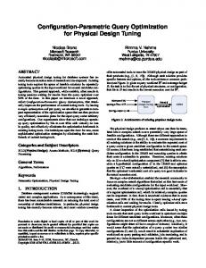
PREVIOUS RESULTS The goal of the research work performed during the Master tenure was to develop a parametric urban design system that would use information from the local context to drive the proliferation on the project site in Moscow, Russia. A series of computational tools using Rhinoscript was developed during the research. These tools use distance to the influencing elements as a driver to achieve differentiation and to articulate building geometry on a project site. The base setup includes a grid of points and an influencing element. The influencing elements become the immediate context of the site such as transportation nodes, park, roads and river. The base setup includes a grid of points and an influencing element (Figure 1, a). The variety offered by the computational tools includes shifting the position of points on the grid, creating connections with its neighboring points, scaling of elements and rotation all in
69
Figure 1. a. Initial point grid setup b. Point shift c. Orientation d. Connectivity e. Voronoi subdivision f. Geometry in Voronoi cell
absence of a convincing method for street network generation. The computational tool, which generates connections between points does not reflect any real-world information except for the proximity to certain influencing elements. It is neither possible to control the line length that connects the points nor the angle between lines. At some spots overlaps occur and the pattern has to be altered manually. Moreover, in our project a point defines the location of a building, which means that the connectivity lines bump into the building. Thereby we used the connectivity method as an analysis tool to illustrate the accessibility on the site. However, this method cannot be used to produce an actual road network. The same applies to Voronoi cell boundaries, which in fact represent the boundaries of the building geometry, hence can serve as a street network. Nevertheless, the resulting pattern is far from being realistic and can hardly be used for real world design tasks.
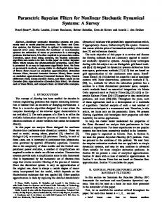
proportion with the distance value of each point from the influencing element (Figure 1, a,b,c,d). Voronoi is used as a method for space subdivision (Figure 1: e). Each Voronoi cell obtains additional geometric information, which defines a form of a future building (Figure 1, f). These tools are applied to the project site in Moscow, Russia. The application of the computational tools resulted in the urban design proposal illustrated in Figure 2.
Taking further the idea of using local context as a driver for proliferation on the project site we organized a teaching exercise. During this exercise the students were asked to develop an urban design proposal using parametric tools for a university campus in India. They had to investigate local topography, climate conditions, existing infrastructure and so on and to extract parameters that would control the urban design. Due to time limitations it was not possible for the students to develop the final urban design proposal. Therefore, they were combined in small groups, each group concentrating on a specific topic. The generation of a street network was one of the major tasks as it was a starting point for the design project. It was also a point of interest to
Figure 2. Final urban design proposal
The results of the Master research project proves the ability of computational tools to generate a great variety of building forms differentiated in response to the local context. However, the computational design method developed during the Master tenure has to be improved in order to be applied in real-world urban design practice. One of the main weaknesses of the proposed method is the
70
investigate further in the Master’s research work. We developed our own Grasshopper component library for street network generation and block subdivision based on (Vanegas et al. 2009) and (Weber et al. 2009) which was used by the students during their work on the design project. In the next sections we will discuss the details of each of the custom components and will share some results of the student research. 4.
COMPONENT LIBRARY C# in Visual Studio 2008 in conjunction with the RhinoCommon SDK and Grasshopper base libraries were used to develop the presented component library. It consists of four components: three street network generation components and one block subdivision component. Each component provides a set of additional input parameters, which are described in section 4.1. and 4.2.
Figure 3. Three street network components
By default, all input parameters are set to meaningful initial values. This results in a simple street network. Since Grasshopper allows users to get real-time feedback on parameter changes, one quickly gets an understanding of how variations influence the outcome. While the above parameters are available in all three street network components, two of them include additional inputs:
4.1. Street Network The strategy used for the street network generation is largely inspired by (Weber et al., 2009) and adapted to the capabilities of the RhinoCommon SDK. The RhinoCommon SDK provides support for NURBS. Therefore it was possible to extend the functionalities of the algorithms to among the three street network components (Figure 3): minLength: The minimal length of a street segment
maxLength: The maximal length of a street segment
deviation: The mean deviation angle applied to the desired direction of the street
minDist: If two junctions are within this distance, they snap together. This avoids very close, undesired junctions
growthSteps: A number of growth steps
A curve representing the boundary of the project site.
A set of curves representing existing roads to be integrated in the street network
All three components provide the same output parameters:
support the latter. Following input parameters are shared
The generated street segments as a set of line-like curves.
A set of closed curves representing urban blocks.
The corner points of the street blocks grouped correspondingly to the block they belong to.
Street segments can be used to build street profiles. Block boundaries can be used for a further subdivision with the corresponding component to derive a building geometry. Corner points of the third output can be used to articulate the open space and build geometry at a more local scale. On a logical level the street network is represented as a set of street segments (edges) and junctions (nodes). In
seed: Allows for setting of different seed values in order to create different solutions based on the same input
terms of Graph Theory, a graph can be described as G = (E;N), where E is a set of edges and N a set of nodes. While a publically available graph library (Quickgraph) was
startPoints: A set of points from which the street network starts to grow
tested, the implementation uses a custom graph library to stay lightweight in terms of memory and dependencies.
71
4.2. Block Subdivision The block subdivision component provides a way to subdivide closed curves from the street network into subregions.
Figure 4. Block subdivision component
The implementation is based on the algorithm described in (Vanegas et al., 2009) for block subdivision. According to (Vanegas et al., 2009) the algorithm represents blocks as polylines. The algorithm is adapted to support the NURBS curves. It proceeds by taking a closed base curve, usually the one representing a block. The block is then subdivided into two curves, which together form the shape of the base curve. The same procedure is recursively applied to the resulting sub-curves in order to create a further subdivision. We use the proposition of (Aliaga et al., 2009) to use oriented bounding rectangles as guide shape for the process. The minimal bounding rectangle is calculated. Further, the bounding rectangle is divided at the mid section of the longer side. The section line is used for dividing the corresponding curve into two sub-curves. In order to find the minimal oriented bounding rectangles of a polyline, an adaption of the rotating calipers algorithm was applied (Toussaint, 1983). While the rotating calipers algorithm uses polyline edges to calculate the bounding rectangles for each iteration, different angle offsets from the base orientation were used to calculate a number of oriented bounding rectangles. The one with the smallest area forms the minimal bounding rectangle. The algorithm is illustrated in Figure 5.
Figure 5. Subdivide curve
In the next section we present the work of our students and a case study, which illustrate possible implications of the component library in the design process. 5.
5.1. Student work Two students, Matthias Knuser and Tobias Wullschleger, used the component library in conjunction with other component libraries in Grasshopper to develop an urban design proposal for the university campus. Based on a terrain height and slope analysis they, yet manually, define primary roads. The location of major functions, such as the convention center, faculty buildings, housing as well as sport centers, is defined following the analysis part. Accompanying functions distribute independently around the major functions, e.g. faculty lounges near faculty offices; cafeterias near student rooms, lecture halls, offices, conference areas, etc. In order to distribute these functions, the whole organization diagram was translated into a springmass-system (Kangaroo) where the spring length represents desired distances between the core functions. A secondary street network is generated with the street network component taking into consideration slope analysis and functional distribution. The A* path-finding algorithm is used for finding the shortest paths interconnecting the major functions. Path lengths are used to evaluate the fitness of a road network. Evolutionary algorithms (Galapagos) are used to optimize the solution (Figure 6).
Two inputs are required to define a subdivision process:
A closed curve
A natural number representing the number of division steps
RESULTS
The process results in 2n curves, n>0 being the number of division steps.
72
Figure 8. Generated street network
Existing roads are seamlessly weaved into the network and the latter stays within the site boundaries whereas park and water body are excluded. The CurvesSplitIntersect component of the StructDrawRhino plug-in helps to split the roads at the park and water body boundary respectively. Road segments within these areas are removed with appropriate Grasshopper components. The boundaries are integrated into the network and serve as block borders (Figure 9).
Figure 6. Shortest paths between major functions
5.2. A case study The following case study illustrates the application of the developed component library for urban design. We demonstrate how to address local factors such as site boundaries, natural constraints (parks, lakes, forests) and existing infrastructure. Dimensions and parameters used in this case study do not reflect any real world parameters. They merely serve as a proof of concept to show how a parametric urban layout can be set up. Figure 7 illustrates a possible initial setup with existing roads in black, forest / park area in green and a body of water in blue. The red closed curve serves as site boundary. The generated streets remain within this boundary. Two points serve as distinct starting points for the network generation. Different street lengths and deviation values are assigned to each of the points.
Figure 9. Altered street network
In the next step we define three different areas (Figure 10), which can represent areas with different land values. On an abstract level they represent three different regions, which in this case are used for informing the lot area sizes.
Figure 7. Initial setup
This results in two distinct network topologies. These topologies automatically merge during the generation process. Moreover, existing roads and site boundaries are taken into account when the street network is generated. The site boundaries are altered by calculating the region difference between site boundaries and the forest on the right. This prevents the generation of streets in the forest. Figure 8 shows the generated network.
Figure 10. Areas with different land values (in pink)
Surface areas of the existing street blocks are therefore measured. Then, considering area type, the number of subdivision steps is estimated to achieve a lot area close to already defined goal area. The block subdivision component
73
then splits the block area into lots. A mixed usage is attained in the overlapping areas (Figure 11).
Figure 13. Rhino geometry
Figure 11. Block subdivision according to the area
6.
CONCLUSION AND FUTURE WORK We presented a method for parametric street network generation and block subdivision in Grasshopper. The possibilities of street network generation and block subdivision allows the user to combine procedural street generation and parametric design abilities of Grasshopper.
A parameter representing the gross floor area is then assigned to each of the areas. From that point, the floor area for each lot is calculated. This informs the building height (Figure 12). Building colors reflect the building intensity described in (Berghauser and Haupt, 2010). The presented parametric urban system reacts to changes of initial conditions such as site boundaries, position, size and number of water bodies or parks, shape and number of existing roads. While the system responds to these changes, it seeks to maintain desired gross floor areas for the different functional regions. The parametric nature of the model allows testing different scenarios within a short period of time. While Grasshopper is intrinsically parametric, the component library for the street network generation and block subdivision add the missing link to create urban layouts in Grasshopper. Figure 13 illustrates the combination of Rhino modeling features together with a generated street layout.
Performance of the street network component must be further optimized. One reason for unsatisfying performance on a technical level is the representation of the street network as a directed graph as well as an undirected graph. The latter is used for determining the cycles representing street blocks. Double implementation leads to performance bottlenecks and large memory use when applied at bigger urban scale. We managed to utilize the component for urban designs at the scale of a university campus (approx 80 hectares), but its application at the larger scale is not yet possible in Grasshopper. Another point for improvement is the cycle finding process. For certain street network configurations we fail to find all the cycles, which form street blocks. As a result, it is difficult to include an entirely parametric model on the block level, which would react to changes of the street network. A method to find all the required cycles in a consistent manner has to be introduced. By combining both the components for street network and block subdivision as well as other Grasshopper components, we were able to create hierarchical patterns. The incorporation of a standard graph library would allow the application of graph algorithms such as Dijkstra, Prim and Kruskal (Dijkstra, 1959; Prim, 1957; Kruskal, 1956). This would open up a new range of possibilities such as calculation of shortest paths and distances between points along the street network. In section 5 we presented an attempt to calculate the shortest path using the A* pathfinding algorithm. Important urban indicators such as
Figure 12. Building volumes
74
network density and other indicators described in (Berghauser and Haupt, 2010) could be directly calculated.. Direct evaluation and comparison of different solutions would be possible.
Traveling Salesman Problem. Proceedings of the American Mathematical Society, Vol 7, pp. 48–50
The subdivision component generally works well. Up to ten subdivision steps leading to 1024 subcurves still maintain the interactivity within the performance boundaries imposed by Rhino and Grasshopper. The recursive nature of the algorithm generates subcurves of order 2n. Alternative methods must be developed to achieve a variety in both subcurve geometry and their number.
MCNEEL, R. 2010. GRASSHOPPER - GLTERNATIVE MODELING WITH RHINO, McNeel North America, Seattle, USA. http://www.grasshopper3d.com/, Internet Accessed: 09.11.2010
MAYA AUTODESK, Official Website: http://www.autodesk.de/adsk/servlet/pc/index?siteID=403786&id=146575 12; Internet Accessed: 01.11.2010
MCNEEL, R. 2010. RHINOCEROS – NURBSA MODELING FOR WINDOWS (VERSION 4.0), McNeel North America, Seattle, W A, USA. www.rhino3 d.com/, Internet Accessed: 11.11.2010 MICROSOFT .NET FRAMEWORK, Official Website: http://www.microsoft.com/net/, Internet Accessed: 19.11.10
In our future work we will concentrate on the development of evaluation and optimization methods for the street network generated by the components. All components currently work on a plane. It would be useful to incorporate terrain information, e.g. to create more meaningful networks by taking into consideration the slope/landscape variations. The introduction of local context information as illustrated in the case study or the shortest path algorithms applied by students are examples of optimization strategies.
MICROSOFT VISUAL STUDIO, Official Website: http://msdn.microsoft.com/vstudio/, Internet Accessed: 19.11.10 STANDARD ECMA-334 - C# LANGUAGE SPECIFICATION (ECMA International,2006), http://www.ecmainternational.org/publications/files/ECMA-ST/Ecma-334.pdf, Internet Accessed: 19.11.10 TOUSSAINT G., 1983. Solving geometric problems with the rotating calipers, Proc. MELECON '83 PRIM R. C., 1957, Shortest connection networks and some generalizations, Bell System Technical Journal, pp. 1389–1401 QUICKGRAPH, GRAPH DATA STRUCTURES AND ALGORITHMS FOR .NET, Version 3.3, 2010, Official Website: http://quickgraph.codeplex.com/, Internet Accessed: 19.11.10
References ALIAGA D. G., VANEGAS C. A., BENES B., 2008. Interactive example-based urban layout synthesis. ACM Transactions on Graphics 27, 5, 1–10 BERGHAUSER PONT M., HAUPT P., 2010. Spacematrix: Space, Density and Urban Form, NAi Publishers, Rotterdam
RHINO .NET FRAMEWORK SDK, Official Website: http://wiki.mcneel.com/developer/dotnetplugins, Internet Accessed: 19.11.10
CITYENGINE (PROCEDURAL INC. 2010). Official http://www.procedural.com/, Internet Accessed: 09.11.10
RHINOCOMMON SDK, Official Website: http://www.rhino3d.com/5/rhinocommon/, Internet Accessed: 19.11.10
Website:
DERIX C., 2009. In-Between Architecture Computing, International Journal of Architectural Computing, Issue 04, Volume 07, pp 565-585
STEINO N, 2010, PARAMETRIC THINKING IN URBAN DESIGN, Paper for the ASCAAD Conference
DIJKSTRA E. W., 1959. A note on two problems in connection with graphs, Numerische Mathematik 1: 269–271 GECO ([UTO]), Official Website: http://utos.blogspot.com/, Internet Accessed: 19.11.10
VANEGAS C. A., ALIAGA D. G., BENEŠ B., WADDELL P., 2009. Visualization of Simulated Urban Spaces: Inferring Parametrized Generation of Streets, Parcels, and Aerial Imagery, IEEE Transactions on Visualization and Computer Graphics, 15(3), pp. 424‐ 435
GEOMETRY GYM (GEOMETRY GYM LTD.), Official Website: http://ssi.wikidot.com/ Internet Accessed: 14.1.11
VORONOI DIAGRAM, Wikipedia: http://de.wikipedia.org/wiki/VoronoiDiagramm, Internet Accessed: 10.11.2010 WEBER B., MUELLER P., WONKA P., GROSS M., 2009. Interactive Geometric Simulation of 4D Cities, EUROGRAPHICS, Volume 28, N 2
HART, P. E.; NILSSON, N. J.; RAPHAEL, B., 1968. A Formal Basis for the Heuristic Determination of Minimum Cost Paths. IEEE Transactions on Systems Science and Cybernetics, SSC4, 4 (2): 100–107 KANGAROO (PIKER D.), Official Website: http://spacesymmetrystructure.wordpress.com/, Internet Accessed: 14.1.11
KRUSKAL J. B., 1956. On the Shortest Spanning Subtree of a Graph and the
75