Trk = P fs f n-r'ur(iwe + W.V)tp~-dS. (5). ⢠p port-starboard anti-symmetric mode shape. The outward- if ur is a directed normal vector on the wetted surface [] = {nl, ...
Marine Structures 6 (1993) 143-163
Composite Singularity Distribution Method with Application to Hydroelasticity Yousheng Wu, Dayun Wang China Ship Scientific Research Center, Wuxi, China
& H. Ronald Riggs & R. Cengiz Ertekin University of Hawaii at Manoa, Honolulu, HI 96822, USA
ABSTRACT In predicting the wave-induced motions of a ship or an offshore structure, the symmetry of the body is widely used to reduce the computational time. By employing the symmetry condition, the composite singularity distribution method (CSD) can provide a consistent and efficient way to solve the diffraction and radiation problems. With this method, a single plane of symmetry is exploited such that the exciting forces due to incident waves of arbitrary heading can be calculated without distributing sources on the entire body. This paper presents the double composite singularity distribution method (DCSD) for the hydroelastic analysis of a structure which has two planes of symmetry. Applications are illustrated with reference to a very large, multi-hull floating structure. Key words." hydroelasticity, very large floating structure, finite-element method, mode superposition analysis, dynamic response.
1 INTRODUCTION Singularity distribution methods have been successfully employed to predict the motions and loads of large marine structures in waves. Most marine structures have port-starboard symmetric profiles. This has been extensively used to reduce the computational effort in seakeeping 143 Marine Structures 0951-8339/93/$06.00 © 1993 Elsevier Science Publishers Ltd, England. Printed in Great Britain.
144
Yousheng Wu, Dayun Wang, H. Ronald Riggs, R. Cengiz Ertekin
analysis. One c o m m o n method is to use the information of each oscillation mode of the body to determine the symmetry relationships of the singularity strengths and the velocity potentials for the corresponding radiation wave over different parts of the body wetted surface, and hence, to represent the boundary-integral equation for solving the singularity strengths on a much smaller area of the surface. However, when the incident wave is not symmetric with respect to the principal axes of the body, this simple method still requires that the diffraction problem be solved over the entire wetted surface. Furthermore, when the distortions of a flexible structure are to be included, exploiting the symmetry conditions is not as straightforward as in the case of predicting the rigid body motions. To overcome these difficulties, Price & Wu j.: suggested the use of the composite singularity distribution (CSD) method. The CSD method provides a rigorous mathematical formulation for using the port and starboard symmetry properties to evaluate not only the radiation problems, but also the diffraction problems for a rigid body travelling in waves with arbitrary heading angle. This method was subsequently extended in Refs. 3 and 4 to account for the response of flexible structures, and hence to establish an efficient computational approach for three-dimensional hydroelastic analysis. In this paper, following a brief description of the CSD method, the same concept is applied to a structure with two planes of symmetry, and the double composite singularity distribution (DCSD) method is presented. The DCSD method permits the hydrodynamic actions of radiation, diffraction and incident waves around a very large flexible structure with both port-starboard, and fore-aft symmetries to be determined by performing all the computations over only a quarter of the body wetted surface, independent of the incident-wave angle. The DCSD method is shown to be efficient for the semi-submersible type of very large floating structures. The CSD method has been successfully applied to mono-hull and multi-hull vessels (SWATH ships, semi-submersibles), dry docks, jack-up rigs, etc. (Refs. 5, 6 and 7). To illustrate the application of the DCSD method, responses are calculated for a 5-module, very large floating structure. One of the analysis methods used recently in Refs 8, 9 and 10 is based on an application of a variation of the DCSD method to very large floating structures (VLFS). 2 EQUATIONS OF MOTION Consider a flexible, floating structure travelling with constant forward speed U at an arbitrary heading angle Z in regular, sinusoidal incoming
Composite singularity distribution method and hydroelct~ticity
145
waves of amplitude A~, frequency o9, and wave number k (or wavelength A). The motions of the structure and the fluid are described in this paper in an equilibrium coordinate system Oxyz, which moves with the forward speed U in the Ox direction. The Oz axis points upwards and the Oxy plane lies on the undisturbed water surface. A flexible dry structure has a series oforthogonal principal modes and several rigid-body modes. If the structure is discretized with m degreesof-freedom, then the displacement vector u at any arbitrary point within the structure may be expressed as an aggregate of distortions in the principal modes, namely
u(x,y,z,t)
= { u , v , w } "r =
{ur, v~,w~lVp~(t) (1)
ur(x,y,z)pr(t) = r=l
r=l
where ur denotes the vector of the rth principal mode shape vector associated with the dry structure, Pr represents the corresponding principal coordinate, and T indicates transpose. Assuming that the fluid is incompressible and inviscid, and the flow is irrotational, the fluid motion and the hydrodynamic actions around a flexible structure may be determined by employing the three-dimensional potential theory as discussed by Price & Wu 5 and Bishop et al. 4 The generalized linear equations of motion of the floating structure in waves may then be expressed in the form (a+A)ii+(b+B)l~+(c+C)p
=
F e ~°~o'
(2)
where o9e is the frequency of wave encounter, a and c are the symmetric principal mass and stiffness matrices of the dry structure, b is the generalized structural damping matrix (which is usually assumed diagonal), and A, B and C are the hydrodynamic inertia, damping and restoring matrices, respectively. Also, p and F are the m X 1 column vectors representing the principal coordinates and the generalized wave exciting forces, respectively.
3 COMPOSITE SINGULARITY DISTRIBUTION METHOD (CSD) If a flexible structure has port-starboard symmetry, i.e., the geometric shape of its wetted surface and the distributions of its mass and stiffness are symmetric with respect to the central plane, Oxz, the CSD method given by Wu 3 and Bishop et al. 4 can be employed to allow all the
146
Yousheng Wu, Dayun Wang, H. RonaM Riggs, R. Cengiz Ertekin
h y d r o d y n a m i c matrices a n d vectors in eqn (2) to be calculated over half of the wetted surface, for example, the port part, S v. The elements of A a n d B are of the form
Ark
=
1
Brk
1 :;-(Trk)
-
O)c
for r = 1, 2 . . . . .
m,
(3)
O~c
a n d k = 1, 2 . . . . . m. In these expressions,
Trk =p £ re" -
Ur(iWe + W" V)*Z- d S
(4)
p
if ur is a p o r t - s t a r b o a r d symmetric m o d e shape, a n d
Trk = P fs f n-r'ur(iwe + W.V)tp~-dS •
if ur is a port-starboard anti-symmetric m o d e directed n o r m a l vector on the wetted surface [] = the velocity of the steady flow relative to the coordinate system. A pair of composite functions radiation potential a m p l i t u d e are defined as
l£,f
O # ( x , y , z ) = 4-~
P
(5)
p
o#a±dS
u£
+ 4rig
shape. The outward{nl, n2, t/3} T. a n d W is m o v i n g equilibrium 0~ a n d 0~- of the kth
O~Gen{dC
(6)
P
where Cp is the water-line of the port-part of the structure surface, a n d
G+(x,y,z, x l , y l , z l )
= G(x.y,z, xl,yl,zl) + G(x,y,z, xl,--yl,zj)
G-(x,y,z, xj,yl,zl)
= G ( x , y , z , xt,y~,zl) - G ( x , y , z , xl, - Y l , Z l )
(7)
The appropriate Green function G satisfies Laplace's equation, the linearized free-surface b o u n d a r y condition, c o r r e s p o n d i n g to the steady velocity - U , the sea-bed condition, a n d the radiation condition. According to Ref. 4, the composite source strengths Q[ a n d Q[ (k = 1, 2 . . . . . m) can be solved from the body-surface b o u n d a r y condition
On
- Pv
f o r k = 1,2 . . . . . m, o n S v
The right-hand side of this equation can be expressed as
(8)
Composite singularity distribution method and hydroelasticity
P~ = 2 i09~Uk+
(VXuk) XW-(uk.V)W
147
.n
P~- = 0
(9)
"n
P~- = 0 (10)
for symmetric modes of uk, and P~- = 2 io)euk+
(V×uk)
XW--(uk.V)W
for anti-symmetric modes of uk. The elements of F are the generalized wave exciting forces which can be written, for r = 1, 2. . . . . m, as
F~ = Pfs f nT'ur(i°~e + W'V)ItP°+- + q~g]dS
(II)
p
where the superscript + is used when u, is port-starboard symmetric (anti-symmetric). The composite functions 00+ and 4~o are defined by
:p~(x,y,z) = (po(x,y,z) + ePo(X, - y , z )
(12)
with 0o being the amplitude of the incident wave potential. The composite diffraction wave potentials 4~g and ~ may be obtained from the same set of equations (6)-(8), except that the subscript k in this case should be replaced by the subscript D, and
PD(X, y,z) =
~Onn
¢,.y.:)
Offn
I.,-.-y.=)
The elements of the restoring matrix C are given by
Crk = --2pg fs f nT.urwkdS
(14)
p
when both the rth and kth mode shapes are symmetric or antisymmetric, and
c,k
=
0
(15)
when one of the rth and kth mode shapes is symmetric while the other is anti-symmetric.
4 DOUBLE COMPOSITE SINGULARITY DISTRIBUTION METHOD (DCSD) When a body has two planes of symmetry, that is to say, the geometry of its wetted surface and the configuration of its structure are portstarboard symmetric with respect to the Oxz plane and fore-aft
148
Yousheng Wu. Davun Wang. H. Ronald Rig, s. R. Cengiz Ertekin
symmetric with respect to the Oyz plane, the double composite singularity distribution method may be introduced to solve both the fluid and structural dynamic problems in one quadrant of the fluid and structure domain. Hereafter, it is assumed that the perturbation of the steady flow due to the presence of the body is negligible, namely W = - ( U . 0,0)
(16)
In a corresponding approximation, the linear radiation problem of a flexible structure may be calculated by applying the pulsating source Green function in infinite or finite water depth, and in the presence of the free surface. Based on the properties of the symmetry and reciprocity of the Green functions (Ref. 3), and the symmetry of the geometry and principal mode shapes of the structure, the following formulations may be obtained. 4.1 Double composite velocity potential By denoting
q+(x,y,z) = q(x,y,z) + q ( x , - y , z )
(17a)
¢p~.(x,y,z) = (9+(x,y,z) + ~ + ( - x , y , z )
(17b)
q+(x,y,z) = q + ( x , y , z ) - q + ( - x , y , z )
(17c)
G+(x,y,z, xt,yl,zl) = G+(x,y,z, xl,yl,zl) + G+(x,y,z,--xl,yt,zl) (17d)
G~(x.y,z, xl,yl,zl) = G+(x,y,z, xl,yl,zl) - G+(x,y,z, - x t , y l , z l ) (17e) the double composite velocity potential can be represented by 1
q+-4zt q+ _
1
4rr
U2
fs J Q+-G+dS ~ g ,,,
Q+G+dS + -
-
4~
Jc,,,.Q+G++n~dC
(18a)
n~dC
(18b)
,,,
where the integrations are only taken over the wetted surface and the water line of the port and fore quadrants of the structure (x > 0, y >~0), denoted by Spt,and Cpt., respectively. A similar set of equations for q 7., O_S, G+ and G- may be introduced by replacing the superscript + by the superscript - in eqns (17) and (18). In the above equations, the symbols q and Q denote the amplitude
149
Composite singularity distribution method and hydroelasticity
o f the potential a n d the source strength respectively, a n d can either refer to each o f the r a d i a t i o n potentials ~, (r = 1, 2 . . . . . m) a n d the c o r r e s p o n d i n g source strengths Q,, or the diffraction potential 0D a n d its source strength QD. A p p e a r i n g together with the superscript a n d the subscript + or - , they represent the c o r r e s p o n d i n g d o u b l e c o m p o s i t e functions.
4.2 Interface boundary conditions T h e b o d y surface b o u n d a r y c o n d i t i o n s used to solve the d o u b l e c o m p o s i t e source strengths Qr+, ÷ Q ,÷- , QT+ a n d QT- c a n n o w be written in the form s h o w n in T a b l e 1, w h e r e Prt = 4i09enT'u,
(19a)
and P,2 = 2 U
n3 k Oz
Ox
]
- n:
\ Ox
(19b)
ay ] J
T h e b o d y surface b o u n d a r y c o n d i t i o n s for 0~+, 0 ~-, 0 fi+ a n d 0 B - are 005+
On
_ P~(x, y,z) + PS(-x, y,z),
O0 ~_ _ p ~ (x, y, z) - P~ ( - x , y, z)
(20a)
On
TABLE 1 Boundary Conditions for the Double Composite Radiation Potentials (on U r Fore-aft symmetric mode
ao,+÷ Ur
Port-starboard symmetric mode
n r
Port-starboard anti-symmetric mode
On
a,, +_ = Prl;
On = P''-
Spf)
ur Fore-aft anti-symmetric mode
ao,++
ao,+_
On = P,2:
On = P,t
a07+ = dO;-- = 0 an an
dO;-+ = dO;-_ = o an an
a o T + _ a o , +_ = o
a°~+÷ = a°~+- = o
an
ao;-+ = p,~: On
an
a07_ = p,~ an -
an
a07+ _ _ = p,,: an -
On
a0;_ . = p,~ an
Yousheng Wu, Dayun Wang,14. Ronald Riggs, R. Cengiz Ertekin
150 and
Ocp~+ On - P~(x,y,z) + P~(-x,y,z), Odp~_ _ P~(x,y, z) - P~(-x, y, z) On
(20b)
The expressions for P~ and P~ are given in eqn. (13).
4.3 Hydrodynamic coefficients The elements of the hydrodynamic inertia and damping matrices are defined by eqns (3). The complex functions Trk for r = 1, 2 . . . . . m and k = 1, 2 . . . . . rn are as follows. (i) w h e n Ur is both a port-starboard and a fore-aft symmetric mode:
Trk = p f s , j n+.ur(iwe- UO)4~[+dS
(21a)
(ii) W h e n Ur is a port-starboard symmetric and fore-aft antisymmetric mode:
T~k = pfsp, f n T ' u r ( i o o e - U ~ ) ( P ~ _ d S (iii) W h e n u~ is a port-starboard symmetric mode:
Trk
(21b)
anti-symmetric and fore-aft
= p fsp,f nV'ur(iwe- UO)c-;+dS
(21c)
(iv) W h e n ur is both a port-starboard and a fore-aft anti-symmetric mode:
Tr,,, = p fs~,f nr.u,.(ioge-U~),~;_dS
(216)
4.4 The restoring coefficients W h e n one of the rth and kth mode shapes is port-starboard symmetric, while the other is anti-symmetric; or one of the rth and kth mode shapes is fore-aft symmetric, but the other is anti-symmetric, Crk = 0
(22a)
Composite singularity distribution method and hydroelasticity
151
In all other cases,
fnT'urwkdS
C,k = -4pg fs
(22b)
pf
4.5 The generalized wave exciting forces
The generalized wave exciting force components, Fr (r = 1, 2 , . . . , m), have a form similar to eqns (21). If the mode ur is (i) port-starboard and fore-aft symmetric:
F~ = P fspff nT'ur(iCoe-- U ~x)(Oo O \ +++ O~+)dS
(23a)
(ii) port-starboard symmetric and fore-aft anti-symmetric:
F,. = p fs ,ff nV.u,.(iwe-UO)(O+o_ + e f _)dS
(23b)
(iii) port-starboard anti-symmetric and fore-aft symmetric:
Fr = ,Ofs f n'r.u,.(iO e- U-fx)(Oo+ +
(23c)
pf
(iv) both port-starboard and fore-aft anti-symmetric:
F~ = p :s f nV'ur(ioJe-- UO)(rpo_ + gJD_)6S
(236)
pf
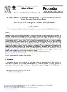
5 HYDROELASTIC ANALYSIS OF A FIVE MODULE VLFS The DCSD method is especially suitable to analyze the hydroelastic response of multi-module large floating structures, such as the one shown in Fig. 1. This structure consists of five identical semi-submersible modules, each with deck dimensions of 100 m × 100 m, four columns and two pontoons. Some of the particulars are listed in Table 2. The details of the conceptual design of the modules used here can be found in Winkler et al., l~ and several of its applications were discussed in Ertekin et al) 2 The adjacent elastic modules are joined by flexible connectors at both the deck and pontoon levels. Riggs et al) 3 and Wang et al) 4 have used the same 5-module VLFS to analyze its response by employing strip theory and the rigid module, flexible connector (RMFC) model, respectively. A comparative study of different methods can be found in Ref. 9 and the irregular-sea responses were given in Ref. 15.
152
Yousheng Wu, Dayun Wang, H. Ronald Riggs, R. Cengiz Ertekin Connectors at the deck level
z
Y
,,, • ~
,n
. . . .
J
LI :
-
"-]
g_"
"
"_ILl.'---"
"J
- . t
--------~. ,.--,,,.---~ _ .,_,._...J.._.._--.- l
"-=IP'-"~
"
" L C o n n e c t o r s at the pontoon level
Fig. 1. S c h e m a t i c d i a g r a m o f a 5 - m o d u l e VLFS.
TABLE 2 Properties of a Module and Connector
Dimensions Module
Pontoon
Column
Length Width Height
100 m 100 m 59 m
96 m 18 m 10 m
12 m 17 m 35 m
KG KB GM L
30.67 m 8.25 m 5.01 m
Operating properties GMT Operating draft displacement
4.13 m 25 m 46 440 X 103 kg
Stiffness coefficients of connectors T r a n s l a t i o n a l in x, y, a n d z d i r e c t i o n s Rotational
2.5 × 10⁹ N / m 1.0 × 10 I° N m / r a d
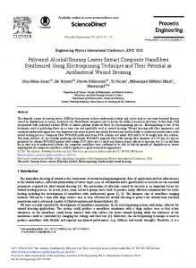
The finite-element m e t h o d was e m p l o y e d to determine the principal modes of the dry structure up to a n d including r = 16. Figure 2 shows selected symmetric (vertical bending) a n d anti-symmetric (horizontal b e n d i n g a n d twisting) principal dry modes. Except for the six rigid-body modes (r = 1 for surge; r = 2, sway; r = 3, heave; r = 4, roll; r = 5, pitch; a n d r = 6, yaw), the m o d a l characteristics for the first ten flexible-body modes are presented in Table 3. F o r the hydroelastic analysis, the entire wetted surface of the five m o d u l e s at their m e a n position is discretized into 2560 facets. However, only a quarter of the n u m b e r of facets (640) are used in the analysis by e m p l o y i n g the D C S D method. In the current analysis, the VLFS has no forward speed (U = 0). The h y d r o d y n a m i c coefficients (added mass A,~ a n d d a m p i n g B~,) for r = 2, 3, 4, 5 (rigid b o d y modes), r = 7, 10, 13 a n d 15 (vertical b e n d i n g with two,
Composite singularity distribution method and hydroetastieity
r - 7
r = 8
r
r = Ii
153
z
r
=
12
r = 15 ~
Fig, 2. Dry modal characteristics of the 5-modute VLFS.
TABLE 3
Calculated Natural Frequencies, Generalized Masses and Stiffnesses of the Dry VLFS Mode number r
7 8 9 10 11 12
13 14 15 16
Mode shape Portstarboard
Fore-aft
Symmetric Anti-symmetric Anti-symmetric Symmetric Anti-symmetric Anti-symmetric Symmetric Symmetric Symmetric Anti-symmetric
Symmetric Anti-symmetric Symmetric Anti-symmetric Symmetric Anti-symmetric Symmetric Symmetric Anti-symmetric Symmetric
Natural Generalized Generalized frequency mass stiffness o~, (rad/s) (kg m: × lOs) (kg meZ~: × 109)
2.06905 2.83359 3.05834 4.52942 5.88804 6.08608 6.87757 7.27593 8.76504 9.05281
0.72448 1.24424 0-71937 0.85740 1.19223 0.83757 1-96054 1.94952 2.12678 1.07692
0.31015 0.99903 0,67286 1.75901 4.13334 3-10239 9-27354 10.32059 16.39184 8,82572
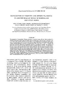
three a n d f o u r nodes, respectively), r = 8, 11 (twisting d o m i n a n t m o d e s with o n e a n d two nodes), a n d r = 9 a n d 12 ( h o r i z o n t a l - b e n d i n g d o m i n a n t m o d e s with two a n d three nodes) are illustrated in Figs 3 a n d 4. To o b t a i n d i m e n s i o n l e s s coefficients, L = 496 m (length o f the s u b m e r g e d
Yousheng Wu, Dayun Wang, H. Ronald Riggs, R. Cengiz Ertekin
154
10
2.0
8--
1.5
!
1.o
~
I'
4~
0.5
22
o.o o,o i ' l l l r ~ ; I l l l l l l ~ 0 . 4
0.I8 l i [ ~ [ 1 1 . I 2 1 J l ~ l 1 1 I.
IIII111~T11111111 0,8 1.2 1
0 .;4
(rod/s)
2oI
(rod/s) 2.5
1.5
/
0.5
0.0
1
I
m, 0.5 .
if'
iii,illlllilli,.]8,,rlilll2iii,,! ~ 0 0. 4
0.4
(rad/s)
.
' ~ T'I.J2'~ ~J'~.
(rod/s) 0.04
0.02
0.03
~002
"~ 0.01
< "~. o.oi 0.00
IITIII[
o.o
~.l,' ~
III[
~.18~
lllllrllllllli
~.2
1.
(rod/s) 0.2
~
o.00 o, )
0.2 ~F
___J I T T T T I I I 1 1 1 1 [ , 1 1 11 i i i i i I~T [ i l r l ] 0.4 0.8 1 .'2 1.6
(rod/s)
0.1
< .,t 0.0
o~o,,,,~,,IJ,,,,, • 0.4 O.18~Frr"l12'J' " ~I 6 (rod/s)
Fig. 3. Dimensionless generalized hydrodynamic coefficients (rigid modes).
body), V = 2.265 × 10⁵ m 3 ( s u b m e r g e d v o l u m e o f the five modules), a n d al = 1 m (wave amplitude) are used. N u m e r i c a l tests were c o n d u c t e d to confirm that the results given by the D C S D m e t h o d are in full agreement with those o b t a i n e d by the C S D method. In these figures, the h y d r o d y n a m i c coefficients are scattered in
Composite singularity distribution method and hydroelasticity 0.7
0.'8
::::: ~¢:::: ~=::::
0.3 -
0,
, .
.
,~l. ....... ; T8...... ~12...... I
0.0
r=tO r=t3
I ,~
ITTT
~
iiii
IIIITF#
.2
(rQd/s)
I
2
r= 7
0.2
~
1.0
155
I
(rod/s) ::::=
r:
::::~
r=ll
1.5
8
• -~ _~ -4
::::: ::::o
r= 8 r=l 1
~0.5
J 0,0
-~lillil
oo
~,14'
IITII
~.18'
IIIIil
2
IIII111
0.6
1
o.o o,o,~i%, ...... ;'8...... 1'2'"" '; I ¢~ (rod/s) 1.5 =:=== ::::o
===== r= 9 c:::: r=12
0.4
1,0 -
~
~ 0.2 0.0
r= 9 r=12
0,5
O I I I l ~ l ] l t l~l El IFl oI I I8~ 0 . 4 .
(rod/s)
.2 I l l l I I
q
-
.... ~ .0 0 ) I T T T T T I I I I I I I I o I s I I I I I ] I o . 4
,
.2111111
(rod/s)
Fig. 4. D i m e n s i o n l e s s generalized h y d r o d y n a m i c coefficients (flexible modes).
the middle frequency range 0.4 < o9 < 1.2 rad/s where different types of fluid interaction arise between the pontoons and columns. It was observed that w h e n the damping coefficients Brr attain peak values, the corresponding added mass coefficients Art change from a local m a x i m u m to a local m i n i m u m value. This has been c o m m o n l y observed for semi-submersibles, SWATH ships and other multi-hull vessels. In addition, as the number of nodes of the vertical bending modes increases, the corresponding added mass coefficients increase over the entire frequency range.
Yousheng Wu, Dayun Wang, H. Ronald Riggs, R. Cengiz Ertekin
156
Selected generalized wave exciting forces for the port and starboard symmetric modes (r -- 1, 3, 5, 7, 10 and 13) for the five-module VLFS in both head and quartering seas of unit amplitude are shown in Fig. 5. The amplitudes of the wave exciting forces display oscillatory behavior, and they are larger in head than in quartering seas. The principal coordinates corresponding to the port-starboard symmetric modes for head and quartering seas with unit wave amplitude are shown in Fig. 6 w h e n the structural damping is ignored, namely 4.0 -
I i
::::o
8
o
"~ ~ 0
•o.
~
.
o.~
.
-
q~orl. SeO 3.0
~
>o 2.0
-'; -
i
~C 1.0
. o.~
.
,.2.
.
1
.
0.0 .
(~o(~/~)
o.~
o .', . . . .
~
; ~. . . . . . . 1'2 . . . . . . . i .6
(rod/s)
,0~ q ~q 6
$, ,.z -
2
, III(~
0~0~ C~
.7.
2
L ~2 0
' ' l l l I 2. I ' l ' ' q ' 1
(~od/,)
(rod/'s)
OI
Ti •
0.8
¢~ (rod/s)
1.2
i
0
1.
¢0 (rod/s)
Fig. 5. D i m e n s i o n l e s s generalized wave-force amplitudes for head and quartering seas•
Composite singularity distribution method and hydroelasticity 2.0 _~
~
head sea quari', sea
157
0.010
1,5
-
c7
1.0
% 0.005
0.5
0.000 0,10'
0,4
0.8 (rod/s)
1.2
1.6
¢.
l~r~li 11:ll]r~rlr! I 0.8
c~
1.2
.6
.~ . ,. .
6
(rod/s)
0.003
0.02
- -
;TTT 0.0
0.01 0.001
0.00 O.FOI I I It I I [ I l T l t I F [ I~TTTTT[TTTT'rTi 0.4 0.8 1.2 1.6
0.000 0.0. . . .
(rod/s)
0.08
;]4 ....
018. . . . [
(rod/s)
0,001
I
0.06
- -
0,04 l
0.00
';llllttl~] 0.0' 0.4
Illilllilir.r2[T1111 0.8 1
(rod/~)
0.000 1.6
(rod/s)
Fig. 6. Principal coordinate amplitudes in head and quartering seas.
b = 0. These are in fact the transfer functions o f heave and pitch motions (r = 3 and r = 5) and the vertical distortions (r = 7, 10, 13 and 15) of the structure. For this five-module VLFS, the heave resonant frequency is o93 = 0.283 rad/s while the pitch resonant frequency is o95 = 0.287 rad/s. This explains w h y [P3I and IPsI attain peak values at almost the same frequency. The displacement u at any point within the structure may then be calculated by employing eqn (1). Figure 7 shows selected numerical
158
Yousheng Wu, Dayun Wang, H. Ronald Riggs, R. Cengiz Ertekin
"6 ":
o.j
(a)
(c)
Deck, Head Seas
Pontoon, Head Seas
Deck, Quar. Seas
(d)
Pontoon, Duor. Seae
i
(e)
Deck. Head Se0s
(f)
Deck, Ouar. Seae
Fig. 7. Vertical deflection amplitudes: (a)-(d) along the deck and the port pontoon center lines for the flexible 5-module VLFS obtained by the present method; (e)-(f) along the deck center line for the hinged 5-module (each module rigid) VLFS obtained by the method of Ref. 14.
results obtained by the present work for a VLFS with flexible module and flexible connector (FMFC) model, and those given by Ref. 14 for a hinged, rigid module flexible connector (RMFC) model. Figures 7(a)-(d) show the variation in the amplitudes of the vertical deflections of the deck along the center line y = 0 m, and of the port pontoon along its central axis y = 39.0 m, for both head and quartering seas of unit
Composite singularity distribution method and hydroelasticity
159
amplitude. In these figures, the origin of the x axis is located at the stern of the model. It is observed that the resonances of heave and pitch occur at nearly the same frequency a~--0.286 rad/s. The m a x i m u m deck displacements, which occur at the fore and aft ends of the VLFS, are equal to 1.46 m for head seas and 1.67 m for quartering seas. At the pontoon level, the m a x i m u m displacements are 1.45 m for head seas and 1.61 m for quartering seas. Figures 7(e) and (f) show the distribution of the vertical displacements along the center line of the deck of the R M F Model, where the m a x i m u m values are 2-41 m for head seas and 2.37 m for quartering seas. These values are greater than those for the F M F C model by a factor of a r o u n d 1.3-1-4. Evidently the R M F C model only distorts at the hinged joints; however, the F M F C model deflects smoothly due to the flexibility of both connectors and modules. In the design of a VLFS, one of the most important tasks is to determine the interaction forces between the connectors and the modules. This is the major loading imposed on the structure, which may result in local damage if it exceeds the design threshold value. Figures 8- l 1 show the calculated components of connector forces in thex,y and z directions for the connectors between modules 1 and 2, and between modules 2 and 3 at both the pontoon and deck levels in the case of head seas and quartering seas, respectively. It is apparent that in head seas, the connectors at pontoon level sustain greater forces in all three directions than the connectors at deck level. In quartering seas, the situation is different. In all cases, the connector forces in the x direction are dominant, especially between modules 1 and 2. The most severe case for the connectors at both the deck and pontoon levels is when the VLFS is excited by quartering seas of frequency 0.65 rad/s.
6 CONCLUSIONS Based on the symmetric properties of the flow and the dry principal modes of a structure, with both port-starboard and fore-aft symmetries, the double composite singularity distribution method (DCSD) is developed. It is used to calculate the potential flow around, and the hydroelastic behavior of a very large, flexible floating structure in waves. The D C S D method provides a unified mathematical formulation for the application of the symmetric properties of the fluid-structure interaction system in the calculation of both the hydrodynamic actions a n d the structural response to waves of arbitrary heading. By employing this method, all the numerical calculations are carried over a quarter of the body's wetted surface, and hence a major reduction in computational
Yousheng Wu. Dayun Wang, H. Ronald Riggs, R. Cengiz Ertekin
160 12000 "_~
c=cc: Module 1&2
80001
8000 ~
x-directlon
: III
• ooo ~
Module 1&2 ===== Module 2&3
¢::::
===== Module 2&3 x -direction
~
6000
=t ,ooo
,': '/l
/
200
~Oi 0......
(~14......
(rad/s)
w
2500
1
ii
3ooo. !
f'-I 0.0
,-*re,rio° /
! "i
2ooo. J
/
/I i/\/3
I!' 0.4
]lillTti] 1.2 ~.6
,-oo-1 /Ji
(rod/s)
Module 1&2 ===== Module 2&3 :::::
-~ 2000 i
ri
t 500
~ I
y-direction
o o io, ~ .... ;), . . . . . . ;'8
,,'2
~.16
(rod/s)
3000
0=:== Module 1&2 ~ : = : = Module 2&3
/'~
(~j8. . . . . . I[2T ......
I
: ,i I T I [ ~ I I 0.8 (rod/s)
4.000 ~-
I
,~
Z-direction
q
ooo! /
: : = = ~ Module 1&2 : : : = = Module 2&3
z-direction
2000 ~ tO00
o0.0 ~
'0.i4
6 ~.'
(rod/s)
Fig. 8. Amplitudes of forces acting on connectors at the pontoon level in head seas.
'''~.Fa~'T~'1~r~l.2
~l.le
(rod/s) Fig. 9. Amplitudes of forces acting on connectors at the deck level in head seas.
requirements is achieved. The application of this method to a fivemodule VLFS gives both the motions and distortions of the structure, and subsequently the stress distribution may be evaluated. This is left for future work.
Composite singularity distribution method and hydroelasticity --
15000 ~ ~ -
c:::: H~
15000
Module I&2] Module 2&51 x -direction
::::o :::::
161 Module I&2 Module 2&3 x-direction
10000
I
O• J
. . . . (~.|4. . . . .
{~.I8. . . . . .
1.12. . . . . .
OoIollFIIllJlill411
;•J
0.4
40 ~ l IL
Irrl i ,'
1.6
(rod/s)
.300
c : : : : Module 1&2 I . . . . . Module 2&3J y-dlrection [
l 2T o.~'"'~I •
ca
(rod/s)
::::~ :::::
g
Module 1&2 Module 2&3 y-direction
200
0
0.0
I
0.4
;IIIilIIIIITI 0.8 '.a ( r o d / s )
8000 _~
'~
.2
/lliiJ
0
~ .16
]iTliFnlll~l 0.0 0.4
2500
~ Module 1&2 ;===: Module 2&3 z-dlrection
IIIIIITITTT ITIrrTI 0.'8 .2 I. (rod/s)
,
:::::
::::: ~
2000~
l
Module 1&2 Module 2&3 z-directlon
4000
2000
0
Fig.
I0.
connectors
i
!~ ! , 0~,
Amplitudes at
08 (rod/s) of
the
forces
pontoon
12
I I
o o.b ......
;.I ......
;.I 8 ......
i.'~ ......
i.'~
(tad/s) acting
on
level
in
Fig. 11. Amplitudes of forces on connectors at the deck level in quartering
quartering seas.
seas.
ACKNOWLEDGMENTS This work is supported by the US National Science Foundation under Grant No. BCS-8911099. The first author (Y.W.) would also like to extend his appreciation to the China State Shipbuilding Corporation for their
162
Yousheng Wu, Dayun Wang, H. Ronald Riggs, R. Cengiz Ertekin
support of his work by G r a n t No. 13B2-2. The last author (R.C.E.) also received support from the US National Science Foundation, under the Presidential Young Investigator Award, Grant No. BCS-8958346. The authors gratefully acknowledge the China Ship Scientific Research Center for their permission to use the modified program THAFTS in parts of the present work. Computer time was provided by the San Diego National Supercomputer Center u n d e r G r a n t No. 1496.
REFERENCES 1. Price, W. G. & Wu, Y., Fluid interaction in multi-hull structures travelling in waves. Proc. Int. Symp. on the Practical Design of Ship (PRADS 83), Tokyo and Seoul, 1983, pp. 251-63. 2. Price, W. G. & Wu, Y., Hydrodynamic coefficients and responses of semisubmersibles in waves. Proc. 2nd Int. Syrup. on Ocean Engineering and Ship Handling, Gothenburg, SSPA, 1982, pp. 393-416. 3. Wu, Y., Hydroelasticity of floating bodies, PhD Thesis, Brunel University, 1984. 4. Bishop, R. E. D., Price, W. G. & Wu, Y., A general linear hydroelasticity theory of floating structures moving in a seaway. Phil Trans. Roy. Soc. London, A316 (1986) 375-426. 5. Price, W. G. & Wu, Yongshu, Hydroelasticity of marine structures. In Theoretical and Applied Mechanics, ed. F. I. Niordson & N. Olhoff. Elsevier Science Publishers B. V. Amsterdam, 1985, pp. 311-37. 6. Price, W. G., Temarel, P. & Wu, Y., Structural responses of a SWATH or multi-hull vessel travelling in waves. In Proc. Int. Conf. on SWATH Ships and Advanced MuM-Hull Vessels, RINA, London, UK, 1985, Paper no. 13. 7. Lundgren, J., Price, W. G. & Wu, Y., A hydroelastic investigation into the behavior of a floating 'dry' dock in waves. Paper No. l, Spring Meetings, RINA, London, 1988. 8. Ertekin, R. C., Riggs, H. R., Che, X. L. & Du, S. X., Efficient methods for hydroelastic analysis of very large floating structures. Paper Presented to the Hawaii Section of the Soc. of Naval Arch. and Marine Eng. (SNAME), Honolulu, March 1991. (Accepted for publication in J. Ship Res.. 37(1) (1993)) 9. Riggs, H. R. & Ertekin, R. C., Approximate methods for dynamic response of multi-module floating structures. Proc. 1st Int. Workshop on Very Large Floating Structures, VLFS '91, Honolulu, April 1991, pp. 333-54. Marine Struct, 6 (1993) 117-41, this issue. 10. Du, S. X. & Ertekin, R. C., Dynamic response analysis of a flexibly joined, multi-module very large floating structure. Proc. Oceans 91 Conf, IEEE, Honolulu, October 1991, Vol. 3, pp. 1286-93. 11. Winkler, R. S., Seidl, L. H., Riggs, H. R. & Ertekin, R. C., The design and analysis of very large floating structures ( V L F S ) - Vol. 1 Design. Report No. UHMOE-90105, Dept of Ocean Engineering, University of Hawaii at Manoa, Honolulu, 1990. 12. Ertekin, R. C., Riggs, H. R., Seidl, L. H. & Wu, Yousheng, The design and
Composite singularity distribution method and hydroelasticity
163
analysis of very large floating structures (VLFS) -- Voi. 2 Analysis. Report No. UHMOE-90106, Dept of Ocean Engineering, University of Hawaii at Manoa, Honolulu, June 1990. 13. Riggs, H. R., Che, X. L. & Ertekin, R. C., Hydroelastic response of very large floating structures. Proc. lOth Int. Conf. on Offshore Mechanics & Arctic Engineering., ASME, Stavanger, Norway~ June 1991, Vol. I-A~ pp. 291-300. 14. Wang, D. Y., Riggs, H. R. & Ertekin, R. C., Three-dimensional hydroelastic response of a very large floating structure. Int. J. Offshore & Polar Eng.. 1(4) (1991) 307-16. 15. Ertekin, R. C., Wang, M. L. & Riggs, H. R., Response of flexible floatingstructure modules in regular and irregular waves. Proc. Int. Syrup. on Marine Structures, ISMS '91, ed. Xinsen Lu, Shanghai, September 1991, pp. 75-80.