FMGALS 2007
Compositionality of Statically Scheduled IP Julien Boucaron
1 ,2
Aoste Team, INRIA, Sophia Antipolis, France
Jean-Vivien Millo
1 ,3
Aoste Team, INRIA, Sophia Antipolis, France
Abstract Timing Closure in presence of long global wire interconnects is one of the main current issues in System-onChip design. One proposed solution to the Timing Closure problem is Latency-Insensitive Design (LID) [5,7]. It was noticed in [7] that, in many cases, the dynamically scheduled synchronisations introduced by latency-insensitive protocols could be computed off-line as a static periodic schedule. We showed in [2,3] how this schedule could then be used to further optimize the protocol resources when they are found redundant. The purpose of the present paper is to study how the larger blocks, obtained as synchronous components interconnected by LID protocols optimized by static schedule informations, can be again made to operate with an environment that provides also I/O connections at its own (synchronous or GALS) rate. We also consider the case of multirate SoC, using results from SDF (Synchronous DataFlow) theory [12]. Keywords: Timing Closure, SoC, Latency Insensitive Design, Static Scheduling, Equalization, N-Synchronous, Synchronous, Globally Asynchronous Locally Synchronous (GALS), Synchronization, Asynchronous logic circuits, Digital integrated circuits, Interconnected circuits, Interconnected systems, Multiport circuits, Very-large-scale integration, Delay estimation, Delay effects
1
Thanks to Texas Instrument, Villeneuve-Loubet and ST Microelectronics, Rousset through the French regional CIMPACA initiative 2 Email:
[email protected] 3 Email:
[email protected]
This paper is electronically published in Electronic Notes in Theoretical Computer Science URL: www.elsevier.nl/locate/entcs
Boucaron and Millo
1
Introduction
Global wire delays are one the most critical issue in designing Systems-on-Chips (SoC). With recent nanometer technology processes, global wire delays do not scale anymore. Most industrial CAD flows are all based on the synchronous hypothesis, that imposes strict unitary delays for communication (and explicit lines of repeaters to divide long wires). This may incur that designers need to take these delays into account when designing the local Intellectual Property (IP) blocks themselves (those that will be interconnected by the long global wires), or else run the risk of missing timing-closure. In any case it forces a lot of iterations to re-design, verify correctness and meet all constraints of the specification. A new methodology, called Latency-Insensitive Design (LID), has been introduced few years ago to cope with such issue. The idea is rather simple: lines of repeaters are replaced with slightly more sophisticated elements called RelayStations. These implement a straightforward back-pressure algorithm and provide the local buffering resources needed to stall those data/signals which cannot be processed, while waiting for others still in travel on the long latency wires. The speed of each IP block is then subject to the slower throughput rate inside the system. Of course each IP block must now be able to operate on a dynamic clock gating scheme (whenever data are available), a property known as “patience” in LID theory. Again ad-hoc elements called Shell wrappers are then inserted to provide the corresponding clock gating scheme. It has been shown previously [7,2] that, in a lot of cases, the dynamic scheduling scheme enforced by the LID protocol produced in fact static (k-periodic) rates. It can then also be computed off-line (“at compile time”). Elementary IP functions are junctioned by LID-style interconnects, comprising ad-hoc buffering elements optimized with a static schedule information. This network of elementary IP called Statically Scheduled IP (SSIP) become our new elementary block. Goal Assuming that a number of such LID systems have now been (independently) statically scheduled, we now want to study how to compose them back in an even larger system of systems (or system of large components), and this without undoing the former static schedules if possible. Of course the global system will operate at the “worst” (slowest) throughput amongst components, but not worse. Outline The paper is organized as follows: in the next Section, we recalls some notions about the internal behaviour of the Static Scheduled IP (SSIP). In Section 3 we introduce a model that abstracts away internal behavior of a SSIP, while providing a parameterized interface indicating allowed throughput. In Section 4 we consider the correctness requirements to interconnect an SSIP with a Synchronous environment, while in Section 5 we extend this to the case of a GALS environment. Section 6 deals with another extension, this time to Multirate case (inspired from SDF models). We end with a conclusion evoking furher topics in Section 7.
2
Boucaron and Millo
2
Preliminaries
A SSIP has an internal net of (strongly connected or not) components forming a functional block. This network is statically scheduled using the method detailed in [2,3]. In the Figure 1, IP 1, IP 2, IP 3 and small black arrows are the internal net of components of the SSIP1 ; IP 4, IP 5 and small black arrows are the internal net of components of the SSIP2 . The goal of this paper is to interconnect SSIPs without changing the structure and the behaviour of the internal network of SSIPs.
Clock
SSIP 1
IP1
IP2
Reset
IP3
Flush
GALS Component
Clock
SSIP 2
IP4 IP5
Reset Flush
Fig. 1. Two levels of net: Inside each Static Scheduled IP and between SSIPs and GALS components.
Before talking about this issue, we have to define some notions concerning the network of components of an SSIP. 2.1
Computation nets
We start from a very general model. Definition 2.1 [Computation Network Scheme] We call Computation Network Scheme (CNS) a graph whose vertices are called Computation Nodes, and whose arcs are called links. We also allow arcs without a source vertex, called input links, or without target vertex, called output links. The CNS abstracting network of SSIP 1 is depicted on Figure 2 (a). The intention is that Computation Nodes perform computations by consuming a data on each of its incoming links, and producing as a result a new data on each of its outgoing links. The occurrence of a computation thus only depends on data presence and not their actual values, so that data can be safely abstracted as tokens. A CNS is choice free. 3
Boucaron and Millo
001101(01101)* IP1 1
IP1
IP1
IP1
110011(01011)*
1
011100(11010)*
100110(10110)* IP2
IP2
3
IP2
IP2
111001(10101)* 1 110011(01011)* IP3
IP3
IP3
IP3
(a)
(b)
(c)
(d)
Fig. 2. (a) The CNS of SSIP1 (with rectangular Computation Nodes), (b) a corresponding WMG with latency features and token information, (c) a SMG/LID with explicit (rectangular) Transportation Nodes and (oval) places, dividing arcs according to latencies, (d) a Statically scheduled LID with explicit schedules
In the sequel we shall often consider the special case where the CNS forms a strongly connected graph, unless specified explicitly. This simple model leaves out the most important features, that are mandatory to define its operational semantics under the form of behavioral firing rules. Such features are: •
the initialization setting (where do tokens reside initially),
•
the nature of links (combinatorial wires, simple registers, bounded or unbounded place, ...),
•
and the nature of time (synchronous, with computations firing simultaneously as soon as they can, or asynchronous, with distinct computations firing independently).
Setting up choices in these features provides distinct Models of Computation. 2.2
Synchronous/asynchronous versions
Definition 2.2 A Marked Graph is a CNS where time is asynchronous: computations are performed independently, provided they find enough tokens in their incoming links; links have a place holding a number of tokens; in other words, Marked Graphs form a subclass of Petri Nets. The initial marking of the graph is the number of tokens held in each place. In addition a Marked Graph is said to be of capacity k if each place can hold no more than k tokens. There is a simple way to encode Marked Graphs with capacity as Marked Graphs with unbounded capacity: this requires to add a reverse link for each existing one, which contains initially a number of tokens equal to the difference between the capacity and the initial marking of the original link. Definition 2.3 A Synchronous Marked Graph (SMG) is a Marked Graph with an ASAP (As Soon As Possible) semantics: each Computation Node (transition) that may fire due to the availability of its input tokens immediately does so (for the current instant). 4
Boucaron and Millo
SMGs and the ASAP firing rule are underlying the works of [4,1], even though they are not explicitly given name there. Figure 2 (c) shows a Synchronous Marked Graph. Note that SMGs depart from S/R models: here all tokens are not always available. 2.3
Adding latencies and time durations
We now add latency information to indicate transportation or computation durations. These latencies shall be all along constant integers (provided from “outside”). Definition 2.4 A Weighted Marked Graph (WMG) is a CNS with (constant integer) latency labels on links. This number indicates the time spent while performing the corresponding token transportation along the link. We avoid computation latencies on CNs, which can be encoded as transportation latencies on links by splitting the actual CN into a begin/end CN. Since latencies are global time durations, the relevant semantics which take same into account is necessarily ASAP. The system dynamics also imposes that one should record at any instant “how far” each token is currently in its travel. This can be modeled by an age stamp on token, or by expanding the WMG links with new Transportation Nodes (TN) to divide them into as many sections of unit latency. TNs are akin to CNs, with the particularity that they have unique source and target links. This expansion amounts to reducing WMGs to (much larger) plain SMGs. Depending on the concern, the compact or the expanded form may be preferred. Figure 2 (b) displays a Weighted Marked Graph obtained by adding latencies to figure (a), which can be expanded into the SMG of figure (c). Definition 2.5 A Latency-Insensitive Design (LID) is a SMG using places of capacity 2 in between CNs and TNs. The Shell Wrapper in LID leads the pearl to work as soon as all input datas are present. The interconnection element of Latency-Insensitive Design is a 2-places capacity buffer named Relay-Station. Moreover, the back pressure protocol ensures this capacity is never overflow. These two features of a LID are both present in a SMG with place of capacity 2. 2.4
Periodic behaviors, throughput and explicit schedules
We now provide the definitions and classical results needed to justify the existence of static scheduling. Definition 2.6 [Rate, throughput and critical cycles] Let G be a WMG graph, and C a cycle in this graph. The rate R of the cycle C is equal to TL , where T is the number of tokens in the cycle, and L is the sum of latencies of the arcs of this given cycle. The throughput of the graph is defined as the minimum rate among all cycles of the graph. A cycle is called critical if its rate is equal to the throughput of the graph. 5
Boucaron and Millo
A classical result states that, provided simple structural correctness conditions, a strongly-connected WMG runs under a ultimately k-periodic schedule, with the throughput of the graph [4,1]. We borrow notation from the theory of N -synchronous processes [9] to represent these notions formally, as explicit analysis and design objects. Definition 2.7 [Schedules, periodic words, k-periodic schedules] A pre-schedule for a CNS is a function Sched : N → wN assigning an infinite binary word wN ∈ {0, 1}ω to every Computation Node and Transportation Node N of the graph. Node N is activated (or triggered, or fired, or run) at global instant i iff w N (i) = 1, where w(i) is the ith letter of word w. A pre-schedule is a schedule if the allocated activity instants are in accordance with the token distribution (the lengthy but straightforward definition is left to the reader). Furthermore, the schedule is called ASAP if it activates a node N whenever all its input tokens are arrived (according to the global timing). An infinite binary word w ∈ {0, 1}ω is called ultimately periodic: if it is of the form u.(v)ω where u and v ∈ {0, 1}? , u represents the initialization phase, and v the periodic one. The length of v is noted |v| and called its period. The number of occurrences of 1s in v is denoted |v|1 and called its periodicity. The rate R of an ultimately periodic 1 word w is defined as |v| |v| . A schedule is called k-periodic whenever for all N , w N is a periodic word. Thus a schedule is constructed by simulating the CNS according to its (deterministic) ASAP firing rule. Furthermore, it has been shown in [1] that the length of the stationary periodic phase (called period) can be computed based on the structure of the graph and the (static) latencies of cycles. But the details of this calculation is not the topic of this paper. Figure 2(d) shows the schedules obtained on our example. Definition 2.8 A statically scheduled LID is a LID where the expanded SMG obtained as above uses places of capacity either 1 or 2 in between CNs and TNs. This reduction of capacity is possible because the static schedule of the LID ensures places do not overflow. The graph throughput and explicit schedule of each CN is known. Figure 2(d) is an example of a statically scheduled LID. The internal net of component of an SSIP is a statically scheduled LID.
6
Boucaron and Millo
3
Model
We introduce an abstract model of Statically Scheduled IP (SSIP). It attempts to abstract the internal net of the components that we have statically scheduled using the methods [2,3]. Figure 3 illustrates this abstraction by an example. On [left], the internal network of SSIP1 . On [right], the block diagram of SSIP 1 . Most of details about the internal network of the SSIP is useless concerning its interconnection. Period, periodicity and input/output schedules are extracted from the internal behaviour. All other information from internal behaviour are not needed. Now, to deal with compositionality, we need other information about the SSIP independent from its Statically scheduled structure as its Pipeline depth, initialization time and its pipeline flush time. A SSIP is defined by its interface represented by the Block Diagram of Figure 3 [right] and by the set of behavioural parameters: internal network of SSIP 1
INPUT 10(01101)* Clock
IP1
IP2
abstraction
SSIP1
IP3
Reset Flush
0(01101)*
OUTPUT
110(01101)*
Fig. 3. Static Scheduled IP - Abstraction from internal network to a Block Diagram
The interface consists of: •
Its clock port: To receive a clock signal.
•
Its Reset port: To (re)initialize the SSIP.
•
Its Flush port: To flush the pipeline of the SSIP.
•
Its Input and Output Port: Because of exact static schedule of the internal network of the SSIP, we precisely know when each input and each output of the system consumes/produces a value. Consequently, we fix for each input and output port a schedule. It indicates when consumption/production of data is performed on the concerned port. The schedule provide a k-periodic pattern which undersamples the clock of the clock port We denote this information using an infinite binary word. It is composed of two parts, the finite initial part describing the initialization of the SSIP and the periodic part describing the stationary phase of the SSIP. We note that the periodic part of the schedule of each IP of an SSIP have the same length, and contains the same amount of consumption/production instant (represented by 1) and consequently, the same amout of inactive instant 7
Boucaron and Millo
(represented by 0). The behavioural parameters consists of: •
Its Period p and its Periodicity k: A SSIP has an ultimate periodic behaviour. It consumes and produces k values in p instants. The throughput of the SSIP is kp . k and p are computed from the internal network of the SSIP.
•
Its longest Pipeline Depth: The time span taken by a value passing through the SSIP is called the Pipeline Depth. This time is not necessary the same for each couple (input,output). This is not a problem concerning interconnection with a GALS environment. We just define LP D ∈ N as the Longest Pipeline Depth for all couple (input, output). In the case of interconnection with a synchronous component, all input should be consume and produce together. we normalize the pipeline depth by adding latencies on earliest inputs/outputs. The result is that all j th outputs are produced together LP D instants after all the j th input are consumed simultaneously.
•
Its Initialization Time: To initialize, the SSIP load some buffers of it’s internal network and the ith first clock cycle will drive a specific behaviour leading to the periodic behaviour (i ∈ N ). This initialization phase consumes and produces a different number of values than the periodic one. The length of the initialization phase i, the number and the timing of data produced and consumed is known. It is the same for any initialization starting from the same initial state (Initial values loaded in the same buffer). The initialization phase is activated through a firing of the Reset signal.
•
Its Pipeline flush Time: From the instant when the SSIP consumes the last input value, it has to work during LP D instants without new input to produce the last values which remain in the SSIP. The consequence is, after pipeline flushing, the internal state of the system becomes inconsistent. The system have to be re-initialized before restarting. The pipeline flush phase is activated by rising the F lush signal. Note that the behaviour of the output of the SSIP is the same than during the stationary phase.
3.1
Infinite stream and finite transaction modes
Infinite stream and finite transaction are two different modes of use of the SSIP. We present these two modes to illustrate the use of the Pipeline F lush signal.
Infinite stream mode In infinite stream mode, the system is supposed to remain active for ever: if the system is accidentally turned off, we do not take care about data still present in the SSIP as it will not be restarted in the current operative mode. In this case, the F lush signal is needless, the flush of the pipeline will never happen. 8
Boucaron and Millo
Finite transaction mode In finite transaction mode, the system receives a finite or infinite amount of packets of data, but each packet is finite and the SSIP receive the next packet only when the current is over. In this mode, the SSIP is initialized and finalized for each packet, unlike continuous mode, all output values are produced. As the notion of size of packet exists. We can consequently synthesize a control block aware of the size of current packet which generates the F lush signal when the last input data of the current packet is consumed and re-initialize the SSIP when the finalization step is over. 3.2
Interconnection of SSIP
From the point each SSIP are independantly designed, the rate ( kp ) of each SSIP is different. The composition of these SSIPs with other one, GALS components or synchronous components works at the rate of the worst. All other SSIP have to be slow down without changing there internal behaviour. This can be easily done using clock gating managed by the state of input and output buffers. If input buffer is empty or if output buffer is full, this means the SSIP work too fast for respectly input component(s) and output component(s); in these two last case, neither valid inputs nor place to stock valid output are present. The Figure 4 shows how the clock gating is done. Full FIFO
Empty
INPUT Clock_gated
SSIP
Clock_SSIP
Reset Flush
OUTPUT Full FIFO
Empty
Fig. 4. Clock gating component of Static Scheduled IP
Other conditions which have to be validated to interconnect SSIP are detailed in Section 4 for Synchronous Circuits and Section 5 for GALS SoC. These conditions claim the size of interconnection buffer is bounded and ensure input buffer is never full (and output buffer is never empty in the case of compositionality with synchronous circuit).
9
Boucaron and Millo
4
Composition with Synchronous Circuits
In this Section we introduce how we can compose a SSIP with a given throughput with Synchronous Circuits. The composition should ensure the preservation of the behaviour of Synchronous Circuits and also of the SSIP. We suppose that we are using a “pure” synchronous model, that is to say that we cannot “clock-gate” any component of any Synchronous Circuit: we suppose that clock-gating changes its behaviour. Converserly, the SSIP has the property of being “patient” by hypothesis, that is to say that applying clock-gating does not alter its behaviour. This means that the SSIP cannot slow down any Synchronous Circuit. The SSIP is at least as fast as the Synchronous Circuit, we need from time to time to clock-gate the SSIP to avoid to loose or overwrite any data sent to the Synchronous Circuit that will produce an unexpected behaviour. Now we are giving details of under which conditions the static scheduled IP works within a synchronous environment: •
Preservation of the behaviour of the Synchronous Circuit and the SSIP.
•
There is not any data overflow or starvation on the input and output interfaces of the SSIP.
•
SSIP never looses or overwrites any data on the input/output interfaces.
Synchronous Component
Full
Clock_gated
FIFO
Empty
Clock_gated Synchronous clock
SSIP
Clock Gating
Clock_SSIP
Reset Flush
Clock_gated
Full FIFO
Empty
Synchronous Component
Fig. 5. Synchronous case interconnection
Basic clock signal requirement The main trivial correctness condition needed is that rate Synchronousclock ≤ T hroughputSSIP ∗ rateClock SSIP . Otherwise we will have strong starvation on the input of at least a Synchronous Circuit, and strong overflow on inputs of the SSIP. Since rateSynchronousclock 6= T hroughputSSIP ∗ rateClock SSIP in general, then 10
Boucaron and Millo
we will need synchronizers on the input and output side, those synchronizers can be implemented directly into the FIFOs (such as [8]) shown in Figure 5. This basic requirement enforces that the Synchronous Circuit on the input side of the SSIP will never be clock-gated (the behaviour of this Synchronous Circuit is preserved), in other words that FIFOs on the input side of the SSIP is never full due to the Synchronous Circuit; on the output side of the SSIP this property enforces “globally” the fact that the FIFOs are never empty when the Synchronous Circuit is requesting a data. Size of input and output FIFOs Now the issue is how to size up FIFOs on input/output of the SSIP in order that the Synchronous Circuit on the output of the SSIP has enough tokens to avoid starvation that would alterate its behaviour; tokens should not be lost on the input interface of the SSIP. Due to the previous clock signal requirements, consumption demand of the SSIP is greater than production. Since the SSIP is patient, it can be clock-gated without any modification of its behaviour. The worst k-periodic schedule for sizing the FIFOs is the following: if all active instants of the input schedule are at the end of the period, at most k values can be awaiting before the first data consumption; Concerning the output of the SSIP, it can produce the k values of the period in a burst like fashion before the first one is consumed. The number of buffering elements needed on both the input/output side is bounded by k if we just know the global throughput of the SSIP. k is an upper bound for the size of FIFOs. Initialization However, the SSIP despites being as fast as the Synchronous Circuit in stationary regime can be faster/slower during initialization. It means that there is a risk of starvation on at least a Synchronous Circuit that leads to an unexpected behaviour, or an overflow of the FIFO. It is necessary to add further buffering on input/output of the SSIP until it reaches its stationary regime. As we know the number of occurences of firing of the SSIP during its initialization, then the size of FIFO on both ends of the SSIP is the maximum between this previous value and k. Moreover, we have to “delay” Synchronous Circuits chains on the output side of the SSIP until there is enough tokens without any risk of starvation. However, we can have on the input of a Synchronous Circuit both a Synchronous Circuit and a SSIP. There is a full synchronous path and another path with an arbitrary latency due to FIFOs on both input/output of the SSIP: since a Synchronous Circuit consumes all its inputs and produces all its outputs at each clock cycle, then this will lead to unexpected behaviour. It is thus necessary to add a FIFO also at the output of such Synchronous Circuit to cope with this arbitrary latency.
11
Boucaron and Millo
5
Composition with GALS Components
In this Section we deal with the composition of a SSIP (Static Scheduled IP) with GALS (Globally Asynchronous Locally Synchronous) components. This composition must guarantee conservation of the behaviour of both the SSIP considered and GALS components. We suppose that GALS components and the SSIP are “patient”: their behaviours are not affected by clock-gating. 5.1
Interconnection with chaotic components
Generally, we are just inserting a GALS interface on the input/output side of the SSIP. This interface is able to handle a specific synchronization protocol certifying correctness of the behaviour, providing necessary buffering ressources and needed clock synchronizers. That is to say we do not know anything about such components, there is no no assumption about the periodicity, the throughput of the component. We assume the worst case: its chaotic behaviour is propagated to other components through the synchronization protocol. Then, a control-flow protocol such as Latency Insensitive Protocol [6] is needed between all components of the GALS to ensure correctness of the behaviour. This protocol is also used to prevent the input component production to attain the maximal buffering capacity in input of the concerned component. In this case, the system works without more buffers than needed by the protocol. 5.2
Interconnection with regular components
Now, if every component of the system has a repetitive behaviour: a periodic behaviour as a synchronous circuit or a k-periodic behaviour as a SSIP component, every component is said regular (concerning its behaviour). In this case, under the following assumption, global control flow protocol is not needed any more and can be replaced by usual interconnection buffers as in [8]. The interconnection of a SSIP with other regular components through a GALS system needs to validate some properties between this SSIP and each connected components one by one. The functional constraints of the interconnection between a SSIP and GALS component(s) are more flexible than in the case of the interconnection between a SSIP and Synchronous Circuits. All input values do not have to be present at an exact and “freezed” instant. Figure 6 shows the connection with regular components in a GALS environment. Basic clock signal requirement The main requirement is that the production of data by a component in input must not be greater than the consumption of data by the SSIP. Formally, ratecomp1clock ∗ T hroughputGALSComponent1 ≤ rateClock SSIP ∗ T hroughputSSIP . This condition ensures that it exists a finite bound on the size of the FIFO needed in input of the SSIP, and that it is not necessary to send any back-pressure to the upward GALS component. The second needed requirement is that the consumption of data by a component in output must not be smaller than the production of data by the 12
Boucaron and Millo
GALS Component 1
comp1 clock
Backpressure Full
Clock_gated
FIFO
Empty
Clock_gated
SSIP
Clock Gating
Clock_SSIP
Reset Flush
Clock_gated
Full FIFO
Empty
comp2 clock GALS Component 2
Fig. 6. GALS case interconnection
SSIP. Formally, ratecomp2clock ∗ T hroughputGALSComponent2 ≥ ratecomp1clock ∗ T hroughputGALSComponent1 . This condition also ensures that it exists a finite bound for the size of the FIFO in output of the SSIP. Moreover this condition guarantees that there is no need to backtrack a “stop” signal due to a lack of throughput of any component downward the SSIP. Size of input and output FIFOs The size of the interconnection FIFO is bounded by the maximal value between the periodicity of the connected component and the periodicity of the SSIP (k). In worst case, the element with the biggest periodicity(k) produces/consumes all its data in k instants and stay inactive during the rest of its period. The two previous conditions about clock rate ensure that the connected element consume/produce enough data before the next period.
13
Boucaron and Millo
6
Multirate
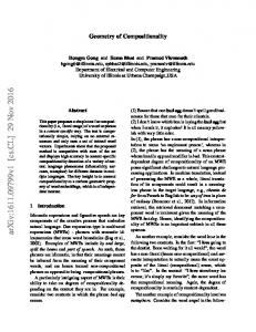
In previous Sections, we limited our study to IPs which consume and produce the same amount of data on each input and output. Now, we assume that each IP can produce and consume a different amount of data, which is also equivalent for instance to specify the relative sample rates of each IP. This model is known as Synchronous Data Flow (SDF) which is a special case of Petri nets including the Marked/Event Graph sub-class that we have introduced in Section 2. Marked/Event Graph is also called Homogenous SDF graph because exactly producing/consuming one token on each output/input respectively. Previous works achieved by E. Lee et al. about SDF [12,11] shown that this model can be statically scheduled. But most of the results found was targetting implementations on single or multiple processors with hard real-time constraints, while minimizing different metrics such as for example buffering requirement between each IP, size of the schedule. We attempt in this Section to show how this model can be used on the SoC. The SoC in this Section is abstracted as an SDF Graph: each IP becomes a node, each datapath becomes a directed link. IP are annotated in input with the number of data consumed and in output with the number of data produced during the same time span. Figure 7 depicts such a SDF graph. input
output 2 1
1
1 1 2 Fig. 7. SDF Graph with consistent sample rates
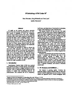
E. Lee gives a mathematical formula to validate the “consistency of samples rate”: which says intuitively that it exists a schedule for each node such that the sum of produced data is equal to the sum of consumed data on each directed cycle of the graph. Such SDF graph is called safe: there is no strong acccumulation nor starvation of data. The system is thus seen as “synchronous” on a global period (k-periodic fashion). There is also another interesting strong result that says globally how much times a node is fired during a global period. Figure 7 shows an example of a SDF graph with consistent sample rates, the next Figure 8 depicts the same graph with the global amount of firing each node is activated during the global period. However, in the case of strongly connected SDF graph there is no strong theo14
Boucaron and Millo input
output 2 1
1
1
2 1 1 1 2
Fig. 8. SDF Graph with its schedule
ritical result that ensures liveness just like in the case of Event/Marked Graph. We known the minimum amount each node should fire during a whole period but not the explicit schedule for each node taking care of the initial marking. Moreover, we do not known the size of the buffering places needed between each IP. To solve those issues we have to simulate in a kind of model-checking fashion, starting with an initial placement of tokens (called delays in SDF terminology) until reaching the same global state, that ensures that we are reaching a periodic regime: while simulating we can compute the schedule of each node using the ASAP firing rule and also find the size of each buffering place between each IP. The schedule of each node is denoted as an ultimately k-periodic word. The SDF model can be seen as a “bread” like model while WMG can be considered as a “depth” oriented one: to introduce the latency metric in the SDF model, we can also use the same kind of Transportation Nodes and additional places as described in Section 2. Just like the WMG model, due to the ASAP firing rule, schedules of nodes will be shifted by a given amount because lengths of different reconverving pathes are not strictly equal in general. In this Section, we wanted to recall the SDF model because while being a generalization of the Event/Marked Graph, this model leads to the same kind of k-periodic behaviour provided safety and liveness are shown. It is known that a safe SDF graph can be “expanded” in a Event/Marked Graph. Then we can also link such expanded SDF graph within a synchronous or GALS framework provided that all correctness criterions described before in Sections 4, 5 respectively are ensured.
15
Boucaron and Millo
7
Conclusion
Our previous works [2,3] explain how starting from a synchronous Latency Insensitive Design derived from a synchronous specification, we can then create a Static Scheduled IP (SSIP) having the same behaviour and the same throughput than the Latency Insensitive one. This paper introduces what conditions are needed such that we compose such Static Scheduled IP with Synchronous Circuit, in a Globally Asynchronous Locally Synchronous framework and also in the case of Multi-Rate components a ` la SDF. Those conditions are defined, enumerated using external “public” properties of the SSIP. The goal of this paper is to show SSIP are compositional without changing its internal net. The most easy composition is the one with the GALS framework, because by hypothesis a SSIP is patient: clock-gating does not affect its behaviour. Since a GALS is also sharing the patience property, it is easy through the usual hand-shake protocols to ensure the correct behaviour: we are just stretching time on time due to clock rate and throughput of each GALS component; we can use such hand-shake protocol while limiting the number of ressources required for buffering. The composition in the case of a fully-synchronous framework is more complex, because a Synchronous Circuit is not patient. We need a lot of buffering in order to absorb advance/retard of the SSIP versus the synchronous environment, we found an upper bound of such buffering which is dependent on k (is the number of occurences of firing of the SSIP during a period of length p). The initialization of the global system is more difficult, we have to delay the startup of downward Synchronous Circuits until the SSIP is reaching its stationary regime: because the SSIP can be slower or faster than the Synchronous Circuit during initialization, we may add some buffering in the FIFOs on both ends of the SSIP to absorb the local lack/burst of throughput. Note that original Latency-Insensitive Design (LID) presented in [5] is compositional with synchronous or GALS components under the same condition than SSIP concerning clock signal requirement. If these conditions are not present, LID can be used on the whole system for its composition. Further Topics During initialization throughput can be slightly faster/slower and buffer resources may be used in initialization only, and not in the periodic phase of the SSIP. Shorter initialization and/or more evenly “balanced” from the throughput point of view are needed to minimize buffer resources. It is also possible to use more evenly “balanced” schedules, to minimize the number of buffer resources used below the periodicity bound. In this modeling framework there is no alternative choice behaviours. It should be interesting to introduce modes as limited control structures.
16
Boucaron and Millo
References [1] Fran¸cois Baccelli, Guy Cohen, Geert Jan Olsder, and Jean-Pierre Quadrat. Linearity: an algebra for discrete event systems. John Wiley & Sons, 1992.
Synchronization and
[2] Julien Boucaron, Jean-Vivien Millo, and Robert De Simone. Latency-insensitive design and central repetitive scheduling. In Formal Methods and Models for Co-Design, 2006. MEMOCODE ’06. Proceedings. Fourth ACM and IEEE International Conference on, pages 175– 183, Piscataway, NJ, USA, 2006. IEEE Press. [3] Julien Boucaron, Jean-Vivien Millo, and Robert De Simone. Formal methods of scheduling for latencyinsensitive designs. EURASIP journal on embedded system, 2007 (not yet published). [4] Jacques Carlier and Philippe Chr´etienne. algorithmes. Masson, Paris, 1988.
Probl` eme d’ordonnancement: mod´ elisation, complexit´ e,
[5] Luca Carloni, Kenneth McMillan, and Alberto Sangiovanni-Vincentelli. Theory of latency-insensitive design. IEEE Transactions on Computer-Aided Design of Integrated Circuits and Systems, vol. 20(no. 9):pp. 1059–1076, 2001. [6] Luca .P Carloni, Keneth L. McMillan, and Alberto .L. Sangiovanni-Vincentelli. Latency insensitive protocols. In N. Halbwachs and LNCS 1633 D. Peled, editors, Proc. of the 11th Intl. Conf. on ComputerAided Verification (CAV), pages 123–133. UC Berkeley, Cadence Design Laboratories, July 1999. [7] Mario R. Casu and Luca Macchiarulo. A new approach to latency insensitive design. In DAC ’04: Proceedings of the 41st annual conference on Design automation, pages 576–581, New York, NY, USA, 2004. ACM Press. [8] Tiberiu Chelcea and Steven M. Nowick. Robust interfaces for mixed-timing systems with application to latency-insensitive protocols. In Design Automation Conference, pages 21–26, 2001. [9] Albert Cohen, Marc Duranton, Christine Eisenbeis, Claire Pagetti, Florence Plateau, and Marc Pouzet. N-synchronous kahn networks: a relaxed model of synchrony for real-time systems. In POPL ’06: Conference record of the 33rd ACM SIGPLAN-SIGACT symposium on Principles of programming languages, pages 180–193, New York, NY, USA, 2006. ACM Press. [10] Edward A. Lee and David G. Messerschmitt. Static scheduling of synchronous data flow programs for digital signal processing. IEEE transactions on computers, C-36(1):24–35, 1987. [11] Edward A. Lee and David G. Messerschmitt. Synchronous data flow. Proceeding of the IEEE, vol. 75(no. 9):pp. 1235–1245, 1987.
17