Combined Shear/Compression Structural Testing of Asymmetric Sandwich Structures by B. Castanié, J.J. Barrau, J.P. Jaouen and S. Rivallant ABSTRACT—Asymmetric sandwich technology can be applied in the design of lightweight, non-pressurized aeronautical structures such as those of helicopters. A test rig of asymmetric sandwich structures subjected to compression/shear loads was designed, validated, and set up. It conforms to the standard certification procedure for composite aeronautical structures set out in the “test pyramid”, a multiscale approach. The static tests until failure showed asymmetric sandwich structures to be extremely resistant, which, in the case of the tested specimen shape, were characterized by the absence of buckling and failure compressive strains up to 10,000 µ strains. Specimens impacted with perforation damage were also tested, enabling the original phenomenon of crack propagation to be observed step-by-step. The results of the completed tests thus enable the concept to be validated, and justify the possibility of creating a much larger machine to overcome the drawbacks linked to the use of small specimens. KEY WORDS—Composite sandwich structures, shear/ compression testing
Introduction Asymmetric sandwich structures are a new technology applicable in the making of light aeronautical structures. An asymmetric structure differs from a conventional sandwich structure in its geometry and design. As shown in Fig. 1, such a structure has three distinct zones: a thick, monolithic zone with a bolted junction, a tapered transition zone, and finally the purely asymmetric sandwich composed of a relatively thick skin called “the working skin” and a second skin, the “stabilizing skin”, which is always thin. For the aeronautical applications studied, the skins and the monolithic zone are made of graphite-epoxy laminates and the sandwich core of Nomex Honeycomb. The stabilizing skin is made up of just two layers of carbon fibers. Unlike conventional sandwich structures, this type of structure is not well suited to taking bending loads but it can be used in the making of light aeronautical structures for helicopters, light aircraft, etc. These structures thus take only membrane-type loads via the working skin. The core and the stabilizing skin ensure buckling stability under the
B. Castanié (
[email protected]) is an Assistant Professor and S. Rivallant is a PhD, Institut de Génie Mécanique de Toulouse (I.G.M.T.)/Supaero Laboratoire Structures, BP 4032 31055 Toulouse, France. J.J. Barrau is a Professor, I.G.M.T./Université Paul Sabatier, Bat 3PN, 31062 Toulouse, France. J.P. Jaouen is an Engineer, Eurocopter France, 13700 Marignane, France. Original manuscript submitted: July 17, 2003. Final manuscript received: July 6, 2004. DOI: 10.1177/0014485104047607
© 2004 Society for Experimental Mechanics
dimensioning loads of compression and shear. Because the neutral surface of the sandwich is not the same as the load application plane (mid-plane of the working skin), a tensile/compression loading also generates a bending moment, which is very sensitive to the deflection of the sandwich. This means that the behavior of this type of structure is geometrically nonlinear.1,2 Few, if any, studies of this type of structure exist3 except in the linear field.4 Like all aeronautical structures, the certification of asymmetric sandwich structures depends on a series of tests. In composite structures, since “the material is not pre-existent to the part itself”, a multilevel approach is necessary.5 This type of approach, first used for metal aeronautic structures, is set out in a “test pyramid” in Europe6 (see Fig. 2). At the base of the pyramid are the conventional tests of the characterization of materials on the scale of the ply. The second level tests structure-type specimens, representing the technology to be qualified but not specific to a particular zone or aircraft. At the upper levels are tests of technological details specific to a zone or an aircraft (junction, windows, etc.), tests of subassemblies (spars, wing boxes, etc.) and final assemblies (nose cap, wing, whole aircraft). This multilevel approach is similar in the USA7 or in Russia.8 This paper deals with an original test of the second level under combined compression/shear on non-specific asymmetric sandwich specimens, impacted and pristine. Structural Tests on a Sandwich Sample Existing Tests With the framework of the pyramid test method for the certification of aeronautical structures, the second-level tests must represent dimensioning cases of buckling under compression or shear. In the case of pure compression (Fig. 3), the sandwich panel is mounted on a support in a standard test machine. The variants mainly concern the management of the boundary conditions on the vertical surfaces (U-beams with grease, knives, attached stiffeners, etc.) and the technologies used for introducing the loads into the specimen.1,7–9 Some recommendations can also be in the ASTM norm C364-94. The practical difficulties of this type of test, pointed out by Hoff and Mautner in 1948, are the mastering of the boundary conditions, and the correct introduction of the compression load on the middle plane of the specimen.10 A poorlycontrolled introduction actually causes a nonlinear geometric behavior1,11 even for symmetric sandwich structures.
Experimental Mechanics • 461
Membrane Loadings : Compres sion S hear
Stabilizing Skin Monolithic area
C entral area Neutral line
R ampdown region
Working s kin
Fig. 1—Asymmetric sandwich structure technology
Test on the “Gazelle” helicopter
Airbus A310 Wing Test
Components Full-S cale Te sti ng
e, l ag f t se ir cr a Fu A e tir En
Fou rth L e v el
Subcompone
So m e Parts
nts
Sp e cif ic C ar
Th ird L eve l
Spe c ifi c
S eco n d L e vel Doz ens of S
First Lev el
H undreds
W
in s r t i ch e s w In nd Sa
D etails
D oze ns of S p eci m ens
n bo
ox gB in
E lements
peci mens
Non Spe cific
Sa
w nd
h ic
at pl
e
Coupons
o f S p eci m en s
N on S pe
ci fic
s on up o C
Fig. 2—Pyramid test method (based on Rouchon6 )
Most tests of shear buckling are performed using a deformable square, as shown in Fig. 4. The principle consists of applying a load along the square vertical diagonal. The frame will then transmit this load to the specimen, as well as a compression load along the horizontal. The stress field in the specimen is then theoretically a pure state of shear. The loads are transmitted from the frame to the specimen by bolting. This technology was first developed in the US Forest Product Laboratory to test plywood12 and is also defined by ASTM norm D2719. The method is widely used in the aeronautical fields and also for testing naval structures.1,13,14 Nevertheless, a uniform stress field in the sample can be obtained only with an adequate design. A poorly made frame will cause excessive stresses in the corners and premature local failures. The real position of the articulated joint in the corners has a non-negligible influence in the stress field in the sample.13 462 • Vol. 44, No. 5, October 2004
Zagainov and Lozino-lozinsky8 recommend local cuts in the corners of the sample and articulated joints centered on the corners. These two second-level structural tests produce reliable results for determining the buckling stresses in compression or shear. They have the advantage of being workable on standard test machines, with relatively basic test rigs. However, especially for the pure compression test, the boundary conditions only imperfectly represent the junction technology and the results are therefore very conservative. Because aeronautical structures are submitted simultaneously to compression and shear, the test pyramid logically imposes complementary tests under this type of combined load. Apart from a few particular off-axis tests (obtained simply by balancing the axis of the sample in the two classical tests), these tests require the use of at least two actuators © 2004 Society for Experimental Mechanics
Vertical Compression/Traction Actuators Fixed Frame
Stiffener
A
A
S ample
C C
Knives
U-guide
B
B
Moving Fixture
Shear Actuator
Horizontal Compression/Traction Actuators T YP E 1
T YP E 2
Fig. 5—Combined test rigs
Fig. 3—Compression test rig
Sample Joints
Loading
Theoretical Frame
stress field
Fig. 4—Deformable square
and the design of specific machines. Complex and expensive to design and build, the few existing machines in the world are mainly in aeronautical testing and research centers or at aircraft manufacturers whose results are rarely made public. Nevertheless, the technical solutions used can be divided in two categories. The first consists of directly reproducing the compression/shear loads by means of actuators. Wolf and Kossira15 have presented a machine for testing fuselage skin panels (see Fig. 5, type 1). The upper and lower parts of the specimen are housed with rigid fixtures. The lateral sides are fixed by 44 silent-blocks to enable shear to be introduced while compression is applied simultaneously. The specimen is loaded with shear by six actuators. Two horizontal actuators (A) produce a load on the upper horizontal fixture. Four vertical actuators (B) work in pairs in opposite directions to transmit a load via a lever to the two lateral beams. In this way, three of the spec© 2004 Society for Experimental Mechanics
imen’s four sides are solicited and the shear stress is carried out correctly. Four more actuators (C) enable compression to be introduced into the assembly. Finally, the beams making up the frame are joined together with articulated joints. Wolf and Kossira15 do not mention the advantages and drawbacks of this method, but it is obviously technically complex and requires operating 10 actuators. Another machine that can carry out both biaxial tensile/compression and shear was developed for structures used in the space industry.16 The specimen has a maximum crosssection of 700 × 1000 mm. The lower fixture is intentionally mounted free to avoid causing interference between loads. The actuators are controlled by position sensors, thus avoiding any rotation of the free fixture and the introduction of parasite loads. Unlike the machine described previously, in which three of the four sides of the frame introduce the shear stress, this machine uses just one of the sides to introduce the same type of load, and it can be observed that the loading is closer to bending with shear than to pure shear. In Fig. 6, the second most frequent test method uses a box structure, of which one or more faces is replaced by the test specimen. As early as 1947, Peters17 submitted a squaresectioned box to torsion and bending and was thus able to identify an experimental curve of the compression/shear buckling of the specimens which made the faces of the central part of the box. More recently, Klein18 used a box structure fixed to a support at one end and loaded under bending/torsion at the other end by means of two actuators. When the two actuators are activated symmetrically, the box is loaded in bending. In this case, the lower box face, where the sample is mounted, is submitted to tensile or compression stresses (and also to transverse shear). When the two actuators are activated antisymmetrically, the box is submitted to torsion and the specimen which acts as a membrane take shear. Because the actuators are controlled, the two types of loading can be combined. The laminated or sandwich composite specimen is 1 m long and is bolted to the box by 180 bolts and a resin interface. It ensures the real boundary condition very close to the “all-clamped” theoretical model, since the box itself is very rigid. Klein claims to have obtained good results for determining critical buckling loads for sandwich plates 6– 8 mm thick. He points out that it is impossible to determine the stress flows entering the sample because of the numerous structural redundancies. However, the flow is measured in situ by equipping the specimen with 150 strain gages set out in a grid pattern. To our knowledge, other machines do exist and are being used at large aircraft manufacturers or in aeronautical test centers (CEAT, Toulouse, France, and NASA Experimental Mechanics • 463
Box beam
2
1
7
F
9
F 8 6
or
Sample
T
Actuators (x2)
T
Fig. 6—Compression/shear test with a box structure (based on Peters17 ) 3
4
5
10
Fig. 7—I.G.M.T./Supaero test rig
Langley19 ); however, on account of the strategic importance of this type of test, little information is published. It should also be noted that naval designers have developed second-level tests on the working methods of their structures, i.e., under pressure20 or under compression/pressure.21 This selected bibliography shows some standard and specific test methods used for composite sandwich structure tests. There are two reasons why it is essential to develop such methods of complex-load testing for new technology composite structures. First, a multilevel approach is needed with structural tests formalized in the test pyramid. Secondly, there is a lack of experimental results in the field of combined loads, which require important security coefficient to be taken, despite the existence of quadratic laws of interaction.22 Consequently, with a view to developing asymmetric sandwich structure technology, a new, specific test method had to be developed, as described in the next section. I.G.M.T./Supaero Test A box structure was chosen, as its upper and lower faces reproduce in the most realistic and simple way the working mode of aircraft asymmetric sandwich structures in terms of loading and boundary conditions (see Fig. 7). The test rig is made of an aluminum alloy box (1) and two crossing steel I-beams (3). The technological specimen (2) is a carbon-skin sandwich bolted to the central part of the upper surface of the box. The box is fixed at the ends of the two crossing I-beams with two knee joints on two supports (4). The two other ends of the I-beams are fixed with knee joints to the torsion actuators (5). Two support beams (6) hold the bending actuators (7) whose other ends are joined to the ends of the box (2).The whole assembly stands on a surface table (8). The dimensions of the rig obtained are length 2400 mm, and section 248 × 220 mm. The I-beams are 1170 mm long between their fixation points. The methods of load introduction are different from those proposed by Peters17 and Klein18 and the design is adapted to the case of asymmetric sandwiches. When the actuators (7) apply an upward vertical load F, the box is submitted to four-point bending, and the central zone between the two crossing I-beams (3) to pure bending. Consequently, the specimen forming the upper surface of the central box is submitted to compression without transverse shear. When the actuators apply a vertical load T , the central part of the box is submitted to shear. When the actuators are activated simultaneously, the specimen is submitted to a com464 • Vol. 44, No. 5, October 2004
Rampdown
Longitudinal axis of the box
Junction zone (Monolithic)
Overall Dimensions 248 x 306 mm Asymmetric sandwich zone (200x200 mm including rampdown)
Fig. 8—Bird’s-eye view of specimen
pression/shear loading. This simulates the working method of helicopter tail booms, which are mainly submitted to bending during pull out or hard landing, and to torsion and bending caused by the antitorque rotor. Design, Manufacturing and Development of the I.G.M.T./Supaero Test DESIGN This type of assembly has two main design targets: to obtain the stress field that corresponds as closely as possible to theory and to make static failure tests on the carbon specimen without breaking the test assembly itself. In Fig. 8, specimen dimensions of 200 × 200 mm were defined. Overall dimensions are 248 × 306 mm including the monolithic load transfer zone. The specimen is bolted to the test rig by 42 (d = 5 mm) screws and 16 (d = 4 mm) screws. During the design phase, a linear finite element model was developed, using Kirchhoff plate elements for the box (see Fig. 9). It can be demonstrated that, in the linear computation case, the working skin takes about 95% of the strain energy of the sandwich.1 The core and the stabilizing skin are efficient only to prevent global buckling. Thus, only the working skin of the asymmetric sandwich is modeled by an equivalent orthotropic plate. Using this modeling, the conceptual design of the installation has been improved significantly. The following key-point results were particularly observed.1 © 2004 Society for Experimental Mechanics
BOX AXIS
2
Deformed scale: 28
1
σ22 : 12% τ12 : 0.4%
LAMINATE N° 1 :
Center :
σ22 : 1.9% τ12 : 0.03 %
IPN s ide
σ22 : 7.5% τ12 : 7.2% σ22 : 0.5% τ12 : 5.3%
S ide panel edge
σ22 : 28 % τ12 : 1.2 %
Fig. 9—Deflection field of the box under combined loading1
LAMINATE N° 2 :
σ22 : 0.09 % τ12 : 0.1 %
Center :
σ22 : 8 % τ12 : 0.13 %
IPN s ide
σ22 : 18 % τ12 : 19.5 % σ22 : 5.4 % τ12 : 16 % LOCAL BENDING MOMENT
S ide panel edge
σ22 : 0.13 % τ12 : 0.17 %
COMPRESSION STRESS FLOW
σ22 : 26% τ12 : 1%
LAMINATE N° 3 : IPN s ide
Upper skin of the box
Working skin of the specimen Upper I-beam boom
σ22 : 17.5% τ12 : 18% σ22 : 5% τ12 : 14.8%
W eb of the I-beam
Fig. 10—Compression flow route
• In the first design loop, the torsion was introduced by triangular arms. The finite element model showed that the stress concentration in the test sample and in the box can be diminished by using I-beams. • The load introduction boxes must be made global and local buckling proof by using stiffener and using steel for the upper skin. • In Fig. 10, the compressive loading is transferred from the upper skin of the box to the specimen via the upper boom of the I-beams. The different shifts of the neutral line generate local bending moment. After testing several designs, the boom of the I-beam must be rigid enough (8 mm) to minimize these local bending effects. It is not a drawback if local stiffness is much higher than that of the specimen since the junction is situated in the monolithic zone of the specimen, which is itself extremely stiff. Once the design has been finalized, the finite element model should enable an a priori study of the stress fields obtained in the working skin of the specimen. Numerical compression and shear tests were carried out for three different stacking sequences of the working skin issued from Eurocopter’s own technology. Figures 11 and 12 show the numerical secondary stress rates (i.e., plane stresses which are not the nominal stress) compared to expected nominal stress (σ11 in compression and τ12 in shear). In the numerical compression test (see Fig. 11), the variation of stress σ11 on the plate is not over 10%. The local rate of © 2004 Society for Experimental Mechanics
Center :
σ22 : 6.4% τ12 : 0.1 %
S ide panel edge
σ22 : 0.03 % τ12 : 0.05 %
Fig. 11—Secondary stresses obtained in the compression numerical test
2
BOX AXIS 1
σ11 : 1.6% σ22 : 0.1%
LAMINATE N° 1 : (variation of τ12: 10% )
Center :
σ11 : 0.2% σ22 : 0.1%
IPN side
σ11 : 48% σ11 : 101% σ22 : 0.87% σ11 : 59%
S ide panel edge
σ11 : 0.9% σ22 : 0.016 %
LAMINATE N° 2: (variation of τ12: 28% )
Center :
σ11 : 0.17 % σ22 : 0.17 %
IPN side
σ11 : 16% σ11 : 33% σ22 : 1.8%
S ide panel edge
σ11 : 1,2% σ22 : 0.2%
LAMINATE N° 3: (variation of τ12: 17% )
σ11 : 3.8% σ22 : 1.2%
σ11 : 0.1% σ22 : 1.5% Center :
σ11 : 0.2% σ22 : 0.13 %
IPN s ide
σ11 : 24% σ11 : 45% σ22 : 16% Side panel edge σ11 : 23%
σ11 : 0.9 % σ22 : 1.1%
Fig. 12—Secondary stresses obtained in the shear numerical test
Experimental Mechanics • 465
secondary stress on the corners remains under 26%, and usually under 20%. The rate of secondary stresses in the center of the plate is always less than 8%. In the numerical shear test (see Fig. 12), the variations of the nominal stress on the whole specimen are 10%, 28%, and 17% for specimens 1, 2, and 3, respectively. The quality of the tests is good for the first stacking sequence, mediocre for the second, and average for the third. A phenomenon of concentration of stresses appears in the corners probably due to the greater stiffness of the monolithic zone. Nevertheless, since the central zone is not perturbed and Eurocopter’s technology prevents any risk of local failure, this phenomenon does not jeopardize the success of the test. It can be observed that secondary stresses are minimized when the loadings applied by the test rig agree with the stacking sequence design (predominance of an orientation at 0◦ or 45◦ ), and consequently “the tests are better when the laminates are tested in accordance with their technological purpose.” The above observation is typical of this type of structural test. It would appear that results are influenced by the stiffness, in torsion or bending, of the assembly formed by the central aluminum box and the specimen. When specimen stiffness is optimal for the loading case, stresses are distributed uniformly in the working skin. On the other hand, when specimen stiffness is reduced, the stress flows are more concentrated on the more rigid zones of the central box, generating a perturbed stress field in the working skin. Therefore, the stiffness of the aluminum alloy side panels of the central box must be comparable to those of the specimens so that the stress flows are distributed evenly in the central box. The side panels and the corner beam, which support the specimen, might become plasticized during tests, due to very high failure strain of the carbon laminates. This condition is required for carrying out failure tests. Because they remain permanently deformed after loading, they must be replaced regularly. Moreover, because the boundary conditions are close to the clamped mode on the four sides, it is impossible to obtain a pure stress field at the center of the specimen. However, the rate of secondary stress is not more than 2% for standard configurations. Although stress concentrations also appear in the corners of the specimen, asymmetric sandwich sample technology does take this phenomenon into account by strengthening local areas. In conclusion, this linear finite element study enables the design to be improved significantly. It has been demonstrated numerically that the test design is viable, which was a requisite. The loading method, which causes an “out-of-plane” displacement of the torsion arms, would not appear to perturb the stress field in the specimen. The philosophical side to this type of “structure” test also appeared more comprehensible. MANUFACTURING Manufacturing and design details can be found in Castanié.1 As in Fig. 13, the test rig was equipped with a hydraulic loading system using manually operated pumps. Thanks to this simple system, displacements can be imposed, a pertinent operation when buckling is studied. This system was chosen in preference to an automatic one since the pressure is instantaneously adapted to the residual strength of the specimen after the breaking, which is quasi-explosive. The specimen thus remains in good condition for a post-mortem 466 • Vol. 44, No. 5, October 2004
Fig. 13—General view of the I.G.M.T./Supaero test rig
analysis. Loading is performed step by step. In Fig. 7, the load applied is measured by four load sensors (9), (10) attached to the four actuators. Nevertheless, during the experiment, the static equilibrium of the box must be adjusted because a coupling effect exists between bending and torsion.1 This phenomenon is due to the rotation during the torsion loading of the fixing points of the bending actuators. DEVELOPMENT The viability of the test rig was experimentally verified in two ways: quantitatively with a 2024 plate fitted with strain gages and bolted in the place of the sandwich sample, and qualitatively with a photoelastic study of the first sandwich specimen at the lower loads. A quantitative study was not performed because of the high strain level reached at the working skin failure. The photoelastic plate used is not able to follow the high range of strains involved and, quickly, the number of fringes increases and a uniform gray color appears. The 2024 plate was loaded in compression and then in shear. In Fig. 14, the expected compression stress σ11 is 26 MPa in the center of the plate. The variation of σ11 between the measurement points does not exceed 14% except for the bottom left-hand rosette where σ11 of 20.2 MPa occurs. The maximum level of secondary stresses σ22 (transversal compression) is 6% in the center and the maximum level of τ12 (shear) is 12.3% at the edges. These results are similar to those obtained by numerical testing and show that the test rig is suitable for carrying out compression tests. The first torsion tests of the test rig revealed high local stresses in the corners and an abnormally high rate of secondary stresses throughout the plate. The latter are due to the asymmetric loading of the box during the torsion, causing the corners of the specimen to move out of their plane. However, the plate naturally tends to remain horizontal and to become unstuck locally. This phenomenon was also found with the finite element model by setting the node at the corner of the specimen free. The technological solution to this problem consisted of adding very stiff steel plate, 10 mm thick, adjusted on the face in contact with the specimen and drilled with fixture hole (see Fig. 15). These plates force the specimen to follow the box deflection, which creates a more homogeneous stress field. Once this system was set up, a shear test was carried out, whose expected shear stress τ12 is 22 MPa in the center of the © 2004 Society for Experimental Mechanics
BOX AXIS
BOX AXIS 2
σ22 : 5.5% τ1 2 : 8.8%
σ22 : 5.4% τ12 : 10.2% σ22 : 6.3% τ12 : 12.3%
1
σ22 : 4.8% τ12 : 6.6%
S ide panel E dge
σ11=-22.7 MPa
σ1 1=-22.7 MPa
σ1 1=-22.8 MPa
I-beam E dge
σ11 : 0% σ2 2 : 11.1%
I-beam E dge
σ11 : 47% σ22 : 5%
σ11 : 31% σ2 2 : 0%
S ide panel E dge
τ12 =18 MPa
τ12 =19 MPa
τ12=19 Mpa
I-beam E dge
τ1 2=23 MPa
σ11 =-23.58 MPa
σ2 2 : 0.2% τ1 2 : 2.4%
σ1 1 : 21% σ22 : 4.3%
σ11=-26 MPa σ11 =-25.2 MPa
σ2 2 : 2.3% τ12 : 6%
σ2 2 : 6% τ12 : 3.2%
τ1 2=23 MPa
τ12=22 MPa
σ1 1 : 34% σ2 2 : 4.3%
I-beam E dge
σ1 1 : 13.6% σ22 : 4.5%
τ12 =23 MPa
σ11 =-20.2 MPa
σ11 : 7.4% σ2 2 : 8.7%
τ1 2 =21 MPa
2
σ22 : 7.4% τ12 : 7.4%
S ide panel E dge
A ctuator load : 3000 N
1
Fig. 14—Experimental validation of the test rig: compression test with an 2024 aluminum alloy plate
I-beams
σ11 : 38% σ22 : 19%
S ide panel E dge
A ctuator load : 3000 N
Fig. 16—Experimental validation of the test rig: shear test with an 2024 aluminum alloy plate
Specimen
Uniform color at the center of the test plate
Steel plates
Photoelastic plate
The area of stress concentration due to the bolted zone is small
Side panels Cornerbeams
Stiffeners
Fig. 15—Design, assembly of central box and addition of steel plates
plate (see Fig. 16). The variation of τ12 at the measurement points does not exceed 18%. The level of secondary stresses σ11 and σ22 reaches 74% for one rosette in one corner. Nevertheless, the values obtained by finite element modeling (with an orthotropic skin) also reach high levels (up to 101%) and the secondary stress level does not exceed 14% in the center. In conclusion, these results show that, all in all, the test rig is suitable for shear tests. Although the aluminum plate was installed without incident, installation of the sandwich plate proved difficult. Indeed, since the panel was very stiff in bending, the flexibility of the plate did not compensate the geometrical manufacturing defaults of the test rig and generated excess stresses throughout the working skin. To compensate these manufacturing and assembly related geometrical defects (offset and slope of the I-beams), resin was applied on the central box and the plate was tightened slightly. The plate’s installation on the rig then yielded only residual strain of 300 µ strain in the center (shear test 2), i.e., less than 3% of the ultimate failure strain. The resin has the drawback of penetrating the hole and sticking to the screws, which sometimes hindered easy removal of the specimen. The problem could be solved by using studs. A photoelastic plate was stuck onto the first sandwich specimens to analyze the strain fields in the working skin. © 2004 Society for Experimental Mechanics
Fig. 17—Photoelastic study: strain field under compression
Figure 17 shows a photograph of a weakly loaded specimen. The uniform color on the test zone shows that the deformation and therefore the stresses are quasi-uniform and that the influence from bolting is limited to the monolithic zone. After addition of the steel plates, the test rig was deemed operational. However, during the first shear test, failure occurred along the line of bolts in the monolithic zone (cf. Fig. 17). In fact, the aluminum 2024 alloy side panels are not stiff enough, which causes a substantial displacement of the specimen out of its plane as well as an overlarge concentration of stresses. This is solved by simply using steel plates instead, allowing proper failure to occur under shear loading. Results and Discussion Eurocopter France supplied asymmetric sandwich structure specimens with typical technological characteristics in their monolithic zones, rampdown, and central part. Results are given here for tests on 12 specimens, half of which have a 4-ply carbon working skin 0.9 mm thick, and half having a technological minimum 2-ply carbon working skin 0.52 mm. Six other 4-ply specimens were impacted in the center of their working skin and tested until failure occurred. The monolithic zones and rampdown are designed using Eurocopter’s own technology. Strain gages were attached to Experimental Mechanics • 467
various points of the skin1 and systematically to the centers of both skins in non-impacted tests.
0
Analysis of the Behavior of Asymmetric Sandwich Structures The responses of the two-ply specimens are described in this paragraph. Other results relating to the 4-ply specimens can be found in Castanié.1 BEHAVIOR IN COMPRESSION To analyze behavior in compression, Fig. 18 shows a plot of the evolution of the strain in the box axis (0◦ ) at the centers of the working and stabilizing skins. 468 • Vol. 44, No. 5, October 2004
4000
6000
8000
10000
12000
14000
16000
Stabilizing Skin
S trains train) Strains (µ(µs strains)
-2000 -3000 -4000
Gage 0° WS 2Ply-1 Gage 0° SS 2Ply-1 Gage 0° WS 2Ply-2
-5000
Gage 0° SS 2Ply-2
-6000 -7000
COMPRESSION TEST OF 2-PLY SPECIMEN
-8000
Working Skin -9000
Fig. 18—Behavior in compression of asymmetric sandwich structures
8000
SHEAR TEST OF 2-PLY SPECIMENS
6000
4000
Strains (µ strains)
The failure strain values obtained correspond to the last load increment before failure and are therefore conservative (Table 1 for compression, Table 2 for shear, and Table 3 for combined loads). Globally, the directions of the main strains at the level before failure conform to the load applied (0◦ (box axis) for the compression and +/–45◦ for shear). This important result confirms that the test rig is able to apply the type of load required. All but one of the specimens broke by brittle failure of the working skin of the asymmetric sandwich and along one of its main stress directions. The first 4-ply specimen tested in shear broke near the bolts in the monolithic zone. The test rig was then readjusted. At failure, the main strains obtained are very high, sometimes reaching –12,500 µ strains, stabilized value, this being close to pure compression values obtained by testing parallelepiped specimens. The observed absence of global buckling may be due to the small dimensions of the test zone, to the all-clamped boundary conditions, and also to the real technological conditions on helicopters. The analysis of failure patterns shows not only that asymmetric sandwich technology has high intrinsic resistance, but also that the test rig can apply static loads up to breaking point without deteriorating. It is important to note that these tests and the results obtained for combined load do not lead to any conclusions about whether or not classical failure criteria are valid (maximum strain, hill, etc.). Indeed, failures are of an explosive nature and their point of origin is not known. Nevertheless, they may well be triggered at the edge of the plate or at a ply end whose experimental stress level is not known. The ultimate failure strains are quite highly dispersed (up to 20% for same-type specimen). Unlike material type tests where dispersion is under 5%, tests on composite structures are naturally prone to larger dispersions, even as high as 30% for compression tests on launcher interface cones.8 The latter are due, on the one hand, to the composite structure itself: variation in characteristics of the materials, in polymerization, in ply direction, in specimen cutting, and in defects in hole drilling. On the other hand, these variations can result from the test rig setup: manual tightening of the screws, residual deformations, non-standard manufacture of replacement parts, and manual adjustments. Finally, the actual failure can be attributed to a concentration of stress at any structural discontinuity such as ply stop or extremity of the tapered sandwich, and both the initiation criteria and the sensitivity of these zones are not well known.
2000
-1000
Tests on Non-Impacted Plates ANALYSIS OF STATIC FAILURES
L O A D(daN) (N)
0
+45° 2000 -45°
Load (N) 0 0
200 0
400 0
600 0
800 0
1000 0
1200 0
14000
-2000 Gage +45° WS 2-Ply 1 Gage -45° WS 2-Ply 1
-4000
Gage +45° SS 2-Ply 1 Gage -45° SS 2-Ply 1 Gage +45° WS 2-Ply 2
-6000
Gage -45° WS 2-Ply 2 Gage +45° SS 2-Ply 2 Gage -45° SS 2-Ply 2
-8000
Fig. 19—Behavior in shear of asymmetric sandwich structures (WS, working skin; SS, stabilizing skin)
The working skin has a quasi-linear response whereas there is notable nonlinearity for the stabilizing skin. Tests on asymmetric sandwich beams have shown that the stabilizing skin can be loaded with tensile stress.1 In this configuration, the clamped boundary conditions on the side edges tend to attenuate this phenomenon and the stabilizing skin remains in compression at low levels. This caused the failure to occur in the working skin. BEHAVIOR IN SHEAR To analyze behavior in shear, Fig. 19 shows a plot of the evolution of the strains measured by two rosettes at +/–45◦ at the centers of the working and stabilizing skins. Both skins have a quasi-linear response. This can be explained by the fact that geometrical nonlinearity is due to coupling the sandwich deflection and the load. In shear, moreover, the deflection is very small and no nonlinear coupling is thus likely to appear. It can be seen that strain plummets in the stabilizing skin at the penultimate load increment during both tests. This dramatic fall could indicate that a breakage of either the core or the stabilizing skin occurred before failure of the working skin. BEHAVIOR UNDER COMBINED LOADS To analyze behavior under combined loads, Fig. 20 shows a plot of the evolution of the strains measured by gages po© 2004 Society for Experimental Mechanics
TABLE 1—MAIN COMPRESSIVE STRAINS AT THE CENTER OF THE WORKING SKIN JUST BEFORE FAILURE (UNITS ARE µ STRAINS) AND WORKING SKIN BREAKING LINES
SPECIMEN
4 P L Y- 1
4 P L Y- 2
DIRECTION
2°
1.58°
ε 1 (µstrains)
-10467
-12510
ε 2 (µstrains)
1391
1191
2 P L Y- 1 0.5°
(step n-1)
2 P L Y- 2 1°
-8510 ####
(not measured)
(step n-1)
-8400 #### (not measured)
FAILURE BREAKING PATTERN
TABLE 2—MAIN SHEAR STRAINS AT THE CENTER OF THE WORKING SKIN JUST BEFORE FAILURE (UNITS ARE µ STRAINS) AND WORKING SKIN BREAKING LINES
SPECIMEN
4 P L Y- 1
4 P L Y- 2
2 P L Y- 1
2 P L Y- 2
DIRECTION
-45,36°
-50,28°
-44,35°
-38,76°
ε 1 (µstrains)
-12453
-10484
-6592
-5617
ε 2 (µstrains)
10291
9154
7082
7961
FAILURE BREAKING PATTERN
TABLE 3—MAIN COMBINED COMPRESSION/SHEAR STRAINS AT THE CENTER OF THE WORKING SKIN BEFORE FAILURE (UNITS ARE µ STRAINS), COMPRESSIVE VALUES IN THE 0◦ AND 45◦ PLY DIRECTIONS AND WORKING SKIN BREAKING LINES SPECIMEN
4 P L Y- 1
4 P L Y- 2
2 P L Y- 1
2 P L Y- 2
DIRECTION
-28°
P LY
-29°
P LY
-25°
P LY
-16,7°
ε 1 (µstrains)
-10017
0° P ly : -6400
-11410
0 ° P ly : -7300
-10300
0° P ly : -7956
-9680
ε 2 (µstrains)
3522
45° P ly : -8859
5360
45° P ly : -10135
3500
45° P ly : -8588
6400
FAILURE BREAKING PATTERN
P LY 0° P ly :
-8350 45° P ly : -6059
COMBINED SHEAR/COMPRESSION TESTS OF 2-PLY SPECIMENS 5000
C RA CK
10
0°
S t rStrains a i n s(µStrains) (µ strains)
3000
1000 TTotal OT AL Lload OA D ( da N) (N) -1000
0
500 0
10000
15000
20000
25000
4
5
3000 0
Gage 0° WS 2-Ply 1 -3000
9
I mpacted area
6
Gage +45° WS 2-Ply 1 Gage 0° SS 2-Ply 1
-5000
Gage +45° SS 2-Ply 1 Gage 0° WS 2-Ply 2 Gage +45° WS 2-Ply 2
-7000
Gage 0° SS 2-Ply 2
+45° 0° -45°
Gage +45° SS 2-Ply 2
C RA CK
1
2
-9000
3
Fig. 20—Behavior of asymmetric sandwich structures under combined load (WS, working skin; SS, stabilizing skin) Fig. 21—Breaking pattern of an impacted specimen under compression
2000
F low/flow max 0 0
0,1
0,2
0,3
0,4
0,5
0,6
0,7
0,8
0,9
1
-2000
S t r a iMicro-s n s ( µtrains strains)
sitioned at the centers of the working and stabilizing skins at angles of 0◦ (compression direction) and 45◦ (shear). The total torsion + bending loading is used for the x-axis. Plate 1 (2-ply 1) was first loaded in torsion as far as 8000 N, then in bending until failure occurred. Plate 2 (2-ply 2) was first loaded in torsion as far as 8000 N, then in bending until failure. The load changes can be clearly seen on the plot at the points where the curve changes slope. The response of the 0◦ gages on both skins shows, despite any loading imperfection, a superposition of the effects of the loadings in compression and shear. This superposition is confirmed numerically.2 Although the response of asymmetric sandwich structures is geometrically nonlinear, no coupling is observed between compression and shear. This can be explained by the origin of the nonlinearity, which is linked to the out-of plane deflection of the sandwich and does not cause any coupling with the shear. Moreover, a method of correlating these tests has been developed using an original nonlinear theory specifically developed for asymmetric sandwiches. Details can be found in Castanié et al.2
-4000
-6000
Gauge 1 Gauge 2 Gauge 3 Gauge 4 Gauge 5 Gauge 6 Gauge 9
Crack propagation under strain gauges n°5 and 6
Gauge 10
-8000
Crack propagation under strain gauges n°4 and 9 -10000
-12000
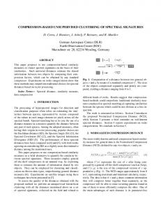
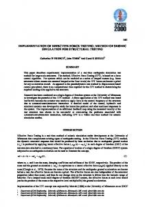
Tests on Impacted Specimen The static resistance of composite structures is, of course, a useful parameter for determining ultimate loads and margins, but present-day dimensioning also has to take into account the fact that these structures can be damaged by impacts. Indeed, even low-speed, low-energy impacts resulting, for example, from a falling tool can cause residual strength to decrease by over 50%.23 With this in mind, Eurocopter provided four specimens that had been impacted manually with a steel spherical ball. The energy was not specified, but the impact caused perforation damages and C-Scan analysis showed delamination to be absent beyond the visible damaged zone. Generally speaking, when the impacted structures were tested on standard compression machines, the damage was first seen to spread and the specimen then failed suddenly. The compression tests revealed an unusual behavior. Indeed, as can be seen in the failure pattern shown in Fig. 21, a crack of limited length is present on either side of the impact. Figure 22 gives the strains measured by the gages numbered in Fig. 21, according to the normalized value of the load. However, some of the values given by the gages affected by the crack were not taken into account as they were incoherent (i.e., 20,000 µstrain). The following interpretation of the evolution of the measured strain is proposed. 470 • Vol. 44, No. 5, October 2004
Fig. 22—Readings from 0◦ gages, compression test of impacted plate
=> Load is increased normally. Note excellent symmetry of the strains: gages 2 and 3, 4 and 9, 5 and 6. => Crack starts to grow out of the impacted zone (load 12 kN) along an orthogonal line at compression direction. From this stage onwards, the structure is no longer intact. The crack causes a change in stiffness and a redistribution of the load flow which affects input gages 1, 2, 3, and gage 10. => Load increase is continued and the crack grows progressively. Gages 4 and 9 are affected and no longer give coherent readings. The growth of the crack causes loads to pass onto the specimen sides at gages 1 and 10. At gages 2 and 3, decrease is slighter and only becomes significant when the peripheral zone, which has an extra ply, is in turn affected by the crack (gages 5 and 6). => The test is stopped. © 2004 Society for Experimental Mechanics
No loading
4650 N
8600 N
0° : compression direction
C ra ck
9450 N
12100 N
FISSURATION
Fig. 24—Failure pattern in shear of an impacted specimen
Fig. 23—Stages of the damaged area in compression after impact by the moiré shadow method
It is remarkable to observe such “growth” of a crack, as an explosive failure usually occurs as soon as a crack appears. The phenomenon observed may be due to working in imposed displacement as well as the various reinforcements present in asymmetric sandwich structures, e.g., the structural redundancy of the test rig. Before the crack appears, strain of –3873 and –2613 µ strains were obtained by calculating the average of the values given by gages 1, 2, and 3, representing a drop in resistance of about 75%. As shown in Fig. 23, a qualitative analysis of the deformed shape (due to the bad quality of the grid used) using the shadow moiré method was carried out during the second test. The evolution of the pattern of the impact provides information on the failure scenario under compression after impact, which seems to be the appearance of a progressively deeper elliptical damaged zone caused by extension of the local crushing of the honeycomb core, followed by the start of the crack at the apex of the ellipse, probably initiated by local static overstresses. The two remaining specimens were tested in shear and under combined loads. Photographs of the failures are shown in Figs. 24 and 25. In the shear test, failure was sudden, along a 45◦ line approximately and strains at the hole edges reached about 12,000 µ strains. In impacted shear, the response of the structure thus appears analog to a failure by concentration of stresses around a hole. In fact, the strain values obtained would appear to confirm the absence of delamination caused by the impact. Under combined loads, a phenomenon occurred which was analog to that observed in compression.1 First, the specimen was compression loaded. Rosettes situated in the same places as gages 1–2–3, shown in Fig. 21, supplied an average strain of –3644 µ strain at 0◦ . At this stage, the structure is intact with no cracks outside the impacted area. It was then shear-loaded and a crack very soon appeared. Just before final failure, these rosettes indicated a main direction near to 45◦ . This shows that the crack completely unloaded the zone in compression and that the stress flow was redirected to the peripheral zones of the specimen and to the test rig itself. The gages positioned close to the impact came unstuck during growth of the crack, making quantitative interpretation of the test difficult. The test rig has thus proved suitable for impacted specimen tests and enabled an original progressive crack phenomenon © 2004 Society for Experimental Mechanics
Fig. 25—Failure pattern under combined load of an impacted specimen
to be closely observed. Little is known about how stratified structures crack and this method of experimenting, which can enable propagation in “small leaps”, could be used to validate an initiation test. Moreover, from a practical point of view, the non-explosive crack growth attributable to the structural redundancy of the box gives aeronautical structure designers safety margins not shown by standard tests. Conclusions A test rig was developed to test asymmetric sandwich specimens under combined compression/shear loads. It conforms to the second level of the test pyramid. A box structure was chosen and tests simulated as realistically as possible the conditions in aeronautical structures, particularly junctions and boundary conditions. The test rig proved capable of carrying out static failure tests on specimens with carbon laminate skins. The tests effectuated showed asymmetric structures to be exceptionally strong in compression, since no global buckling was observed and failure strains are similar to those measured on single-material specimens, being more than –10,000 µ strains at failure. The shear and combined load tests produce results which are analog for breaking patterns and failure strains. Experimental Mechanics • 471
Further tests were carried out on impacted specimens and revealed progressive crack growth from the impact damage point. As far as we know, no such progressive crack growth was reported in the literature, and could be attributed to the structural redundancy of the test rig. The values observed when the crack started (about –3500 µ strains) are, however, close to standard test compression values. Note that it also demonstrates the local nature of the phenomenon. This progressive failure mode leads to the conclusion that the extrapolation of classical test results to real structures is conservative, since the existence of structural redundancy enables loads to be taken by non-damaged zones. This test rig should also be used to study crack growth in laminates under compression after impact. As is the case for the other existing test rigs of this type, the difficulty lies in estimating the stress flows directly entering the specimen. In the case of asymmetric sandwich structures, their very specific geometrically nonlinear behavior turns the stabilizing skin into an actual sensor of the loading state of the sandwich.2 It is therefore possible to measure incoming stress flow in situ on the working skin and to correlate the test on the stabilizing skin alone. Nevertheless, when the test rig uses small specimens, Saint-Venant effects play an important part in the stabilizing skin and perturb the strain field. Obviously, a future version needs to hold specimens almost twice as large (approximately 600 × 500 mm) Generally speaking, this type of test is more complex than standard tests but it does highlight mechanical phenomena that are much closer to real-life structures. Less conservative conclusions can thus be extrapolated. As in the case of composite structures, the effects of scale are evident, and the aeronautical industry greatly needs this type of test to be developed. References 1. Castanié, B., “Contribution à L’étude des Structures Sandwichs Dissymétriques,” Thesis of Supaéro (2000). See http://www.supaero.fr/disque2/ 001130.pdf. 2. Castanié, B., Barrau, J.-J., and Jaouen, J.-P., “Theoretical and Experimental Analysis of Asymmetric Sandwich Structures,” Composite Structures, 55, 295–306 (2002). 3. Noor Ahmed, K., Burton Scott, W., and Bert, C.W., “Computational Models for Sandwich Panels and Shells,” Applied Mechanics Review, 9, 155–199 (1996). 4. Satapathy, N.R. and Vinson, J.R., “Sandwich Beams with Mid-plane Asymmetry Subjected to Lateral Loads,” Journal of Sandwich Structures and Materials, 2, 379–390 (2000).
472 • Vol. 44, No. 5, October 2004
5. Daniel, I.M., “Experimental Modeling of Composites Materials,” EXPERIMENTAL MECHANICS, 39, 1–19 (1999). 6. Rouchon, J., “Certification of Large Airplane Composite Structures, Recent Progress and New Trends in Compliance Philosophy,” ICAS 1990, Vol. 2, pp. 1439–1447. 7. Niu, M.C.Y., Composite Airframe Structures, Hong-Kong Conmilit Press, Hong Kong (1992). 8. Zagainov, G.I. and Lozino-lozinsky, G.E., Composite Materials in Aerospace Design, Chapman and Hall, London. 9. Zenkert, D., The Handbook of Sandwich Construction, EMAS Publishing (1997). 10. Hoff, N.J. and Mautner, S.E., “The Buckling of Sandwich-type Panels,” Journal of the Aeronautical Science, 12 (1945). 11. Minguet, P., Dugundji, J., and Lagace, P.A., “Postbuckling Behavior of Laminated Plates Using a Direct Energy-minimization Technique,” AIAA Journal, 27 (12), (1989). 12. Kuenzi, E.W., “Stability of a Few Curved Panels Subjected to Shear,” Forest Products Laboratory, Report 1571 (1947). 13. Farlay, G.L. and Baker, D.J., “In-plane Shear Test of Thin Panels,” EXPERIMENTAL MECHANICS, 23, 81–88 (1983). 14. Llorente, S. and Weems, D., “Evaluation of a Simplified Approach to In-plane Testing for Damage Tolerance Evaluation,” Proceedings of the 46th Annual Forum of the American Helicopter Society, Vol. 1, pp. 713–720 (1990). 15. Wolf, K. and Kossira, H., “An Efficient Test Method for the Experimental Investigation of the Post-buckling Behavior of Curved Shear Panels,” ECCM Composite Testing and Standardization, Amsterdam, September (1992). 16. Romeo, G. and Frulla, G., “Buckling and Post-buckling Behavior of Anisotropic Plates Under Combined Biaxial Compression and Shear Loads,” ECCM Composite Testing and Standardization, Amsterdam, September (1992). 17. Peters, R.W., “Buckling Tests of Flat Rectangular Plates Under Combined Shear and Longitudinal Compression,” NACA Technical Note 1750 (1948). 18. Klein, H., “General About Buckling Tests With Thin-walled Shells,” Rapport DLR- Mitt, 89–13. 19. Rouse, M., Young, R.D., and Gehrki, R.E., “Structural Stability of a Stiffened Aluminum Fuselage Panel Subjected to Combined Mechanical and Internal Pressure Loads,” AIAA 2003-1423, 44th AIAA/ASME/ASCE/AHS/ASC Structures, Structural Dynamics, and Materials Conference, Norfolk, VA, April 7–10 (2003). 20. Hayman, B., Wiese, M., Davies, D., Choquese, D., Hoyning, B., and Mitush, P., “Foam-cored Sandwich Panels Under Pressure Loading: Some New Tests and Analyses,” Proceedings of the 4th International Conference on Sandwich Construction, Stockholm, Sweden, (1998). 21. Roberts, J.C., Boyle, M.P., Wienhold, P.D., and White, G.J., “Buckling, Collapse and Failure Analysis of FRP Sandwich Panels,” Composite, Part B, 33, 315–324 (2002). 22. US Military Handbook 23A, Design of Structural Sandwich Composites (1968). 23. Abrate, S., “Localized Impact on Sandwich Structure with Laminated Facings,” Applied Mechanics Review, 50 (2), 69 –82 (1997).
© 2004 Society for Experimental Mechanics