FERMILAB-CONF-09-348-CD
Computation of electron cloud diagnostics and mitigation in the Main Injector S. A. Veitzer1 , P. LeBrun2 , J. R. Cary1 , P. Spentzouris2 , Peter H. Stoltz1 and J. F. Amundson2 1 2
Tech-X Corporation, 5621 Arapahoe Ave., Suite A, Boulder, CO, 80303 Fermi National Accelerator Laboratory, P.O. Box 500, Batavia, IL 60510-5011
E-mail:
[email protected] Abstract. High-performance computations on Blue Gene/P at Argonne’s Leadership Computing Facility have been used to determine phase shifts induced in injected RF diagnostics as a function of electron cloud density in the Main Injector. Inversion of the relationship between electron cloud parameters and induced phase shifts allows us to predict electron cloud density and evolution over many bunch periods. Long time-scale simulations using Blue Gene have allowed us to measure cloud evolution patterns under the influence of beam propagation with realistic physical parameterizations, such as elliptical beam pipe geometry, selfconsistent electromagnetic fields, space charge, secondary electron emission, and the application of arbitrary external magnetic fields. Simultaneously, we are able to simulate the use of injected microwave diagnostic signals to measure electron cloud density, and the effectiveness of various mitigation techniques such as surface coating and the application of confining magnetic fields. These simulations provide a baseline for both RF electron cloud diagnostic design and accelerator fabrication in order to measure electron clouds and mitigate the adverse effects of such clouds on beam propagation.
1. Introduction Future experiments to study high energy physics require the construction of new, high-intensity particle accelerators that are pushing the frontiers of accelerator design. Electron cloud effects are considered to be one of the most important factors that will limit machine performance for high-intensity accelerators, and electron cloud mitigation methods can have a large influence on the cost and design of such accelerators. Recently, researchers have developed a new diagnostic technique that uses microwaves to measure electron cloud densities [1, 2, 3], and there are a number of experimental programs both in the United States (Fermilab, SLAC, LBL, Cornell) and abroad (CERN) that are using injected microwaves to measure both electron cloud densities and the effects of cloud mitigation techniques, such as coatings to reduce production of secondary electrons. At Fermilab, a planned upgrade of the Main Injector to 2 MW of beam power represents an important direction for the lab for producing new science. The performancedegrading aspects of electron clouds are a major concern for the Main Injector upgrade. We have recently been developing the simulation tools needed to model microwave diagnostics of electron clouds and to simulate electron cloud buildup in the Main Injector. The simulations contain detailed multi-physics processes, including RF microwave propagation through a plasma in an elliptical beam pipe, modeling of electron cloud evolution, beam currents, static external
fields, RF fields, space charge, and secondary electron emission. To achieve this, we use the plasma simulation package VORPAL [4]. The flexibility and parallel capabilities of VORPAL form a firm foundation for producing accurate and detailed results for this complex modeling challenge. We are currently performing detailed numerical simulations at the Blue Gene/P computational cluster located at the Argonne Leadership Computing Facility, as well as other high-performance clusters. We have verified the physical simulation components of VORPAL relevant to modeling electron clouds, and have validated integrated electron cloud simulations against experiments measuring cyclotron resonances and solenoidal fields [5]. We show preliminary results of these ongoing numerical studies as it relates to the proposed upgrade of the Main Injector at FermiLab. The work reported here is the result of a partnership between Tech-X Corporation and FermiLab through the COMPASS SciDAC project, in addition to funding provided by the Department of Energy through the Small Business Innovation Research (SBIR) program. The buildup of electron clouds in high-intensity accelerators can negatively impact both beam quality and overall machine performance. Electrons can gain energy due to the potential of the beam, and they can interact with the beam pipe walls and produce more electrons through secondary emission. If enough electrons build up, they can cause an increase in beam emittance and possibly excite instabilities in the beam that will limit the current and luminosity. Zimmermann presents a comprehensive review of instabilities that are driven by electron clouds in reference [6]. Recently a new diagnostic has been developed whereby microwaves are injected into accelerator beam pipe sections during normal operation. It is well-known that a plasma will induce a phase shift, and to first order, the magnitude of the phase shift is linearly dependent on the plasma electron density. The amplitude of the We track the amplitude of the RF electric field a point at the end of the vacuum chamber in the simulation; first without any electrons, and subsequently with an electron cloud. We simplify the problem by assuming that there is no change in the wave amplitude, A, or wave frequency, ω, induced by the electron cloud. The phase difference is then derived by subtracting two waveforms,
A sin(ωt + φ1 ) − A sin(ωt + φ2 ) = 2A sin[(φ1 − φ2 )/2] cos[ωt + (φ1 + φ2 )/2] ≈ A(φ1 − φ2 ) cos[ωt(φ1 + φ2 )/2]
(1) (2)
where ω is the angular frequency of the wave, φ1 and φ2 are the phase shifts of the wave for the two cases. The approximation is valid for small phase shifts. Squaring and taking a time-average over many wave periods gives the phase shift directly, D E 1 (φ1 − φ2 )2 ≈ (sin(ωt + φ1 ) − sin(ωt + φ2 ))2 (3) 2 This method works well for simulations, where electrons can be turned on and off. Experimentally, the phase shift must be deduced from other measurements, such as measuring sidebands produced by phase modulation due to gaps in the proton bunch trains. In the context of simulating electron cloud effects in the Main Injector, we use an elliptical beam pipe with major radius 5.8801 cm, and minor radius 2.3876 cm, and a length of 1.0 m. The electron cloud is initially uniformly distributed throughout the volume of the beam pipe over a length of 0.5 m with no thermal energy. The simulations reported here have a total time of 1µs, with a time step of about 2.7 ps. The frequency of the RF diagnostic wave is approximately 1.672 GHz, which is about 10% above the cutoff frequency of the beam pipe. We have also considered circular cross section beam pipes, additional electron cloud and magnetic field configurations, and the effects of higher order RF modes, with similar results.
2. Results 2.1. Beam current effects An increase in the beam current can have significant effects on the long-term electron cloud evolution and spatial distribution of the electrons. Electrons are accelerated to the center of the beam pipe when the beam passes through the cloud, and they drift to the pipe walls inbetween bunches. A higher beam current has the potential to create more secondary electrons. However, depending on the bunch spacing, the beam potential may keep the electrons from drifting all the way to the walls, thereby reducing the overall cloud density. In our particular simulations shown here, a 5-fold increase in the beam current corresponds to a significant decrease in the overall density of electrons after many bunch crossings. This is partially due to the elliptical geometry of the simulations because in the long direction, the electrons will not have enough time between bunches to drift to the walls and create more electrons through secondary emission. Recent simulations in field-free regions of the Main Injector and circular cross sections at similar bucket frequencies have shown that 1 × 10¹¹ protons/bunch creates a maximal cloud buildup [7]. Figure (1) shows a sample electron cloud density at approximately 0.485 µs after the initiation of the simulation. The top plot shows the case where there are 1 × 10¹⁰ protons per bunch, and for comparison, the bottom plot shows the case where there are 5 × 10¹⁰ protons per bunch. In the figures, a beam bunch can be seen entering the simulation region from the left moving towards the cloud. More than 25 bunches have passed through the cloud by this point in the simulation.
Figure 1. Sample electron cloud distribution at 0.484 µs in a Main Injector simulation with 1 × 10¹⁰ protons per bunch (top) and 5 × 10¹⁰ protons per bunch (bottom). The elliptical beam pipe is clipped to reveal a beam bunch entering the simulation domain to the left of the electron cloud. Electrons are colored by their along-beam velocity.
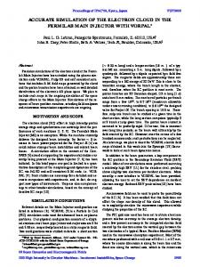
2.2. Phase shift measurements We have measured phase shifts for a variety of different simulation parameters. In the current context, we compare phase shifts for TE11 modes injected into an elliptical beam pipe to simulate electron cloud evolution in the Main Injector, as described in the section above. In the first case, with 1 × 10¹⁰ protons per bunch, the average electron density over the entire simulation is about
4.75 × 10¹¹ electrons/m3 , while in the second case, the average density is only 1.575 × 10¹¹ electrons/m3 . The computed phase shift is 3.128 × 10⁻³ rad/m in the first case and 5.823 × 10⁻⁵ in the second case. It is observed that the overall phase shift is not an accurate measure of the average density in these simulations. We believe that this is due to non-uniformity in the spatial distribution of the electron clouds. The phase shift is induced in regions where the transverse electric field of the RF signal is large. In this case, for a TE11 mode, the transverse electric field is large near the center of the beam pipe. This produces a relatively larger phase shift in the first case because there is a relatively larger concentration of electrons near the center of the beampipe. Figure (2) shows computed phase shifts as a function of time where we have used a moving window with width 0.012µs, corresponding to 20 RF periods. While the overall phase shift is an indicator of the average cloud denisty in the region where the transverse electric field is large, time-resolved measures of the phase shift such as can be seen in Figure (2) are much better for understanding the buildup and evolution of electron clouds. The large deviations in phase shift shown in the left-hand plot in Figure (2) are due to the formation of vertical bands of electrons in the cavity, which have been seen in a number of simulations, especially in the context of applied external magnetic fields. When electrons in these bands are near the center of the beam pipe, the measured phase shift is quite large, and correspondingly, the electrons have a much higher potential for disrupting the beam because they are in the path of the beam at these times. Our simulations indicate the disruption is likely to be more pronounced at the tail than the head of the beam, at least in the regime where space charge from the cloud itself is not so large as to keep a significant density of electrons in the center of the beam pipe between bunch crossings.
Figure 2. Computed phase shifts for a moving window of 0.012µs with a beam containing 1.0 × 10¹⁰ protons per bunch (left), and 5.0 × 10¹⁰ protons per bunch (right). The dramatic increase in phase shift starting at about 0.35µs in the left-hand plot is due to the emergence of non-uniform structure in the clouds. The overall number of electrons decreases only about 14% in the first case, but by nearly 30% in the second case.
2.3. Magnetic field effects External magnetic fields can also have a significant effect on the buildup and evolution of electron clouds in accelerators. One potential technique for mitigating electron cloud buildup is to apply a solenoidal field which confines secondary electrons near the beam pipe walls. This serves two purposes; (1) electrons are confined in a region where they will not disrupt the beam, and (2) electrons do not gain enough energy from the beam potential to effectively increase the cloud density through multipacting and secondary electron emission. We have performed simulations with the Main Injector geometry including the effects of externally applied fields. Figure (3)
shows results for two different magnetic field configurations at simulation times of 17 ns (left), 0.5µs (middle), and 1.0µs (right). The magnetic fields are uniform in space. The first bunch crossing occurs around 17 ns. Our simulations indicate that while modest solenoidal fields are effective in confining electrons near the walls, and thereby mitigating the effects of electron clouds, even a small transverse dipole field negates this effect, as can be seen in the figures. We conclude that using solenoidal fields to mitigate electron cloud buildup might be an effective technique in field-free regions. However, care needs to be exercised in dipole and quadrupole regions.
Figure 3. Transverse profile of electron cloud at three different simulation times. The top row is for the case where there is an applied 10 Gauss solenoidal external magnetic field, while the bottom row there is a 10 Gauss solenoidal field and an additional 10 Gauss dipole (transverse) field applied.
Acknowledgments Much of this work was performed under the auspices of the Department of Energy under Small Business Innovation Research Contract DE-FG02-08ER85042. The authors would like to acknowledge the hard work of the VORPAL development team: T. Austin, G. I. Bell, D. L. Bruhwiler, R. S. Busby, J. Carlsson, M. Carey, B. M. Cowan, D. A. Dimitrov, A. Hakim, J. Loverich, S. Mahalingam, P. Messmer, P. J. Mullowney, C. Nieter, K. Paul, C. Roark, S. W. Sides, N. D. Sizemore, D. N. Smithe, D. J. Wade-Stein, G. R. Werner, M. Wrobel, N. Xiang, C. D. Zhou. References [1] [2] [3] [4] [5] [6] [7]
Kroyer T 2005 CERN-THESIS-2005-061, Vienna Tech. U. Kroyer T, Caspers F, Mahner E and Wien T 2005 Proc. of PAC05 Byrd J, De Santis S, Sonnad K and M. Pivi 2007 Proc. of PAC07 Nieter C, Cary J R 2004 J. Comput. Phys., 196, pp. 448-73 Veitzer S A, Sonnad K, Stoltz P H and Byrd A 2009 Proc. of PAC09 Zimmermann F 2004 Phys. Rev. ST Accel. Beams 7, 124801, DOI: 10.1103/PhysRevSTAB.7.124801 Furman M A, Kourbanis I and Zwaska R M 2009 Proc. of PAC09