Hindawi Publishing Corporation Mathematical Problems in Engineering Volume 2015, Article ID 568176, 9 pages http://dx.doi.org/10.1155/2015/568176
Research Article Computation of Flow Past an In-Line Oscillating Circular Cylinder and a Stationary Cylinder in Tandem Using a CIP-Based Model Yingnan Fu,1 Xizeng Zhao,1,2 Xinggang Wang,2 and Feifeng Cao3 1
Ocean College, Zhejiang University, Hangzhou 310058, China State Key Laboratory of Hydrology-Water Resources and Hydraulic Engineering, Nanjing Hydraulic Research Institute, Nanjing 210029, China 3 Institute of Harbor-Channel and Coastal Engineering, Department of Civil Engineering, Zhejiang University of Technology, Hangzhou 310014, China 2
Correspondence should be addressed to Xizeng Zhao;
[email protected] Received 13 April 2015; Revised 21 May 2015; Accepted 27 May 2015 Academic Editor: Ming Zhao Copyright © 2015 Yingnan Fu et al. This is an open access article distributed under the Creative Commons Attribution License, which permits unrestricted use, distribution, and reproduction in any medium, provided the original work is properly cited. Viscous flow past an upstream in-line forced oscillating circular cylinder with a stationary cylinder downstream at Reynolds number of 100 is investigated using a CIP model. The model is established in a Cartesian coordinate system using a high-order difference method to discretise the Navier-Stokes equations. The fluid-structure interaction is treated as a multiphase flow with fluid and solid phases solved simultaneously. An immersed boundary method is used to deal with the fluid-body coupling. The CFD model is firstly applied to the computation of flow past a fixed circular cylinder for its validation; then flow over two stationary tandem cylinders is investigated and good agreements are obtained comparing with existing ones. Computations are then performed with flow past two tandem cylinders with an upstream in-line oscillating cylinder with a small spacing 𝐿 = 2𝐷. Considerable attention is paid to the spectrum characteristics and vortex modes.
1. Introduction Flow over multiple bluff bodies is one of the classical issues in fluid mechanics. It is of great importance in engineering applications, such as heat exchangers, adjacent tall buildings, and piles of offshore platforms. The interaction between the multiple bodies and the wake is much more complicated than that of flow past a single body. The tandem arrangement is one of the simplest configurations of the multiple bluff bodies. Extensive experimental and numerical studies have been reported about flow past two stationary tandem circular cylinders. Zdravkovich (1977) [1] revealed a discontinuous “jump” at some critical spacing in his measurements and found the discontinuity is caused by the abrupt change from one stable flow pattern to another at the critical spacing. Li et al. (1991) [2] utilized a finite element program to simulate flow past two tandem circular cylinders at different intervals for 𝑅𝑒 = 100. Discontinuity changes
in the flow pattern, the Strouhal number, and the pressure distribution were detected. Mittal et al. (1997) [3] used a finite element formation to simulate three configurations at 𝑅𝑒 = 100 and 1000. It was observed that the flow characteristics depend strongly on the arrangements of the cylinders and the Reynolds number. Meneghini et al. (2001) [4] presented the results of flow around tandem circular cylinders for Reynolds number of 200. Vorticity contours and force tine histories were displayed. Jester and Kallinderis (2003) [5] employed a second-order upwind scheme to investigate this problem. Qualitative and quantitative comparisons were made with published experimental data. The mean and fluctuating lift and drag coefficients were recorded for center-to-center cylinder spacings between 2 and 10 diameters in Sharman et al. (2005) [6]. Results showed that the critical spacing was between 3.75 and 4 diameters. Mussa et al. (2009) [7] applied the LBE (Lattice Boltzmann Equation) method with MRT (multiple relaxation time) to simulate the flow past
2 two tandem cylinders in an unbounded domain with 𝑅𝑒 = 100 and got perfect results. Numerical studies of Liu et al. (2013) [8] showed that separated point of the shear layer backwards when 𝐿/𝐷 increases because of the interference of downstream cylinder. The study concerning oscillating circular cylinders in tandem arrangement is relatively rare. Direct numerical simulation was carried out by Li et al. (1992) [9] to study the response of a transversely oscillating cylinder in uniform flow and in the wake of an upstream cylinder. They found that the response of the cylinder wake was either a periodic (lock-in) or a quasi-periodic (nonlock-in) state. Mahir and Rockwell (1996) [10] investigated the wakes between and downstream of a tandem arrangement of two transversely oscillating cylinders with a phase difference experimentally. Their results showed that the lock-in range is much wider than that of a corresponding single cylinder. Following the experiment of Mahir and Rockwell (1996) [10], Papaioannou et al. (2006) [11] conducted a numerical study to investigate the holes in the Arnold tongues. Zou et al. (2004) [12] simulated the flow past a forced system of a stationary circular cylinder and a forced transversely oscillating cylinder downstream. The vortex switch and the change of vortex modes were observed in the “lock-in” region. Prasanth and Mittal (2009) [13] investigated the flow-induced oscillation of two circular cylinders in tandem arrangement at low Reynolds number numerically. The phase between the transverse responses of the two cylinders was studied. Nonlinear responses to a transversely oscillating cylinder in the wake of a stationary upstream cylinder were studied by Yang and Zheng (2010) [14], based on velocity phase portraits. They categorized the nonlinear response states into three states: lock-in, transitional, and quasi-periodic. Huera-Huarte and Bearman (2011) [15] carried out an experiment to investigate vortex and wakeinduced vibrations of two tandem flexible circular cylinders. Different response regimes have been identified based on the type of oscillations exhibited by the cylinders: vortexinduced (VIV), wake-induced (WIV), or combinations of both. Bao et al. (2012) [16] employed LBM (Lattice Boltzmann Method) to study flow around a transversely oscillating cylinder in tandem with a stationary cylinder downstream. The influences of spacing, oscillation frequency, and amplitude were investigated. Tao et al. (2013) [17] utilized LBM to study flow past a pair of rotating circular cylinders in tandem arrangement at 𝑅𝑒 = 100. Flow past two cylinders in tandem arrangement under forced vibration has been studied experimentally by Yang et al. (2014) [18] employing the hydrogen bubble visualization technique at 𝑅𝑒 = 250. One of the greatest challenges in the simulation of flow around oscillating cylinders is to deal with moving solid boundaries in complex geometries, especially for large amplitude body motions. The ALE (Arbitrary Lagrangian-Eulerian) method has been used in some studies. This means that the domain should be remeshed at every time interval; it is time-consuming. Hence, a numerical method should be proposed without aforementioned restrictions. In this paper, an Immersed Boundary Method [19] is adopted to treat the movable structure boundaries. Meanwhile, the fluidstructure interaction is treated as a multiphase problem.
Mathematical Problems in Engineering To do so, the CIP/CCUP (constraint interpolation profile/CIP combined, unified procedure) [20] is combined with the Cartesian grid system where the multiphase problem is solved in one set of equations. The CIP method has been applied for water-body interaction problems of free surface flow [21, 22]. In the present study, the CIP method is used for the study of flow over a streamwise oscillating circular cylinder with a stationary cylinder downstream. To date, few studies considering the flow past two tandem circular cylinders with the upstream one forced to oscillate streamwise to the flow could be found. The objective of the present study is to extend the CIP-based method for this gap. In this paper, the Reynolds number remains at 100, oscillating amplitude is 𝐴/𝐷 = 0.3, and the spacing between two tandem cylinders is 𝐿/𝐷 = 2.0. By changing the oscillating frequency (𝑓𝑒 ) of the upstream cylinder (𝑓𝑒 /𝑓0 = 0.5–1.7; 𝑓0 is the natural shedding frequency of the two stationary tandem cylinders), the response of the wake is investigated. The rest of the paper is organized as follows. Section 2 gives the CIPbased numerical model. The flow solver and the coupling of fluid-body are briefly introduced. In Section 3, the current numerical model is first applied to flow over a fixed circular cylinder and two stationary tandem circular cylinders. Then, flow past an oscillating circular cylinder with a stationary cylinder downstream is computed in Section 4. Summary and conclusions are given in the final section.
2. Mathematical Modeling 2.1. Governing Equations. The basic equations governing the incompressible fluid flow are the mass conservation equation and the Navier-Stokes momentum equations written as 𝜕𝑢𝑖 = 0, 𝜕𝑥𝑖 𝜕𝑢𝑖 𝜕𝑢 1 𝜕𝑝 1 𝜕𝑆𝑖𝑗 + + 𝑓𝑖 , + 𝑢𝑗 𝑖 = − 𝜕𝑡 𝜕𝑥𝑗 𝜌 𝜕𝑥𝑖 𝜌 𝜕𝑥𝑗
(1)
where Cartesian tensor notation is used (𝑖 = 1, 2) and 𝑡, 𝑢𝑗 , 𝑝, and 𝑥𝑗 are the time, velocities, hydrodynamic pressure, and spatial coordinates, respectively. 𝑓𝑖 represents momentum forcing components. 𝑆𝑖𝑗 is the viscous term given by 𝑆𝑖𝑗 = 𝜇 (
𝜕𝑢𝑖 𝜕𝑢𝑗 + ), 𝜕𝑥𝑗 𝜕𝑥𝑖
(2)
where 𝜌 and 𝜏 are the density and viscosity, respectively, appropriate for the phase that is occupying the particular spatial location at a given instant. The numerical model considers the fluid-body interaction as a multiphase problem that includes fluid and structure. A fixed Cartesian grid that covers the whole computation domain is used. A volume function (or color function) 𝜙𝑚 (𝑚 = 1 and 2 indicate fluid and solid, resp.) is defined to represent and track the interface. The total volume function
Mathematical Problems in Engineering
3
Table 1: Comparison of mean drag coefficient (𝐶𝑑 ) and Strouhal number (𝑆𝑡 ) with those of other authors. Data Mesh 1 Mesh 2 Mesh 3 Exp. (1959) [28] Exp. (1988) [29] Herfjord (1996) [30] Calhoun (2002) [31] Linnick and Fasel (2005) [32] Berthelsen and Faltinsen (2008) [33] Rajani et al. (2009) [34]
Min size of mesh 0.01D 0.02D 0.04D
𝐶𝑑 1.38 1.34 1.28 1.26 1.36 1.33 1.34 1.38 1.34
for fluid and body is solved by using the following advection equation: 𝜕𝜙12 𝜕𝜙 + 𝑢𝑖 12 = 0. 𝜕𝑡 𝜕𝑥𝑖
(3)
Here, 𝜙12 = 𝜙1 + 𝜙2 . The density and viscosity of the solid phase are assumed to be the same as those of a liquid phase to ensure stability. The volume function for solid body 𝜙2 is determined by a Lagrangian method in which a rigid body is assumed. The volume function for fluid 𝜙1 is then determined by 𝜙1 = 1.0 − 𝜙2 . After all volume functions have been calculated, the physical property 𝜆, such as the density and viscosity, is calculated by the following formula: 2
𝜆 = ∑ 𝜙𝑚 𝜆 𝑚 .
(4)
𝑚=1
2.2. Numerical Methods. Following Zhao and Hu (2012) [23], the governing equations are discretized using a high-order finite difference method on a Cartesian grid system. A staggered grid configuration is used to discretize the dependent variables. The governing equations (1) are solved using a fractional step scheme: 𝜕𝑢 𝜕𝑢𝑖 + 𝑢𝑗 𝑖 = 0, 𝜕𝑡 𝜕𝑥𝑗 𝜕𝑢𝑖∗∗ − 𝜕𝑢𝑖∗ 2𝜇 𝜕𝑆𝑖𝑗 + 𝑓𝑖 , = Δ𝑡 𝜌 𝜕𝑥𝑗 ∗∗ 𝜕 1 𝜕𝑝 1 𝜕𝑢𝑖 ( )= , 𝜕𝑥𝑖 𝜌 𝜕𝑥𝑖 Δ𝑡 𝜕𝑥𝑖
𝑢𝑖𝑛+1 = 𝑢𝑖∗∗ −
Number of meshes 307800 92800 32175
(5)
Δ𝑡 𝜕𝑝 . 𝜌 𝜕𝑥𝑖
In the advection phase the spatial derivatives of the velocities are needed to apply the CIP method [20] for this phase. In the first nonadvection phase, terms of diffusion and external forces are solved by explicit method and renewed intermediate velocities are obtained. In the final phase, the velocities are updated coupling with pressure field.
𝑆𝑡 0.166 0.166 0.166 0.164 0.168 0.175 0.166 0.169 0.157
To model the body motions, the fluid-structure interaction is coupled by using the Fractional Area Volume Obstacle Representation (FAVOR) method. The FAVOR was shown to be one of the most efficient methods to treat the immersed solid bodies. The effect of a moving solid body on the flow is considered by imposing the velocity field of the solid body into the flow at the solid edge. The following equation is introduced to update the local information of the fluid domain covered by the body: 𝑈 = 𝜙2 𝑈𝑏 + (1 − 𝜙2 ) 𝑢.
(6)
Here, 𝑈𝑏 is the local velocity of the solid body and 𝑢 denotes the flow velocity obtained from the fluid flow solver. The solid phase 𝜙2 is obtained using a virtual particle method [21]. 𝑈𝑏 , the local velocity of the solid body, is tracked by a Lagrange method. By integrating the pressure on the body surface, the hydrodynamic forces acting on the body are first calculated. With Newton’s Law, the body motion accelerations and velocities are calculated. More details can be found in previous references [21, 24].
3. Numerical Results 3.1. Flow Past a Stationary Circular Cylinder. Convergence study has first been performed for flow past a stationary circular cylinder at low Reynolds number (𝑅𝑒 = 100) as a reference for further investigation. The Reynolds number was defined on the diameter 𝐷 of the circular cylinder and the dynamic viscosity coefficient 𝜇. Three different nonuniform meshes are used with a minimum grid size of Δ𝑥 = Δ𝑦 = 0.01𝐷, 0.02𝐷, and 0.04𝐷, respectively. Results of the mean value of drag coefficient (𝐶𝑑 ) and the Strouhal number (𝑆𝑡 ) are shown in Table 1 and compared with previous experimental and numerical results. It can be seen that the computation converges fast and the results of mesh 1 and mesh 2 show excellent agreements with both the experimental and numerical data in existing literatures. Thus mesh 2 is adopted in the following calculations. 3.2. Flow Past Two Stationary Cylinders in Tandem. Generally, the flow patterns of flow past two stationary tandem cylinders can be divided into two regimes by the critical spacing
4
Mathematical Problems in Engineering
10D U
10D L 10D
35.5D
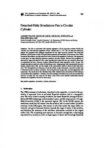
Figure 1: Sketch of the computational domain for flow past two tandem circular cylinders.
(a)
(b)
Figure 2: The computational mesh for flow past two tandem circular cylinders and local mesh near the cylinders with 𝐿/𝐷 = 5.0.
𝐿 𝑐 . When 𝐿 < 𝐿 𝑐 , there is no clear vortex shedding from the upstream cylinder (vortex suppression regime, VS). When 𝐿 > 𝐿 𝑐 , the vortex sheds from both the upstream and downstream cylinders (vortex formation regime, VF). In this section, flow past two stationary cylinders in tandem at 𝑅𝑒 = 100 is computed with different spacing ratios 𝐿/𝐷. The computational domain is scheduled in Figure 1. The inlet is located 10𝐷 upstream of the front cylinder, and the outlet is located 25.5𝐷 downstream of the front cylinder. The upper and lower boundaries are placed 10𝐷 away from the centerline of the domain. On the inlet, the streamwise velocity is set to make 𝑅𝑒 = 100 for the fixed tandem circular cylinders and the transverse velocity is zero. On the outlet, a zero gradient boundary condition is specified. A free-slip boundary condition is imposed on the lateral boundaries and no-slip condition is applied on the surface of the two cylinders. Figure 2 shows the computational mesh and the detailed view of the mesh with 𝐿/𝐷 = 5.0. Figure 3 illustrated the variation of coefficients at different spacing ratios 𝐿/𝐷, ranging from 1.5 to 7.0. The computed 𝑆𝑡 is shown in Figure 3(a), where the results of Li et al. (1991) [2],
Sharman et al. (2005) [6], and Zheng et al. (2008) [25] are also presented for comparison. It shows a good agreement with existing results except for the results of Li et al. (2008) [2] a little larger. Figure 3(b) displays the mean value of the drag coefficient 𝐶𝑑 and shows a good consistency with that of Sharman et al. (2005) [6]. A sudden jump can be observed at 𝐿/𝐷 = 3.5–4.0, which means that the critical spacing 𝐿 𝑐 is between 3.5 and 4.0. Figure 3(c) shows the same property as Figures 3(a) and 3(b). Figure 4 plots the vorticity contours at 𝐿/𝐷 = 3.5 and 4.0. Positive contours are plotted in slid lines and negative contours in dashed lines. There is no clear vortex shedding from the upstream cylinder at 𝐿/𝐷 = 3.5. After the critical spacing, the vortex shedding from both the cylinders can be observed at 𝐿/𝐷 = 4.0. 3.3. Flow Past a Streamwise Oscillating Circular Cylinder with a Stationary Cylinder Downstream in Tandem. In this section, flow past a streamwise oscillating circular cylinder with a stationary cylinder downstream in tandem with the spacing ratio 𝐿/𝐷 = 2.0 at 𝑅𝑒 = 100 is investigated. 𝐿/𝐷 = 2.0 is in the regime of VS, where the wake interaction of upstream and downstream is much more complicated than that of VF because of the close distance. The computational domain and mesh are similar to that of flow past two stationary cylinders, as shown in Figures 1 and 2. The upstream cylinder oscillates streamwise with an imposed motion 𝑋(𝑡) = 𝐴sin(2𝜋𝑓𝑒 𝑡). The oscillating amplitude 𝐴 is set to be 0.3𝐷, relatively large amplitude for vortex mode analysis [26]. The natural shedding frequency of flow past two stationary cylinders 𝑓0 is 0.122 from the results of Section 2.2. The oscillating frequency 𝑓𝑒 /𝑓0 varies from 0.5 to 1.7. In the present study, the computational time is set as 300 s and time interval is 0.002 s. The actual consuming time is no more than 83 min per condition using PC Intel i7-3770. Figure 5 plots the spectrum of lift force for both the cylinders. It can be noticed that the upstream and downstream wakes have peaks at 𝑓0 , 𝑓𝑒 , or their harmonics. The corresponding vorticity contours are presented in Figure 6. When 𝑓𝑒 /𝑓0 = 0.5, the natural shedding frequency 𝑓0 plays a dominant role in the wake of both the cylinders. The vortex shedding is familiar with that of flow past two stationary tandem cylinders as shown in Figure 6(a). As the oscillating frequency 𝑓𝑒 /𝑓0 increases to 0.7, the natural shedding frequency 𝑓0 dominates the upstream wake, while the forced frequency 𝑓𝑒 plays an important role in the downstream wake, and its harmonics becomes stronger. Corresponding vorticity contour displays a symmetric S pattern the same as flow past an oscillating cylinder [27]. The vortex shed simultaneously from both the upper and lower sides of the cylinders. At 𝑓𝑒 /𝑓0 = 0.9–1.1, the significant peaks appear at the excitation frequency, and 2𝑓𝑒 exists in a much lower energy. The formation of vortex remains the same as that of 𝑓𝑒 /𝑓0 = 0.7. There is a sudden change at 𝑓𝑒 /𝑓0 = 1.3, 0.5𝑓𝑒 emerges and plays the significant role in both the upstream and downstream wake, and its harmonics 1.5𝑓𝑒 and 2.5𝑓𝑒 also behave at 𝑓𝑒 /𝑓0 = 1.3–1.7. The vortex sheds in an irregular 2P structure at 𝑓𝑒 /𝑓0 = 1.3 and turns to a regular 2P at 𝑓𝑒 /𝑓0 = 1.5 as displayed in Figures 6(f)-6(g). Figure 7 shows
Mathematical Problems in Engineering
5
0.17
1.4
0.16
1.2 1.0
0.15
0.8
St
Cd
0.14
0.6
0.13 0.4 0.12
0.2
0.11
0.0
0.10 1
2
3
4
5
6
−0.2
7
1
2
3
4 L/D
L/D
Li et al. (1991) Single cylinder
Current results Zheng et al. (2008) Sharman et al. (2005)
Cylinder 1 (Sharman et al.) Cylinder 2 (Sharman et al.) Single cylinder
(a)
5
6
7
Cylinder 1 Cylinder 2
(b)
1.2 1.0
Cl rms
0.8 0.6 0.4 0.2 0.0 1
2
3
4 L/D
5
6
7
Cylinder 1 Cylinder 2 Single cylinder (c)
Figure 3: Variation of coefficients with spacing ratio 𝐿/𝐷 for flow past two stationary circular cylinders: (a) Strouhal number 𝑆𝑡 ; (b) mean value of the drag coefficient 𝐶𝑑 ; (c) rms value of the lift force coefficient 𝐶𝑙rms .
(a)
(b)
Figure 4: Vorticity contours of flow past two stationary tandem circular cylinders: (a) 𝐿/𝐷 = 3.5; (b) 𝐿/𝐷 = 4.0.
the vorticity contours in one period. The vorticity contours at 0𝑇 and 𝑇 are nearly identical in the near-wake region at 𝑓𝑒 /𝑓0 = 0.5 and 1.0, but it plots a good coincidence of 𝑇 and 2𝑇 at 𝑓𝑒 /𝑓0 = 1.5. It can be seen from Figures 8(c)-8(d) that a limit cycle is temporally repeated in the lift portrait plots for
both the upstream and downstream cylinder at 𝑓𝑒 /𝑓0 = 1.5, which shows a lock-in phenomenon. However, in Figures 8(a)-8(b), there are no single orbits but multiple loops, which indicate a quasi-periodic characteristic for both the upstream and downstream cylinder.
Mathematical Problems in Engineering
fe /f0 = 1.1
fe
0.25 0.50 Frequency (Hz)
fe /f0 = 1.3
0.5fe
0.005 0.000 0.00 0.100 0.075 0.5fe 0.050 0.025 0.000 0.00
0.06 0.5fe 0.04 0.02 0.00 0.00
1.5fe 0.25 0.50 Frequency (Hz)
Amplitude
0.75
fe /f0 = 1.5 1.5fe 0.25 0.50 Frequency (Hz)
0.75
fe /f0 = 1.7 1.5fe
2.5fe
0.25 0.50 Frequency (Hz) (a)
Amplitude
0.75
0.75
fe /f0 = 0.5
f0
2.0 1.0
3fe
0.0 0.00
0.25 0.50 Frequency (Hz)
×10−7 1.5 fe
1.0 0.5
fe /f0 = 0.7 2fe
0.25 0.50 Frequency (Hz)
×10−7 10.0 7.5 5.0 2.5 0.0 0.00
fe
5.0
0.75
fe /f0 = 1.0
fe 2fe
0.25 0.50 Frequency (Hz)
0.75
fe /f0 = 1.1
fe
2.5
2fe
0.0 0.00
0.25 0.50 Frequency (Hz)
0.015 0.010
0.75
fe /f0 = 0.9
0.25 0.50 Frequency (Hz)
0.75 0.0 0.00 ×10⁻⁸ 7.5
0.75
f0
0.0 0.00
1.5
0.75
0.25 0.50 Frequency (Hz)
×10−4 3.0
×10−7 2.3
Amplitude
Amplitude Amplitude Amplitude
0.75
fe /f0 = 1.0
fe
×10−8 4.50 3.00 1.50 0.00 0.00
0.010
0.25 0.50 Frequency (Hz)
Amplitude
2fe
Amplitude
0.5 0.0 0.00
0.015
fe /f0 = 0.9
fe
1.0
Amplitude
×10−7 1.5
Amplitude
×10−8 2.0 f0 fe /f0 = 0.7 1.5 1.0 2fe 3f e 0.5 fe 0.0 0.00 0.25 0.50 0.75 Frequency (Hz)
×10−7 2.3 1.5 0.75 0.0 0.00
Amplitude
Amplitude
×10−5 4.0 fe /f0 = 0.5 3.0 f0 2.0 1.0 f 3fe e 0.0 0.00 0.25 0.50 0.75 Frequency (Hz)
Amplitude
Amplitude
Amplitude
Amplitude
6
fe /f0 = 1.3
0.5fe
0.005 0.000 0.00 0.100 0.5fe 0.075 0.050 0.025 0.000 0.00 0.12 0.5fe 0.09 0.06 0.03 0.00 0.00
0.75
1.5fe 0.25 0.50 Frequency (Hz)
0.75
fe /f0 = 1.5 1.5fe 0.25 0.50 Frequency (Hz)
0.75
fe /f0 = 1.7 1.5fe 0.25 0.50 Frequency (Hz)
0.75
(b)
Figure 5: Spectrum analysis of the lift force for flow around upstream oscillating cylinder and downstream fixed cylinder: (a) upstream cylinder; (b) downstream cylinder.
Mathematical Problems in Engineering
7
(a)
(b)
(c)
(d)
(e)
(f)
(g)
(h)
Figure 6: Vortex contours of flow around upstream oscillating cylinder and downstream fixed cylinder: (a) 𝑓𝑒 /𝑓0 = 0.5; (b) 𝑓𝑒 /𝑓0 = 0.7; (c) 𝑓𝑒 /𝑓0 = 0.9; (d) 𝑓𝑒 /𝑓0 = 1.0; (e) 𝑓𝑒 /𝑓0 = 1.1; (f) 𝑓𝑒 /𝑓0 = 1.3; (g) 𝑓𝑒 /𝑓0 = 1.5; (h) 𝑓𝑒 /𝑓0 = 1.7.
0T
0T
0T
0.5T
0.5T
T
T
T
2T
(a)
(b)
(c)
Figure 7: Vortex contours in one period: (a) 𝑓𝑒 /𝑓0 = 0.5; (b) 𝑓𝑒 /𝑓0 = 1.0; (c) 𝑓𝑒 /𝑓0 = 1.5.
4. Conclusions A CIP-ZJU model is utilized to simulate the viscous flow past one and two circular cylinders in this paper. The model is established in a Cartesian coordinate system, using a CIP method as the base flow solver to discretise the N-S equations. The fluid-structure interaction is treated as a multiphase flow with fluid and solid phases solved simultaneously. An Immersed Boundary Method was used to deal with the fluidbody coupling. Flow past a stationary circular cylinder at 𝑅𝑒 = 100 is computed firstly to validate the method. Good agreements
are obtained comparing with existing literatures. Then flow around two stationary tandem circular cylinders is computed at 𝑅𝑒 = 100 of different spacing ratios 𝐿/𝐷 = 1.5–7.0. The critical spacing 𝐿 𝑐 is between 3.5 and 4.0 as the results shown, which agrees well with previous data. Benchmark test cases showed that the CIP-based numerical discretization is accurate enough for low Reynolds number flows. Flow around an upstream in-line oscillating cylinder and a stationary cylinder in tandem with spacing ratio 𝐿/𝐷 = 2.0 at 𝑅𝑒 = 100 is investigated. The oscillating amplitude is set as 0.3𝐷, and the oscillating frequency 𝑓𝑒 /𝑓0 is varied from 0.5 to 1.7. The spectrum analysis of lift force for both cylinders is
8
Mathematical Problems in Engineering fe /f0 = 0.5
0
0
−1
−1 −0.030
fe /f0 = 0.5
1
X(t)/A
X(t)/A
1
−0.015
0.000 Cl (t)
0.015
−0.070
0.030
−0.035
(a)
fe /f0 = 1.5
0.070
fe /f0 = 1.5
1
X(t)/A
X(t)/A
0.035
(b)
1
0
0
−1
−1 −1.0
0.000 Cl (t)
−0.5
0.0 Cl (t)
0.5
1.0
−1.0
−0.5
(c)
0.0 Cl (t)
0.5
1.0
(d)
Figure 8: Phase portrait plot at 𝑓𝑒 /𝑓0 = 0.5 and 1.5: (a, c) upstream cylinder; (b, d) downstream cylinder.
discussed. When 𝑓𝑒 /𝑓0 = 1.1, the natural shedding frequency 𝑓0 and the imposed frequency 𝑓𝑒 appear in the peaks. As the excitation frequency increases, 0.5𝑓𝑒 plays a dominate role in both the upstream and downstream of the tandem system and 1.5𝑓𝑒 and 2.5𝑓𝑒 appear in a very low power. At the low oscillating frequency 𝑓𝑒 /𝑓0 = 0.5, the shape of vortex is similar to that of flow past two stationary cylinders and the phase portrait of lift force shows a quasi-periodic characteristic. With the frequency increasing, S mode is observed at 𝑓𝑒 /𝑓0 = 0.7–1.2 and the vorticity contours show a good accordance of 0𝑇 and 𝑇. A sudden change of the vortex formation is displayed at 𝑓𝑒 /𝑓0 = 1.3, when vortex of irregular 2P mode shed from the cylinders. Regular 2P mode is formed at 𝑓𝑒 /𝑓0 = 1.5, and the vorticity contours show a good identity every 2𝑇. The portrait lift force displays a lockin phenomenon with a single limit cycle.
Conflict of Interests The authors declare that there is no conflict of interests regarding the publication of this paper.
Acknowledgments This work was supported by National Natural Science Foundation of China (51209184 and 51479175), Open Research Foundation of State Key Laboratory of Hydrology-Water Resources and Hydraulic Engineering (2013490211), Specialized Research Fund for the Doctoral Program of Higher Education (20120101120150), and Key Laboratory of WaterSediment Sciences and Water Disaster Prevention of Hunan Province (Grant no. 2013SS03).
References [1] M. M. Zdravkovich, “Review of flow interference between two circular cylinders in various arrangements,” Journal of Fluids Engineering, vol. 99, no. 4, pp. 618–633, 1977. [2] J. Li, A. Chambarel, M. Donneaud, and R. Martin, “Numerical study of laminar flow past one and two circular cylinders,” Computers and Fluids, vol. 19, no. 2, pp. 155–170, 1991. [3] S. Mittal, V. Kumar, and A. Raghuvanshi, “Unsteady incompressible flows past two cylinders in tandem and staggered arrangements,” International Journal for Numerical Methods in Fluids, vol. 25, no. 11, pp. 1315–1344, 1997.
Mathematical Problems in Engineering [4] J. R. Meneghini, F. Saltara, C. L. R. Siqueira, and J. A. Ferrari Jr., “Numerical simulation of flow interference between two circular cylinders in tandem and side-by-side arrangements,” Journal of Fluids and Structures, vol. 15, no. 2, pp. 327–350, 2001. [5] W. Jester and Y. Kallinderis, “Numerical study of incompressible flow about fixed cylinder pairs,” Journal of Fluids and Structures, vol. 17, no. 4, pp. 561–577, 2003. [6] B. Sharman, F. S. Lien, L. Davidson, and C. Norberg, “Numerical predictions of low Reynolds number flows over two tandem circular cylinders,” International Journal for Numerical Methods in Fluids, vol. 47, no. 5, pp. 423–447, 2005. [7] A. Mussa, P. Asinari, and L.-S. Luo, “Lattice Boltzmann simulations of 2D laminar flows past two tandem cylinders,” Journal of Computational Physics, vol. 228, no. 4, pp. 983–999, 2009. [8] J. Liu, H. Guo, and J. Zhao, “Numerical simulation of flow around two tandem circular cylinders of equal diameter,” Periodical of Ocean University of China, vol. 43, no. 12, pp. 92–97, 2013. [9] J. Li, J. Sun, and B. Roux, “Numerical study of an oscillating cylinder in uniform flow and in the wake of an upstream cylinder,” Journal of Fluid Mechanics, vol. 237, pp. 457–478, 1992. [10] N. Mahir and D. Rockwell, “Vortex formation from a forced system of two cylinders. Part I: tandem arrangement,” Journal of Fluids and Structures, vol. 10, no. 5, pp. 473–489, 1996. [11] G. V. Papaioannou, D. K. P. Yue, M. S. Triantafyllou, and G. E. Karniadakis, “Evidence of holes in the arnold tongues of flow past two oscillating cylinders,” Physical Review Letters, vol. 96, no. 1, Article ID 014501, 2006. [12] J.-F. Zou, A.-L. Ren, and J. A. Deng, “Forced system of two cylinders with various spacings,” China Ocean Engineering, vol. 18, no. 3, pp. 391–402, 2004. [13] T. K. Prasanth and S. Mittal, “Flow-induced oscillation of two circular cylinders in tandem arrangement at low Re,” Journal of Fluids and Structures, vol. 25, no. 6, pp. 1029–1048, 2009. [14] X. Yang and Z. C. Zheng, “Nonlinear spacing and frequency effects of an oscillating cylinder in the wake of a stationary cylinder,” Physics of Fluids, vol. 22, no. 4, 2010. [15] F. J. Huera-Huarte and P. W. Bearman, “Vortex and wakeinduced vibrations of a tandem arrangement of two flexible circular cylinders with near wake interference,” Journal of Fluids and Structures, vol. 27, no. 2, pp. 193–211, 2011. [16] S. Bao, S. Chen, Z. H. Liu, J. Li, H. F. Wang, and C. G. Zheng, “Simulation of the flow around an upstream transversely oscillating cylinder and a stationary cylinder in tandem,” Physics of Fluids, vol. 24, no. 2, Article ID 023603, 2012. [17] S. Tao, L. Zhou, and Z. Zong, “Multi-block lattice Boltzmann method for flows around two tandem rotating circular cylinders,” Chinese Journal of Computational Physics, vol. 30, no. 2, pp. 159–168, 2013. [18] Y. C. Yang, T. B. Aydin, and A. Ekmekci, “Flow past tandem cylinders under forced vibration,” Journal of Fluids and Structures, vol. 44, pp. 292–309, 2014. [19] C. S. Peskin, “Flow patterns around heart valves: a numerical method,” Journal of Computational Physics, vol. 10, no. 2, pp. 252–271, 1972. [20] T. Yabe, F. Xiao, and T. Utsumi, “The constrained interpolation profile method for multiphase analysis,” Journal of Computational Physics, vol. 169, no. 2, pp. 556–593, 2004. [21] C. H. Hu and M. Kashiwagi, “A CIP-based method for numerical simulations of violent free-surface flows,” Journal of Marine Science and Technology, vol. 9, no. 4, pp. 143–157, 2004.
9 [22] G. He, “A new adaptive Cartesian-grid CIP method for computation of violent free-surface flows,” Applied Ocean Research, vol. 43, pp. 234–243, 2013. [23] X. Zhao and C. Hu, “Numerical and experimental study on a 2D floating body under extreme wave conditions,” Applied Ocean Research, vol. 35, pp. 1–13, 2012. [24] X. Z. Zhao, Z. T. Ye, Y. N. Fu, and F. F. Cao, “A CIP-based numerical simulation of freak wave impact on a floating body,” Ocean Engineering, vol. 87, pp. 50–63, 2014. [25] T. Zheng, B. Fei, J. Yang, and S. K. Tang, “Numerical analysis of flow around two tandem circular cylinders,” Journal of Southwest Jiaotong University, vol. 43, no. 6, pp. 747–750, 798, 2008. [26] Q. M. Al-Mdallal, K. P. Lawrence, and S. Kocabiyik, “Forced streamwise oscillations of a circular cylinder: locked-on modes and resulting fluid forces,” Journal of Fluids and Structures, vol. 23, no. 5, pp. 681–701, 2007. [27] A. Ongoren and D. Rockwell, “Flow structure from an oscillating cylinder. Part 2. Mode competition in the near wake,” Journal of Fluid Mechanics, vol. 191, pp. 225–245, 1988. [28] D. J. Tritton, “Experiments on the flow past a circular cylinder at low Reynolds numbers,” Journal of Fluid Mechanics, vol. 6, no. 4, pp. 547–567, 1959. [29] C. H. K. Williamson, “Defining a universal and continuous Strouhal-Reynolds number relationship for the laminar vortex shedding of a circular cylinder,” Physics of Fluids, vol. 31, no. 10, pp. 2742–2744, 1988. [30] K. Herfjord, A study of two-dimensional separated flow by a combination of the finite element method and Navier-Stokes equations [Dr.-Ing. thesis], Norwegian Institute of Technology, Department of Marine Hydrodynamics, Trondheim, Norway, 1996. [31] D. Calhoun, “A Cartesian grid method for solving the twodimensional streamfunction-vorticity equations in irregular regions,” Journal of Computational Physics, vol. 176, no. 2, pp. 231–275, 2002. [32] M. N. Linnick and H. F. Fasel, “A high-order immersed interface method for simulating unsteady incompressible flows on irregular domains,” Journal of Computational Physics, vol. 204, no. 1, pp. 157–192, 2005. [33] P. A. Berthelsen and O. M. Faltinsen, “A local directional ghost cell approach for incompressible viscous flow problems with irregular boundaries,” Journal of Computational Physics, vol. 227, no. 9, pp. 4354–4397, 2008. [34] B. N. Rajani, A. Kandasamy, and S. Majumdar, “Numerical simulation of laminar flow past a circular cylinder,” Applied Mathematical Modelling, vol. 33, no. 3, pp. 1228–1247, 2009.
Advances in
Operations Research Hindawi Publishing Corporation http://www.hindawi.com
Volume 2014
Advances in
Decision Sciences Hindawi Publishing Corporation http://www.hindawi.com
Volume 2014
Journal of
Applied Mathematics
Algebra
Hindawi Publishing Corporation http://www.hindawi.com
Hindawi Publishing Corporation http://www.hindawi.com
Volume 2014
Journal of
Probability and Statistics Volume 2014
The Scientific World Journal Hindawi Publishing Corporation http://www.hindawi.com
Hindawi Publishing Corporation http://www.hindawi.com
Volume 2014
International Journal of
Differential Equations Hindawi Publishing Corporation http://www.hindawi.com
Volume 2014
Volume 2014
Submit your manuscripts at http://www.hindawi.com International Journal of
Advances in
Combinatorics Hindawi Publishing Corporation http://www.hindawi.com
Mathematical Physics Hindawi Publishing Corporation http://www.hindawi.com
Volume 2014
Journal of
Complex Analysis Hindawi Publishing Corporation http://www.hindawi.com
Volume 2014
International Journal of Mathematics and Mathematical Sciences
Mathematical Problems in Engineering
Journal of
Mathematics Hindawi Publishing Corporation http://www.hindawi.com
Volume 2014
Hindawi Publishing Corporation http://www.hindawi.com
Volume 2014
Volume 2014
Hindawi Publishing Corporation http://www.hindawi.com
Volume 2014
Discrete Mathematics
Journal of
Volume 2014
Hindawi Publishing Corporation http://www.hindawi.com
Discrete Dynamics in Nature and Society
Journal of
Function Spaces Hindawi Publishing Corporation http://www.hindawi.com
Abstract and Applied Analysis
Volume 2014
Hindawi Publishing Corporation http://www.hindawi.com
Volume 2014
Hindawi Publishing Corporation http://www.hindawi.com
Volume 2014
International Journal of
Journal of
Stochastic Analysis
Optimization
Hindawi Publishing Corporation http://www.hindawi.com
Hindawi Publishing Corporation http://www.hindawi.com
Volume 2014
Volume 2014