May 11, 1972 - A modified algorithm for computing Hankel (Bessel) functions of complex index Y and complex argument z, Re z > 0, to any required accuracy, ...
One method based on Filon quadrature philosophy, two published projection-slice methods, and a third projection-slice ... J. Markham and J.-A. Conchello. Vol.
D. Vamshee Krishna and B. Venkateswarlu. Department of Mathematics, GITAM Institute of Technology, GITAM University,. Visakhapatnam, 530 045, A.P., India.
Bessel functions arise as a natural generalization of harmonic analysis of radial
functions. ... where, for Reν > −1/2, Jν is the Bessel function, defined by. (1.5).
May 11, 2012 - We study Hankel transforms of sequences, where the transform elements ... by their âAnnnnnnâ number in the On-Line Encyclopedia of Integer ...
IAA100190802, Czech Ministry of Education research plan no. ...... Tfg = Tf Tg, so, using again Proposition 2 and (11),. Uâ(Tfg â TgTf )U = Uâ[Tf ,Tg]U = [UâTf U, ...
of Jν and the infinite range of the integral renders ... values of the range r, where the kernel functions ..... practical range of r values were taken in log series.
Thomas Bäck, Ulrich Hammel, and Hans-Paul Schwefel. Abstractâ ... and subsequently studied by De Jong [13]â[16], Goldberg. [17]â[21], and others such as ...
May 2, 2012 - Barbara Bryant* ... Citation: Bryant B (2012) Chromatin Computation. PLoS ONE ...... Thanks also to Phil Bourne, Larry Hunter, Adam Rudner,.
1 Introduction. During the last two decades there has been a growing interest in algorithms ..... establishing some preferences (e.g., seduction 50]). Some simple ...
Hotel(d): contact several hotels for a 2-night stay, leav- ing on date d. ..... work of considerable importance is Benton, Cardelli and. Fournet[2]. It extends the C ...
J. H. McCLELLAN & C. M. RADER, Number Theory in Digital Signal Processing, Prentice-. Hall, Englewood Cliffs, N. J., 1979. 8. T. NAGELL, Introduction to ...
Fourier's name, was actually formulated by Euler in 1777. ⢠Fourier proposed using ... To survey integral transforms for option pricing in one hour,. I restrict the presentation ...... form Domainâ, available at www.wilmott.com. [73] Stein, E., a
G. Shen, W.-S. Kim, S.K. Narang, A. Ortega. Signal and Image ... by using directional transforms, e.g., directional DCT [3], di- rectionlets [4], bandelets [5]. ... This work was supported in part by Samsung Electronics Co., Ltd. Email:{godwinsh ...
We introduce a nonlinear refinement subdivision scheme based on median-inter- ... Key words. pyramid transform, subdivision scheme, wavelet, median, robust ...
such that E-'(z) = ET(zP1). In other words, it is unitary in the unit circle (z = e,'"), and the analysis system leading the polyphase components to the subbands is ...
FRACTIONAL COSINE AND SINE TRANSFORMS. IN RELATION TO THE FRACTIONAL FOURIER AND HARTLEY TRANSFORMS. Tatiana Alievaâ and Martin ...
each class can be modelled by a single Gaussian, with common co- variance, which is not valid ..... [1] M.J.F. Gales and
Dec 7, 2011 - were used: (1) âlow-frequency air puffâ (LFAP) is air puffs applied every ... response to whisker stimulation; (2) âhigh-frequency air puffâ consists ...
We propose a process control and analysis technique for two-dimensional, irregular- shaped parts whose digitized images are transformed of a discrete wavelet ...
Ordered propagation methods (Ragnemalm, 1992) re- duce the number of distance computations needed by updating only pixels in a contour set, which propa-.
Nov 22, 2012 - automata and other systems. The transition ... of computation;Turing universality;cellular automata. âPhilosophy ... â [email protected]. 1 ...
Computation of quasi-discrete Hankel transforms ... - Semantic Scholar
1. INTRODUCTION In propagation of optical beams through systems with cylindrical symmetry, one encounters the need for the numerical computation of the pth-order Hankel transform (HT) and the inverse Hankel Transform (IHT): f 2共 兲 ⫽ 2
冕 冕
⬁
f 1 共 r 兲 J p 共 2 r 兲 rdr,
(1a)
f 2 共 兲 J p 共 2 r 兲 d ,
(1b)
0
f 1共 r 兲 ⫽ 2
⬁
0
where J p is the pth-order Bessel function of the first kind, r is the radial coordinate, and is the spatial frequency. Integrals (1) are especially difficult to compute because of the oscillatory behavior of the Bessel function and the infinite length of the interval. Since the seminal work by Siegman in 1977,1 a number of algorithms for the numerical evaluation of the HT have been reported in the literature, for both zero-order HTs2–11 and high-order HTs.12–21 Unfortunately, the performance of a method for computing the HT is highly dependent on the function to be transformed, and thus it is difficult to determine the optimal algorithm for a given function. In optics, we often deal with problems where the HT and the IHT need to be computed thousands of times starting from a known analytical expression for the input function. In this case, an efficient and fast numerical HT algorithm is needed. A useful numerical evaluation of methods for calculating HTs was provided recently by Markham and Conchello.11 In 1998, Yu et al.10 developed a zero-order quasidiscrete HT method that approximates the input function by a Fourier–Bessel series over a finite integration interval. This led to a symmetric transformation matrix for the HT and the IHT that satisfies the discrete form of the Parseval theorem. Since energy conservation holds after successive applications of the HT and the IHT, this method has considerable application in iterative processes. The Yu method was not included by Markham 1084-7529/2004/010053-06$15.00
and Conchello in their analysis11; however, we have found tangible advantages of the Yu method over other typical methods. The purpose of this work is twofold. First, we present an algorithm that extends the zero-order HT method of Yu10 to higher orders. We will denote this generalized method as the pth-order quasi-discrete HT (pQDHT). Second, we show the application of the pQDHT method to the field propagation through axially symmetric systems. The advantages and the disadvantages of the pQDHT method with respect to other common methods are discussed.
2. DERIVATION OF THE METHOD To derive the algorithm, we first assume that the space domain f 1 (r) extends over a limited region 0 ⭐ r ⭐ R. This follows from the fact that the functions f 1 representing physical fields are actually zero outside a disk whose radius is conveniently chosen equal to R. Thus, from a physical point of view, this assumption is reasonable; from a computational point of view, it is necessary. Since the HT and the IHT have indeed the same mathematical form [see Eqs. (1)], it is reasonable to assume that the frequency domain f 2 ( ) is distributed over a limited band 0 ⭐ ⭐ V as well. Physically, this means that the space– bandwidth product RV of the transform remains finite, as required by numerical limitations. As pointed out by Siegman,1 the evaluation of Eqs. (1) in a finite range instead of the actual limits (0, ⬁) is an inherent source of error in the computation of the HT and the IHT when numerical techniques are used. Therefore we have that f 1 共 r ⭓ R 兲 ⫽ 0,
J. Opt. Soc. Am. A / Vol. 21, No. 1 / January 2004
冉 冊
⬁
f共 r 兲 ⫽
兺
c pm J p ␣ pm
m⫽1
r
a
0 ⭐ r ⭐ a,
,
(3)
where ␣ pm is the mth root of the pth Bessel function and the coefficients c pm are determined with c pm ⫽
冕
1 2 a 2 J p⫹1 共 a pm 兲
a
0
冉 冊
f 共 r 兲 J p ␣ pm
r
a
rdr.
(4)
If we evaluate the radius r at values ␣ pn /(2 V) and the frequency at ␣ pm /(2 R) and replace ⬁ with a finite number N, Eqs. (1) are approximated to some level of accuracy by the discrete sums f2
冉 冊 ␣ pm
2R
⫽
1
N
f 1 (␣ pn / 共 2 V 兲 )
兺
2 J p⫹1 共 ␣ pn 兲
V 2 n⫽1
Jp
冉
␣ pn ␣ pm S
冊
, (5a)
f1
冉 冊 ␣ pn
2V
⫽
1
N
f 2 (␣ pm / 共 2 R 兲 )
兺
2 J p⫹1 共 ␣ pm 兲
R 2 m⫽1
Jp
冉
␣ pn ␣ pm S
冊
F 2共 m 兲 ⫽ f 2 F 1共 n 兲 ⫽ f 1
冉 冊 冉 冊 2R
␣ pn
2V
兩 J p⫹1 共 ␣ pm 兲 兩 兩 J p⫹1 共 ␣ pn 兲 兩
⫺1
R;
N
兺
(6a)
(6b)
(7a)
T nm F 2 共 m 兲 ,
(7b)
N
F 1共 n 兲 ⫽
兺
N
⫽
2 2 2 R 2 J p⫹1 共 ␣ pm 兲
兩 f 1 (␣ pn / 共 2 V 兲 )兩 2
兺
2 2 2 V 2 J p⫹1 共 ␣ pn 兲
n⫽1
N
兺 兩 F 共 n 兲兩
S 2 n⫽1 T mn F 1 共 n 兲 ,
(9)
,
which can be rewritten in the discrete form of the Parseval theorem by using Eqs. (6), namely,
N
兺
兩 f 2 共 兲 兩 2 d .
0
兩 f 2 (␣ pm / 共 2 R 兲 )兩 2
2
n⫽1
⬁
(10)
thus Eqs. (5) reduce to F 2共 m 兲 ⫽
冕
兩 f 1 共 r 兲 兩 2 rdr ⫽
To prove this, we substitute Eqs. (5) into the last equation, and after some algebra we arrive at
m⫽1
V,
⬁
0
where S ⬅ 2 RV. Equations (5) can be rewritten in a symmetric form by defining the vectors ⫺1
冕
, (5b)
␣ pm
Since the determinant of unitary matrices is indeed unity, it is possible to use this result to verify the accuracy of the matrix T( ␣ p,N⫹1 ) for a given N. By using numerical evaluation, we have verified that 兩 det关T( ␣ p,N⫹1 ) 兴 ⫺ 1 兩 ⬍ 10⫺8 , 10⫺9 , and 10⫺11 for N ⫽ 50, 200, and 500, respectively. These tolerances are enough for practical purposes and can be used as criteria to orient the reader in the number of sampling points N. If a more accurate matrix T is desired, it could be improved (once N is defined) by finding the root of the nonlinear equation det关T(S) 兴 ⫺ 1 ⫽ 0 in the neighborhood of S ⫽ ␣ p,N⫹1 . Note that because T is a real unitary matrix, its rows (and columns) form a set of orthonormal vectors that constitute a basis for the radial and frequency N-dimensional spaces.22 An important feature of the pQDHT method is that it is energy preserving, i.e., satisfies the Parseval theorem:
1
2
⫽
2
N
兺
S 2 m⫽1
兩 F 2共 m 兲兩 2.
(11)
The conservation of energy can also be inferred from the fact that the norm of an input vector F 1 that is linearly mapped onto an output vector F 2 is invariant when the transformation matrix T is unitary.
defines the elements of an N ⫻ N transformation matrix T. From Eqs. (2) and (6), it is evident that F 1 (n ⬎ N) ⫽ F 2 (m ⬎ N) ⫽ 0 for S ⭓ ␣ p,N⫹1 ; thus only the first N ⫻ N elements in the matrix T are relevant. There are some mathematical properties of the transformation matrix T to be discussed here. First, note that T is a real square symmetric matrix, and thus T is equal to its transpose TT. To preserve self-consistency, the matrix T needs to be unitary, which means that an input function returns to itself after one HT and one IHT, i.e., TT ⫽ IN , where IN is the identity matrix. Now, we see in Eq. (8) that T is, in fact, a function of the continuous parameter S; thus it is still necessary to determine the optimum S that satisfies the equation T2 (S) ⫺ IN ⫽ 0. In this respect, Yu et al.10 found numerically for the zeroorder HT that if S ⫽ ␣ 0,N⫹1 , then T is very close to being a unitary matrix and gets closer as N increases. We have corroborated that this result holds for the pth-order HTs, i.e., S ⫽ ␣ p,N⫹1 .
To test the numerical accuracy of the pQDHT method, we consider two examples. All codes were written in Matlab software, mainly because of the existence of a wealth of built-in mathematical functions. For the first example, we choose the sinc function f 1 (r) ⫽ sin(2␥r)/2 ␥ r, whose analytical pth-order HT is given by f 2共 兲 ⫽
p cos共 p /2兲 2 ␥ 冑␥ 2 ⫺ v 2 共 ␥ ⫹
冑␥ 2 ⫺ v 2 兲 p
,
0⭐⬍␥ (12a)
⫽
sin关 p arcsin共 ␥ / 兲兴 2 ␥ 冑 2 ⫺ ␥ 2
,
⬎ ␥.
(12b)
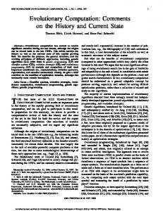
This function was also considered in Ref. 14 and provides a useful benchmark for our routines. Figures 1(a) and 1(c) depict the analytical and computed HTs of the sinc function with ␥ ⫽ 5 for orders p ⫽ 1 and 4. We used N ⫽ 256 points to sample the radius in the interval (0, 3). We can appreciate that the calculated values are quite close to the exact values. Since we must truncate
M. Guizar-Sicairos and J. C. Gutie´rrez-Vega
Vol. 21, No. 1 / January 2004 / J. Opt. Soc. Am. A
⑀1 ⫽
1 N
55
N
兺 兩f
1
⫺ f 1* 兩 .
(14)
j⫽1
For the fourth-order HT and IHT of the sinc function, we obtain ⑀ 1 ⬃ 10⫺10 (N ⫽ 100), ⑀ 1 ⬃ 10⫺12 (N ⫽ 200), and ⑀ 1 ⬃ 10⫺14 (N ⭓ 300) over the whole range of the radial variable. In the second example, we compare numerically the pQDHT with respect to the well-assessed procedure of the quasi-fast Hankel transform (QFHT) introduced by Siegman.1 To this end, we choose as test function the generalized version of the top-hat function, namely, f 1 (r) ⫽ r p 关 H(r) ⫺ H(r ⫺ a) 兴 with a ⬎ 0, where H(r) is the step function H(r) ⫽ 1 for r ⭓ 0 and H(r) ⫽ 0 elsewhere, whose analytical pth-order HT is given by f 2 共 兲 ⫽ a p⫹1
Fig. 1. Exact and computed Hankel transforms of the sinc function with ␥ ⫽ 5 for (a) p ⫽ 1 and (c) p ⫽ 4. Solid curves denote exact transforms, and crosses denote the calculated transforms. Dynamic errors are shown in (b) and (d).
the input function, the calculated transform suffers from the Gibbs phenomenon, particularly near the discontinuity; however, it can be reduced with proper windowing (apodizing). Now, a suitable measure of accuracy of the numerical method is provided by the dynamic error
冋
e 共 兲 ⫽ 20 log10
兩 f 2 共 兲 ⫺ f 2* 共 兲 兩
max兩 f 2* 共 兲 兩
册
.
(13)
This error function compares the difference between exact 关 f 2 ( ) 兴 and estimated 关 f 2* ( ) 兴 transform samples with the maximum value of the HT. The dynamic error is given in decibels and plotted on a [0, ⫺120 dB] scale in subplots 1(b) and 1(d). The error is greatest around ⫽ ␥ , i.e., near the point where the transform exhibits the discontinuity. Beyond this point, the error remains below ⫺60 dB. Successive application of the HT and the IHT to the input function f 1 will presumably return the same function. We quantify the approximation error in the numerical computation by taking the average absolute difference between the exact 关 f 1 (r) 兴 and retrieved 关 f 1* (r) 兴 functions:
J p⫹1 共 2 a 兲
.
(15)
For the calculations, we take p ⫽ 4 and a ⫽ 1 and sample the function f 1 (r) in the range r 苸 (0, 2) for N ⫽ 512 and 1024. The pQDHT requires the selection of two free parameters (R and N), whereas the QFHT needs the selection of four free parameters (typically, R, N, V, and K 2 ⫽ minimum allowed number of ‘‘points per cycle’’ in the frequency space). Since the QFHT has an inherent problem of lower-end correction, it requires a careful selection of the parameters1; thus, to minimize the missing contribution due to this problem, we have chosen V ⫽ 20 and K 2 ⫽ 2. The errors and the CPU times (two HT calculations) for the pQDHT and the QFHT are compared in Table 1. The error ⑀ 2 corresponds to the average absolute difference between the exact 关 f 2 ( ) 兴 and computed 关 f 2* ( ) 兴 transformed functions, and the error ⑀ 1 is computed with Eq. (14). For the retrieved function f 1* (r), the results obtained with the pQDFT are several orders of magnitude more precise than those produced by the standard QFHT. Conversely, the QFHT is faster, but it has lower accuracy for the calculated points. This circumstance can be explained by considering that one of the main advantages of the QFHT and of similar algorithms based on the fast Fourier transform (FFT) is that they require the storage of the kernel in the form of a vector instead of a square matrix. The number of complex multiplications for a QFHT is 4N log2 2N ⫹ 2N (see Refs. 2 and 7), and the number of real multiplications for a pQDHT is N 2 . Because one complex multiplication is almost equal to three real multiplications, it is obvious that the pQDHT is more efficient than the QFHT for the same accuracy. Table 1. Comparison of the pQDHT and the QFTT N pQDHT 512 1024 QFHT 512 1024
⑀2
⑀1
CPU Time (s)
V
1.3 ⫻ 10⫺3 4.8 ⫻ 10⫺5
2.2 ⫻ 10⫺13 2.7 ⫻ 10⫺14
0.028 0.071
128.7 256.7
3.8 ⫻ 10⫺3 1.9 ⫻ 10⫺4
1.3 ⫻ 10⫺2 6.4 ⫻ 10⫺3
0.015 0.025
20 20
56
M. Guizar-Sicairos and J. C. Gutie´rrez-Vega
J. Opt. Soc. Am. A / Vol. 21, No. 1 / January 2004
6.
Calculate the propagator25
prop ⫽ exp共i2⌬z冑 ⫺2 ⫺ ¯ 2 兲 . 7. Evaluate the input field ¯u 0 (r). 8. Calculate the HT of the input ¯ 兴. ⫽ T * 关 ¯u 0 (r) J 9. Propagating loop: for j ⫽ 1,...,nz; Propagation in Fourier space: ¯ ⫽H ¯ H
丢
(16) field:
¯ H
prop.
Calculate and store the spatial field at this step: ¯ ¯J 兲 ¯u j ⫽ T * 共 H
Fig. 2. (a) Analytical 关 f 2 ( ) 兴 and computed 关 f 2* ( ) 兴 transforms, (b) exact and retrieved functions f 1* (r). Both plots correspond to N ⫽ 1024 points sampled according to the criteria of the pQDHT and the QFHT.
In Fig. 2(a), we show the analytical 关 f 2 ( ) 兴 and computed 关 f 2* ( ) 兴 transforms in the interval 苸 关 0, 10兴 . The behavior of the retrieved functions f 1* (r) is depicted in Fig. 2(b). Note that the plot of f 1* (r) calculated with the pQDHT coincides with the exact function f 1 (r). Conversely, the observed Gibbs-phenomenon ripples in f 1* (r) computed with the QFHT result from the lower finite truncation in the transform domain (V ⫽ 20).
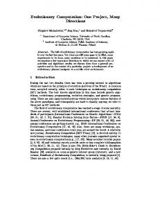
end Note that the matrix T is computed only once when the algorithm is applied to propagation and the HT is reduced to a matrix–vector multiplication. To see how the pQDHT method works in practice, we consider the focusing evolution of a trucated fourth-order Bessel beam u(r) ⫽ J 4 (k t r)exp(i4 ⫹ ikzz). The beam is normally incident on a circular lens with radius R ⫽ 4 mm and focal distance f ⫽ 0.5 m that is located at plane z ⫽ 0. The transverse and longitudinal wave numbers satisfy the relation k 2 ⫽ (2 /) 2 ⫽ k t2 ⫹ k z2 . For pth-order Bessel beams, it is known that the image in
4. WAVE PROPAGATION WITH USE OF THE pth-ORDER QUASI-DISCRETE HANKEL TRANSFORM In this section, we apply the pQDHT method to demonstrate its effectiveness for studying the propagation through axially symmetric systems. The general algorithm for propagating an input field u 0 (r) with the pQDHT method is summarized below. For clarity, overbarred variables denote column vectors. The operators 丢 and denote element-by-element multiplication and division of vectors, respectively, and * denotes the usual matrix product. 1. Choose the input parameters: p (order), R (maximum physical radius), and N (number of points). 2. Read and store the vector of roots of the pth-order Bessel function ¯␣ ⫽ 关 ␣ 1 ,..., ␣ N 兴 and the (N ⫹ 1)th root ␣ N⫹1 . See Refs. 23 and 24. 3. Calculate the radius vector ¯r ⫽ ¯␣ R/ ␣ N⫹1 , the radial frequency vector ¯v ⫽ ¯␣ /(2 R), and the limiting frequency V ⫽ ␣ N⫹1 /(2 R). 4. Generate the symmetric N ⫻ N transformation ¯ matrix T [Eq. (8)] and the column vector J ¯ ⫽ 兩 J p⫹1 ( ␣ ) 兩 /R. 5. Choose the propagating parameters: z max (propagation distance), nz (number of steps), ⌬z ⫽ z max /(nz) (increment), and (wavelength).
Fig. 3. Focusing evolution of a fourth-order Bessel beam along the plane (r, z). Physical parameters are chosen to produce a circular ring of radius 1 mm in the focal plane (at z ⫽ 0.5 m).
Fig. 4. Transverse radial intensity of the focused Bessel beam at the focal plane.
M. Guizar-Sicairos and J. C. Gutie´rrez-Vega
the focal plane corresponds to a circular ring of radius ⫽ fk t /k z modulated by the angular spectrum A( ) ⫽ exp(ip ).26 For an illumination at ⫽ 632.8 nm, we have chosen k t ⫽ 19858.32 m⫺1 to ensure an image ring with radius ⫽ 1 mm. The paraxial transmittance of the lens is given by exp关⫺ikr2/(2f )兴. The propagation of the focused Bessel beam along the plane r – z is displayed in Fig. 3. This spatial evolution was obtained by sampling the radius at 256 points and calculating the field at 300 transverse planes evenly spaced through a length of 75 cm. All numerical calculations were completed within 7.11 s on a 1-GHz personal computer with 256-Mbyte RAM. In Fig. 4, we show the radial intensity of the focusing Bessel beam at z ⫽ 0.5 m. As expected, the plot exhibits an intense peak corresponding to a circular ring at the focal plane. The good agreement between these results and results reported in Ref. 26 (obtained with twodimensional FFT-based algorithms) shows that the pQDHT method is highly accurate, and it can thus be used for studying the wave propagation through axially symmetric systems.
Vol. 21, No. 1 / January 2004 / J. Opt. Soc. Am. A
We have shown how to apply the pQDHT method in optical field propagation. Since the HT and the IHT are reduced to a simple matrix–vector multiplication, the algorithm is very fast and efficient. The advantages outlined above should make the pQDHT method valuable in optical beam propagation as well as other optical and nonoptical applications.
ACKNOWLEDGMENTS This research was supported by Consejo Nacional de Ciencia y Tecnologı´a Me´xico (grant I36456) and by the Tecnolo´gico de Monterrey Research Chair in Optics (grant CAT-007). Corresponding author Julio C. Gutie´rrez-Vega can be reached by e-mail at [email protected].
REFERENCES AND NOTES 1.
5. CONCLUSIONS In conclusion, we have proposed a discrete algorithm for computing general integer-order HTs and IHTs for a given input function. Our algorithm is a generalization of the original zero-order HT method proposed recently by Yu et al.10 In tests done with known transform pairs, agreement between exact and computed transforms was excellent. The main advantages and disadvantages of the pQDHT method are summarized as follows: • The pQDHT method does not need either to interpolate the set of data points or to use very large zero padding, as is usual in the popular backprojection and sliceprojection methods (BP-SP)5,8,12–15 and methods based on the one-dimensional FFT through an exponential change of variables (FT-EXP).1–3,19,20 In this way, the accuracy of the method depends exclusively on the size of the transformation matrix T and is not affected by the selection of additional parameters or by the choice of interpolation method, quadrature scheme, or resampling procedure. • By construction, the pQDHT method is energy preserving; i.e., the original field is retrieved after two successive applications of the HT. Other known methods (e.g., Refs. 1 and 8) have no simple retrieval expression. This property makes the pQDHT method very useful, particularly when it is applied to propagation. • The pQDHT method transforms complex inputs in one step, contrary to the BP-SP and FT-EXP methods, which typically deal with the real and imaginary contributions separately (e.g., Refs. 4, 5, and 8). • The computation of the transformation matrix T may be time-consuming; however, tables and efficient algorithms for computing the zeros of the Bessel functions can be found in the numerical literature (see, e.g., Refs. 23 and 24). A text file with the first 3000 roots of the first ten orders of the Bessel J function is available by writing to the corresponding author. Moreover, the matrix T needs to be computed only once in propagation applications.
57
2. 3. 4.
5. 6. 7. 8. 9.
10. 11. 12. 13. 14.
15. 16. 17.
A. E. Siegman, ‘‘Quasi fast Hankel transform,’’ Opt. Lett. 1, 13–15 (1977). G. P. Agrawal and M. Lax, ‘‘End correction in the quasi-fast Hankel transform for optical-propagation problems,’’ Opt. Lett. 6, 171–173 (1981). D. R. Mook, ‘‘An algorithm for the numerical calculation of Hankel and Abel transforms,’’ IEEE Trans. Acoust. Speech Signal Process. ASSP-31, 979–985 (1983). E. C. Cavanagh and B. D. Cook, ‘‘Numerical evaluation of Hankel transforms via Gaussian–Laguerre polynomial expansions,’’ IEEE Trans. Acoust. Speech Signal Process. ASSP-27, 361–366 (1979). E. W. Hansen, ‘‘Fast Hankel transform algorithms,’’ IEEE Trans. Acoust. Speech Signal Process. ASSP-33, 666–671 (1985). E. W. Hansen, ‘‘Correction to ‘Fast Hankel transform algorithms’,’’ IEEE Trans. Acoust. Speech Signal Process. ASSP-34, 623–624 (1986). V. Magni, G. Cerullo, and S. De Silvestri, ‘‘High-accuracy fast Hankel transform for optical beam propagation,’’ J. Opt. Soc. Am. A 9, 2031–2033 (1992). J. A. Ferrari, ‘‘Fast Hankel transform of order zero,’’ J. Opt. Soc. Am. A 12, 1812–1813 (1995). R. Barakat, E. Parshall, and B. H. Sandler, ‘‘Zero-order Hankel transformation algorithms based on Filon quadrature philosophy for diffraction optics and beam propagation,’’ J. Opt. Soc. Am. A 15, 652–659 (1998). Li Yu, M. Huang, M. Chen, W. Chen, W. Huang, and Z. Zhu, ‘‘Quasi-discrete Hankel transform,’’ Opt. Lett. 23, 409–411 (1998). J. Markham and J. A. Conchello, ‘‘Numerical evaluation of Hankel transforms for oscillating functions,’’ J. Opt. Soc. Am. A 20, 621–630 (2003). A. V. Oppenheim, G. V. Frish, and D. R. Martinez, ‘‘An algorithm for the numerical evaluation of the Hankel transform,’’ Proc. IEEE 66, 264–265 (1978). A. V. Oppenheim, G. V. Frish, and D. R. Martinez, ‘‘Computation of the Hankel transform using projections,’’ J. Acoust. Soc. Am. 68, 523–529 (1980). W. E. Higgins and D. C. Munson, Jr., ‘‘An algorithm for computing general integer-order Hankel transforms,’’ IEEE Trans. Acoust. Speech Signal Process. ASSP-35, 86–97 (1987). J. A. Ferrari, D. Perciante, and A. Dubra, ‘‘Fast Hankel transform of nth order,’’ J. Opt. Soc. Am. A 16, 2581–2582 (1999). S. M. Candel, ‘‘Dual algorithms for fast calculation of the Fourier–Bessel transform,’’ IEEE Trans. Acoust. Speech Signal Process. ASSP-29, 963–972 (1981). P. K. Murphy and N. C. Gallagher, ‘‘Fast algorithm for the
58
18. 19. 20. 21. 22.
M. Guizar-Sicairos and J. C. Gutie´rrez-Vega
J. Opt. Soc. Am. A / Vol. 21, No. 1 / January 2004 computation of the zero-order Hankel transform,’’ J. Opt. Soc. Am. 73, 1130–1137 (1983). B. W. Suter, ‘‘Fast nth order Hankel transform algorithm,’’ IEEE Trans. Signal Process. 39, 532–536 (1991). A. Agnesi, G. C. Reali, G. Patrini, and A. Tomaselli, ‘‘Numerical evaluation of the Hankel transform: remarks,’’ J. Opt. Soc. Am. A 10, 1872–1874 (1993). L. Knockaert, ‘‘Fast Hankel transform by fast sine and cosine transforms: the Mellin connection,’’ IEEE Trans. Signal Process. 48, 1695–1701 (2000). B. W. Suter and R. A. Hedges, ‘‘Understanding fast Hankel transforms,’’ J. Opt. Soc. Am. A 18, 717–720 (2001). G. B. Arfken and H. J. Weber, Mathematical Methods for Physicists (Harcourt–Academic, San Diego, Calif., 2001).
23. 24.
25.
26.
A. L. Garcı´a, Numerical Methods for Physics (Prentice-Hall, Englewood Cliffs, N.J., 2000). N. M. Temme, ‘‘An algorithm with Algol60 program for the computation of the zeros of ordinary Bessel functions and those of their derivatives,’’ J. Comput. Phys. 32, 270–279 (1979). The propagation of optical fields by applying the angular spectrum of plane waves is well documented in literature, e.g., J. W. Goodman, Introduction to Fourier Optics (McGraw Hill, New York, 1996). J. C. Gutie´rrez-Vega, R. Rodrı´guez-Masegosa, and S. Cha´vez-Cerda, ‘‘Focusing evolution of generalized propagation invariant optical fields,’’ Pure Appl. Opt. 5, 276–282 (2003).