sub systems such as rotor system, gear box, brake system, generator ... âBlockSim Version 7 Software. 1. .... The Birnbaum importance for the gear box ( ). B. 2.
International Journal of Computer Applications (0975 – 8887) Volume 32– No.4, October 2011
Computation of Reliability and Birnbaum Importance of Components of a Wind Turbine at High Uncertain Wind T. Sunder Selwyn, Research Scholar Department of Production Engineering, Madras Institute of Technology, Anna University,Chennai, India.
Dr. R. Kesavan , Associate Professor Department of Production Engineering, Madras Institute of Technology, Anna University, Chennai, India
ABSTRACT
General Terms
The reliable and uninterrupted power generation using wind turbines is valuable due to its environmental impacts and escalation in energy cost. The wind turbine system has a complex and repairable components. The failure of these components causes insufficient generation of power. For minimizing the lifecycle cost of a turbine and failure, it is important to evaluate the reliability level for all components. The paper deals with reliability importance analysis for major components of wind turbine system and its sub systems such as rotor system, gear box, brake system, generator, hydraulic system and yaw system. It also deals with the method of increasing the efficiency of generation by improving the life of the individual component. The system reliability is calculated through a combined study of RBD analysis, Birnbaum analytical failure criticality index and operational Criticality index for a grid connected 250 kW wind turbine. The main objective of this paper is to develop a mathematical model using a Birnbaum importance of components on the constant speed and constant pitch wind turbines with considering all the major sub assemblies to quantify the probability and reliability at high uncertain wind in Muppandal site, Aramboly pass, India
Reliability analysis and statistical importance computation of wind turbine
Keywords Reliability, System Reliability, Failure rate, Birnbaum Criticality Index, Failure Criticality Index, Operational Criticality Index. Reliability Block Diagram. –BlockSim Version 7 Software
1. INTRODUCTION In a wind turbine system whose performance depends on the performance of its components, some of these components may play a major role than others. The main purpose of determining the system reliability importance of wind turbine is to identify the weakness of the system and quantify the impact of the different components. The reliability importance measures provide a numerical rank to determine which components are more important to system reliability improvement or more critical to system failure. In order to evaluate the importance of different aspects of a wind turbine system, a set of importance measurements, including Structural Importance, Birnbaum Component Importance, Reliability Criticality Importance have been well defined. Wendai Wang et.al [1] proposed and
42
International Journal of Computer Applications (0975 – 8887) Volume 32– No.4, October 2011 defined several new reliability importance indices for complex repairable system. Fricks, R.M. and Trivedi, K.S. [2] calculated the importance of a component in a complex system by the structural importance of the system and availability of the components. Arabian Hosynabadi et.al [3] had compared the performance by quantitative failure mode and effects analysis and field fleet failure data of wind turbine components. Joseph T. Foley. et al [4] analyzed performance by using TurbSim for Vestas V90, 2MW wind turbine and obtained 1.24% impact on its power generation output with reliability improvement. Zs. J. Viharos et al [5] applied artificial intelligence techniques in the fields of supervision, failure detection and diagnosis, control, maintenance planning and decision making for increasing high level availability of wind turbines. The reliability is a function of operating time, type of failure and repair characteristics of the system and all its components. In the modern age, the higher reliability requirement systems are getting complicated because of control system, computing system, multistage interconnection and critical power system. This complexity causes frequent failures. To eliminate the failures, new reliability indices are introduced and analyzed. Tavner P.J et.al [6] assumed a constant failure rate for calculating reliability. But some components like yaw motor and brake system are not intrinsic. They deteriorate quickly due to the dynamic and fatigue load of uncertainty in wind that characterized an increasing failure rate. In this paper, mechanical subassemblies are mainly considered because they are affected heavily by dynamic loads due to frequent changes in the direction and wind velocity.
2. SYSTEM RELIABILITY The performance evaluation of wind farm is necessary and failure criticality index is essential to determine the numerical rank of individual component‟s contribution. The determination of the reliability of the individual components like the rotor (R1), gear box, (R2), brake system (R3), and generator (R4) are very important because they are connected in series. Any one of these components fall shorts then the entire system gets collapsed. R6 is the reliability of a hydraulic
system used to operate the tip mechanism and it is connected parallel to the rotor system. R7 is the reliability of the hydraulic control of the brake system. It is connected parallel to the brake system. R5 is the reliability of yaw system connected parallel to the entire system as shown in “Figure 1”. YAW SYS (C5)
ROTOR SYS (C1)
GEAR BOX (C5) (C2)
BRAKE SYS (C3)
GENER ATOR (C4)
YAW SYSTEM BLADE – TIP HYD (C6)
(C5)
BRAKE HYD (C7)
Figure: 1 Block diagram of WT components The rate of change of the system reliability depends on the components‟ reliability. It also measures the probability of a component being responsible for system failure at time t. The system reliability in this case depends on multiple component system characteristics, failure distributions, system behavior, spare availabilities etc. The system reliability RS (t) of the component at time t, is RS (t) = R5 + R1R2R3R4 + R2R3R4R6 – R1R2R3R4R6 R1R2R4 + R2R4R6R7 – R1R2R4R6R7 – R1R2R3R4R7 – R2R3R4R6R7 + R1R2R3R4R6R7 – R1R2R3R4R5 – R2R3R4R5R6 + R1R2R3R4R5R6 – R1R2R4R5R7 – R2R4R5R6R7 + R1R2R4R5R6R7 + R1R2R3R4R5R7 + R2R3R4R5R6R7 – R1R2R3R4R5R6R7 .
43
International Journal of Computer Applications (0975 – 8887) Volume 32– No.4, October 2011 The analytical relationship between a wind turbine system and its components can be obtained for complex and repairable system. For a repairable system, the reliability can depend on individual component‟s reliabilities. The system reliability in this case depends on multiple component system characteristics, such as time to time failure distributions, time to time restore distributions, system behavior, maintenance practice, logistics, and spare availabilities. So far, no analytical analysis has been made for complex wind turbine system. Therefore, Birnbaum importance of component methods is used here to obtain reliability of a complex repairable system.
3. BIRNBAUM IMPORTANCE OF COMPONENTS The value of the reliability importance depends on both the reliability of a component and its corresponding position in the system. The Birnbaum component importance is defined as by Birnbaum [7].
IB k t
R s t
R k t
Fs t
Fk t
The Birnbaum component importance is independent of the reliability. But, it is the measure of the probability of a component being responsible for failure at time t. The Birnbaum importance for the rotor is I1B t
R s t R1 t
Fs t
R S R 1 R 2 R 3 R 4 R 2 R 3 R 4 R 6 R 2 R 4 R 7 R 2 R 4R 6R 7 I1B t
R 2 R 3 R 4 R 7 R 2 R 3 R 4 R 6 R 7 R 2 R 3R 4 R 5 R 2 R 3 R 4 R 5 R 6 R 2 R 4 R 5 R 7 R 2 R 4 R 5R 6 R 7 R 2 R 3 R 4 R 5 R 7 R 2 R 3R 4 R 5 R 6 R 7
The Birnbaum importance for the gear box IB2 t is derived as follows:
R S R 2 R 1R 3 R 4 R 3 R 4 R 6 R 1R 3 R 4 R 6 R 1R 4 R 7 IB 2 t
R 4 R 6 R 7 R 1R 4 R 6 R 7 R 1R 3 R 4 R 7 R 3 R 4 R 6 R 7 R 1R 3 R 4 R 6 R 7 R 1R 3 R 4 R 5 R 3 R 4 R 5 R 6 R 1R 3 R 4 R 5 R 6 R 1R 4 R 5 R 7 R 4 R 5 R 6 R 7 R 1 R 4 R 5 R 6 R 7 R 1R 3 R 4 R 5 R 7 R 3 R 4 R 5 R 6 R 7 R 1R 3 R 4 R 5 R 6 R 7
Similarly, the Birnbaum importance for brake I3B t , generator IB4 t , Yaw system I5B t , rotor – tip hydraulic control I6B t and hydraulic brake control I7B t are calculated as follows:
R S R 3 R 1R 2 R 4 R 2 R 4 R 6 R 1R 2 R 4 R 6 R 1R 2 R 4 R 7 I3B t
R 2 R 4 R 6 R 7 R 1 R 2 R 4 R 6 R 7 R 1R 2 R 4 R 5 R 2 R 4 R 5 R 6 R 1R 2 R 4 R 5 R 6 R 1R 2 R 4 R 5 R 7 R 2 R 4 R 5 R 6 R 7 R 1R 2 R 4 R 5 R 6 R 7 .
F1 t
By partially differentiating the system reliability equation with respect to R1, R2, R3, R4, R5, R6, R7, we get the importance equation The Birnbaum importance for the rotor I1B t is derived as follows:
R S R 4 R1R 2 R 3 R 2 R 3R 6 R1R 2 R 3R 6 R1R 2 R 7 IB4 t
R 2 R 6 R 7 R1R 2 R 6 R 7 R1R 2 R 3R 7 R 2 R 3R 6 R 7 R1R 2 R 3R 6 R 7 R1R 2 R 3R 5 R 2 R 3R 5 R 6 R 1R 2 R 3R 5R 6 R1R 2 R 5 R 7 R 2 R 5 R 6 R 7 R1R 2 R 5 R 6 R 7 R1R 2 R 3R 5R 7 R 2 R 3R 5 R 6 R 7 R1R 2 R 3R 5 R 6 R 7 .
44
International Journal of Computer Applications (0975 – 8887) Volume 32– No.4, October 2011 R S R 5 1 R1R 2 R 3R 4 R 2 R 3R 4 R 6 R 1R 2 R 3R 4 R 6 I5B t
and tip brake or pitch mechanism. This system should actuate simultaneously. Otherwise it may directly attribute to some other critical failure.
R1R 2 R 4 R 7 R 2 R 4 R 6 R 7 R 1R 2 R 4 R 6 R 7 R1R 2 R 3R 4 R 7 R 2 R 3R 4 R 6 R 7 R 1R 2 R 3R 4 R 6 R 7 R S R 6 R 2 R 3 R 4 R 1 R 2 R 3 R 4 R 2 R 4 R 7 R 1R 2 R 4 R 7 I6B t
R 2 R 3 R 4 R 7 R 1R 2 R 3 R 4 R 7 R 2 R 3 R 4 R 5 R 1 R 2 R 3 R 4 R 5 R 2 R 4 R 5 R 7 R 1R 2 R 4 R 5 R 7 R 2 R 3 R 4 R 5 R 7 R 1R 2 R 3 R 4 R 5 R 7 .
R S R 7 R 1R 2 R 4 R 2 R 4 R 6 R 1R 2 R 4 R 6 R 1R 2 R 3 R 4 I7B t
R 2 R 3 R 4 R 6 R 1R 2 R 3 R 4 R 6 R 1R 2 R 4 R 5 R 2 R 4 R 5 R 6 R 1R 2 R 4 R 5 R 6 R 1R 2 R 3R 4 R 5 R 2 R 3 R 4 R 5 R 6 R 1R 2 R 3 R 4 R 5 R 6 .
The Birnbaum importance measure of a component is independent of the reliability of the component itself and it increases the rate of system reliability with respect to the individual component reliability. In addition to this complexity, most of these wind turbine systems are repairable. In such situation, where one is dealing with a large complex system composed of many components that failed and get repaired based on different distributions, control on constraints such as spares, response time and logistics is more important. The yaw mechanism is connected parallel to entire system and is used in keeping rotor of wind turbine to the predominant wind direction. The rotor tip control is not a redundant system but it is a supporting system connected parallel to the rotor which is used to control the tip mechanism of rotor. The rotor system fails when the rotor comes to standstill before tip mechanism. The failure of tip mechanism causes heavy reduction in power generation. Similarly, the hydraulic control of brake system is connected parallel to the common brake system and it is used to control the hydraulic brake only. The types of brakes used in this system are hydraulic brake, mechanical brake
4. BIRNBAUM CRITICALITY
FAILURE
Whereas the Birnbaum importance provided the probability that a given component would be responsible for the failure at time t, another measure, “component criticality importance” can be used to determine the probability that the given component is responsible for system failure before time t. This measure is given by Birnbaum [7] as
IC K
R S t
R K t
B ICK I K x
x
FK t FS t
and
RK t RS t
B ICK t I K t x
RK t RS t
For rotor Birnbaum importance of component is defined as and I1C t is derived as follows ICl t IlB t
Rl t
RS t
R 2 R 3R 4 R 2 R 3R 4 R 6 R 2R 4R 7 R 2R 4R 6R 7 R 2 R 3R 4 R 7 R 2 R 3R 4 R 6 R 7 1 R1 R 2 R 3R 4 R 5 R 2 R 3R 4 R 5R 6 1 R 5 R1R 2 R 3R 4 R 2 R 3R 4 R 6 R 2 R 4 R 5 R 7 R 2 R 4 R 5 R 6 R 7 R1R 2 R 3R 4 R 6 R1R 2 R 4 R 7 R 2 R 3R 4 R 5R 7 R 2 R 3R 4 R 5R 6 R 7 R 2 R 4 R 6 R 7 R1R 2 R 4 R 6 R 7 R1R 2 R 3R 4 R 7 R 2 R 3R 4 R 6 R 7 R1R 2 R 3R 4 R 6 R 7 R1R 2 R 3R 4 R 5 R 2 R 3R 4 R 5 R 6 R1R 2 R 3R 4 R 5R 6 R R R R R R R R R R 2 4 5 6 7 1 2 4 5 7 R1R 2 R 4 R 5 R 6 R 7 R1R 2 R 3R 4 R 5R 7 R 2 R 3R 4 R 5 R 6 R 7 R1R 2 R 3R 4 R 5R 6 R 7
45
International Journal of Computer Applications (0975 – 8887) Volume 32– No.4, October 2011 The Birnbaum importance for the gear box IC2 t is
IC2 t I 2B t
R2 t RS t
R1R 3R 4 R 3R 4 R 6 R1R 3R 4 R 6 R1R 4 R 7 R 4 R 6 R 7 R1R 4 R 6 R 7 R R R R R R R R 3 4 6 7 1 3 4 7 R1R 3R 4 R 6 R 7 1 R 2 R R R R R R R R 3 4 5 6 1 3 4 5 1 R 5 R1R 2 R 3R 4 R 2 R 3R 4 R 6 R R R R 5R R1R 2 R 3R 4 R 6 R1R 2 R 4 R 7 1 3 4 6 R1R 4 R 5R 7 R 4 R 5R 6 R 7 R 2 R 4 R 6 R 7 R1R 2 R 4 R 6 R 7 R R R R R R R R R R R R R R R 2 3 4 6 7 1 4 5 6 7 1 2 3 4 7 R1R 3R 4 R 5R 7 R 3R 4 R 5R 6 R 7 R1R 2 R 3R 4 R 6 R 7 R1R 2 R 3R 4 R 5 R R R R R R R R R R R R R R R R R 5 5 2 3 4 6 1 2 3 4 6 1 3 4 5 6 7 R R R R R R R R R R 2 4 5 6 7 1 2 4 5 7 R1R 2 R 4 R 5R 6 R 7 R1R 2 R 3R 4 R 5R 7 R 2 R 3R 4 R 5 R 6 R 7 R1R 2 R 3R 4 R 5R 6 R 7
Similarly, The Birnbaum importance for the brake system I3C t , generator IC4 t , yaw system I5C t , hydraulic system for rotor IC6 t and hydraulic system for brake system IC7 t can be stated as I3C t I3B t
R3 t
RS t
R1R 2 R 4 R 2 R 4 R 6 R1R 2 R 4 R 6 R1R 2 R 4 R 7 R 2 R 4 R 6 R 7 R1R 2 R 4 R 6 R 7 1 R 3 R1R 2 R 4 R 5 R 2 R 4 R 5R 6 1 R R R R R R R R R 5 1 2 3 4 2 3 4 6 R R R R R R R R R R 1 2 4 5 7 1 2 4 5 6 R1R 2 R 3R 4 R 6 R1R 2 R 4 R 7 R 2 R 4 R 5R 6 R 7 R R R R R R R 2 R 4 R 6 R 7 R1R 2 R 4 R 6 R 7 1 2 4 5 6 7 R R R R R R R R R R 2 3 4 6 7 1 2 3 4 7 R1R 2 R 3R 4 R 6 R 7 R1R 2 R 3R 4 R 5 R 2 R 3R 4 R 5R 6 R1R 2 R 3R 4 R 5R 6 R R R R R R R R R R 2 4 5 6 7 1 2 4 5 7 R1R 2 R 4 R 5R 6 R 7 R1R 2 R 3R 4 R 5R 7 R 2 R 3R 4 R 5R 6 R 7 R1R 2 R 3R 4 R 5R 6 R 7
IC4 t I 4B t
R4 t RS t
R1R 2 R 3 R 2 R 3R 6 R1R 2 R 3R 6 R1R 2 R 7 R 2 R 6 R 7 R1R 2 R 6 R 7 R1R 2 R 3R 7 R 2 R 3R 6 R 7 1 R 4 t R1R 2 R 3R 6 R 7 R1R 2 R 3R 5 1 R 5 R1R 2 R 3R 4 R 2 R 3R 4 R 6 R R R R R R R R R 2 3 5 6 1 2 3 5 6 R R R R R R R R R1R 2 R 3R 4 R 6 R1R 2 R 4 R 7 2 5 6 7 1 2 5 7 R R R R R R R R R 2 4 6 7 1 2 4 6 7 R1R 2 R 5 R 6 R 7 R1R 2 R 3R 5R 7 R1R 2 R 3R 4 R 7 R 2 R 3R 4 R 6 R 7 R 2 R 3R 5 R 6 R 7 R1R 2 R 3R 5R 6 R 7 R R R R R R R R R R R 1 2 3 4 5 1 2 3 4 6 7 R 2 R 3R 4 R 5 R 6 R1R 2 R 3R 4 R 5R 6 R R R R R R R R R R 2 4 5 6 7 1 2 4 5 7 R1R 2 R 4 R 5 R 6 R 7 R1R 2 R 3R 4 R 5R 7 R 2 R 3R 4 R 5 R 6 R 7 R1R 2 R 3R 4 R 5 R 6 R 7
I5C t I5B t
R5 t
RS t
R1R 2 R 3R 4 R 2 R 3R 4 R 6 R1R 2 R 3R 4 R 6 R1R 2 R 4 R 7 1 R 5 t R 2 R 4 R 6 R 7 R1R 2 R 4 R 6 R 7 1 R 5 R1R 2 R 3R 4 R 2 R 3R 4 R 6 R R R R R R R R R R 2 3 4 6 7 1 2 3 4 7 R R R R R R1R 2 R 4 R 7 R1R 2 R 3R 4 R 6 R 7 1 2 3 4 6 R R R R R R R R R 2 4 6 7 1 2 4 6 7 R1R 2 R 3R 4 R 7 R 2 R 3R 4 R 6 R 7 R1R 2 R 3R 4 R 6 R 7 R1R 2 R 3R 4 R 5 R R R R R R R R R R R 2 3 4 5 6 1 2 3 4 5 6 R R R R R R R R R R 2 4 5 6 7 1 2 4 5 7 R1R 2 R 4 R 5R 6 R 7 R1R 2 R 3R 4 R 5R 7 R 2 R 3R 4 R 5R 6 R 7 R1R 2 R 3R 4 R 5R 6 R 7
IC6 t I6B t
R6 t RS t
R 2 R 3R 4 R1R 2 R 3R 4 R 2 R 4 R 7 R1R 2 R 4 R 7 R 2 R 3R 4 R 7 1 R 6 t R1R 2 R 3R 4 R 7 R 2 R 3R 4 R 5 R1R 2 R 3R 4 R 5 R 2 R 4 R 5R 7 1 R 5 R1R 2 R 3R 4 R 2 R 3R 4 R 6 R1R 2 R 4 R 5R 7 R 2 R 3R 4 R 5R 7 R R R R R R R R R 1 2 4 7 1 2 3 4 6 R1R 2 R 3R 4 R 5R 7 R 2 R 4 R 6 R 7 R1R 2 R 4 R 6 R 7 R1R 2 R 3R 4 R 7 R 2 R 3R 4 R 6 R 7 R1R 2 R 3R 4 R 6 R 7 R1R 2 R 3R 4 R 5 R 2 R 3R 4 R 5R 6 R1R 2 R 3R 4 R 5R 6 R R R R R R R R R R 2 4 5 6 7 1 2 4 5 7 R1R 2 R 4 R 5R 6 R 7 R1R 2 R 3R 4 R 5R 7 R 2 R 3R 4 R 5R 6 R 7 R1R 2 R 3R 4 R 5R 6 R 7
46
International Journal of Computer Applications (0975 – 8887) Volume 32– No.4, October 2011
R7 t RS t
reduced drastically even though all other components of wind turbine system work well.
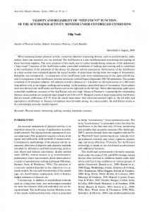
R e lia b ilit y I m p o r t a n c e V a lu e
IC7 t I7B t
ReliaSoft BlockSim 7
Static Reliability Importance Of Wind turbine at 5000 hours
0 .1 7 9
R1R 2 R 4 R 2 R 4 R 6 R1R 2 R 4 R 6 R1R 2 R 3R 4 R 2 R 3R 4 R 6 1 R 7 t R1R 2 R 3R 4 R 6 R1R 2 R 4 R 5 R 2 R 4 R 5R 6 R1R 2 R 4 R 5R 6 1 R 5 R1R 2 R 3R 4 R 2 R 3R 4 R 6 R1R 2 R 3R 4 R 5 R 2 R 3R 4 R 5R 6 R R R R R R R R R 7 1 2 3 4 6 1 2 4 R1R 2 R 3R 4 R 5R 6 R 2 R 4 R 6 R 7 R1R 2 R 4 R 6 R 7 R1R 2 R 3R 4 R 7 R 2 R 3R 4 R 6 R 7 R1R 2 R 3R 4 R 6 R 7 R1R 2 R 3R 4R 5 R 2 R 3R 4 R 5R 6 R1R 2 R 3R 4R 5R 6 R R R R R R R R R R 2 4 5 6 7 1 2 4 5 7 R1R 2 R 4 R 5R 6 R 7 R1R 2 R 3R 4 R 5R 7 R 2 R 3R 4 R 5R 6 R 7 R1R 2 R 3R 4R 5R 6R 7
100%
T ime = 5 0 0 0 H our s
50%
0 .1 4 3 0%
Reliability
0 .1 0 7
0 .0 7 2
0 .0 3 6
0 .0 0 0
YAW
GENERA
GEAR
BRAKE ROTOR
BRAKE HYD
ROTOR HYD
Figure: 2 Reliability Importance of WT Components at 5000 hours The Reliability Block Diagrams (RBDs) are used here to describe the System, the System functions and its operating states. The goal of reliability block diagrams is the determination of almost all reliability and maintainability matrices of a complete system, like reliability and its criticality importance, failure rate, and mean time to repair (MTTR) with time. The figures 2, 3 and 4 show the structural importance and Birnbaum criticality importance of the wind turbine components with respect to time. The individual reliability of a component wind turbine is shown in “Figure 5”. The “Figure 2” confirms that the component‟s failure at initial state is high in yaw system, gear box and generator and these components are highly important. It is important to identify the most problematic areas in the system. The ReliaSoft‟s BlockSim 7 software is used for this analysis and the importance of the components are computed. It has been shown that yaw system has the highest importance because in 5000 hours, the yaw system is 17.9 percent important and at 50000 hours, 85 percent important. If the yaw system fails, then the generation of electricity in a wind turbine will be
In 50000 hours, the generator has an importance of 17.5 percent and gear box has an importance of 16.8 percent. The gear box and generator are considered to be important next to yaw system. These failures are also due to fatigue failure. R e lia b ility I m p o rta n ce V a lu e
5. DISCUSSIONS
R el i aSoft Bl oc kSi m 7
0 .8 5
Static Reliability Importance 100%
50%
0 .6 8 0%
Reliability
0 .5 1
0 .3 4
0 .1 7
0
Y A W GENERA T O R GEA R BRA KE RO T O R T ime = 5 0 0 0 0
BRA KE H Y DRO T O R H Y D...
Figure: 3 Reliability Importance of WT Components at 50000 hours If the yaw system fails then the rotor is perpendicular to the direction of wind. It implies that there is a considerable reduction in harvesting energy from wind and the rotor system is subjected to a very high fatigue load. This fatigue load initiates problems in the blade, main bearing, gear box and low speed shaft.
47
International Journal of Computer Applications (0975 – 8887) Volume 32– No.4, October 2011 Re lia S o f t Blo ckS im 7
1.0
The “Figure 5” clearly illustrates that incredibly frequent failures occur in the yaw system and are 20.7317 percent because it is operating in highly fluctuating environment in which frequent changes in wind direction takes place at Mupandal site located in the Aramboly Pass. The brake system has substantial failure of 17.0732 percent and it is owing to frequent usage
Block Reliability vs Time
0.8 ROTOR GENERATOR System
0.6
ROTOR HYD SYSTEM 0.4
BRAKE SYSTEM GEAR BOX
0.2
YAW SYSTEM 0.0
140000
BRAKE HYD SYSTEM
280000
420000 Time, (t)
560000
700000
Figure: 4 Reliability of WT components with time The “Figure 4” “Figure 2” shows that the reliability of the wind turbine system and its components is based on the structural criticality importance. Hydraulic system of brake control and tip control are highly reliable and hence they have very limited failures in actual practice.
6. FAILURE INDEX (FCI)
CRITICALITY
The failure criticality index of a given component k, is given by
The field-failure assessments indicate that up to 15.4472 percent of gearbox failures may be due to high impact load of high uncertainty in the wind. The generator has a FCI of 0.130081 and the rotor has a FCI of 0.117886. The brake hydraulic system and rotor hydraulic system have low FCI because they have very less potential of failures. The other system FCI includes the failure of anemometer, nacelle, tower, control panel, etc
7. OPERATIONAL CRITICALITY INDEX (OCI) The operational criticality index can be defined as the percentage of a component‟s down time over the system down time; that is, OCI
Total down time of component when system down in 0, t Total system down time in 0, t
. FCI
Number of system failures caused by component i in (0, t) Number of system failures in (0, t)
Figure: 6 OCI of WT components Figure: 5 FCI of WT components
The results show that the rotor has a very high OCI of 0.29899 even though it has low FCI when
48
International Journal of Computer Applications (0975 – 8887) Volume 32– No.4, October 2011 compared with yaw system and brake system because of high logistic delay and mean time to repair (MTTR). The rotor failures are erratic and it is too hard to maintain spares of blade at site. If the rotor system has failed then the entire rotor system has to be dismantled at ground and it has to be re-erected by using a heavy crane. Therefore, rotor requires high MTTR. Similarly, it is evident that the generator system which includes generator and its drives has high OCI of 0.2858, because it requires high service time. It has been shown that the gear box comes next and it has a OCI of 0.1868. The yaw system and brake system have low OCI of 0.0403 and 0.0185 respectively. They have a high FCI but low OCI because of easy availability of spares at location and less restoration time.
8. CONCLUSIONS In simple systems such as a series system, it is easy to identify the weak components. But, in complex systems, this becomes quite a difficult task. It needs a mathematical approach that will provide the means of identifying and quantifying the importance of each component in the system. In this paper, the Birnbaum importance approach has been used and shows the following results: Data analysis brings about the importance of wind turbine components. It is clearly understood that if yaw system fails then the electricity generation will be reduced and the yaw system is connected parallel to the entire system. Yaw system has high structural importance, high FCI and low OCI. It can be concluded that proper inventory at site, preventive maintenance and active redundant yaw system can improve the reliability of the yaw system. Soft yaw drives may be used instead of conventional yaw drives for the wind turbines because they do not require yaw brakes and are available as a package composed of stock components. The rotor system, generator system and gear box system are connected in series, have less FCI but they do cause large downtime and replacement costs. It is generally suggested that the manufacturer should provide a good logistical support and maintain spares of blade, gear, and generator at nearby sites.
In brake, the failures are mainly due to the frequent application of brakes, during wind fluctuation. When the wind speed changes from high to low wind, then the generator system changes from the high speed generator G1 to low speed generator G2. In this process brakes are being applied to reduce the shaft speed resulting in wear in brake shoes leading to frequent failures.
9. REFERENCES [1] Wendai Wang, James Loman „Reliability importance of components in a complex system‟, IEEE 2004 proceedings annual Reliability and Maintainability symposium," Los Angeles, California, USA, January 2629, 2004. [2] Fricks, R.M. Trivedi, K.S. Importance analysis with Markov chains Page(s): 89 95 IEEE Reliability and Maintainability Symposium, 2003. Annual Date:27-30 Jan. 2003 [3]
Arabian – Hosynabadi H, oraee H. and Tavner .P.J. “Failure Modes and Effects Analysis of Wind Turbine” IET Renewable power generation, 2009, Volume 3 Issue 4 , pp 387-401
[4] Joseph T. Foley, Timothy G. Gutowski, “The Impact of Reliability on Wind Turbine LifeCycle Analysis”, in conference proceedings of WEC, Cambridge, MA 02139. [5] Zsolt János Viharos, László Monostor, Gábor Erdős, András Kovács “AI supported maintenance and reliability system in wind energy production” European Wind Energy Conference,Warsaw 2010. [6] Tavner P.J., Spinato f., Van Bussel G.J.W., Koutoulakos E.: „Reliability of different wind turbine concepts with relevance to offshore application‟. European Wind Energy Conf., EWEC2008, Brussels, 2008. [7] Birnbaum. Z. W, “On the importance of different components in a multi-component system”, University of Washington Technical Report No. 94 May 24, 1968.
49