Computation of the permeability of textiles with experimental validation for monofilament and non crimp fabrics B. Verleye1 , M. Klitz2 , R. Croce2 , D. Roose1 , S.V. Lomov3 , and I. Verpoest3 1 2 3
Dept. Computer Science, K.U.Leuven
[email protected] Inst. for Numerical Simulation, Universit¨ at Bonn
[email protected] Dept. Metallurgy and Materials Eng., K.U.Leuven
[email protected]
Summary. For the manufacturing of composite materials with textile reinforcement, the permeability of the textile is a key characteristic. Using the law of Darcy, permeability can be derived from a numerical simulation of the fluid flow, i.e. by solving the Navier-Stokes or Brinkman equations. In this paper we present the results of simulations with two different flow solvers: a finite difference NavierStokes/Brinkman solver and a lattice Boltzmann solver. The results are validated with theory and experimental data.
1 Introduction For the manufacturing of composites with textile reinforcements, the permeability of the textiles is a key characteristic. It is of particular importance for the simulation of the injection stage of Liquid Composite Molding, since the permeability has to be assigned to different positions in the preform model, when simulating the impregnation process using tools like PAM-RTM or LIMS [26, 23]. The permeability is a geometric characteristic related to the structural features of the textile at several length scales. Textiles are porous media and the permeability tensor is defined by Darcy’s law hui = −
1 K · 5 hpi , νρ
(1)
with u = u(x, y, z) the fluid velocity, ν and ρ the fluid viscosity and density, p = p(x, y, z) the pressure, hi volume averaging and K the permeability tensor of the porous medium. Equation (1) is a homogenised equation, and the information of the internal geometry of the reinforcement is taken into account
2
B. Verleye, M. Klitz, R. Croce, D. Roose, S.V. Lomov, and I. Verpoest
Fig. 1. A unit cell setup.
in K. Finite element or finite difference Darcy solvers require K as input. Unfortunately, the measurement of textile permeability is time and resource consuming [13], hence reliable numerical prediction of K is required. For the computation of K, we can determine the flow in a unit cell, since textile has a periodic pattern (Fig. 1). As textiles are also hierarchically structured materials, our model for fluid flow must take into consideration the possible porosity of the material’s yarns. Hence in the following, if the yarns are porous, we will differentiate between inter-yarn flow and intra-yarn flow. The porosity is accounted for by the permeability tensor Ktow ). In both cases we aim at a computation of the fluid velocity u and the pressure p in order to solve Darcy’s law (1) for K. In case the model is limited to creeping, single-phase, isothermal, unidirectional saturated flow of a Newtonian fluid, the inter-yarn flow is described by the incompressible Navier-Stokes equations, ½ Du ∂u 1 Dt = ∂t + (u · ∇)u = − ρ ∇p + ν∆u (2) ∇ · u = 0. The first equation states the conservation of momentum (momentum equation), the second equation states the conservation of mass (continuity equation). Intra-yarn flow depends on the local permeability tensor of the tow Ktow , and is described by the Navier-Stokes/Brinkman equations which are the Brinkman equations [24] without neglecting the convection, ½ ∂u −1 1 ∂t + (u · ∇)u + νKtow · u = − ρ ∇p + ν∆u (3) ∇ · u = 0, where u = u(x, y, z, t) and p = p(x, y, z, t) for both the Brinkman and the Navier-Stokes equations. We assume ν and ρ to be constant when describing an incompressible, Newtonian fluid and thus also in the Darcy equation (1) for the computation of K. In [29] we show that solving equations (2) to simulate the fluid flow and then using Darcy’s law (1) to calculate the permeability, yields the same numerical result as using the definition of K arising from homogenisation theory.
Title Suppressed Due to Excessive Length
3
Fig. 2. Examples of models of textile reinforcements: 2D woven; 2D woven laminate; 3D woven; UD laminate; 2-axial braid; 3-axial braid; weft-knitted; Non Crimp Fabric
A key task in permeability modelling is the characterisation of the reinforcement. For the creation of a single layer model of the reinforcement, we use the WiseTex software [30]. In practise however, often the permeability of a multi-layered reinforcement is required. Building the geometry model of a multi-layered reinforcement is a complex additional step, for which the LamTex software has been developed . The results of WiseTex and LamTex provide the input for the flow simulation tool. The software package WiseTex implements a generalised description of internal structure of textile reinforcements on the unit cell level. The description integrates mechanical models of the relaxed and deformed state of 2D and 3D woven [16, 17, 18, 15], two- and three-axial braided [19], weft-knitted [21] and non-crimp warp-knit stitched [14] fabrics (NCF) and laminates [20] (Fig. 2). All these models, including the models of deformed fabrics, use a unified description format of the geometry of the reinforcement unit cell. This format allows the calculation of physical and mechanical parameters of the fibres near an arbitrary point in the unit cell as well as their fibre volume fraction (Vf) and its direction.The reader is referred to [30] for more details. The models calculate the change of the internal geometry of the reinforcement in shear, tension and compression, accounting for local variations of the preform in the mould. It is also possible to assess the non-uniformity of the textile structure, creating a sampling of models with randomly perturbed parameters [8, 9]. In this paper we show results of calculations for woven and NCF fabrics, but the method can be applied on any of the abovementioned types of reinforcements. We develop a software package, FlowTex, for the computation of the permeability tensor of textiles. A first version of FlowTex, based on a lattice Boltzmann model for fluid flow, has been tested and validated [4]. In this article we discuss our new module for FlowTex, based on a finite difference discretisation of the Navier-Stokes equations (2) and the Navier-Stokes/Brinkman equations (3). Furthermore, we briefly explain the lattice Boltzmann model. Results of the permeability predictions with both models are compared and validated with analytical results for a model problem and with experimental
4
B. Verleye, M. Klitz, R. Croce, D. Roose, S.V. Lomov, and I. Verpoest Brinkman point
Fabric Repeat
Navier-Stokes point
Fig. 3. Top: A 2D-textile model (left) and its first order approximation on the grid (right); bottom: 3D voxel geometry.
data. Note that experimental validation is often missing in papers describing other software for permeability prediction.
2 Numerical approach 2.1 Finite difference discretisation Solution of the Navier-Stokes equations For flow simulations in the irregular geometry of a textile, we have chosen to solve equations (2) numerically on a regular staggered grid with a finite difference discretisation. An example of a textile geometry and its discretisation on a regular grid is shown in Figure 3. In the staggered grid approach, the pressure is discretised at the center of the cells, while the velocities are discretised on the edges. This discretisation leads to a strong coupling between pressure and velocities, and therefore avoids the occurrence of unphysical oscillations in the pressure. One could also use an irregular (unstructured) grid and a finite element or finite volume discretisation. However, generating the appropriate 3D meshes for complex textile geometries is difficult and time consuming for these methods.
Title Suppressed Due to Excessive Length
5
Geometry issues and boundary conditions If we neglect the intra-yarn flow, the yarns are treated as impermeable. Grid points can be in the fluid domain (’fluid points’) or in the solid yarn domain (’solid points’). At the boundaries between the fluid and the solid, no-slip boundary conditions are set. We have chosen a linear approximation of the solution at the boundaries: Vi,j,k = −Vi+1,j,k , where (i, j, k) denotes a solid point, and (i + 1, j, k) denotes a fluid point. We use a second order discretisation of the Navier-Stokes equations, but since the geometry is approximated to first order, we cannot expect second order accuracy near boundaries. Including a second order description of the geometry would not only lead to the geometry modelling problems that we avoid by using the finite difference method, but a second order approximation of the boundary imposes additional numerical stability problems. Using a first order approximation of the yarns means that fine meshes are required to obtain an accurate result. Solution of the Brinkman equations If we take the intra-yarn flow into account, the Brinkman equations (3) must be solved in the yarn points. Therefore the local permeability tensor Ktow is first calculated by the formulae of Berdichevski [5] and Phelan [22]: Ã ! µr ¶ 52 d2 1 4d2 π √ Kl = ln 2 − (3 − Vf ) (1 − Vf ) , Kt = (4) −1 32Vf Vf 4Vf 9π 2 The diameter d and the local fibre volume fraction Vf in the vicinity of the point, are provided by the WiseTex software. Kl is the permeability along the fibre, Kt stands for the permeability across the fibre. WiseTex also provides the direction of the fibres. Kl and Kt are projected onto the main directions X, Y, Z of the unit and those projections form the entries of the tensor Ktow . The Brinkman equations (3) are similar to the Navier-Stokes equations (2), and the same discretisation methods are used. In (3) the additional term νK−1 tow u can be seen as a penalisation of (2). Equation (3) converges to equation (2) for large Ktow . We solve the Brinkman equations on the whole domain with Ktow = ∞ at fluid points while for yarns Ktow is typically 10−4 ≤ Ktow ≤ 10−7 . This penalisation approach introduces a locally varying resistance force which leads to discontinuous velocities across the boundary between fluid and yarn points. To avoid numerical instabilities induced by this discontinuity, we apply a high order total variation diminishing (TVD) scheme for the convective terms discretisation.
6
B. Verleye, M. Klitz, R. Croce, D. Roose, S.V. Lomov, and I. Verpoest
Implementation A finite difference Navier-Stokes solver, NaSt3DGP, was developed by the research group of Prof. Michael Griebel at the Institute for Numerical Simulation at the University of Bonn [11],[1]. The flow solver employs a Chorin projection for the solution of the Navier-Stokes equations (2). In time-discrete notation the projection method is given by: Step 1: Solve the momentum equations for an intermediate velocity field u∗ : u∗ − un n + [u · ∇u] = ν∆un ∆t
(5)
Step 2: Project the vector field u∗ on a divergence-free vector field un+1 : ½ u∗ = un+1 + ∆t∇p (6) n+1 ∇·u =0 Applying the divergence operator to the first part of (6) results in a Poisson equation for the pressure which has to be solved in every time-step ∆t. For the solution of the Poisson equation NaSt3DGP offers several iterative solvers like SOR, Red-Black Gauss-Seidel or BiCGStab. For the approximation of (5-6), the code provides several second order TVD upwind schemes for space discretisation and an explicit Euler as well as a second order Adams-Bashfort scheme for time discretisation. Furthermore, the code works completely in parallel on MPI [2] platforms. Explicit treatment of the time-advancement of the momentum equations (5) yields a Courant-Friedrich-Levy (CFL) stability constraint for the convective terms, as well as a stability constraint for the diffusive terms depending strongly on the magnitude of the viscosity ∆t ≤
1 , 2ν∆x2
(7)
where ∆x denotes the smallest grid resolution. This is a strong restriction on the time-step size, as in permeability computations we deal with Reynolds number Re = ν1 ≈ 1. In this low Reynolds number regime the CFL condition for the convective terms usually allows for a much larger time-step than (7). Therefore, it is desirable to treat the diffusive terms implicitly. Semi-implicit solution of the Navier-Stokes equations We opted for a second-order semi-implicit discretisation of the Navier-Stokes equations (2) given by ½
un+1 −un ∆t
+ [u · ∇u]
n+ 12
1
+ ∇pn+ 2 = ν2 ∆(un+1 + un ) ∇ · un+1 = 0.
(8)
Title Suppressed Due to Excessive Length
7
In this representation [u · ∇u]
n+ 21
=
3 n+1 1 u · ∇un+1 − un · ∇un 2 2
denotes an Adams-Bashforth approximation of the convective derivative at time n + 12 and is computed explicitly, while the diffusive terms are discretised with the Crank-Nicolson scheme and are treated implicitly. With this scheme we avoid the restriction of the time step (7) as well as the solution of a nonlinear system of equations. Again, we use a fractional step method to solve (8). In order for u∗ to be a good approximation to the divergence-free velocity field un+1 , the pressure gradient is included in the momentum equations resulting in the following pressure-correction scheme as proposed by Bell et al. [3]: Step 1: Solve the momentum equations for the intermediate velocity field u∗ : (I −
1 ν∆t ν∆t n+ 1 ∆)u∗ = un − ∆t · {[u · ∇u] 2 + ∇pn− 2 − ∆un } 2 2
Step 2: Recover un+1 from the projection of u∗ by solving ½ u∗ = un+1 + ∆t∇φn+1 ∇ · un+1 = 0
(9)
(10)
Step 3: The new pressure is now found by computing 1
1
pn+ 2 = pn− 2 + φn+1 −
ν∆t ∆φn+1 2
(11)
The last term in this equation was introduced by Brown et al. [7] in order to be consistent with a second-order accurate discretisation of the NavierStokes equations. The pressure at time-level n + 1 can be recovered by an extrapolation of the pressures obtained directly from the solution procedure at time-level n + 12 and n − 12 pn+1 =
1 3 n+ 1 1 p 2 − pn− 2 . 2 2
(12)
Altogether, this kind of implicit treatment of the Navier-Stokes equations yields three modified Helmholtz equations (9) for the velocities in addition to the Poisson equation for the pressure. For the solution of these equations we employ an SSOR Preconditioned Conjugate Gradient Method. The step size is now only limited by the CFL condition and by accuracy considerations. Compared to the explicit solver, the extra computational costs per iteration for the semi-implicit solver do not outrun the gain due to the larger time steps: computations of the permeability can be obtained much faster with this method as will be shown in the next section.
8
B. Verleye, M. Klitz, R. Croce, D. Roose, S.V. Lomov, and I. Verpoest
Further Improvements In order to perform permeability calculations, we have made several further extensions to the NaSt3DGP code. For the unit cell setup, we implemented periodic boundary conditions in three directions for the velocity, and periodic boundary conditions up to a constant gradient for the pressure (Fig. 1). Discretisation of the Brinkman equations leads to a straightforward implicit implementation of the additional term νK−1 tow u in the momentum equations (5). Using the computed average velocity over the whole domain at steady state, the permeability K is derived from Darcy’s law (1). As a stopping criterion we use convergence of the permeability K up to a predefined threshold ε. Furthermore, for the input of the geometry, an interface between WiseTex and the Navier-Stokes and Brinkman code has been developed.
2.2 Lattice Boltzmann Method The lattice Boltzmann model (LBM) is a mesoscopic approach to fluid dynamics and is based on the solution of a Boltzmann equation on a regular grid. The LBM applies for a large scale of macroscopic equations. It has been shown that the LBM can be used to simultaneously solve Eqs. (2) and Eqs. (3) [25]. For our purpose, we have chosen to implement the permeability model based on the LBM D3Q19. Here, ”Q19” describes the connectivity pattern of the 3D lattice: every cell is connected with its neighbour and its next-nearest neighbours. A disadvantage of the LBM is the prescribed constant lattice step in all directions, which may result in unnecessary large lattice sizes. Note that this is not the case with the finite difference discretisation. The lattice of the LBM also contains three kinds of cells: fluid cells, solid cells and Brinkman cells. For the implementation of the non-slip boundary condition, the bounce-back rule is used. For the prediction of the flow in Brinkman cells, the local permeability is calculated as described in section 2.1 and then included in the LBM. The described LBM has been implemented as a module for the FlowTex software at the K.U.Leuven. For more details on this module, we refer to [4].
3 Results and Validation Validation tests with the lattice Boltzmann module and the finite difference module show good results. As described in the introduction, our software can be used to calculate the permeability of all textile models produced with WiseTex. We present the results of the simulation of a flow through a parallel array
Title Suppressed Due to Excessive Length
9
Fig. 4. Unit cell of the impermeable parallel square array with 62% volume fraction (left), 2D cut of the computed velocity field (right). Vf 20
62
∆x 0.1 0.05 0.03 0.025 0.1 0.05 0.03 0.025
#gridpoints 1000 8000 35937 64000 729 5832 27000 46656
#iterations 1200 3900 10100 19100 350 850 2100 2950
Kalong 0.05876 0.04881 0.04626 0.04537 0.004906 0.003374 0.003337 0.003178
Table 1. Finite difference Navier-Stokes solver: results for the parallel square array setup: number of required iterations for the Poisson solver and computed permeability for different fibre volume fractions and mesh sizes.
of cylinders, and of two realistic reinforcements for which we have experimental verification. Forward Euler time-integration, and the VONOS [28] scheme for spatial discretisation were used in the finite difference method and its performance and accuracy will be compared to semi-implicit (Crank-Nicolson) time-integration. In both cases the BiCGStab [27] method with Jacobi preconditioning was used to solve the pressure Poisson equation. 3.1 Parallel Square Array Impermeable Array For the flow through a parallel array of impermeable tows (Fig. 4), theoretical, numerical and experimental data are available [31],[10]. Results can be found for different fibre volume fractions (Vf), i.e. different radii (R) of the cylinders. Figure 5 shows the theoretical permeability, together with the calculated permeability, both for flow along the cylinders and for transversal flow. The graph also shows a comparison between the permeabilities obtained with the finite difference Navier-Stokes solver and the lattice Boltzmann method. For the example of two volume fractions, Table 1 shows the calculated permeabilities for different grid spacings: the permeability converges, as ∆x decreases.
10
B. Verleye, M. Klitz, R. Croce, D. Roose, S.V. Lomov, and I. Verpoest
Fig. 5. Permeability for the parallel square array setup with different fibre volume fractions. Full lines: theoretical permeability; circles: lattice Boltzmann results; squares: finite difference Navier-Stokes results.
#iter. Poisson #iter. Helmholtz ∆t Kx (mm2 ) Comp. Time
Explicit
Semi-Implicit
187713 0 3.12 · 10−5 3.784 · 10−3 50m23s
14309 893 9.37 · 10−4 3.774 · 10−3 03m37s
Table 2. Computational results of the semi-implicit Adams-Bashforth-CrankNicolson vs. the explicit Forward Euler method.
On a finer mesh more iterations for the Poisson solver are required (Table 1) because of two reasons. First, a finer mesh requires a smaller time-step, and therefore, more time-steps have to be taken. In the semi-implicit case the time-step may not be chosen much larger than the local mesh size, in order to obtain accurate results and in the explicit case it has to satisfy the even stronger restriction (7). Second, the preconditioned BiCGStab scheme for the Poisson equation converges more slowly to a solution on a finer mesh [6], so in each time-step more iterations are required. Semi-implicit calculations Semi-implicit and explicit time-stepping are compared for an impermeable array of cylinders with a fixed volume fraction of 60% (Table 2). Permeability calculations are carried out on a (403 ) grid. Stopping criterion is convergence of the permeability. Both calculations are performed on an Intel(R) Xeon(TM) CPU, 3.20GHz.
Title Suppressed Due to Excessive Length
11
Fig. 6. Permeability of a Parallel Square Array with different local permeabilities.
Fig. 7. Two layer model of the monofilament fabric; left: no nesting,right: maximum nesting
The time-step size for the semi-implicit calculations is 30 times larger than for the explicit case. This does not result in a speed up in computational time of the same factor because of the extra costs of solving three Helmholtz equations per time-step. Still, in this case, the implicit solver is about 14 times faster than the explicit solver. Both methods result in accurate permeability values. Permeable array Figure 6 shows the results of permeability predictions with the NavierStokes/Brinkman solver. For a fixed volume fraction (60%), the permeability is calculated for different cylinder permeabilities Ktow . For large Ktow , the permeability of the unit cell increases to the permeability of an empty cell. As Ktow decreases, the cylinders become more and more solid and the unit cell permeability converges to the permeability of an impermeable array. 3.2 Monofilament fabric The Monofilament fabric Natte 2115 is a more realistic structure which is close to actual textile reinforcements, and for which permeability is experimentally
12
B. Verleye, M. Klitz, R. Croce, D. Roose, S.V. Lomov, and I. Verpoest
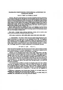
Fig. 8. Permeability Kx of the Natte textile in function of the grid spacing ∆x Model
Permeability (mm2 )
Single layer 3.44 E−04 Random nesting 3.24 E−04 ± 1.03 E−04 Maximum nesting 1.54 E−04 Experimental 2.7 E−04 ± 10% Table 3. Results for the Monofilament Fabric with different nesting
validated. The full description of the Monofilament Fabric Natte 2115 testfabric can be found in [13, 12]. The yarns are impermeable, so the NavierStokes equations are solved. Figure 7 shows two layers of the WiseTex model of the textile with no nesting, and on the right the output of the LamTex software, with the two layers maximally nested. Table 3 compares the results of calculations on the single layer model, the two layer model with maximum and random nesting with the experimental result. The permeability of the model with random nesting is the average of 15 calculations on models with different random nesting. Calculations are carried out with semi-implicit as well as explicit time-integration. Figure 8 shows, for the single layer model, that the predicted permeability depends strongly on the grid spacing. The first order discretisation of the geometry leads to a slightly different actual geometry. Hence on a coarse grid, we actually solve a different problem, which leads to a higher permeability. Furthermore, with semi-implicit time-stepping the calculated permeability is smaller than in the explicit case, but for a finer mesh this difference tends to zero. 3.3 Non crimp fabric Figure 2 shows -among others- a model of a non crimp fabric. We present experimental verification for two different fabrics: a bi-axial and a quadriaxal
Title Suppressed Due to Excessive Length
13
Fig. 9. Numerical and experimental permeabilities of the non crimp fabric Preform name
Description
Biaxial
Bidiagonal carbon fabric Quadriaxial carbon fabric
Quadriaxial
Number of Orientation Mass of the Stitching plies of plies fabric pattern (degrees) (g/m2 ) 2
+45;-45
322 ± 16
4
0;-45;90;-45 629 ± 31
Tricot
Tricot-warp
Table 4. Parameters of the non crimp fabrics
carbon fabric. Table 4 shows the most important parameters to describe the fabrics; for a more detailed description we refer to [14]. On the bi-axial structure, three institutes performed the experiments: MTM (K.U.Leuven), EPFL (Lausanne) and Ecole des Mines (Douai). The experimental results are shown in Figure 9, together with the permeabilities computed by solving the NavierStokes/Brinkman equations (3). The parameters of the computational unit cells are sumerized in tabel 5. The table also shows a comparison between the permeabilities computed with (NS/B) and without (NS) the intra-yarn flow taken into account. Note that the resolution in z-direction is higher than the resolution in x, y-direction.
4 Conclusions We presented a software package for the computation of the permeability of textile reinforcements.
14
B. Verleye, M. Klitz, R. Croce, D. Roose, S.V. Lomov, and I. Verpoest
Preform name
∆x
Biaxial Biaxial
0.04 0.04 0.03 3.4 4.92 0.055 0.055 0.045 8.195 5.06
∆y
∆z
x
y
z
Kxx NS
Kxx NS/B
0.45 2.78 E-04 5.04 E-04 0.945 5.27 E-04 9.44 E-04
Table 5. Parameters of the non crimp fabrics unit cells and computational results. Units are mm and mm2
First a textile model is designed with the WiseTex or LamTex software. An accurate model is required as slight differences in the model lead to different permeabilities. Using the model resulting from WiseTex or LamTex, flow simulations are performed to predict the permeability. We have chosen to solve the Navier-Stokes and Navier-Stokes/Brinkman equations with the finite difference method and we compare the results with those obtained with a lattice Boltzmann method. Both methods were validated on a parallel array of cylinders. For impermeable arrays, the calculated permeability can be compared with theoretical results. Both the finite difference Navier-Stokes and the lattice Boltzman solver give accurate results for such setup. For permeable arrays theoretical results are not available, but the predictions of the Brinkman solver, including the intra-yarn flow, show good convergence to the results of the Navier-Stokes solver in case the permeability of the array tends to zero. To evaluate permeability calculations for real textiles, we presented validation results for a monofilament fabric Natte and a Non Crimp Fabric fabric, for which experimental data are available. In order to speed up permeability computations we implemented a semiimplicit pressure-correction method for the finite difference Navier-Stokes solver. With this numerical method a substantial reduction of computation time has been observed in all calculations.
5 Further research Further validation of the software is necessary. Textile design engineers not only need correct permeability results, they also need them fast during the design process. Although the software is already useful for designing purposes, we will include more numerical improvements to speed up the calculations. The presented results are accurate. However, permeability is sometimes slightly overestimated. This may be due to the models used, which ignore physical phenomena (e.g. moving textile boundaries) as well as to the first order discretisation of the boundaries. The improvement and extension of these models towards e.g. higher order boundary conditions is part of our ongoing research.
Title Suppressed Due to Excessive Length
15
Acknowledgements This research is part of the IWT-GBOU-project (Flemish government, Belgium): Predictive tools for permeability, mechanical and electro-magnetic properties of fibrous assemblies: modeling, simulations and experimental verification. Roberto Croce and Margrit Klitz were supported in part by the Sonderforschungsbereich 611 Singul¨ are Ph¨ anomene und Skalierung in Mathematischen Modellen sponsored by the Deutsche Forschungsgemeinschaft. The authors thank V. Michaud from EPFL, Lausanne, for the permission to use data from figure 9.
References 1. http://wissrech.iam.uni-bonn.de/research/projects/nast3dgp. 2. http://www-unix.mcs.anl.gov/mpi/. 3. J.B. Bell, P. Colella, and H.M. Glaz. A second-order projection method for the incompressible navier-stokes equations. Journal of Computational Physics, 85:257–283, 1989. 4. E.B. Belov, S.V. Lomov, Ignaas Verpoest, Teo Peeters, and Dirk Roose. Modelling of permeability of textile reinforcements: lattice boltzmann method. Composites Science and Technology, pages 1069–1080, 2004. 5. A.L. Berdichevski and Z. Cai. Preform permeability predictions by selfconsistent method and finite element simulation. Polymer Composites, 14(2):132–43, 1993. 6. W.L. Briggs, H. Van Emden, and S.F. McCormick. A Multigrid Tutorial, Second edition. SIAM,Philadelphia, 2000. 7. D.L. Brown, R. Cortez, and M.L. Minion. Accurate projection methods for the incompressible navier-stokes equations. Journal of Computational Physics, 186:464–499, 2001. 8. F. Desplentere, S.V. Lomov, and I. Verpoest. Influence of the scatter of perform permeability on the mould filling: Numerical simulations. In Proceedings of the 25th International SAMPE Europe Conference, pages 331–336, Paris, March 2004. 9. F. Desplentere, S.V. Lomov, D.L. Woerdeman, I. Verpoest, M. Wevers, and A. Bogdanovich. Micro-ct characterization of variability in 3d textile architecture. Composites part A, 65:1920–1930, 2005. 10. B.R. Gebart. Permeability of unidirectional reinforcements for rtm. Journal of Composite Materials, 26(8):1100–33, 1992. 11. M. Griebel, T. Dornseifer, and T. Neunhoeffer. Numerical Simulation in Fluid Dynamics, a Practical Introduction. SIAM,Philadelphia, 1998. 12. K. Hoes. Development of a new sensor-based setup for experimental permeability identification of fibrous media. PhD thesis, Vrije Universiteit Brussel, 2003. 13. K. Hoes, D. Dinesku, M. Vanhuele, H. Sol, R. Parnas, E.B. Belov, and S.V. Lomov. Statistical distribution of permeability values of different porous materials. In H. Sol and J. Degrieck, editors, 10th European Conference on Composite Materials (ECCM-10), 2001.
16
B. Verleye, M. Klitz, R. Croce, D. Roose, S.V. Lomov, and I. Verpoest
14. S.V. Lomov, E.B. Belov, T. Bischoff, S.B. Ghosh, T. Truong Chi, and I. Verpoest. Carbon composites based on multiaxial multiply stitched preforms. part 1: Geometry of the preform. Composites part A, 33(9):1171–1183, 2002. 15. S.V. Lomov, T. Truong Chi, I. Verpoest, T. Peeters, D. Roose, P. Boisse, and A. Gasser. Mathematical modelling of internal geometry and deformability of woven preforms. International Journal of Forming Processes, 6(3-4):413–442, 2003. 16. S.V. Lomov, A.V. Gusakov, G. Huysmansa, A. Prodromou, and I. Verpoest. Textile geometry preprocessor for meso-mechanical models of woven composites. Composites Science and Technology, 60:2083–2095, 2000. 17. S.V. Lomov, G. Huysmans, Y. Luo, R. Parnas, A. Prodromou, I. Verpoest, and F.R. Phelan. Textile composites models: Integrating strategies. Composites part A, 32(10):1379–1394, 2001. 18. S.V. Lomov, G. Huysmans, and I. Verpoest. Hierarchy of textile structuresand architecture of fabric geometric models. Textile Research Journal, 71(6):534– 543, 2001. 19. S.V. Lomov, A. Nakai, R.S. Parnas, S. Bandyopadhyay Ghosh, and I. Verpoest. Experimental and theoretical characterisation of the geometry of flat two- and three-axial braids. Textile Research Journal, 72(8):706–712, 2002. 20. S.V. Lomov, I. Verpoest, T. Peeters, D. Roose, and M. Zako. Nesting in textile laminates: geometrical modelling of the laminate. Composites Science and Technology, 2002. 21. M. Moesen, S.V. Lomov, and I. Verpoest. Modelling of the geometry of weft-knit fabrics. In TechTextil Symposium, pages CD–Edition, Frankfurt, 2003. 22. F.R. Phelan and G. Wise. Analysis of transverse flow in aligned fibrous porous media. Composites part A, 27A:25–34, 1996. 23. P. Simacek and S.G. Advani. Desirable features in mold filling simulations for liquid composite molding processes. Polymer Composites, 25(4):355–367, 2004. 24. J.C. Slattery. Momentum, energy and mass transfer in continua. McGraw-Hill, New York, 1972. 25. MAA Spaid and F.R. Phelan. Lattice boltzmann method for modeling microscale flow in fibrous porous media. Physics of fluids, 9(9):2468–74, 1997. 26. F. Trochu, E. Ruiz, V. Achim, and S. Soukane. Advanced numerical simulation of liquid composite molding for process analysis and optimization. Composites Part A-Applied Science and Manufacturing, 37(6):890–902, 2006. 27. H. van der Vorst. Bi–cgstab: A fast and smoothly converging variant of bi–cg for the solution of nonsymmetric linear systems. SIAM J. Sci. Stat. Comput., 13:631–344, 1992. 28. A. Varonos and G. Bergeles. Development and assessment of a variable–order non–oscillatory scheme for convection term discretization. Int. J. Numer. Methods Fluids, 26:1–16, 1998. 29. B. Verleye, M. Klitz, R. Croce, M. Griebel, S.V. Lomov, D. Roose, and I. Verpoest. Predicting the permeability of textile reinforcements via a hybrid navierstokes/brinkman solver. In 8th International conference on flow processes in composite materials, Douai, France, 2006. 30. I. Verpoest and S.V. Lomov. Virtual textile composites software wisetex: integration with micro-mechanical, permeability and structural analysis. Composites Science and Technology, 65(15-16):2563–2574, 2005. 31. J.V.D. Westhuizen and J.P. Du Plessis. Quantification of unidirectional fiber bed permeability. Journal of Composite Materials, 28(7):38–44, 1994.
Title Suppressed Due to Excessive Length
17