work, we explore the variety of available coupled oscillator architectures. Additionally, we evaluate some basic computation using these architectures in the ...
2014 IEEE Computer Society Annual Symposium on VLSI
Computational Architectures Based on Coupled Oscillators Matthew Cotter, Yan Fang†, Steven P. Levitan†, Donald M. Chiarulli‡, and Vijaykrishnan Narayanan Department of Computer Science & Engineering, The Pennsylvania State University, University Park, PA 16802 † Department of Electrical and Computer Engineering, University of Pittsburgh, Pittsburgh, PA 15260 ‡ Department of Computer Science, University of Pittsburgh, Pittsburgh, PA 15260 Recently, the use of coupled electrical and electromechanical oscillator architectures has been explored in the area of associative memories. It has been shown that coupled oscillator arrays are useful in associative memories[13, 14], and CMOS ring oscillators can be useful in the emulation of such arrays[15].
ABSTRACT Recent advances in device technology have opened the door to exploration of new computing paradigms. These paradigms are geared to exploit the behavior of emerging devices such as coupled oscillator arrays. Coupled oscillators are one such device technology that offloads some of the computational complexity to the devices exploiting the physics of the device to perform computation, rather than relying purely on Boolean logic. In this work, we explore the variety of available coupled oscillator architectures. Additionally, we evaluate some basic computation using these architectures in the image processing domain, with an eye towards more complex algorithms and applications.
In section 2, we explore a variety of existing devices and technologies from which can enable computation using coupled oscillator architectures. Section 3 describes supporting circuitry necessary for providing an interface with such oscillator architectures. Section 4 describes how these devices can be used to perform computation of some complex tasks in areas such as pattern analysis and computer vision. We also explore how the performance of these devices compares with similar implementations running in software on general purpose processors using some common image processing tasks for comparison.
Categories and Subject Descriptors Algorithms, Coupled oscillators, Performance, Design
General Terms
2. OSCILLATOR TECHNOLOGIES 2.1 CMOS Oscillators
Algorithms, Performance, Design, Theory.
Keywords
There are a variety of devices and technologies that have been demonstrated to exhibit oscillatory behaviors. Used in the operation of many nanoscale systems, CMOS oscillators are a critical part of many applications in analog and digital circuitry. CMOS ring oscillators are the foundation on which Phase-Locked Loop (PLL) clock synthesizers are based. These oscillators enable other hardware to perform computations, while doing virtually no computation themselves. However, such oscillators can instead work together to perform computation rather than simply enable it. Voltage controlled oscillators (VCOs) modulate the behavior of a ring oscillator based on an input control voltage differential.
Coupled oscillators, frequency locking, phase locking.
1. INTRODUCTION Oscillators are well-known and well-studied in many real-world physical[1, 2, 3, 4, 5, 6] systems. This type of oscillatory behavior is critical in many nanoscale[7, 8] systems as well. CMOS oscillators provide the foundation for many applications in both digital and analog circuitry. Ring oscillators, comprised of a closed loop network of CMOS inverters provide the foundation for Phase-Locked Loop (PLL) clock synthesizers. These CMOS oscillators exist in a wide variety of flavors, controlled by a voltage differential.
Based on ring oscillators, VCO CMOS oscillators consist of networks of MOSFET transistors for signal generation and control. The operating voltages for CMOS VCOs often scale with process technologies. In[16], a VCO ring oscillator is demonstrated capable of operating between 8.5 and 14 GHz.
The primary motivation for our study is the emergence of variety of new devices that promise efficiency in power and performance as well as good scalability to very small feature sizes. Among such oscillator devices are Resonant Body Transistors (RBTs)[8], Spin-Torque nano-oscillators (STNOs)[7, 9, 10], and MetalInsulator Transition (MIT) materials.
2.2 Emerging Technologies Additional advances in materials research has enabled new classes of device technologies exploiting several nano-scale phenomena such as mechanical movement in Nanoelectromechanical Switching (NEMS) devices, magnetic fields in Spin-Torque Nano Oscillators (STNOs), and transition of physical characteristics in Metal-Insulator Transition materials (MIT). A brief comparison of these oscillator technologies and their properties is given alongside those of CMOS VCO oscillators in Table 1.
Such devices have been demonstrated to provide improvements to existing CMOS oscillators in many ways. However, the use of these oscillator devices have primarily focused on improving the use of existing oscillator architectures in common applications such as PLLs[11], microwave generation, high-sensitivity measurements, and data transmission systems. Oscillators have also found use in the fields of neuroscience and image processing[12]. Most notably those works have focused on using oscillatory behavior in a system patterned after a neural network in which neurons (oscillators) are connected to provide both feed-forward and feedback paths for computation.
978-1-4799-3765-3/14 $31.00 © 2014 IEEE DOI 10.1109/ISVLSI.2014.87
2.2.1 Resonant Body Transistors NEMS devices, while functionally similar to traditional transistors, differ in that they rely on mechanical movement for operation. Resonant Body Transistors (RBTs) are a type of NEMS device that are designed to use electrically transduced motion to 130
modulate the current through the transistor[8]. The RBT is controlled by a pair of gate voltages to bias the FET as well as activate the resonator.
change the physical properties of the materials. Materials used in MIT devices have the capability to act as either conducting metals or insulators depending on the conditions. As shown in [20], there are a wide variety of materials which exhibit this phase transition characteristics, with several control mechanisms for triggering these transitions via changes in temperate, pressure, and electrical voltage and current.
RBTs have been demonstrated to exhibit resonant frequencies around 100MHz [11]. These devices operate on input voltages in the range of 4-10V[8, 11] with device sizes on the scale of 1 um[11].
Many of these MIT materials, have been observed to exhibit oscillatory characteristics by triggering these metal-insulator transitions. Materials whose transitions may be triggered electrically[24] are excellent for use in oscillator devices at room temperature. These devices, in series with an external resistance, may be controlled via an input voltage. The current/voltage over the device induces a state transition from metal to insulator, or vice versa. This results in a corresponding change in the current through (voltage across) the device, causing the device state to transition again. The frequency of this oscillation may be controlled via the magnitude of the external resistance.
Coupling between RBTs can be accomplished using feedback mechanisms directing the outputs to modulate the gate voltage of neighboring devices.
2.2.2 Spin-Torque Nano-Oscillators The operation of Spin-Torque Nano-Oscillators is founded on the persistent interaction between electrical current in the presence of magnetic fields. This interaction leads to self-sustaining oscillatory changes in the resistance of the device. Oscillations of STNOs vary as a function of the device parameters, such as the relative orientations between the fixed, free, and applied magnetic fields. For a given device, the frequency of oscillation is controlled by the DC current driving the device. This current, typically small in the mA range, can induce oscillations of 1 to 100 GHz[17].
Current MIT oscillator devices are larger (5-10um) and operate at higher (6-15V) voltages than traditional systems[20, 21, 22, 23], but research has shown progress towards scaling down the operating conditions of these devices. These oscillators operate with an input voltage offset added to an input bias. This offset provides some control over oscillation of the device, in addition to control afforded by the external resistance.
Coupling behavior between STNO devices can be achieved in multiple ways. Through simple electrical coupling, interconnect is used in order to allow the output of one oscillator to modulate the drive current of neighboring oscillators. Due to the very small magnitude changes in the resistivity of STNOs due to oscillations, this coupling is weak and may not be sufficient without additional circuitry to amplify the oscillator signals.
The oscillations in many of these devices are slow (1MHz or less), making fine-tuned detection of synchronicity difficult. However, along with the continued scaling of these devices, the oscillation frequency is expected to increase, enabling the finely tuned measurements necessary for some computational tasks.
Magnetic coupling is also possible with STNOs. The magnetic spin-waves emitted by oscillators can influence the magnetic fields of nearby oscillators and thereby affect their behavior. The degree of influence is proportional to the distance between devices. Individual STNO devices are small, on the order of 10s of nanometers[17], comparable to modern transistors. However, it has been shown that significant spin-waves are influential at distances up to 500nm[9]. Therefore, the density of devices is limited by the strength and topology of the desired coupling effects. As this is a fabrication-time decision, STNOs that are magnetically coupled may not be useful for architectures in which dynamic coupling is desirable. However, due to the limited sphere of influence, asymmetric array topologies may be designed to selectively vary coupling between devices tailoring the array for specific tasks.
These oscillator devices may be coupled electrically using resistive or capacitive coupling. When the output terminals of the devices are coupled, the voltage across the oscillators are modulated which in turn changes the frequency of oscillation. The strength of the coupling can be controlled by changing the magnitude of the coupling element (capacitance or resistance). Use of devices whose characteristics can be modified electrically, such as transistors, for the capacitive/resistive coupling element could enable dynamic configuration of the coupling effects between oscillator nodes.
3. INTERFACE CIRCUITRY Computation performed these oscillator architectures is achieved by exploiting the natural oscillation physics of the devices as well as the coupling effects between oscillator nodes. These effects combine to force synchronization between the oscillators. The degree of similarity between the oscillator inputs can be measured
2.2.3 Metal-Insulator Transition Materials Another oscillator device technology, based on Metal-Insulator Transition (MIT) materials exploits the capability to dynamically
Table 1: Summary of Oscillator Technologies Device Technology
Input
Device Size
Output
Coupling
CMOS VCO Ring Oscillators[16, 18]
Differential Voltage (10GHz
Output-connected feedback via tunable resistive coupling for input modulation
Spin Torque NanoOscillators [7, 9, 10, 17, 19]
DC Current: 4-20 mA
~ 100 nm
Voltage: ~1-10mV Frequency: 1-10GHz
Metal Insulator Materials [20, 21, 22, 23, 24]
DC Voltage:2-15V External Resistance: k-M� scale
~ 5-10 um
Voltage: ~6V Frequency: < 1MHz
131
Weak coupling via output-connected feedback (Not tunable w/o amplifier) Strong coupling via magnetic spin waves (strength proportional to distance, up to 500 nm) Resistive or capacitive output coupling for modulating control voltage
as a function of this synchronization.
condition, a timing measurement mechanism such as the counter described for frequency measurement or charge path for phase detection can be used to determine the time required for the signals to lock.
The state of the computational variables in such a system are stored in the oscillation characteristics. As a result, some supporting circuitry is necessary to convert between the digital/analog and oscillator domain.
Another means of detecting synchronization amongst oscillators is described in [15]. In this work, an integrate-and-fire style circuit is used to measure the speed with which an oscillator array converges. The charging of output nodes from the summed oscillator outputs results in more rapid charging for oscillators more in sync—there is more constructive interference between signals that are closer to locked in synchrony.
3.1 Input Circuitry The nature of the described devices is such that their oscillation characteristics are driven by a differential input voltage. This differential may either drive the oscillator directly (CMOS VCOs, RBTs), create a drive current (STNOs), or influence a voltage offset (MIT).
4. COMPUTATIONAL TASKS
The magnitude of the drive voltage or current can be directly derived from the corresponding input value. For example, in image processing tasks, these inputs may be derived from the magnitude of the pixel intensities. The output of a device, such as an analog image sensor may produce this input directly for the oscillators.
Coupled oscillator arrays have been shown to be useful in template matching functions for associative memories [13, 14, 15, 17]. The template matching function effectively returns the vector that corresponds to the minimum distance between the input and reference N-dimensional input vectors. In terms of oscillator operation, the vectors are translated into differential or DC inputs, depending on the oscillator technology. Low distance between the vectors, corresponds to small differences in the input, resulting in similar initial conditions for the oscillators. Under these conditions, the oscillators will lock to a common phase or frequency more quickly than in situations with a larger dispersion of initial conditions.
3.2 Output Circuitry Oscillator devices may achieve synchronization via frequencylocking or phase-locking. There are a variety of ways that this locking can be used to measure the degree of match between inputs. The magnitude of the signal locking, either in raw value or in divergence from a baseline, can provide some measure of how similar the inputs are. However, for larger arrays, detection circuitry may be too cumbersome to be associated with each node in the array. In these cases, another useful metric is the speed with which the locking occurs. Another means of mitigating the impact and complexity of this circuitry is through the use of multiple smaller arrays working together. An example of this oscillator computation, akin to separable filters, is given in section 4.
This type of high-dimensional distance metric can be used in a variety of algorithms such as sequence analysis and clustering. Additionally, this type of metric may also serve as a replacement in some algorithms were correlation is used, such as HMAX[28], as it also produces an effective degree-of-match metric. As shown in [15], oscillator-based template matching selects the template vector which causes the oscillators to achieve synchronization in the shortest amount of time. Using a similar computational structure, it is interesting to examine cases where the desired measure is a degree of dissimilarity. This type of outlier detection can be very useful in image processing algorithms such as saliency.
3.2.1 Frequency and Phase Measurement There exist a variety of circuits to detect either the phase or frequency of a signal. For many of the explored oscillators, the magnitude of the oscillations may be large enough to be measured by conventional CMOS detector circuits. However, in the case of STNOs, an amplifier may be necessary to make the signal large enough for recognition in the detector circuits.
4.1 Visual Attention Attentional systems are models of the primate visual system which locates regions of interest in an image for processing. This process is based on detecting those areas in an image that stand out the most from their surroundings—those that catch the eye of the viewer most readily[29, 30, 28]. The type of attentional features detected varies based on the granularity with which processing is performed.
Frequency measurement may be achieved through the use of a simple binary counter circuit. The counter is enabled for a fixed time period and incremented on each rising edge of the oscillator output. At the end of the fixed measurement interval, the value of the counter is proportional to the frequency of the oscillation. A circuit for phase measurement requires a reference signal for comparison. The circuit can be designed to generate an analog voltage proportional to the magnitude of the phase difference. The rising edge of the reference signal enables a path to charge a capacitive node. The rising edge of the measurement signal closes the path. The resulting analog voltage on the charged node is then measured and is proportional to the difference in phase between the two input signals.
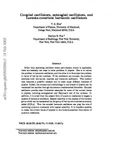
Detection of these interesting pixels using an oscillator array is based on the idea that a pixel is more interesting if it is most different from its neighbors. A sliding window approach is used for processing the image. Inputs to the oscillator array are derived from the difference between each pixel of the window and the pixel at the center of the window. For this type of processing, as the oscillator inputs are solely dependent on the window being processed, many windows may be processed in parallel for increased performance. An example of this input and parallel operation is shown in Fig. 1.
3.2.2 Signal Locking Detection In cases where the magnitude of the locked signal is not useful, a more useful measurement is the time required for the oscillators to synchronize. Typical detector circuits, such as those in [25, 26, 27], are used to perform frequency and phase comparisons in an effort to generate external control signals for correcting discrepancies between a slave signal and a reference signal.
For the results shown here, a simulation model of coupled oscillators based on the Kuramoto model [1, 3, 6, 31] was used. In this model, the oscillators achieve a phase-lock over time. The output was modeled after the time-based phase-locking detection described in 3.2.2. The parameter K in the model corresponds to a type of electrical feedback coupling described in Section 2. While
When the output control signals indicate no change is needed, the signals are said to be synchronized. Using this signal as a stop
132
result, our 3x3 array consisting of 9 oscillators is assumed to converge nearly as quickly. At ~10ns per pixel, the oscillator array would require approximately 163.8us to process the same image. However, we anticipate this performance to improve as devices scale and by exploiting the high density of integration to construct parallel arrays.
the described methods allow for independently tuned coupling, in these simulations, an all-to-all uniform coupling strength is used. The simulated Kuramoto model employed here utilizes an arbitrary time scale, and so its timing results are used for as scaling factors to compute convergence times based on data previously observed from simulated STNO device timing[10].
3x3 Osc. Array
Stabilization Detector
Fig. 1: Sliding-Window Parallel Oscillator Operation
4.1.1 Edge Detection
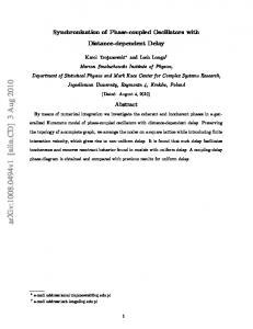
Fig. 2: Edge Detection on COIL-20 [33]
At the lowest level, the most interesting features in an image are edges, marking the boundaries between sharp regions of contrast in an image. By their definition, these edge pixels are highly different from their immediate surrounding pixels and therefore this type of algorithm maps well to the proposed oscillator architectures. For edge detection based on oscillators, a simple 3x3 oscillator array was simulated, using a sliding window approach to process each pixel in the image. For each output pixel, the value is calculated as a function of the time required for the oscillator to converge. This is extracted from the results of the simulation, however, in a hardware realization, this type of output can be calculated using the phase locking detection and timing described in Section 3.2.2.
From left to right: Original Image, Canny, 3x3 Oscillator, and Manhattan Distance
For testing, a selection of images from the COIL-20 image dataset was chosen. The functional capability of the oscillators are compared to the output of the Canny[32] edge detection algorithm. For an evaluation of the performance of the oscillators, a software program was written that performs the same operation, applying a sliding window over the image, computing the sum of differences (Manhattan distance) between the pixels in each window vector. For a fair performance comparison, the software package was compiled using maximum optimizations. While this Manhattan distance computation between two vectors is not an exact mirror of the computation performed by the oscillators—the actual computation is more complex—it is a reasonable parallel as it computes a pixel-wise similarity metric. The output results of these algorithms are shown in Fig. 2.
Fig. 3: Comparison of oscillator edge detection using full array and separated arrays Top: 3x3 Oscillator output Bottom: Combination of 1x3 and 3x1 Oscillator outputs Further improvements can be achieved by separating the 3x3 window into independent 3x1 and 1x3 windows, allowing for the use of a smaller oscillator array. This allows further reduction in the area, enabling additional parallelism in operation. Without significant change in convergence time. implementing this separation of windows allows for the operation to be completed in the same time using 6 oscillators rather than nine. In addition to area savings and improved computational density, this reduction in oscillator count removes additional output circuitry, further reducing the complexity of the design and layout.
For evaluation of the quality of edge detection, a comparison of the bounding boxes that can be extracted from the resulting edges is performed. The evaluation of the bounding boxes extracted from oscillator-generated edges is performed by calculating the ratio of pixels contained in the oscillator-generated box to those pixels in the Canny-edge generated box. The bounding boxes produced by the edges detected by the oscillators overlap those derived from the Canny edges by 95 to 98% on the test images.
4.1.2 Visual Saliency By increasing the size of the oscillator array, larger regions (objects instead of edges) of interest can be detected. These detections approach an approximation of visual saliency in which objects and areas that stand out are highlighted. Using a 19x19 window, a single pass of the oscillator array produces an output which can approximate the saliency task by identifying regions of stark contrast to local neighbors. For comparison, the simulated oscillator outputs are compared to the output of a software implementation of the AIM-Saliency algorithm. Additionally, as with edge detection, simulations using separated oscillator windows as well as software implementation of the Manhattan
The software application is run against each 128x128-pixel image (shown in the left column of Fig. 2) on an Intel Xeon 1.6GHz processor. The software is able to complete the processing of the image and produce the results seen in the right column of Fig. 2 in 380us. As presented in [10], an array of 8 coupled STNO devices requires approximately 10ns to reach coherence. Based on this
133
distance computation are evaluated. These results are shown in Fig. 4 and Fig. 5.
Despite the much larger array, the synchronization time of the oscillators is not expected to change significantly, with divergence of no more than a few oscillatory cycles [33] (therefore, still on the order of nanoseconds). As a result, approximately 240us would be required to process the entire image. As in the case with the 3x3 array used for edge detection, this larger array may be separated to process 19x1 and 1x19 windows, improving area usage without major impact on performance. Processing times for the evaluated algorithms and processing models are given in Table 3. Table 2: Salient Region Detection
Fig. 4: Saliency Detection using Oscillators From left to right: Original Image, AIM-Saliency, 19x19 Oscillator, and Manhattan Distance
Image
Regions
Dandelion
1
AIM Saliency 1
Duck
1
1
1
Teddy Bear
1
1
0 (Full) 1(Separated)
Fountain
7
2
6
Oscillators 1
Table 3: Performance Evaluation Task
Image Size
Edge Detection
128x128
Saliency
192x128
Oscillators in Array
Oscillators (Per Image)
Software (Per Image)
163.8us
380us
9 (3x3) 3 (1x3, 3x1) 361 (19x19)
Fig. 5: Comparison of oscillator saliency using full array and separated arrays Top: 19x19 Oscillator output Bottom: Combination of 1x19 and 19x1 Oscillator outputs
19.8ms ~240us
19 (1x19, 19x1)
2.2ms
5. CONCLUSION
For the single-object images, the oscillator does well in isolating the most interesting parts of the image. However, as seen in the teddy bear example in Fig. 4 (third row), images without sufficient contrast can prove challenging for detection. Conversely, in processing the image of the duck (second row), the saliency algorithm marks large portions of the field as salient in addition to the region containing the duck, while the oscillators capture the sharp contrast, effectively ignoring the open field. An increased sensitivity of the separated windows is also evident in the right-most column of images in Fig. 5. The use of the separate windows is able to capture more of the bear than the full array.
Coupled oscillator architectures have been explored as a promising computational primitive. In this work, we have explored the technologies suitable for coupled oscillator architectures and their properties. These technologies include multi-device CMOS VCO ring oscillators, NEMs-based RBT switching devices, magnetic spin-torque oscillators, and metalinsulator materials. These device technologies each possess characteristics that make them attractive for a different styles of application architectures. The nature of STNOs enable simple local coupling effects due to emission of magnetic spin-waves. However, their signal characteristics may require additional circuitry to boost the amplitude of the signal. The nature of spin-waves makes dynamic coupling difficult to achieve. Resonant body oscillators may be coupled and controlled via both gate terminals, controlling both the magnitude of current oscillation as well as the frequency. MIT material-based oscillators are easily coupled and controlled through resistive and/or capacitive means, but their range of frequency operation is currently limited, relative to other technologies.
Extraction of salient regions of interest for comparison to the oscillator responses is done using the AIM-Saliency algorithm. For comparison, the results of both the AIM Saliency algorithm and the oscillator saliency detector are shown in Fig. 4. For evaluation of the saliency detection, test images were manually annotated with the location of selected objects. After processing through the software algorithm and oscillator models, the output images were examined. If more than 50% of the pixels within the regions marked as ground truth were marked as salient in the test, that region is considered to be detected. The results of detection are shown in Table 2. Using the same Manhattan distance program written for edge detection, modified to use the larger 19x19 window size, each of these 192x128-pixel images are processed in 19.8ms. Implementing the separated windows, reduces this computation to 2.2ms. For this case, using the larger window, the separation of the windows is able to provide additional speedup as the computational savings are no longer hidden by memory accesses.
These oscillator arrays have been shown previously to be effective in associative memory architectures and applications. In this work, we have shown how such oscillator arrays may also be used to perform functional computations using the common multidimensional distance metric calculations used in the associative template matching. Frequency and phase locking mechanisms are explored to extract the computational results of these arrays are explored. Further, simulations utilizing the Kuramoto model of coupled oscillation, have been shown that these device can perform effective computation of multi-dimensional distance
134
metrics between two vectors, which is a useful estimate of visual attention algorithms such as edge detection and visual saliency. Finally, these oscillator arrays are shown to perform these computations faster than optimized software counterparts.
[17] G. Csaba, M. Pufall, D. E. Nikonov, G. I. Bourianoff, A. Horvath, T. Roska and W. Porod, "Spin torque oscillator models for applications in associative memories," in Cellular Nanoscale Networks and their Applications, 2012.
6. ACKNOWLEDGMENTS
[18] M.-t. Hsieh and G. E. Sobelman, "Comparison of LC and Ring VCOs for PLLs in a 90 nm," in International SoC Design Conference (ISOCC), 2006.
This work was supported by LEAST, one of the six SRC STARnet Centers, sponsored by MARCO and DARPA. The NSF awards 1317560 and 1205618 supported equipment used in this effort. This work is also supported in part by NSF ASSIST Nanosystems ERC EEC-1160483.
7.
[19] A. Horvath, F. Corinto, G. Csaba, W. Porod and T. Roska, "Synchronization in cellular spin torque oscillator arrays," in International Workshop on Cellular Nanoscale Networks and Their Applications (CNNA), 2012.
REFERENCES
[20] Z. Yang, C. Ko and S. Ramanathan, "Oxide electronics utilizing ultrafast metal-insulator transitions," Annual Review of Materials Research, pp. 337-366, 2011.
[1] Y. Kuramoto, Chemical oscillations, waves and turbulence, SpringerVerlag, 1984.
[21] B.-J. Kim, G. Seo, Y. W. Lee, S. Choi and H.-T. Kim, "Linear characteristics of a metal-insulator transition voltage and oscillation frequency in VO2 devices," IEEE Electron Device Letters, vol. 31, no. 11, pp. 1314-1316, 2010.
[2] S. H. Strogatz, "From Kuramoto to Crawford: Exploring the onset of synchronization in populations of coupled oscillators," Physica D, vol. 143, pp. 1-20, 2000. [3] N. Chopra and M. W. Spong, "On synchronization of Kuramoto oscillators," in European Control Conference on Decision and Control, 200.
[22] H.-T. Kim, B.-J. Kim, S. Choi, B.-G. Chae, Y. W. Lee, T. Driscoll, M. M. Qazilbash and D. N. Basov, "Electrical oscillations induced by the metal-insulator transition in VO2," Journal of Applied Physics, vol. 107, 2010.
[4] T. Yamada and H. Fuijsaka, "Stability theory of synchronized motion in coupled-oscillator systems," Progress of Theoretical Physics, pp. 1240-1248, 1983.
[23] Y. W. Lee, B.-J. Kim, J.-W. Lim, S. J. Yun, S. Choi, B.-Y. Chae, G. Kim and H.-T. Kim, "Metal-insulation transition-induced electrical oscillation in vanadium dioxide thin film," Applied Physics Letters, vol. 92, 2008.
[5] J. J. Acerbon, L. L. Bonilla, C. J. P. Vicente, F. Ritort and R. Spigler, "The Kuramoto Model: A Simple Paradigm for Synchronization Phenomena," Review of Modern Physics, vol. 77, 2005. [6] N. Chopra and M. W. Spong, "On exponential frequency synchronization of kuramoto oscillators," IEEE Transactions on Automatic Control, vol. 54, no. 2, 2009.
[24] T. Driscoll, J. Quinn, G. Seo, Y.-W. Lee, H.-T. Kim, D. R. Smith, M. Di Ventra and D. N. Basov, "Current oscillations in vanadium dioxide: evidence for electrically triggered percolation avalanches," Phys. Rev. B, vol. 86, 2012.
[7] J. Akerman, "Spin torque oscillators," in International Conference on Advanced Materials, 2009.
[25] N. H. E. Weste and K. Eshragrian, Principles of CMOS VLSI Design, Addison Wesley, 1993.
[8] D. Weinstein and S. A. Bhave, "The Resonant Body Transistor," Nano Letters, pp. 1234-1237, 2010.
[26] H. Kondoh, H. Notani, T. Yoshimura, H. Shibata and Y. Matsuda, "A 1.5-V 250-MHz to 3.0-V 622-MHz operation CMOS phase-locked loop with precharge type phase-detector," IEICE Trans. Electron., Vols. E78-C, no. 4, pp. 381-388, 1995.
[9] S. Kaka, M. R. Pufall, W. H. Rippard, T. J. Silva, S. E. Russek and J. A. Katine, "Mutual phase-locking of microwave spin torque nanooscillators," Nature, vol. 437, no. 15, pp. 389-392, 2005.
[27] H. O. Johansson, "A Simple Prechared CMOS Phase Frequency Detector," IEEE Journal of Solid State Circuits, vol. 33, no. 2, pp. 295-299, 1998.
[10] M. Stan, Computing with coupled spin torque oscillator (STO) arrays, IEEE CAS Distinguished Talk Series, 2013.
[28] M. P. T. Riesenhuber, "Hiercharhical models of object recognition in cortex," Nature Neuroscience, vol. 2, pp. 1019-1025, 1999.
[11] S. T. Bartsch, A. Rusu and A. M. Ionescu, "Phase-locked loop based on nanoelectromechanical resonant-body field effect transistor," Applied Physics Letters, vol. 101, 2012.
[29] N. D. B. Bruce and J. K. Tsotsos, "Saliency Based on Information Maximization," Advances in Neural Information Processing Systems, vol. 18, pp. 155-162, 2006.
[12] M. Egmont-Petersen, D. de Ridder and H. Handels, "Image processing with neural networks -- a review," Pattern Recognition, pp. 2279-2301, 2002.
[30] N. D. B. Bruce and J. K. Tsotsos, "Saliency, attention and visual search: An information theoretic approach," Vision, pp. 1-24, 2009.
[13] S. P. Levitan, Y. Fang, D. H. Dash, T. Shibata, D. E. Nikonov and G. I. Bourianoff, "Non-Boolean associative architectures based on nanooscillators," in International Workshop on Cellular Nanoscale Networks and their Applications (CNNA), 2012.
[31] Y. Kuramoto, "Lecture notes in physics: Self-entrainment of a population of coupled non-linear oscillators," in International Symposium on Mathematical Problems in Theoretical Physics, 1975.
[14] Y. Fang, "Hierarchical associative memory based on oscillatory neural network," University of Pittsburgh, 2013.
[32] J. Canny, "A computational approach to edge detection," Transactions on Pattern Analysis and Machine Intelligence (PAMI), vol. 8, no. 6, pp. 679-698, Nov. 1968.
[15] T. Shibata, R. Zhang, S. P. Levitan, D. E. Nikonov and G. I. Bourianoff, "CMOS supporting circuitries for nano-oscillator based associative memories," in International Workshop on Cellular Nanoscale Networks and their Applications (CNNA), 2012.
[33] J. J. Fox, C. Jayaprakash, D. Wang and S. R. Campbell, "Delays, Synchronization in Relaxation Oscillator Networks with Conduction," Neural Computation, vol. 13, no. 5, pp. 1003-21, 2001.
[16] Y. A. Eken and J. P. Uyemura, "The design of a 14 GHz I/Q ring oscillator in 0.18um CMOS," in Circuits and Systems, 2004. ISCAS '04. Proceedings of the 2004 International Symposium on, 2004.
[34] S. A. Nene, S. K. Nayar and H. Murase, "Columbia Object Image Library (COIL-20)," 1996.
135