PKI-based authentication protocol and security infrastructure,. PKASSO, which is .... tion, decryption, and certificate validation in the PKI. The estimated minimum ...
1
Computationally Efficient PKI-Based Single Sign-On Protocol, PKASSO†, for Mobile Devices Ki-Woong Park, Student-Member, IEEE, Sang Seok Lim, Member, IEEE and Kyu Ho Park, Member, IEEE.
Abstract— In an attempt to expand Public Key Infrastructure (PKI) usage to a ubiquitous and mobile computing environment, we found that the deployment of the PKI on a resource constrained device such as 8 bit microprocessor leads to user-obstructive latency or an additional circuitry for the operations. To alleviate these limitations, we propose a new PKI-based authentication protocol and security infrastructure, PKASSO, which is enhanced with the single sign-on and delegation technology that is used especially for mobile devices with restricted computing power. The PKASSO offloads complex PKI operations from the mobile devices to the infrastructure so as to keep the hardware and software complexity of the devices as low as possible. In addition, even though a conventional delegation mechanism cannot support a non-repudiation mechanism against malicious user behavior, the PKASSO can provide such a mechanism by devising a referee server that, on the one hand, generates binding information between a device and authentication messages and, on the other hand, retains the information in its local storage for future accusation. We present the detailed design and performance evaluation of the PKASSO, and offer a protocol analysis in terms of user authentication latency and the completeness of the protocol. According to the performance evaluation, the authentication latency of our infrastructure (which averages 0.082 sec) is much shorter than the authentication latency of a conventional PKIbased authentication latency (which averages 5.01 sec). Index Terms— Authentication, Access controls, Public key cryptosystems.
I. I NTRODUCTION
I
N the provision of services in a ubiquitous environment, pervasive devices frequently communicate with other unknown devices, thereby exposing themselves to an unfortified and insecure environment. Security in a ubiquitous environment is therefore of immense importance, and the issue needs to be addressed to secure the privacy and confidentiality of users who live in such an environment [1]. In our ubiquitous environment, we have been developing a wearable computer, called Ubiquitous Fashionable Computer (UFC) [4], and, in its interoperable computing environments, we deployed various devices such as U-Kiosks, U-Print, and Zigbee-enabled appliances to provide users with ubiquitous services, primarily for a university campus [5]. As a fundamental way of enforcing the security of a ubiquitous environment, authentication and authorization stand out as the two most widely used mechanisms. A full realization of trustworthy ubiquitous services based on authentication and authorization in a ubiquitous computing environment requires deep understandings of the performance characteristics and the communication patterns of the mobile devices since those devices are usually endowed with limited computing power.
In particular, due to the anonymity and mobility of users in a ubiquitous environment, the pervasive devices placed for providing services should always check the identity of the mobile devices and vice versa, necessitating mutual authentication between them. Thus, fundamental security operations such as authentication, digital signatures, non-repudiation, and secure key distribution should be provided as essential services by a security infrastructure to ensure the high security of the services [2]. From a security aspect, the PKI is generally considered as the most appropriate solution for the requirements. However, the computational complexity of the PKI causes high deployment costs and a high operational overhead because asymmetric key operations of the PKI need to be performed on mobile devices. In addition, the frequency of user authentication requests increases rapidly in proportion to the number of the service devices that require mutual authentication [3]. In a mobile computing environment, the performance implications of protocol design are often accentuated by limitations in the capacity of the mobile processor and wireless network. The resources required to perform asymmetric key operations and to transmit large messages may result in unacceptable performance result and intolerable user authentication response times. By thoroughly investigating our ubiquitous environment and conventional security systems, we identified two critical limitations of a conventional PKI-based security system. The limitations and our approach are described as follows: 1) Obstructive Authentication Latency in a Mobile Device with Restricted Computing Power: There is a challenge with clients where mobile devices with restricted computing power demand frequent and dynamic authentications over the PKI. To address this latency problem, we propose a security infrastructure that is based on the PKI and a single sign-on (SSO) protocol. The proposed security infrastructure provides users with a seamless and secure system of authentication and key distribution. In the proposed infrastructure, we devised a delegation server that offloads complex PKI operations from mobile devices to the infrastructure so as to keep the hardware and software complexity of the devices as low as possible. By using the proposed authentication mechanism, we can also achieve a more secure mechanism in line with newly emerging security policy requirements without replacing hardware or software components of devices. 2) Support for Digital Signature and Non-Repudiation: Even though a digital signature mechanism and a non-
2
CA
Certificates
Users
Kerberos
- Supported Security Services
LDAP
Service Devices
Single Sign-On
No
Authentication
YES
- Supported Security Services
User Key Service Key
Certificate
Private Certificate Key
YES
Digital signature
YES
Non-repudiation
YES
Non-repudiation
No
Secure key distribution
YES
Secure key distribution
No
Users
CA : Certificate Authority LDAP : Certificate Repository
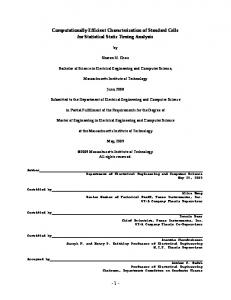
repudiation mechanism are essential functions in security applications, a conventional delegation mechanism cannot support these two mechanisms against malicious user behavior. Because user authentication transactions are already delegated, an authenticator cannot prove the fact that the authentication transactions are really intended by users. Our proposed protocol named PKASSO1 and the security infrastructure can provide the two mechanisms by means of a referee server that generates binding information between a device and authentication messages [6]. The remainder of the paper is organized as follows: In Section II, we discuss relevant works. In Section III, we present the overall system design and components of the proposed security infrastructure. In Section IV, we illustrate the proposed SSO protocol. In Section V, we evaluate the performance of PKASSO. Finally, in Section VI, we present our conclusions. II. R ELATED W ORKS To meet the demands of a a ubiquitous and mobile environment, researchers have endeavored to facilitate the deployment of a security infrastructure for e-commerce, particularly an infrastructure that can verify the authenticity of communicating parties, and establish trust among devices over the air. In this section, we briefly discuss the experimental results as we evaluate the preexisting security infrastructures in terms of the security level and the authentication latency. More comprehensive evaluations of the experimental results are described in Section V. A. PKI The PKI, which is a representative security infrastructure based on an asymmetric key, is generally considered as the most appropriate solution for e-commerce and mutual authentication, owing to its digital signature and non-repudiation features [7]. The organization of a conoventional PKI and the characteristics in terms of security level and authentication latency are illustrated in Fig. 1. Even though PKI provides † PKASSO: Public Key-based A3 -providing Single Sign On
No
Service Devices
- Minimum Authentication Latency
Fig. 1. The conventional PKI architecture and brief overview of the characteristics
1
YES
Authentication Digital signature
- Minimum Authentication Latency
= 5.01 sec
Private Key
Single Sign-On
0.19 sec
User Key
Service Key
Fig. 2. The architecture of a conventional security infrastructure based on Kerberos and the characteristics
full security features including authentication, digital signature, non-repudiation and secure key distribution, it has a severe drawback when used by a diminutive device with a restricted computing power. That is, the user service latency, which is mainly determined by the authentication latency, is exacerbated by the restricted resources of the device and by the extremely high complexity of RSA operations for encryption, decryption, and certificate validation in the PKI. The estimated minimum authentication latency in our experimental environment is about 5.01 sec on the 8 bit microprocessor [8] deployed mainly in a wireless communication module.
B. Kerberos Assisted Authentication Figure 2 shows the architecture and characteristics of a conventional authentication system based on symmetric cryptography called Kerberos [9]. Kerberos achieves significantly reduced authentication latency (minimum of 0.19 sec) than the PKI (minimum of 5.01 sec) by virtue of the lesser complexity of the symmetric key operations and the SSO mechanism. Kerberos works on the basis of tickets, namely a Ticket Grant Ticket (TGT) and a Session Grant Ticket (SGT), which serve to prove the identity of users. Whenever a user attempts to connect to a specific service, a TGT and an SGT are required for Kerberos authentication. Once a user acquires a TGT from the Kerberos server through the initial user authentication, the user can get SGTs, which enable the user to receive a service several times without additional authentication for a specific period. Kaman [9] studied how to deploy the Kerberos protocol in mobile ad hoc networks. He presented a secure key exchange scheme for use in ad hoc networks; the scheme is based on the Kerberos protocol and measures factors such as replication and elections to ensure maximum connectivity between clients and servers. This scheme cannot, however, provide a digital signature, non-repudiation, and secure key distribution for unknown devices, even though these functions are essential in security applications. These functions are precluded because Kerberos uses an authentication mechanism based on symmetric cryptography with a pre-shared secret key.
3
LDAP
CA
Certificates
Kerberos
Single Sign-On
YES
Authentication
YES
Digital signature
No
Non-repudiation
No
Secure key distribution
LDAP
CA
- Supported Security Services
- Supported Security Services Certificates
PKI-Server
YES
Single Sign-On
No
Authentication
YES
Digital signature
YES
Non-repudiation
YES
Secure key distribution
YES
Private Certificate Key
- Minimum Authentication Latency Users
Service Devices
Service Devices
Users
= 0.74 sec
- Minimum Authentication Latency = 4.75 sec CA : Certificate Authority LDAP : Certificate Repository
CA : Certificate Authority LDAP : Certificate Repository Private Certificate Key
Private Certificate Key
Fig. 3. Overall M-PKINIT architecture and brief overview of the characteristics
C. PKINIT and M-PKINIT PKINIT is an extension of a Kerberos protocol so as to enable the public key based authentication between a user and Key Distribution Center (KDC) instead of using the symmetric key based authentication. In this approach, a Kerberos server collaborates with the PKI entities, CA and LDAP directory server [10]. In addition, the PKINIT protocol aims at enhancing the security of the Kerberos protocol by using a PKI-based authentication to get a TGT by using a smaller number of public key operations than conventional PKI-based authentication. The M-PKINIT protocol is a lighter version of the PKINIT, was proposed in an attempt to reduce the significant overhead of the authentication operation and communication whenever public key protocol operations are invoked in a mobile device [11]. Figure 3 shows the organization and characteristics of the M-PKINIT protocol. This scheme can provide a secure key distribution mechanism over the asymmetric key operation, SSO through Kerberos, and it has a shorter authentication latency (minimum of 0.74 sec) than the PKI (minimum of 5.01 sec). However, it cannot provide a digital signature and nonrepudiation because each authentication for a service device is accomplished by Kerberos-based authentication. The MPKINIT protocol requires to perform public and private key operations on a user’s device whenever the user moves to another Kerberos realm to get a TGT.
Fig. 4.
Private Certificate Key
NSI architecture and brief overview of the characteristics
Asymmetric Key Authentication System
Hybrid Authentication System
Symmetric Key Authentication System
PKI
Kerberos
PKINIT
NSI
M-PKINIT PKASSO
(a) Evolution of relevant works Security Service System Single Sign-On
Authentication
Digital Signature
NonRepudiation
Secure Key Distribution
Latency
PKI
No
Yes
Yes
Yes
Yes
5.01sec
Kerberos
Yes
Yes
No
No
No
0.19sec
PKINIT
Yes
Yes
No
No
Yes
1.21sec
M-PKINIT
Yes
Yes
No
No
Yes
0.74sec
NSI
No
Yes
Yes
Yes
Yes
4.75sec
PKASSO
Yes
Yes
Yes
Yes
Yes
0.082sec
(b) Security functionality and authentication latency of relevant works
Fig. 5. The summary of relevant works; Experimental results in terms of authentication latency are described in Section V.
infrastructure server. Although the NSI provides all of the security functionality of the PKI, the authentication latency of the NSI (minimum of 4.75sec) fails to meet our system requirement with respect to authentication latency. The major reason of that failure is because the asymmetric key operations are performed on the user’s mobile device. E. Summary
D. NSI The NSI introduced a PKI server that is responsible for searching and verifying certificates on behalf of a mobile device or client [12]. Figure 4 shows the architecture and characteristics of the NSI. The PKI server provides a set of simple and abstract APIs (PKI Client API) that hide most of the complex PKI operations from a client, thereby minimizing the hardware and software complexity for a client minimal. To minimize the operational complexity for the client and server, we adopted a mechanism, called delegation [13], which has been actively studied and used in the research area of grid computing. The PKI-server and the delegation mechanism can both minimize the PKI-related computing overhead of a client by offloading the complex operations to a powerful
Figure 5 shows the technical advancement flow of the aforementioned works, and their security functionalities and authentication latency. The last row of the table clarifies our PKASSOïs design goal with respect to security functionalities to achieve and its resultant authentication latency. Even though PKI has attained to consensus that it is capable of enabling high security by providing the four essential security functionalities except for SSO, it comes at a price that the PKI-based authentication requires much more CPU cycles than the Kerberos authentication system based on a symmetric cryptography. Consequently, when PKI is used in a mobile and ubiquitous environment, the high computational complexity results in high deployment costs and operation overhead since those operations are necessarily performed on a
4
mobile device with computing power constraints. As compared to PKI, Kerberos requires relatively low computational complexity and provides SSO capability, leading to significantly reduced authentication latency, 0.19 sec. Kerberos, however is incapable of providing digital signature, non-repudiation, and secure key distribution due to its nature of asymmetric key operations and nonexistence of CA, a third party security mediator. To harness full power of PKI even in a mobile environment, M-PKINIT and NSI took a different stance by making effort to reduce the number of PKI operations or complexity of asymmetric key operations. However, M-PKINIT can not provide a digital signature and non-repudiation though they can provide secure key distribution by initial authentication over PKI. Although NSI can provide all of security functionality of PKI and reduced the PKI operation complexity on mobile device, it still suffers from intolerable authentication latency. In addition, NSI is not designed to provide SSO capability either.
CA
Certificates
Kerberos
Referee Delegation Server Server
Users
YES
Authentication
YES
Digital signature
YES
Non-repudiation
YES
Secure key distribution
YES
Service Devices
- Minimum Authentication Latency = 0.082 sec -
Private Certificate Key
Fig. 6.
A. The PKASSO Design Philosophy
We incorporated the PKINIT protocol into our system as an underlying security infrastructure in an attempt to provide a secure key distribution and a way to efficiently and costeffectively manage a large number of devices and sensors in a ubiquitous environment. As described in Section II, the PKINIT protocol is an extension of the Kerberos protocol so as to enable the public key based authentication between a user and key distribution center instead of using the symmetric key based authentication. However, the PKINIT protocol has two drawbacks: first, it cannot provide a digital signature and nonrepudiation because each authentication for a service device is accomplished by Kerberos-based authentication; second, it has obstructive authentication latency (minimum of 0.74 sec) because it requires public and private key operations on the user’s device whenever the user moves to another Kerberos realm to get a TGT. To overcome these drawbacks, we based the design of our security infrastructure and protocol on the following two principles:
Single Sign-On
CA : Certificate Authority LDAP : Certificate Repository
•
B. Overall System Design
- Supported Security Services
Private Key
III. D ESIGN OF THE PKASSO S ECURITY I NFRASTRUCTURE As explained in Section II, we designed the PKASSO security infrastructure to solve the limitations of a conventional authentication system. Our PKASSO design philosophy is based on the following objectives: • Non-obstructive authentication latency: The authentication latency of PKASSO should be bounded within the certain amount of time, particulary in terms of human perception and the type of services it will be used for. • Equivalent security level as the PKI: PKASSO should provide the same security features including authentication, digital signature, non-repudiation, and secure key distribution within a non-obstructive authentication latency.
LDAP
•
The proposed security infrastructure, PKASSO
A computationally edficient PKI-based SSO Protocol: the requirement of users to sign-on for each service device on each occasion will severely hamper the usability of a diminutive security device with limited computing power. The widely used SSO technology can greatly relieve the poor usability problem by obviating the need for repeated sign-on procedures; hence, we adopted the SSO technology into our underlying security infrastructure. To provide the SSO technology and non-obstructive authentication latency, we propose a computationally efficient PKI-based SSO protocol that is based on a delegation mechanism which uses a proxy certificate [13]; the proposed protocol also provides identical security functionalities as the PKI. A delegation server and a referee server: for our SSO protocol, we devised a delegation server and a referee server. The delegation server is responsible for performing prohibitively expensive PKI operations on behalf of a diminutive security device to minimize the computational overhead of the security device. The referee server, which is designed to provide a computationally efficient digital signature and non-repudiation, generates binding information between security devices and authentication messages, and retains the information in its local storage for future accusation.
C. The Proposed PKASSO Security Infrastructure Figure 6 shows the overall architecture of our PKASSO security infrastructure. The five major components of our architecture are the PKINIT protocol, the user, the service device, the delegation server, and the referee server. • PKINIT protocol, which is considered as a promising foundation of PKASSO, consists of a CA, an LDAP, and Kerberos server, as described in Section II-C. • User is a mobile entity that receives provided services in our ubiquitous security environment. To utilize services such as authentication, authorization, and accounting in the environment, each user should carry a diminutive
5
CA
LDAP
Kerberos
Delegation Server
Referee Server
(b) Specification of PANDA CPU
3. PKINIT Authentication
Atmel 8 bit Processor (16MHz )
3.Verification
Communication CC2420 ( 802.15.4 ) RAM
(a)
Main module with LCD
SRAM 1MB
(c)
Fig. 7. (a) UFC (Ubiquitous Fashionable Computer [4]) and UFC modules attached on UFC. The UFC modules (Camera module, PANDA) can be attached and detached easily on UFC, allowing users to construct one’s own UFC platform. (b) Developed PANDA (c) Specification of the PANDA [14]
2. Authentication Request
1. Challenge CA : Certificate Authority LDAP : Certificate Repository
Fig. 8.
•
•
•
security device called a PANDA, which is a type of a smart card equipped with Zigbee-based low power intercommunication capability and a location-sensing capability [15]. Figure 7 shows our implementation of the PANDA and the UFC. Service device permeates the surroundings for the provision of services. The service device in our environment has a Zigbee communication module to interact with users and to authenticate the identity of users. Delegation Server is designed to offload complex PKIrelated operations from a user to the infrastructure, making it possible to develop users’ security device, PANDA, with cheap, simple hardware. The delegation server also maintains all the proxy certificates which contain the private keys and public keys that are delegated and signed by a user. Upon entering the security infrastructure for the first time, the user delegates the user authentication operations to the delegation server by following RFC3820 [13]. The delegation server subsequently takes over all the authentication operations until the users’ proxy certificate expires. Referee Server provides a non-repudiation mechanism to combat malicious user behavior. The non-repudiation mechanism takes effect as long as the user uses its own private key in an authentication process. However, after delegating its operations to the delegation server, the user no longer uses its private key any more as a means of halting the provision of the non-repudiation mechanism. We therefore devised a referee server so that, even during the delegation process, we could bring back the mechanism into our system. The referee server investigates all authentication messages, generates binding information on the fly between a user and the authentication messages, and retains the information signed by the referee server’s private key in its local storage for future accusation. Owing to the referee server, our proposed security infrastructure can provide a symmetric key-based nonrepudiation mechanism that is computationally efficient on the user’s mobile devices. More specific details of the non-repudiation mechanism are described in Section IV.
4. Response Msg.
User
Service Device
5. Confirm
Authentication flow description with the delegation server
D. Overall Authentication Process of the PKASSO Figure 8 shows the overall process of authentication on the basis of our security infrastructure. The proposed delegation server and the referee server make it possible to authenticate users with only two symmetric key operations on the user’s device, thereby providing the following level of security, which is identical to the security of the PKI: 1) The service device sends a challenge message to a user who intends to receive a service. 2) The user generates an authentication request message (with two symmetric key operations) and sends it to the delegation server. 3) The delegation server performs transactions for verification and authentication with the referee server and the PKINIT protocol on behalf of the user. 4) By using a received authentication message from the PKINIT protocol, the delegation server makes a response message and transmits it to the service device. 5) The authentication is completed on the arrival of a confirming message from the user. IV. P ROPOSED SSO P ROTOCOL Deliberating on the our system design philosophy, we made our best effort to streamline the computation of a mobile device with restricted computing power and to minimize the communication overhead per an authentication in a mobile device. Our novel challenge message, which is generated by a hash function and a cross-distributed key among the entities, can facilitate authentications with optimal computation and communication overheads without compromising any of the system’s PKI security standards. A. Flow diagram of the SSO protocol Figure 9 shows a flow diagram of the proposed SSO protocol. The protocol consists of six states, and the protocol safety is verified in Section IV-D.
6
TABLE I N OTATIONS OF THE ENTITIES AND MESSAGES
Authentication Start State 1 Challenge Message (Service Device → User)
Definition of the Entity Symbols
State 2 Delegation of users’ Authentication 1. Key generation (Delegation Server) 2. Proxy certificate Generation (User) by users’ private key
No
Delegation? Yes
State 3
1. Message Verification (Referee Server) 2. Authentication Request (Delegation Server)
NoNo-TGT, TGT, NoNo-SGT
State 4 Get TGT from Kerberos AS over PKI Authentication (AS→Delegation Server)
TGT || SGT ? NoNo-SGT
State 5
Get SGT from Kerberos TGS over Kerberos Authentication (TGS→Delegation Server)
TGT, TGT, SGT
State 6 Response Message (Delegation Server → Service Device) Confirm Message (User → Service Device)
Authentication End
Fig. 9. protocol
•
•
•
•
The Delegated Authentication Mechanism using Proposed SSO
State 1: When a user intends to receive a service from a service device, the user accepts a beaconing challenge message from the service device. State 2: On the first occasion a user accesses the security infrastructure, the user and the delegation server perform a mutual authentication based on the PKI. The user then delegates the user authentication operations to the delegation server. For this purpose, a public-private key pair is generated by the delegation server and the public key is subsequently transmitted to the user. On the arrival of the public key, the user generates a proxy certificate containing the public key and signs the proxy certificate with the private key. Lastly, the user sends the proxy certificate back to the delegation server. Through the delegation mechanism, three keys are shared exclusively between the user, the delegation server, and the referee server: throughout the public key operation, the user shares two keys, one with the delegation server and one with the referee server. The delegation server also shares one key with the referee server and one with the user. State 3: Once the delegation is successfully completed, State2 is skipped until the corresponding proxy certificate either expires or is revoked. The user encrypts the received challenge message by using the AES twice; the user then transmits the encrypted message to the delegation server. On receiving the encrypted challenge message from the user, the delegation server asks the referee server to verify the message. States 4, 5, and 6: On the reception of the verification result from the referee server, the delegation server operates the PKINIT authentication to get a T GT over the PKI (State4) and an SGT over the Kerberos (State5). Finally, the delegation server generates and sends a response message to the service device, and the user sends a confirm message to the service device. After the validation check of the service device, the authentication operation is terminated (State6).
Alice: User Bob: Service Device Delg: Delegation Server Ref e: Referee Server Kerb AS: Kerberos Authentication Server(AS) Kerb T G: Kerberos Ticket Grant Server(TGS) Definition of the Message Symbols IDx : ID of X P Ux : Public Key of X P Rx : Private Key of X P Ux,y : Delegated Public Key of X by Y CRx,y : Proxy Certificate of X signed by Y N once: Generated random data against replay attacks Kx,y : Symmetric key shared between X and Y SN : Serial number Denotation A → B: Message1 Message1 = α || β. A: Sender, B: Receiver Message1 contains two contexts that are α and β.
B. Description of the SSO protocol As mentioned, the proposed protocol can provide seamless authentication after the delegation. Any user who accesses the security infrastructure for the first time is asked to delegate the user authentication. Hence, the initial authentication takes longer than delegated authentications. On the other hand, the authentication latency can be shortened drastically after the completion of the delegation delegation because the user can be authenticated by using a much simpler type of symmetric cryptography. Thus, the authentication flow is changed as follows: • The first access to the security infrastructure: State 1 - State 2 - State 3 - State 4 - State 5 - State 6 • Authentication after the delegation: State 1 - State 3 - State 4 - State 5 - State 6 • If the delegation server has already obtained a T GT : State 1 - State 3 - State 5 - State 6 • If the delegation server has already obtained a T GT and an SGT : State 1 - State 3 - State 6 In this section, we describe the authentication and the non-repudiation mechanisms of the proposed SSO protocol. Table I describes the notations of the entities and messages that describe the proposed protocol. 1) State1: In State1, as described in Fig. 10, a service device (Bob) keeps beaconing Message 1-1, which consists of the the service ID; the service device also periodically sends a Bob Capsule until a PANDA bearer (Alice) initiates an authentication process after receiving Message 1-1. The Bob Capsule is the hashed value of two inputs, a unique serial number and a randomly generated nonce. The serial number
7
Service (Bob) 2. Beaconing Challenge Me 1. Challenge message ssage (Msg.11) periodically generation per an authentication 2. Beaconing
Challenge Me ssage
User (Alice)
(Msg.1-1) per iodically
User (Alice)
Referee Delegation Server Server 1. Authentication Request Msg (3-1 )
3.Evidence Validation Check
3. Reception of the challenge message
Kerberos
e 2. Evidenc -2) g. (3 Register Ms
4. Respo nse Msg.(3-3 ) 5. TGT Request Msg
^Message 1-1. Bob → Alice : IDBob || Bob Capsule Bob Capsule = SN || Hash ( SN || Nonce Bob )
6. TGT Response
.(4-1)
Msg.(4-2)
7. SGT Request Msg .(5-1)
Fig. 10.
State1: Message Transaction of the Proposed SSO Protocol
8. SGT Response
Msg.(5-2)
^Message 3-1. Alice → Delg : IDAlice || E { KAlice,Delg, IDAlice || IDBob || Bob_Capsule || SubkeyAlice,Bob || E { KRefe,Alice, Bob_Capsule } } User (Alice)
1. Delegation Req uest Msg (2-1)
Referee Server
Delegation Server
Msg.(2-2) 3. Delegation Response
ate (2-3)
8. Delegation Complete
IDDelg || E { KDelg,Refe, IDBob || SeqAlice || NonceRefe || Bob_Capsule || E { PRAlice,Delg, E { KRefe,Alice, Bob_Capsule } } }
2. Public Key, Private Key Generation
^Message 3-3. Referee → Delg :
4. Signing for Proxy Certificate 5. Proxy Certific
^Message 3-2. Delg → Referee :
E { KDelg,Refe, OK or BAD || NonceRefe } 6. Register for Evid ences about non repudiation (2-4 )
^Message 4-1. Delg → Kerb_AS : E { PUKerb, TGT-REQ || CRAlice,Delg || E { PRDelg, CRAlice,Delg || KKerb_AS,Delg} }
e Msg.(2-5) 7. Register Respons
^Message 4-2. Kerb_AS → Delg : IDAlice || TGTAlice,TGS || E { KDelg,, KKerb_AS,Delg || NonceTGT || Times }
^Message 2-1. Alice → Delg : E { PUDelg, Delg Request} Delg Request = IDDelg || IDAlice || KAlice,Delg || NonceAlice || E { PRAlice, KAlice,Delg || E { PURefe, KRefe,Alice || IDAlice || IDDelg } }
^Message 2-2. Delg → Alice :
^Message 5-1. Delg → Kerb_TGS : TGSAlice-REQ
^Message 5-2. Kerb_TGS → Delg : TGSAlice-REP
E { KAlice,Delg, PUAlice,Delg || NonceAlice }
^Message 2-3. Alice → Delg :
Fig. 12.
Message Flow Diagram from the State3 to the State5
E { KAlice,Delg, CRDelg,Alice }
^Message 2-4. Delg → Referee : E { PURefe , KDelg,Refe || CRDelg,Alice || NonceRefe || E { PRDelg, CRDelg,Alice || E { PURefe, KRefe,Alice || IDAlice || IDDelg } }
^Message 2-5. Referee → Delg : E { PUDelg, SeqAlice || NonceRefe }
Fig. 11.
State2: The Proposed Delegation Mechanism
is updated for each authentication transaction so that all of the serial numbers can be mapped uniquely to the user’s ID and authentication transactions. Furthermore, the used seed value of the generated Bob Capsule is unknown to the other entities. 2) State2: The message flow of State2 is shown in Fig. 11. State2 is the phase for conducting a user delegation by generating a proxy certificate. If Alice has already delegated herself, the state transits to State3. Otherwise, Alice needs to start the delegation process by entering State2. To delegate authentication operations, Alice sends a delegation request message, Message 2-1. In response, the delegation server generates a private-public key pair and sends the public key back to Alice, Message 2-2. Alice uses her private key to generate a proxy certificate containing the public key and she transmits the public key to the delegation server, Message 2-3. Next, the delegation server registers Alice’s identity and sends to the referee server the evidentiary data (KRef e,Alice
,KDelg,Ref e , and CRDelg,Alice ) for non-repudiation, Message 2-4. Lastly, the referee server grants a sequence number (SeqAlice ), which is uniquely mapped to the delegated user over Message 2-5. 3) State3: The State3 is the phase of generating and sending an authentication request to a delegation server. Upon receiving a challenge message, Message 1-1, from the service device, Alice generates an authentication request message, Message 3-1, by combining the challenge message with a subkey (a symmetric key), which will be secretly shared with the service device (Bob). Alice then sends Message 3-1 to the delegation server. Subsequently, the delegation server generates Message 3-2 as proof that Alice requested an authentication for the service and then sends this message to the referee server for non-repudiation. Upon the arrival of the message, the referee server checks the validity of the authentication request message and sends the result to the delegation server in Message 3-3. If the delegation server receives the OK message, the state moves to State4. 4) State4: The delegation server sends the T GT request message to the Kerberos server in case the delegation server does not have the previously issued T GT for Alice (Message 4-1). On the other hand, if the delegation server already holds the previously issued TGT for Alice, the protocol promptly moves to State5 without doing anything in this state. The
8
Referee Server
KRefe,Alice
Service (Bob)
User (Alice) 1. Response Msg and
2. Check for Alice using SGT
KDelg,Refe
Delegation Server
Delegation Server
4. Shared Key
Subkey(6-1) 5. Shared Key
KDelg,Refe
KAlice,Delg
2. Shared Key
3. Response ACK Msg .(6-2) ) 4. Confirm Msg. (6-3
KRefe,Alice
Service Device
KAlice,Delg Alice
5. Authentication Complete
A) Registration Phase for Non-Repudiation (State 2) Referee Server
^Message 6-1. Delg → Bob : SGTAlice || NonceDelg || E { KDelg,Bob , IDAlice || SubkeyAlice,Bob || Bob_Capsule }
Digital Signature
Msg. 3-1 : E { KAlice,Delg, … Bob_Capsule …
KRefe,Alice KDelg,Refe
E { KRefe,Alice, Bob_Capsule } }
Msg. 3-2 : E { KDelg,Refe, … Bob_Capsule || E { PRAlice,Delg, E { KRefe,Alice, Bob_Capsule } } } Delegation Server
^Message 6-2. Bob → Delg : E { KDelg,Bob , SubkeyAlice,Bob || NonceBob } KDelg,Refe
^Message 6-3. Alice → Bob :
KAlice,Delg
IDAlice || E { SubkeyAlice,Bob, Bob_Capsule } Fig. 13.
Service Device
Message Flow Diagram of the State6 KRefe,Alice
KAlice,Delg Alice
Msg. 3-1 : E { KAlice,Delg, … Bob_Capsule … E { KRefe,Alice, Bob_Capsule } }
Kerberos server responds to the T GT request message and sends the T GT to the delegation server in Message 4-2. Because each Kerberos server and the delegation server have their own certificates, they can authenticate each other by using an existing PKI. 5) State5: If the delegation server obtains a T GT in State4, the delegation server sends an SGT request message to the Kerberos server in Message 5-1. In response to the request message, the Kerberos server sends a new SGT for Bob to the delegation server in Message 5-2. If the delegation server gets the SGT in advance for the user authentication request, this state can be skipped and the protocol can proceed directly and immediately from State1 to State6. Figure 12 shows the message flows from State3 to State5. 6) State6: State6 is the phase where the delegation server sends the final response message to the service device, Bob, in Message 6-1. Bob then checks the validity of the authentication by using the Bob Capsule and shares the subkey generated by Alice in Message 3-1. After that, Bob sends the response message to the delegation server for the mutual authentication in Message 6-2. Finally, the authentication is completed by Alice’s confirm message, Message 6-3. As a result, Alice and Bob can share the subkey after the authentication. Figure 13 shows the message flow of State6. C. Computationally Efficient Non-Repudiation Mechanism Our proposed protocol can provide non-repudiation and a digital signature through the Bob Capsule, which is generated among the entities by a hash function and distributed keys (KDelg,Ref e , KRef e,Alice , and KAlice,Delg ). In addition, our protocol does not require any asymmetric key operations on user devices; hence, PKASSO provides a level of security that is identical to that of the PKI, as well as minimized authentication latency.
B) Verification Phase for Non-Repudiation (State 3)
Fig. 14.
Overall Message Transactions for Non-Repudiation of PKASSO
This section elaborates how to provide non-repudiation in collaboration with the referee server. To achieve nonrepudiation, the referee server registers the delegation information of a user in State2 (the registration phase) and verifies the validity of the user’s message for each authentication transaction in State3 (the verification phase). These transactions for non-repudiation require no additional cryptography operations and communication overhead on the user devices. - Registration Phase for Non-Repudiation (State 2) As an initial phase of non-repudiation, the delegation server registers the delegated user information (IDAlice and KRef e,Alice ) with the referee server as described in Fig. 14-A. 1) A delegation request message (Message 2-1) is used for sharing two keys exclusively with the delegation server and the referee server; that is, it provides nonrepudiation for a state in which a user’s authentication is delegated. To share keys securely and exclusively, the shared keys are encrypted and signed with the user’s private key and public key(P UDelg and P URef e ). 2) In reply to the message, the delegation server stores the key that is to be shared with Alice by decryption of the Message 2-1 and generates a proxy certificate over Message2-1 and Message 2-2. Next, the delegation server injects a symmetric key that is to be shared with the referee server and generates Message 2-4 by using a private key (P Rdelg ) and a public key (P Uref e ). 3) In response to Message 2-4, the referee server checks the validity of the message and stores two different
9
Evidence Data (Msg. 3-2)
Evidence Data from Service Device
ID || Sequence No. || KRefe,Alice || KDelg,Refe
E{ KRefe,Alice || Bob_Capsule }
ID || Sequence No. || KRefe,Alice || KDelg,Refe
E{ KRefe,Alice || Bob_Capsule }
ID || Sequence No. || KRefe,Alice || KDelg,Refe
E{ KRefe,Alice || Bob_Capsule }
… … …
E{ KRefe,Alice || Bob_Capsule }
…
ID || Sequence No. || KRefe,Alice || KDelg,Refe
...
SN Stored Data in Referee Server
E{ KRefe,Alice || Bob_Capsule }
SN || Hash( SN || Nonce
Digital Signature by the private key of the referee server
Fig. 15.
Notarized Authentication List (NAL) data structure
symmetric keys that are to be shared with the delegation server and Alice, respectively. As a result, through this registration phase, the three entities (user, delegation server, and referee server) exclusively share three keys (KDelg,Ref e , KRef e,Alice , and KAlice,Delg ). - Verification Phase for Non-Repudiation (State 3) Once registration is successfully completed in State2, the referee server checks the validity of the user’s message for each authentication transaction as described in Fig. 14-B. To support non-repudiation, the referee server generates binding information between a device and authentication messages as follows: 1) Alice receives a challenge message from a service device (Message 1-1). The challenge message, called the Bob Capsule, is the output of SHA-1 with two inputs: namely, a serial number of the service and a randomly generated nonce value. Owing to the NP-completeness of SHA-1, only the service device can perceive the nonce value. 2) Alice sends the delegation server an authentication request message (Message 3-1), which contains two Bob Capsules. One of the Bob Capsule is encrypted with KRef e,Alice and the other is encrypted using KAlice,Delg . 3) In reply to Message 3-1, the delegation server sends a Bob Capsule verification message (Message 3-2) to verify Alice’s message against malicious user behavior. Message 3-2 contains a digital signature of the encrypted Bob Capsule using the delegated private key (P RAlice,Delg ) and the Bob Capsule. These contexts are encrypted with KDelg,Ref e . 4) The referee server compares the two Bob Capsules to check the justness of the authentication request message. If the two messages are identical to each other, the referee server sends an OK message to the delegation server. Otherwise the referee server sends a BAD message to the delegation server. Subsequently, the verified Bob Capsule and the digital signature of the delegation server are retained on the local repository of the referee server. - How to prove the user authentication records As shown in Figure 15, the referee server retains the history data, which states that Alice did send Message 3-1, as a type of notarized authentication list (NAL). The NAL is the data structure for storing the evidence of non-repudiation, and all
Nonce Bob
SHA-1
=
Bob)
Alice forwarded the received the Bob_Capsule for the accused authentication
Fig. 16. Non-Repudiation Mechanism using history data (NAL) in PKASSO
of the contexts are periodically stored with the signature of the referee server. This process, which ensures the integrity of user authentication by using the digital signature of the referee server, contains the following data: • Data stored per delegation - IDAlice : Message 2-4 - KRef e,Alice , KDelg,Ref e : Message 2-4 - SeqAlice : Message 2-5 •
Data stored per authentication - Bob Capsule : Message 3-2 - E{KRef e,Alice , Bob Capsule} : Evidentiary data
Figure 16 illustrates how the NAL is used to prove that Alice did send an authentication request message to the delegation server. Let’s assume that a service device asserts that Alice repudiates an authentication of the service device. In this case, the service device can put in a claim for a justice with the serial number included in the challenge message (Bob Capsule) to the referee server. The referee server then requires the evidentiary data that were used to generate the challenge message with the serial number and inputs the evidence data and the serial number to SHA-1. If the output of SHA-1 is identical with the stored data in the referee server, it proves that Alice forwarded the received Bob Capsule for the accused authentication. The referee server can therefore refute Alice’s repudiation. D. Security Proof of PKASSO We analyzed the protocol safety by considering the replay attacks and man-in-the-middle (MITM) attacks. We assumed that the underlying cryptography (AES, RSA, SHA) were invulnerable with regard to message secrecy and integrity; hence, we did not consider attacks such as cryptanalysis and message slicing. One the other hand, any principle can place or inject a message on any link at any time. In addition, any principle can see, delete, alter, redirect all exchanged messages being passed along any link or replay messages recorded from past communications. In this section, we confirm the safety of our proposed protocol in relation to replay attacks and MITM attacks. Theorem 1. PKASSO is safe from replay attacks. Proof. Let’s assume that the authentication path is
10
[Alice⇔Delegation Server⇔Kerberos Server⇔Bob]. We prove the safety for the next attack types as follows: 1) A replay attack for the delegation request message (Message 2-1) 2) A replay attack for the delegation response message (Message 2-2) 3) A replay attack for the authentication request message (Message 3-1) 4) A replay attack for the response message between the delegation server and the service device (Message 6-2) • In case 1), an intruder can try to attack by sending the captured delegation request message. However, the key to be shared with the delegation server cannot be read by the intruder because the key is encrypted with the public key of the delegation server. Thus, the intruder can no longer perform the delegation mechanism. • In case 2), an intruder can try to attack by sending the captured delegation response message. However, the intruder’s attack cannot succeed because the delegation request message includes the nonce data enclosed in the delegation request message. • In cases 3) and 4), an intruder cannot reuse the authentication request message (Message 3-1) or the response message (Message 6-1) because the Bob Capsule included in the challenge message is altered in each authentication. Theorem 2. PKASSO is safe from MITM attacks. Proof: We prove the safety for the next attack types as follows: 1) An MITM attack between a user and a delegation server 2) An MITM attack between a user and a service device 3) An MITM attack between a delegation server and a service device • In case of 1), each entity performs a mutual authentication over the PKI before a delegation and shares the key for a secure connection. Thus, the intruder cannot forge the authentication request message of the user. • In cases of 2) and 3), each service device generates a Bob Capsule, which is altered for each authentication, and this capsule is encrypted and transmitted by using a shared key that is generated in a previous state. Thus, the intruder cannot successfully masquerade as the user or the service device. V. E FFICIENCY AND P ERFORMANCE E VALUATION In this section, we present the performance results obtained with our prototype implementation of PKASSO. First, we demonstrates the overall experimental environment. We then describe the cryptography operation experiment and the operational efficiency of the authentication protocol to evaluate the performance of PKASSO in terms of authentication latency. A. Experimental Environment To evaluate the performance characteristics of PKASSO, we constructed a pseudo service device and PANDA, which are coupled to a load generator. The objective of the pseudo devices is to simulate the processing and communications resources anticipated in a full implementation (for multi-users
CA
LDAP
Kerberos Referee Delegation Server Server
Pseudo Service Device ≒
Load Generator
≒
Pseudo PANDA
Fig. 17. Experiment environment to measure the performance of PKASSO in terms of authentication latency and operation efficiency in PANDA
Platform • PANDA • Service Device - CPU : ATmega1280 - RAM : SRAM 256 KB
Cryptography Private Key RSA 1024bit Public Key AES 128bit Hash Function
• Server - CPU : Xeon 3.2GHz - RAM: 4GB
RSA 1024bit AES 128bit
Operation Time
Avg. 4723ms Avg. 226ms
Encryption
Avg. 3ms
Decryption SHA-1
Avg. 3ms Avg. 6ms
Private Key
Avg. 2.917ms
Public Key Encryption
Avg. 0.170ms Avg. 0.006ms
Decryption
Avg. 0.006ms
Fig. 18. Processing times of encryption/decryption for each algorithm and operation environment
and multi-service devices). Figure 17 shows the overall experimental environment. The pseudo service device and PANDA have operation times that are similar to actual operation times (for example, those that result from communications, encryption and decryption, and message processing). The pseudo devices are modeled on the cryptography operation (RSA and AES) times, the data rate, the detection ratio, and the delivery latency of Zigbee communications. Moreover, these pseudo devices are connected to PKASSO and receive control signals from the load generator. The load generator is a module that generates control signals to produce authentication request messages by using a random generator that models the mobility of users [16]. B. Cryptography Operation Experiment The first experiment measures the cryptography processing time on Zigbee devices (PANDA, a service device) equipped with an ATmel 8-bit processor(16 MHz) [8] and a server (processor: Xeon 3.2 GHz; RAM: 4 GB). Figure 18 compares the processing time of an RSA 1024 bit algorithm as an asymmetric key operation, an AES 128 bit algorithm as a symmetric key operation, and an SHA-1 algorithm as a hash function. It shows that the time required to decrypt and encrypt a 128 byte block of data with the RSA 1024 bit algorithm is
11
System
Mobile
Server S
Total operation Time
Pu
Pr
S
Pu
Pr
PKIX(RSA-1024bit)
2
2
1
2
0
0
5178.34 ms
Kerberos M-PKINIT TGT
0 1
0 1
8 7
0 1
0 1
6 5
24.04 ms 4973.12 ms
4
24.02 ms
M-PKINIT SGT
0
0
8
0
0
PKASSO Delega tion PKASSO TGT
2 0
1 0
2 5
4 1
5 2 5196.28 ms 1 12 18.16 ms
PKASSO SGT
0
0
5
1
1
7
18.13 ms
Pu: The number of public key operation for each authentication Pr: The number of private key operation for each authentication S: The number of symmetric key operation for each authentication
Fig. 19. The number of public/private keys and the symmetric key operations with total operation time for each protocols (PKIX, Kerberos, M-PKINIT, and PKASSO)
4723 ms and 226 ms, respectively, on Zigbee devices. On the other hand, the time required to encrypt and decrypt the block with the AES 128 bit algorithm on the device is 3 ms because an AES accelerator is embedded in the Zigbee communication module (CC2420 [17]). Furthermore, SHA-1 needed 6 ms of operation time to generate a challenge message. On the server side, the cryptography operation time is reduced drastically by a high-performance processor and a huge memory. C. Authentication Protocol Efficiency The performance of the authentication protocol in terms of authentication latency and the consumption of processing and communication resources is an important factor to be considered when designing authentication protocols [18]. In this section, we analyze the efficiency of four different authentication protocols (PKIX, Kerberos, M-PKINIT, and PKASSO) in terms of computation and communication efficiency. 1) Computation efficiency: Figure 19 gives the number of public and private keys and the symmetric key operations performed with total operation time for each authentication protocols. In spite of having the smallest number of cryptography operations per authentication, the PKIX protocol has the longest operation time of these protocols because it has the largest number of private key operations in the resourceconstrained mobile device. Kerberos, on the other hand, has the shortest operation time because the Kerberos authentication can be completed by symmetric key operations. In the case of PKASSO, the first time a user accesses to the security infrastructure, the user delegates the user authentication operations to the delegation server, which requires two public key operations and one private key operation. The delegation operation time of PKASSO is similar to operation time of an M-PKINIT TGT or a PKIX. After the delegation operation, the user can initiate self-authentication by processing only five symmetric key operations; this process has much shorter operation time than the corresponding process of an MPKINIT TGT and a PKIX. By way of summarizing the above results, we give an outline of the minimum operation time of the authentication protocols. The PKIX operation time with the RSA 1024 bit
algorithm is 5178.34 ms. The Kerberos has much shorter operation time (24.04 ms) than the PKIX, which is due to the fact that the symmetric key operation has much shorter operation time than the asymmetric key operation. In the case of the M-PKINIT protocol, when a user acquires a TGT, the operation time is similar to the PKIX operation time. On the other hand, the operation time for obtaining an SGT with the M-PKINT protocol is 24.02 ms because the user can grasp an SGT by using the TGT without asymmetric key operations. In the case of PKASSO, even though the delegation operation of PKASSO has the longest operation time of all the cryptography operations, an authentication can be accomplished without asymmetric key operations after the delegation operation. As a result, we confirmed that PKASSO has the shortest operation time after the delegation of the user’s authentication, even though PKASSO provides a PKIbased authentication. This outcome is due to the offloading of the asymmetric key operation from the user’s device to the delegation server. In order to measure how many cryptography operations of client side cause obstructive authentication latency, we estimated the operation time of server-side and client-side for each authentication protocols as shown in Figure 20. In the case of the Kerberos and M-PKINIT protocols, we assumed that 10% of all authentications were for acquiring a TGT while the remainder were for obtaining an SGT; in the case of PKASSO, 10% of the TGT requests were delegation requests [16]. Figure 20-A presents a comparison of the operation time of serverside. Figure 20-B compares the operation time performed on client-side. Even though the operation time of PKASSO of server-side is 10 times longer than that of PKIX, the operation time of PKASSO of client-side is much shorter than that of PKIX. In a result, the total operation time of the PKASSO (69.91 ms) is much shorter than the PKIX (5178.34 ms). It is due to the gap in computing power between the server, the resource-restricted mobile devices and the distribution of client-side operations and server-side operations as shown in Figure 21. The ratio of the client-side operations to server-side operations is 0.972 to 0.028 for the PKIX protocol, 0.571 to 0.429 for the Kerberos protocol, 0.516 to 0.484 for the MPKINIT protocol, and 0.019 to 0.981 (the smallest ratio) for the PKASSO protocol. In spite of having the longest operation time on server-side of PKASSO, the overall operation time of PKASSO (69.91 ms) is 74.07 times shorter than that of PKIX (5178.34 ms). The reason for this result is that only 1.9% of the authentication operations of PKASSO are executed in a resource-constrained mobile device, whereas, 97.2% of PKIX operations are executed in such a device. 2) Communication efficiency: The comparison of required payload per authentication is illustrated in Fig. 22. In the case of Kerberos, M-PKINIT, and PKASSO, we assumed that 10% of all authentications were initiated to acquire a TGT and that the remainder were for obtaining an SGT. In terms of the communication overhead, PKASSO is the most efficient protocol because its smallest payload (0.076 KByte) enables the communication overhead of PKASSO to be minimized. The overall data payload of PKIX is about 3.67 Kbyte, due
12
PKIX(RSA)
Kerberos
Kerberos
0.036ms
M-PKINIT
5178ms
PKIX(RSA)
0.34ms
24ms
M-PKINIT
0.333ms
PKASSO
518.6ms
PKASSO
3.253 ms
66.66ms
ms
0
1
2
3
ms
0
4
2000
3000
4000
5000
6000
B) Operation time performed on client-side
A) Operation time performed on server-side
Fig. 20.
1000
Operation time on server-side and client-side for each authentication protocols
PKIX(RSA) 2.8%
Kerberos
M-PKINIT
PKASSO
42.9%
48.4%
98.1%
: Server : Client
97.2% Fig. 21.
57.1%
1.9%
51.6%
Distribution of client-side operations and server-side operations
PKIX(RSA)
5010 ms
PKIX(RSA)
3.67
Smart Care(ESIGN) Kerberos
3700 ms
2.35
Kerberos
M-PKINIT
190 ms 740 ms
M-PKINIT
2.964
PKASSO PKASSO
82 ms
0.34
0 0
0.5
1
1.5
2
2.5
3
3.5
4
1
2
3
4
5
6
Authentication Latency (ms)
Payload (Kbyte)
Fig. 22.
Required payload on each authentication protocol
Fig. 23. Authentication latency for PKIX(RSA), Smart Card, Kerberos, MPKINIT, and PKASSO
D. Performance Evaluation
to the transmission of each entity’s certificate. In the case of M-PKINIT, the TGT request has the heaviest data payload (7.54 Kbyte) because the user should send and receive each entity’s certificates and a TGT for each movement to other kerberos realms. Furthermore, 2.35 Kbyte transmissions are required to acquire an SGT in M-PKINIT and Kerberos. In the case of PKASSO, whenever the user first accesses the security infrastructure, a 1.42 Kbyte transmission over Zigbee is required to delegate the user’s authentication to the delegation server. After the delegation, the PKASSO authentication has the smallest payload (of 0.332 Kbyte) for obtaining a TGT or an SGT because the user authentication is completed by the transmission of a Bob Capsule (0.032 KByte) and a confirmation message (0.044 KByte).
Figure 23 illustrates the improvement of the authentication latency with our scheme and compares it with a general PKIX operation equipped with a PANDA and a smart card [19]. If an RSA-1024 bit algorithm is processed on a PANDA equipped with an 8-bit processor (16 Mhz) [8], the authentication latency averages 5.01 sec. Furthermore if an authentication with Kerberos and M-PKINIT is executed on the above platform, the authentication latency averages 0.19 sec and 0.74 sec, respectively, because in order to obtain a TGT the Kerberos authentication protocol uses symmetric key operations and MPKINIT uses asymmetric key operations. With the M-PKINIT protocol, a user can get an SGT without asymmetric key operations; hence, the authentication latency of M-PKINIT is much shorter than that of PKIX. The latency of a contact-type smart card is estimated to be 3.70 sec [20], which is faster than the latency of PKIX on our security device. In the case of
13
VI. C ONCLUSION
Authentication Latency (sec)
5
4
3
2
1
0 10
20
40
60
80
100
120
140
The Number of Authentication Request / second PKIX(RSA)
Kerberos
M-PKINIT
PKASSO
Fig. 24. Authentication latency with varying the number of authentication requests per second for PKIX(RSA), PKIX(SFLASH), Kerberos, M-PKINIT, and PKASSO
PKASSO, even though the delegation operation of PKASSO takes longer than a general PKIX authentication (5.19 sec), the authentication latency of PKASSO with a PANDA can be shortened to 0.082 sec for a specified period after the delegation. As described in the previous section, the major reduction of the authentication latency is due to the offloading of complex operations from the devices to the infrastructure. As a result, we can minimize the authentication latency from an average of 5.01 sec to 0.082 sec without compromising the security level of PKIX. Figure 24 shows how the authentication latency mutates as the number of authentication requests per second varies. The number of authentication requests per second ranges from 10 to 140 with 87,880 users and 17,576 service devices. For the M-PKINIT, Kerberos, and PKASSO protocol, we found that the authentication latency increases as the number of authentication requests increases, mainly as a result of the cryptography operations and the communication overhead on the side of the server. In the case of M-PKINIT, the authentication latency increased from 0.733 sec to 5.424 sec as the number of authentication requests per second increased. In the case of PKIX (RSA), there was almost no variation in the authentication latency because the server-side overhead of PKIX was much smaller than the client-side overhead. In the case of PKASSO, the authentication latency is shorter than that of Kerberos in the state where the number of requests is less than 90. However, the latency of PKASSO is longer than that of Kerberos and has a higher rate of increase if PKASSO receives more requests than 90. This phenomenon is due to the fact that quantity of server-side operations of PKASSO is much greater than that of Kerberos. This result confirms that our PKI-based authentication with non-repudiation can be accomplished seamlessly by PKASSO whenever the number of requests per second is less than 90.
Our task was to provide a full-fledged security solution tailored for a ubiquitous and mobile computing environment, where numerous devices and sensors with severe resourceconstraints interact with each other. To accomplish this task, we thoroughly reviewed the ways in which the conventional PKI-based security infrastructure is used in the environment, and we consequently derived the blueprints for an efficient PKI-based security infrastructure called PKASSO. Besides utilizing conventional PKI entities in our security infrastructure, we conceived and implemented the concepts a delegation server, a referee server, and a new PKI-based SSO protocol. Our security infrastructure features three remarkable achievements: 1) The PKI-based SSO protocol: this protocol enables an operationally efficient security mechanism and costeffective deployment of the security services by offloading complex PKI operations from the mobile devices to the infrastructure. 2) The Delegation server: this server is responsible for performing prohibitively expensive PKI operations on behalf of a PANDA without compromising the security level of the PKI; as a result, it minimizes the computational overhead of the security device. 3) The Referee server: this server ensures non-repudiation of any transaction between a delegator and delegatee. Our infrastructure consequently enables a cost-effective but uncompromisingly secure development of diminutive security devices. Furthermore, our delegation mechanism significantly improves the authentication latency. According to the performance evaluation, the authentication latency of our infrastructure (which averages 0.082 sec) is much shorter than the authentication latency of a contact-type smart card (which averages 4.31 sec) or conventional PKI-based authentication latency (which averages 5.01 sec). Finally, the capability of offloading the computational complexity from a device to an infrastructure by using our servers is a very promising and noteworthy advantage from the perspective of security policy maintenance. Given that the computing capability of malicious users is expanding rapidly as the power of computational processing speeds up, the development of various attack patterns is intensifying. To cope with this problem, security administrators must devise a series of new security policies and accordingly upgrade the security infrastructure in a timely manner. Thus, the delegation approach used in our infrastructure is very useful because the security infrastructure can be enhanced simply by upgrading the components of the security infrastructure without substituting the user security devices. As a result, our security infrastructure and protocol can be applied to the ubiquitous security environment. R EFERENCES [1] S. L. Jason I. Hong, Jennifer D. Ng and J. A. Landay, “Privacy risk models for designing privacy-sensitive ubiquitous computing systems,” Proc. of the 2004 conference on Designing interactive systems: processes, practices, methods, and techniques, 2004.
14
[2] D.Cotroneo, A.Graziano, and S.Russo, “Security Requirements in Service Oriented Architectures for Ubiquitous Computing,” Proc. of 2nd Workshop on Middleware for Pervasive and Ad-Hoc Computing, 2004 [3] M.Fahrmair, W.Sitou, and B.Spanfelner, “Security and privacy rights management for mobile and ubiquitous computing,” Proc. of Conference on Ubicomp, 2005. [4] K. H. Park and UFC Group, “UFC: A ubiquitous fashionable computer,” Proc. of International Conference on Next Generation PC, pp.142-147, 2005. [5] Hyunchul Seok, Ki-Woong Park, S.S. Lim, and K.H. Park, “Implementation of U-Kiosk based on PANDA and VNC,” Proc. of 33th KISS Conference on Computer System, October 2006. [6] Ki-Woong Park, Kyu Ho Park, ”pKASSO: Towards Seamless Authentication providing Non-Repudiation on Resource-Constrained Devices,” Proc. of 21st IEEE Symposium on Pervasive Computing and Ad Hoc Communications, May 2007. [7] PKIX working group, http://www.ietf.org/html.charters/pkix-charter.html, PKIX working group, 2006 [8] ATMEL, ATmega1280 Datasheet: 8-bit Microcontroller with 256K Bytes In-System Programmable Flash. ATMEL. Press, 2006. [9] A.A.Pirzada and C.McDonald, “Kerberos Assisted Authentication in Mobile Ad-hoc Networks,” Proc. of ACM International Conference Proceeding Series; Vol. 56 , 2004. [10] Tung,B, et al., Public Key Cryptography for Initial Authentication in Kerberos, http://www.ietf.org/internet-drafts/draft-ietf-cat-kerberos-pkinit-12.txt ,IETF, 2001. [11] Harbitter.A. and MenasceD.A, “The performance of public key enabled Kerberos authentication in mobile computing applications,” Proc. of the 8th ACM conference on Computer and Communications Security, pp.7885, 2001. [12] Mehrdad Jalali-Sohi and Peter Ebinger, “Towards Efficient PKIs for Restricted Mobile Devices,” Proc. of International Conference on Communications and Computer Networks (CCN), 2002. [13] S.Tuecke and V.Welch, Internet X.509 Public Key Infrastructure (PKI) Proxy Certificate Profile, RFC3820, 2004. [14] Ki-Woong Park, S.S. Lim, H.C. Seok, and K.H. Park, “Ultra-Low-Power Security Card, PANDA, for PKI-based Authentication and Ubiquitous Services,” Proc. of Conference on Next Generation Computing, pp.367373, November 2006. [15] Z. A. B. of Directors, ZigBee Specification v1.0., ZigBee Alliance Press,2005. [16] A.Gellert, and L.Vintan, “Person Movement Prediction Using Hidden Markov Models,” Proc. of Studies in Informatics and Control, Vol. 15, No. 1, ISSN 1220-1766 (ISI Thomson INSPEC), National Institute for Research and Development in Informatics, Bucharest, 2006. [17] Chipcon, CC2420 Datasheet 2.4 GHz IEEE 802.15.4 / ZigBee-ready RF Transceiver, Chipcon Press., 2004. [18] A.Harbitter, and D.A.Menasce, “A Methodology for Analyzing the Performance of Authentication Protocols,” Proc. of ACM Transaction on Information and System Security, Vol. 5, No.4, pp. 458-491, 2002. [19] Hitachi, Single-Chip Microcomputer H8/2168 Group Hardware Manual 3.0 ,Renesas Technology CO. Ltd., 2004. [20] C.Yang, H.Morita and T.Okamoto, “Security and Performance Evaluation of ESIGN and RSA on IC Cards by Using Byte-Unit Modular Algorithms,” Proc. of IEICE Transactions., No.3 Vol.E88-B, March 2005.