Computer-Aided Design of User Interfaces
Proceedings of the 2nd International Workshop on Computer-Aided Design of User Interfaces CADUI’96
Facultés universitaires Notre-Dame de la Paix à Namur (Belgique)
Collection « Travaux de l’Institut d’Informatique » n°15
Computer-Aided Design of User Interfaces Proceedings of the 2nd International Workshop on Computer-Aided Design of User Interfaces CADUI’96
Namur 5-7 June 1996
Jean Vanderdonckt Editor
Copyright © 1996 by Presses Universitaires de Namur Rempart de la Vierge, 8 B - 5000 Namur (Belgium) Tel. : +32 - (0)81/72.48.84 Fax. : +32-(0)81/23.03.91 Telex: 59922 facnam b
All right reserved. No part of this publication may be reproduced, stored in a retrieval system, or transmitted, in any form or by any means, electronic, mechanical, photocopying, recording, or otherwise, without the prior permission of the publisher.
Printed in Belgium ISBN : 2-87037-189-6 Dépôt légal : D / 1996 / 1881 / 5
Contents Contributors........................................................................................................... v Reviewers ..............................................................................................................xi Current Trends in Computer-Aided Design of User Interfaces ............... xiii Jean Vanderdonckt Retrospective and Challenges for Model-Based Interface Development ..................................................................................................... xxi Pedro Szekely Part I. Model-Based Interface Development Environments 1.
Automatic User Interface Generation from Declarative Models.................. 3 Egbert Schlungbaum and Thomas Elwert
2.
The MECANO Project: Comprehensive and Integrated Support for Model-Based Interface Development.............................................................. 19 Angel Puerta
3.
The FUSE-System: an Integrated User Interface Design Environment ..... 37 Frank Lonczewski and Siegfried Schreiber
4.
Software Life Cycle Automation for Interactive Applications: The AME Design Environment ........................................................................ 57 Christian Märtin
Part II. Task Aspects in CADUI 5.
Bridging the Generation Gap: From Work Tasks to User Interface Designs ................................................................................................ 77 Stephanie Wilson and Peter Johnson
6.
The DIANE+ Method ........................................................................................ 95 Jean-Claude Tarby and Marie-France Barthet
7.
An Approach to Structured Display Design - Coping with Conceptual Complexity .....................................................................................121 Morten Borup Harning
ii
Computer-Aided Design of User Interfaces
Part III. Automated UI Generation and Evaluation 8.
Generating User Interfaces from Formal Specifications of the Application ..........................................................................................................141 Bernhard Bauer
9.
Automatic Ergonomic Evaluation: What are the Limits? .......................... 159 Christelle Farenc, Véronique Liberati, and Marie-France Barthet
10.
A Framework for the Automatic Generation of Software Tutoring .........171 Javier Contreras and Francisco Saiz
11.
The JANUS Application Development Environment—Generating More than the User Interface .......................................................................... 183 Helmut Balzert, Frank Hofmann, Volker Kruschinski, and Christoph Niemann
Part IV. Computer-Aided Design of Graphical UIs 12.
Investigating Layout Complexity .................................................................... 209 Tim Comber and John Maltby
13.
An Interactive Constraint-Based Graphics System with Partially Constrained Form-Features ............................................................................ 229 Borut Zalik
14.
A Tool for Adapting Visual Interfaces to Blind People ............................. 247 Siwar Farhat and Christian Fluhr
Part V. CADUI Techniques 15.
Declarative Interaction through Interactive Planners ................................. 265 Conn Copas and Ernest Edmonds
16.
Implementation Techniques for Petri Net Based Specifications of Human-Computer Dialogues .......................................................................... 285 Rémi Bastide and Philippe Palanque
17.
A Case-Based Design Support Method Incorporated with Designer's Intention Recognition................................................................... 303 Takayuki Yamaoka and Shogo Nishida
Contents
iii
Part VI. Reports from Working Groups 18.
Issues in Automatic Generation of User Interfaces in Model-Based Systems .................................................................................. 323 Angel Puerta
19.
Reflections on Model-Based Design: Definitions and Challenges............ 327 Stephanie Wilson List of abbreviations ......................................................................................... 335 References .......................................................................................................... 337 Keywords index................................................................................................. 369 Author index ...................................................................................................... 371 Sponsors and cooperating societies ............................................................... 375
Contributors Helmut Balzert, Lehrstuhl für Software-Technik, Ruhr-Universität Bochum, Universitätstraße, 150, D-44780 Bochum, Germany Phone: +49-(0)234-700-6880 - Fax: +49-(0)234-700-6914 E-mail:
[email protected],
[email protected] WWW:http://www.swt.ruhr-uni-bochum.de/forschung/veroeffentlichungen.html Rémi Bastide, Laboratory for Information Science, Université Toulouse I, Place Anatole France, F-31042 Toulouse Cedex, France Phone: +33-61.63.35.88 – Fax: +33-61.63.37.98 E-mail:
[email protected] WWW: http://lis.univ-tlse1.fr/~bastide Marie-France Barthet, Laboratory for Information Science, Université Toulouse I, Place Anatole France, F-31042 Toulouse Cedex, France Phone: +33-61.63.36.03 – Fax: +33-61.63.37.98 E-mail:
[email protected] WWW: http://lis.univ-tlse1.fr/~barthet Bernhard Bauer, Institut für Informatik, Technische Universität München, Arcisstraße 21, D-80290 München, Germany Phone: +49-89-2892-8160 – Fax: +49-89-2892-8180 E-mail:
[email protected] WWW: http://www2.informatik.tu-muenchen.de/persons/bauer/bauer.html Tim Comber, Southern Cross University, Faculty of Business & Computing, P.O. Box 157, Lismore, N.S.W. 2480, Australia Phone: +61-66-203117 – Fax: +61-66-221724 E-mail:
[email protected] WWW: http://www.scu.edu.au/buscomp/compmaths/tcomber.html
vi
Computer-Aided Design of User Interfaces
Javier Contreras, Instituto de Ingeniería del Conocimiento, Universidad Autónoma de Madrid, Cantoblanco 28049, Madrid, Spain Phone: +34-1-397.39.73 – Fax: +34-1-397.85.44 E-mail:
[email protected] WWW: http://lola.iic.uam.es/~contrera Conn Copas, Human-Systems Integration Group, Information Technology Division, Defence Science & Technology Organisation, P.O. Box 1500, Salisbury, SA 5108, Australia Phone: +61-(0)-8-25-95349 – Fax: +61-(0)-8-25-95980 E-mail:
[email protected] WWW: http://www-itd.dsto.defence.gov.au/ITD/itd_people.html Ernest Edmonds, Loughborough University of Technology, Computer Human Interaction Research Centre (LUTCHI), Leics, LE11 3TU, United Kingdom Phone: +44-(0)509-22-2691 – Fax: +44-(0)509-61-0815 E-mail:
[email protected] WWW: http://info.lboro.ac.uk/departments/co/lutchi/eae.html Thomas Elwert, Universität Rostock, Fachbereich Informatik, Albert-EinsteinStraße 21, D-18051 Rostock, Germany Phone: +49-381-498-3427 – Fax: +49-381-498-3426 E-mail:
[email protected] WWW: http://wwwswt.informatik.uni-rostock.de/~telwert/ Christelle Farenc, Laboratory for Information Science, Université Toulouse I, Place Anatole France, F-31042 Toulouse Cedex, France Phone: +33-61.63.35.88 – Fax: +33-61.63.37.98 E-mail :
[email protected] WWW: http://lis.univ-tlse1.fr/~farenc Siwar Farhat, Institut National des Jeunes Aveugles, 56, blv. des Invalides, F-75007 Paris, France Phone: +33-1-44-49-35-35 – Fax: +33-1-44-49-35-36 E-mail:
[email protected],
[email protected] WWW: http://www.cea.fr/
Contributors
vii
Christian Fluhr, Institut National des Sciences et Techniques Nucléaires, DIST/SMTI Bâtiment 528, Centre d'Etudes de Saclay, F-91191 Gif Sur Yvettes, France Phone: +33-69.08.70.93 – Fax: +33- 69.08.26.69 E-mail:
[email protected] Morten Borup Harning, Informatics and Management Accounting, Copenhagen Business School, Howitzvej 60, DK-2000 Frederiksberg, Denmark Phone: +45-3815-2431 – Phone: 45-3815-2400 (department) – Fax: +45-3815-2401 E-mail:
[email protected] WWW: http://www.econ.cbs.dk/people/harning/ Frank Hofmann, Lehrstuhl für Software-Technik, Gebäude IC 3/44, Ruhr-Universität Bochum, Universitätstraße, 150, D-44780 Bochum, Germany Phone: +49-(0)234-700-6791 - Fax: +49-(0)234-7094-427 E-mail:
[email protected],
[email protected] WWW: http://www.swt.ruhr-uni-bochum.de/assis/hofmann.html Peter Johnson, Department of Computer Science, Queen Mary and Westfield College, University of London, Mile End Road, London E1 4NS, United Kingdom Phone: +44-171-975-5224 – Fax: +44-181-980-6533 E-mail:
[email protected] WWW: http://www.dcs.qmw.ac.uk/~pete Volker Kruschinski, Lehrstuhl für Software-Technik, Gebäude IC 3/43, RuhrUniversität Bochum, Universitätstraße, 150, D-44780 Bochum, Germany Phone: +49-(0)234-700-5918 - Fax: +49-(0)234-700-6914 E-mail:
[email protected],
[email protected] WWW: http://www.swt.ruhr-uni-bochum.de/assis/kruschinski.html Véronique Liberati, Direction Recherche et Développement, Service de Recherche Technique de la Poste, La Poste, 10 rue de l’Ile Mabon, F-44063 Nantes Cedex 02, France Phone: +33-40.69.96.89 – Fax: +33-40.89.60.00 E-mail:
[email protected] Frank Lonczewski, Institut für Informatik, Technische Universität München, Arcisstraße 21, D-80290 München, Germany Phone: +49-89-289-22035 – Fax: +49-89-289-28180
viii
Computer-Aided Design of User Interfaces
E-mail:
[email protected] WWW: http://www2.informatik.tu-muenchen.de/persons/lonczews/fralo.html WWW: http://www2.informatik.tu-muenchen.de/research/ui/ui.html John Maltby, Southern Cross University, Faculty of Business & Computing, P.O. Box 157, Lismore, N.S.W. 2480, Australia Phone: +61-66-203724 – Fax: +61-66-221724 E-mail:
[email protected] WWW: http://www.scu.edu.au/buscomp/compmaths/staff.html Christian Märtin, Fachhochschule Augsburg, Fachbereich Informatik Baumgartnerstraße 16, D-86161 Augsburg, Germany Phone: +49-821-5586-454 – Fax.: +49-821-5586-499 E-mail:
[email protected] WWW: http://www.fh-augsburg.de Christoph Niemann, Lehrstuhl für Software-Technik, Gebäude IC 3/36, RuhrUniversität Bochum, Universitätstraße, 150, D-44780 Bochum, Germany Phone: +49-(0)234-700-7982 - Fax: +49-(0)234-700-6914 E-mail:
[email protected],
[email protected] WWW: http://www.swt.ruhr-uni-bochum.de/assis/niemann.html Philippe Palanque, Laboratory for Information Science, Université Toulouse I, Place Anatole France, F-31042 Toulouse Cedex, France Phone: +33-61.63.35.88 – Fax: +33-61.63.37.98 E-mail:
[email protected] WWW: http://www.cenatls.cena.dgac.fr/~palanque/ Angel Puerta, Knowledge Systems Laboratory, MSOB x215, Stanford University, CA 94305-5479, United States of America Phone: +1-415-723-5294 – Fax: +1-415-725-7944 E-mail:
[email protected] WWW: http://camis.stanford.edu/people/bio/puerta.html WWW: http://camis.stanford.edu/projects/mecano Francisco Saiz, Instituto de Ingeniería del Conocimiento, Universidad Autónoma de Madrid, Cantoblanco 28049, Madrid, Spain Phone: +34-1-397-39-73 – Fax:
Contributors
ix
E-mail:
[email protected] WWW: http://www.iic.uam.es/ Siegfried Schreiber, Institut für Informatik, Technische Universität München, Arcisstraße 21, D-80290 München, Germany Phone: +49-89-289-22035 – Fax: +49-89-289-28180 E-mail:
[email protected] WWW: http://www2.informatik.tu-muenchen.de/persons/schreibs/schreibs.html Egbert Schlungbaum, Universität Rostock, Fachbereich Informatik, Albert-Einstein-Straße 21, D-18051 Rostock, Germany Phone: +49-381-498-3419 – Fax: +49-381-498-3426 E-mail:
[email protected] WWW: http://www.icg.informatik.uni-rostock.de/~schlung/ Pedro Szekely, Information Sciences Institute, University of Southern California, 4676 Admiralty Way, Marina del Rey, CA 90292, USA Phone: +1-310-822-1511 (ext. 641) - Fax : +1-310-823-6714 E-mail :
[email protected] WWW: http://www.isi.edu/isd/szekely.html Jean-Claude Tarby, TRIGONE Laboratory, CUEEP Institute, Université Lille 1, F-59655 Villeneuve d'Ascq Cedex, France Phone: +33-20.43.32.62 – Fax: +33-20.43.32.79 E-mail:
[email protected] WWW: http://www-trigone.univ-lille1.fr/jean_claude/Welcome.html Jean Vanderdonckt, Institut d’Informatique, Facultés Universitaires Notre-Dame de la Paix, rue Grandgagnage, 21, B-5000 Namur, Belgium Phone: +32-(0)81/72.52.55 - Fax: +32-(0)81/72.49.67 E-mail:
[email protected],
[email protected] WWW: http://www.info.fundp.ac.be/~jvd Stephanie Wilson, Department of Computer Science, Queen Mary and Westfield College, University of London, Mile End Road, London E1 4NS, United Kingdom Phone: +44-171 975 5231 – Fax: +44-181 980 6533 E-mail:
[email protected] WWW: http://www.dcs.qmw.ac.uk/people/
x
Computer-Aided Design of User Interfaces
Takayuki Yamaoka, Information Systems Dept., Advanced Technology R&D Center, Mitsubishi Electric Corporation, 8-1-1 Tsukaguchi-Hommachi, Amagasaki, Hyogo, 661, Japan Phone: +81-6-497-7141 – Fax: +81-6-497-7289 E-mail:
[email protected] Borut Zalik, University of Maribor, Faculty of Electrical Engineering and Computer Science, Smetanova 17, SI-2000 Maribor, Slovenia. Phone: +386-62-25-461 – Fax: +386-62-225-013 E-mail:
[email protected] WWW: http://www.uni-mb.si/~uelgng03f/index.html
Reviewers Gregory Abowd, Georgia Institute of Technology, Atlanta, USA Sebastiano Bagnara, University of Siena, Siena, Italy Rémi Bastide, LIS, Université de Toulouse I, Toulouse, France François Bodart, Institut d’Informatique, FUNDP Namur, Namur, Belgium David Carr, University of Luleå, Luleå, Sweden Stéphane Chatty, CENA, Toulouse, France Maria Franceca Costabile, University of Bari, Bari, Italy Joëlle Coutaz, CLIPS-IMAG, Grenoble, France Véronique De Keyser, FAPSE, Université de Liège, Liège, Belgium Alan Dix, University of Huddersfield, Huddersfield, United Kingdom David Duce, Rutherford Appleton Laboratory, Chilton, United Kingdom David Duke, University of York, Heslington, United Kingdom Giorgio Faconti, CNUCE - CNR, Pisa, Italy Eugene Fiume, University of Toronto, Toronto, Canada James Foley, Georgia Tech, Atlanta, USA Phil Gray, University of Glasgow, Glasgow, United Kingdom Mark Green, University of Alberta, Edmonton, Canada Robert Jacob, Tufts University, Medford, USA Chris Johnson, University of Glasgow, Glasgow, United Kingdom Michael Harrison, University of York, Heslington, United Kingdom James Landay, Carnegie Mellon University, Pittsburgh, USA Baudouin Le Charlier, Institut d’Informatique, FUNDP Namur, Namur, Belgium Jonas Löwgren, University of Linköping, Linköping, Sweden Thomas Moher, University of Illinois at Chicago, Chicago, USA
xii
Computer-Aided Design of User Interfaces
Laurence Nigay, CLIPS-IMAG, Grenoble, France Monique Noirhomme-Fraiture, Institut d’Informatique, FUNDP Namur, Namur, Belgium Dan Olsen, Brigham Young University, Provo, USA Philippe Palanque, LIS, Université de Toulouse I, Toulouse, France Fabio Paternó, CNUCE - CNR, Pisa, Italy Chriss Rouff, NASA Goddard Space Flight Center, Greenbelt, USA Daniel Salber, CLIPS-IMAG, Grenoble, France Constantine Stephanidis, ICS-Forth, Heraklion, Greece Pedro Szekely, ISI, University of Southern California, Marina del Rey, USA Juan-Carlos Torres, University of Granada, Granada, Spain Robert Torres, IBM Software Solutions, Roanoke, USA Jean Vanderdonckt, Institut d’Informatique, FUNDP Namur, Namur, Belgium
Current Trends in Computer-Aided Design of User Interfaces Jean Vanderdonckt Designing interactive applications today could no longer be thought without considering extensive use of computer systems during the whole life cycle. Any development environment is generally expected to provide a complete and consistent set of software tools that enable designers to develop new applications as fast and as best as possible. Computer-Aided Design of interactive systems should namely and significantly participate in a high quality result. In particular, delivering a high quality User Interface (UI) remains one of the highest return hoped by designers. This leads us to investigate Computer-Aided Design of User Interfaces (CADUI) as a major theme for fundamental and applied research theme. Historically, automatic generation probably appeared as one of the first shapes of CADUI. In the past, it was more oriented towards simulating and prototyping interactive and non-interactive applications. For example, simulating applications was aimed to study the behaviour of a future application before fully implementing it and to a priori evaluate its performance. Some old approaches did consider autonomous or separated automatic generation of a simulation program [Razouk79, Sol82]. More recent work focused on automatic generation of a simulation program from functional requirements of the application [Konsynski76, Winchester81] (e.g., DSL-SIM [IDA88]). For this purpose, specification languages have been introduced to support the capture, the editing and the management of any application’s requirements. In particular, Interactive Design Approach (IDA) methodology [Bodart89] uses a Dynamic Specification Language (DSL) to describe functional requirements of any application modelled with appropriate models [Bodart83]. DSL/SPEC [IDA88] gathered an integrated set of utilities and software tools to acquire and store requirements during all development steps; select and validate these requirements across validation rules. Two classes of validation rules are generally distinguished : completeness rules should check that each object class specified in the requirements holds appropriate properties and values with respect to the model type ; consistency rules should check that various object classes are not contradictory with themselves in the same model or with other classes contained in other models;
xiv
Computer-Aided Design of User Interfaces
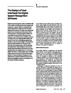
extract and retrieve requirements following several presentation styles (e.g., textual model queries, textual specifications, graphical representation). DSL has been itself derived from PSL language defined in the ISDOS/PRISE project by University of Michigan [Teichroew77]. PSL is probably one of the first pioneers in functional requirements. During the last decade, automatic generation moved from simulations and prototypes to complete UIs of interactive applications. Functional Requirements
(3)
(5)
(6)
(4)
(1) External UI Representation
(2)
Internal UI Representation
Figure 1. Possible paths for automatic generation of UIs Figure 1 illustrates six possible paths for automatically generating UIs from these types of sources (inspired from [Tarby93]): 1. Functional Requirements describe the application syntax and semantics according to a consistent formalism which can be textual or graphical or both1. These requirements generally contain requirements for data, functions, dynamics, resources, but also for a possible UI. 2. Internal UI Representation consists of pieces of code programmed in an appropriate language (e.g., Pascal, C or C++) or a higher level language (e.g., Tcl/Tk) for effectively implementing a particular UI. 3. External UI Representation refers to the graphical appearance of a UI which is visible and manipulable by users. Let us examine the six possible paths of automatic generation illustrated in figure 1 : 1. From External UI Representation to Internal UI representation : this alternative remains one of the oldest form of automatic generation, probably because it was an easy task. This path is aimed to automatically generate the UI code from its screen appearance. Designers typically edit interaction objects with a direct manipulation graphical editor ; they draw a possible UI by placing, sizing, arranging interaction objects so that they represent the different parts (i.e. the screens, the windows, the dialogue boxes) of a UI.
1
In this case, most of textual parts of the textual requirements possess a graphical counterpart.
Current Trends in Computer-Aided Design of User Interfaces
xv
This technique has been adopted by many UIMSs (e.g., UofA* [Singh91], Higgens [Hudson86, Hudson88]), toolkits (e.g., Visual User Interface Tool [DEC91]), interface builders (e.g., Trillium [Henderson90], Peridot [Myers88], Dialog Editor [Cardelli88], NeXT Interface Builder [NeXT90], and tools on top of them (e.g., JADE [vander Zanden90]). 2. From Internal UI Representation to External UI Representation. In this case, the complete graphical presentation is deduced from parts of the application code and/or parts of the UI code. This UI program code is then enhanced to become a complete one. For example, MIKE [Olsen86] and MICKEY [Olsen89] automatically generate windows consisting of labels and edit boxes for all input/output argument found in a Pascal procedure definition. CHISEL [Singh89] and SCOPE [Beshers-89] automatically create appropriate UI objects from any variable and type found in the application code. Some tools (e.g., [Shoval89, Hayhoe90]) also generate full screen menus and/or a menu bar accompanied with pull down menus according to functions belonging to the application’s functional core. Zalik [Zalik96] proposes a constraint-based system to automatically draw graphical objects from a set of rules expressed in a first-order predicate logic. This system is particularly interesting for expressing constraints on graphical objects (e.g., for drawing high-resolution fonts) and can be used to automatically place any graphical object in a container if appropriate constraints are edited. 3. From Functional Requirements to External UI Representation. This path exploits the application’s syntax and semantics to derive as automatically as possible parts or whole of a new UI. The basic idea behind this process is to reuse functional requirements that have been captured before for generating a UI, thus preserving some consistency if appropriate rules are used. A major hope behind this scene is also the ability to quickly change an existing UI when parts of functional requirements change. MECANO is particularly addressing this problem in details [Puerta94b]. This strategy is today well known as the Model-Based Approach whereas functional requirements (and sometimes other specifications) are contained in models that describe different parts of an interactive application without implementing it. Such models include [Puerta94a] : data model, domain models, user models, task models, context models, presentation models, dialogue models,..., and even a UI model. For instance, IDA required six models [Bodart89] : information structure model (by way of ERA models), function structure model, functions’ statics model, functions’ dynamics model, resources model, and data-flow model. Its successor dedicated to highly-interactive business oriented application, Tools foR an Interactive Development EnvironmeNT (TRIDENT) only considers an extended form of the information structure model (by way of object-oriented ERA models), a task model (issued from a contextual task analysis using TKS method [Johnson92c]), and an information flow model (by way of Activity Chaining Graphs) [Bodart94b, Bodart95c, Bodart95d].
xvi
Computer-Aided Design of User Interfaces The model-based approach has actively researched as we can observe many environments more or less falling in this category : ACE and Selectors [Johnson92a], ADEPT [Johnson91b, Johnson92c, Johnson95, Wilson96], AME [Märtin90, Märtin96], BOSS [Schreiber94a, Schreiber94b, Bauer96, Lonczewski96], COUSIN [Hayes85], DIANE+ [Barthet88, Tarby93, Tarby96], DIGIS [de Bruin94a], EXPOSE [Gorny94, Gorny95], FLUID [Lonczewski95a, Lonczewski95b], FUSE [Bauer96, Lonczewski96], GENIUS [Janssen93, Janssen96, Weisbecker95], HUMANOID [Szekely92, Luo93, Szekely93, Moriyón94], IDA [Reiterer95], JANUS [Balzert94, Balzert95, Balzert96], ITS [Wiecha89], KIISS [Saiz96], MACIDA [Petoud89, Petoud90], MASTERMIND [Szekely95], MECANO [Puerta94b, Puerta96a, Puerta96b], MODEST [Hinrichs96], SIROCO [Normand92], OMEGA [Metais86], PLUG-IN [Lonczewski96], TADEUS [Elwert95, Elwert96, Schlungbaum96], TRIDENT [Bodart95c, Vanderdonckt95b], UIDE [de Baar92, Foley88, Foley90, Foley94]. Most of these environments are fully described and discussed in the present volume of CADUI. Contreras & Saiz [Contreras96] highlight how one of these tools (i.e., HUMANOID [Szekely93]) can be efficiently used for automatic generation of software tutoring, proving that way that application area can be as wide as imagination.
4. From Functional Requirements to Internal UI Representation. In the previous category, we can regret that, if the External UI Representation is generated, only parts of the Internal UI Representation are generated : e.g., interaction objects definition, hierarchy of objects, skeleton of interface with application, default attributes of objects, but less code is devoted to the management of the dialogue and the UI management itself. Systems in category 3 generate working interfaces : in this way, they generate part or whole of the Internal UI Representation that drives the external one. But sometimes, they only generate the static part of the user without the connection to the application. Conversely, systems belonging to the current category generate part or whole of the Internal UI represenation : in this way, they do not necessarily encompass the external UI representation. DIGIS [de Bruin94b] and DIANE+ [Tarby96] attempt to remedy this problem by automatically introducing control structures (MVC architecture for DIGIS, OPAC objects for DIANE+). TRIDENT is limited to propose a methodological guide [Bodart95a] showing how we can map some functional specifications to blocks of programming codes that support some independence. A more sophisticated approach to deduce highly interactive dialogues from requirements is suggested in this volume by Bastide & Palanque [Bastide96] : they show how functional requirements can be efficiently expressed as Petri Nets describing dialogue structures to be implemented. 5. From External UI Representation to Functional Requirements. This path remains today unstudied not because of lack of research but probably because it seems utopian to recover requirements only from a UI [Tarby93].
Current Trends in Computer-Aided Design of User Interfaces
xvii
6. From Internal UI Representation to Functional Requirements. This novel feature is oriented towards UI reverse engineering. AUIDL is an example of trying to retrieve basic functional requirements expressed in IDL language from the UI code. From these retrieved requirements, we can re-generate a (possibly better) UI according to model-based approach, for instance. A new trend that is also appearing is the Task-Based Approach (figure 2). Rather than only working on functional requirements to generate a UI, one can start from task requirements. These requirements can typically be written by task analysts, work psychologists or ethnologists. This approach is now followed by most recent UI development environments such as, for instance, ADEPT [Wilson96], FUSE [Lonczewski96], MASTERMIND [Szekely95], MECANO [Puerta96], TADEUS [Schlungbaum96], TRIDENT [Bodart95c]. Of course, task requirements can be considered as a task model in itself (or domain model as in MECANO [Puerta96]), but, rather than using all models together for generating a UI, task requirements drive the functional requirements and can directly be incorporated for generating some parts of the External UI Representation as well as Internal UI Representation. Task Requirements
Functional Requirements
External UI Representation
Internal UI Representation
Figure 2. Task-Based Design Wilson & Johnson [Wilson96] provide an extensive set of rules for starting from task requirements. Harning [Harning96] is trying to follow the same path by introducing a structured approach for deriving External UI Representations from both Task Requirements and Functional Requirements. Several heuristics can help designers to clearly establish a transformation between them and a possible UI. In the second part of figure 2, we can see two arrows from Functional Requirements to both UI Representations since, most of the time, both representations can be generated in parallel.
xviii
Computer-Aided Design of User Interfaces
Farenc, Libérati & Barthet follow the inverse path [Farenc95, Farenc96] : their ERGOVAL tool starts from the hierarchy of interaction objects with their attribute values (External UI Representation) and from a resource file (Internal UI representation) to evaluate whether this UI matches task requirements (figure 3). Since Functional Requirements and Task requirements are not necessarily available, this task is particularly difficult to achieve and to automate. This is probably why the tool can be considered as a tool for Computer-Aided Evaluation of UIs. Comber & Maltby [Comber96] also provide techniques for rating the complexity of screens of any GUI. Rather than trying to relate this measure to Task requirements or Functional Requirements, they try to quantify the visual complexity independently. Task Requirements
Functional Requirements
External UI Representation
Internal UI Representation
Figure 3. UI evaluation A second trend that is also appearing is the notion of Computer-Aided Design of User Interfaces. In the beginning, the generation of a UI was completely automated forcing designers and developers to pick up the results of the generation and to manually tailor them according to their personal needs (i.e., Task Requirements). The problem of adapting UIs is discussed by Farhat & Fluhr [Farhat96] : not only they highlight how adapting UIs can be of high importance (especially for users with special needs) but also they emphasise the loops that can be observed on both UI Representations (figure 4).
Current Trends in Computer-Aided Design of User Interfaces
xix
Task Requirements
Functional Requirements
External UI Representation
Internal UI Representation
Figure 4. UI adapting After talking about Computer-Aided Generation of User Interfaces (CAGUI), we are today talking about Computer-Aided Design of User Interfaces (CADUI) where designers no longer remain passive. They are actively involved in the process of UI creation (which is sometimes fully automated, sometimes user-controlled, sometimes completely manual). The desire to effectively involve designers in the development life cycle is also reflected by Yamaoka [Yamaoka96] and by Copas & Edmonds [Copas96]. The first author argues that recognising the designer’s intention, one of the facets of incorporating designers during design, can be achieved through Case-Based Reasoning techniques. The second illustrates that interactive planners can clarify a declarative interaction. This book contains the results of the 2nd International Workshop on ComputerAided Design of User Interfaces held in Namur (Belgium), 5-7 June 1996. Its acronym —CADUI’96 — has been chosen to reflect the change of scope from the 1st International Workshop on Computer-Aided Generation of User Interfaces held in Ulm (Germany), 18-19 November 1993. We do hope that, in the future, tools and techniques for CADUI presented in this volume can evolve, merge and integrate to foster better UI development than ever where Designers and developers are recognised as more active persons who can see their work supported and aided by software tools; Final users are respected in the complexity of their interactive tasks.
Retrospective and Challenges for Model-Based Interface Development Pedro Szekely Abstract Research on model-based user interface development tools is about 10 years old. Many approaches and prototype systems have been investigated in universities and research laboratories around the world. This paper proposes a generic architecture for these tools, reviews the different approaches in light of this architecture, and discusses their progress towards the goals of increasing the quality and reducing the cost of developing interfaces. The paper closes with a discussion of challenges for future model-based development tools.
Keywords Model-based interface development, automatic user interface generation, user interface design.
Introduction Model-based user interface development tools trace their roots to work on user interface management systems (UIMS) done in the early 1980’s [Myers95]. UIMSs seeked to provide an alternative paradigm for constructing interfaces. Rather than programming an interface using a toolkit library, developers would write a specification of the interface in a specialised, high-level specification language. This specification would be automatically translated into an executable program, or interpreted at run-time to generate the appropriate interface. Many early UIMSs focused on dialogue specification [Green86]. They used state transition diagrams [Jacob86], grammars [Olsen83, Olsen86] or event-based representations [Singh91] to specify the interface responses to events coming from the input devices. The display aspects of the interface were typically specified outside the specification language, in call-back procedures that painted the screen as appropriate. Some UIMSs used as their main specification the type and procedure declarations that defined the functional aspects of the application [Beshers89, Olsen89]. Based on this information, they generated menus to invoke the procedures, and dialogue
xxii
Computer-Aided Design of User Interfaces
boxes to prompt users for the information needed to construct instances of the types. Through the late 1980’s and early 90’s the specification languages became more sophisticated, supporting richer and more detailed representations that allowed the systems to generate more sophisticated interfaces. Today’s systems use specifications of the tasks that users need to perform, data models that capture the structure and relationships of the information that applications manipulate, specifications of the presentation and dialogue, user models, etc. The term model-based interface development tools refers to interface construction tools that use these rich representations to provide assistance in the interface development process. Tools range from automatic interface generation systems, generators of help systems for applications, interface evaluation tools, advisors, etc. Even though model-based interface development tools are much more sophisticated than early UIMSs, they have not become popular in the commercial sector. Most software developers use interface builders, toolkits and a programming language to build the interfaces for interactive systems. The main goal of this paper is to review the current progress in model-based tools, and discuss challenges for the next generation of user interface tools in general, and model-based tools in particular. The paper is organised as follows. The next section will describe a general architecture of model-based tools that provides a way to classify model-based tools according to the components of the architecture that they emphasise. The sections after analyse the success of model-based work on automatic interface generation, high-level specification systems, help generation, and design advisors. The last part of the paper discusses new challenges for user interface software, including multi-platform support, intelligent support for the user, multi-modal interfaces and end-user tailoring. The paper closes with conclusions about the future of model-based tools.
1 Generic Model-Based Interface Development Architecture Figure 1 shows the typical components of a Model-Based Interface Development Environments (MB-IDE). The rounded rectangles represent tools, the other shapes represent information produced or consumed by the various tools. The main components of the architecture are the modelling tools, the model, the automated design tools, and the implementation tools. Developers2 use the modelling tools to build the model. The automated design tools are used to perform certain design activities that developers either choose or are forced to delegate to the system. The implementation tool 2 This paper uses the term developer to refer to all the people involved in constructing an interactive application. When appropriate, the more specific terms such as task analyst, graphic designer, programmer, etc. will be used.
Retrospective and Challenges for Model-Based Interface Development
xxiii
Model Task, Domain Models Modeling Tools Modeling Tool Modeling Tool
Abstract UI Specification
Automated Design Abstract Design Tool
Design Knowledge
Concrete Design Tool
Guidelines
Concrete UI Specification Implementation Tool
Developer
Design Critics Design Advisors
Toolkit-Ready File
Application Code
Compiler/ Linker
Runtime System
Delivered Application
Figure 1. Model-Based Interface Development Process transforms the model into an executable representation that is linked with application code, and delivered to the end-users. The following subsections discuss these components in more detail. 1.1 Model The model is the main component of the system. The model typically organises information into three levels of abstraction. At the highest level are the task and domain model for the application. The task model represents the tasks that users need to perform with the application, and the domain model represents the data and operations that the application supports. Tasks models typically represent tasks by hierarchically decomposing each task into sub-tasks (steps), until the leaf tasks represent operations supplied by the application. The second level of the model, called in this paper the abstract user interface specification, represents the structure and content of the interface in terms of two abstractions, Abstract Interaction Objects (AIO), information elements and presentation units. AIOs are lowlevel interface tasks such as selecting one element from a set, or showing a presentation unit. Information elements represent data to be shown, either a constant value such as a label, or a set of objects and attributes drawn from the domain model. Presentation units are an abstraction of windows. They specify a collection of AIOs and information elements that should be presented to users as a unit. In summary,
xxiv
Computer-Aided Design of User Interfaces
the abstract user interface specification specifies in an abstract way the information that will be shown in each window, and the dialogue to interact with the information. The third level of the model, called the concrete user interface specification, specifies the style for rendering the presentation units, and the AIOs and information elements they contain. The concrete specification represents the interface in terms of toolkit primitives such as windows, buttons, menus, check-boxes, radio-buttons, and graphical primitives such as lines, images, text, etc. In addition, the concrete specification specifies the layout of all the elements of a window. The models of different MB-IDEs can differ substantially. Different MB-IDEs typically provide different modelling languages for specifying the contents of the model, and they also emphasise different levels of the model. For example, MASTERMIND [Szekely95] requires developers to explicitly specify all levels of the model, whereas JANUS [Balzert96] only requires a data model. 1.2 Modelling Tools The modelling tools assist developers in building the models. The main goal of the modelling tools is to hide from developers the syntax of the modelling languages, and provide a convenient interface for developers to specify the often large quantities of information that are stored in the model. A wide range of modelling tools have been developed, often specialised to the different levels of the model. These tools range from text editors to build textual specifications of models (ITS [Wiecha89, Wiecha90], MASTERMIND), forms-based tools to create and edit model elements (MECANO [Puerta96b]) and specialised graphical editors (HUMANOID [Luo93, Szekely92, Szekely93], FUSE [Lonczewski96], many others). 1.3 Design Critics and Advisors Design critics are tools to evaluate designs. The model-based approach provides an excellent platform for constructing analytic design critics because models contain a rich representation of interface designs that these tools can analyse. Most design critics work with the concrete user interface specification layer of the model because in most cases they provide evaluations about detailed features of the interface (e.g., whether the interface provides a way to access all application functionality). Design advisors are tools that suggest how to refine the abstract layers of the model into more concrete ones. Design advisors use a knowledge-base of design knowledge, typically represented as rules. The condition part of the rules identifies some aspect of a design (e.g., an AIO), and the action part of the rule specifies a way of refining/transforming the matched design element (e.g., the CIO to use for an AIO). 1.4 Automated Design Tools Many MB-IDEs allow developers to only specify certain aspects of a model. These MB-IDEs feature automated design tools that compute the missing elements of the
Retrospective and Challenges for Model-Based Interface Development
xxv
model from the information that developers do provide. For example, JANUS [Balzert96] only requires developers to supply a domain model, and it features an automated design tool that automatically constructs both the abstract and concrete specifications of the interface. In contrast ITS and MASTERMIND [Szekely95] require developers to explicitly specify all levels of the model, so these systems do not offer automated design tools. What they do offer is the capability to re-use specifications. The following section discusses automated design tools in detail. As shown in figure 1, automated design tools often use a repository of design knowledge or design guidelines that control the behaviour of the design tool. In most systems developers are not expected to modify the design knowledge, which is typically specified by user interface specialists and the architects of the MB-IDE3. 1.5 Implementation Tools The implementation tool translates the concrete specification of the interface into a representation that can be used directly by a toolkit or interface builder. There are essentially three kinds of implementation tools. Source-code generators (e.g., Mastermind) generate source code in a programming language, typically C++. UIMS generators (e.g., FUSE) generate a file that can be read by an existing UIMS or interface builder. Interpreters (e.g., ITS and HUMANOID) do not generate an “implementation file”, but rather interpret the model directly at runtime. The last step in the interface generation process is to link the toolkit-ready-file with application specific code and a runtime library. This is typically done using the compiler and linker for the programming language used to implement the application. Interpreter-based systems such as ITS do not use the compiler and linker, but rather feature a runtime module that reads the models during runtime, and interprets the concrete specification of the interface. Many MB-IDEs provide implementation tools that use the model to generate more than the user interface. For example, JANUS, FUSE, UIDE [Foley91, Foley94] and HUMANOID can generate significant parts of the help system for an application based on the information contained in the model. Janus not only generates the interface, but also generates the database schemas for an application, and much of the data management code. Mastermind generates code for applications that allows other processes to connect to an application, and to request to be notified when certain tasks are completed, to be sent snapshots of the application state, and to remotely invoke application tasks. This facility supports the construction of agents that can assist users in various ways. This facility was used, for example, to build a history agent that keeps a history of all the tasks that the user has completed an allows users to re-invoke previously completed tasks. ITS can be viewed as an automated design tool where developers have to explicitly build the design knowledge for each application or family of applications.
3
xxvi
Computer-Aided Design of User Interfaces
As interfaces become more sophisticated, and users expect more services from their interfaces. The ability to provide such additional run-time services for free is one of the most attractive features of the model-based technology.
2 Retrospective The following sections provide a retrospective of the main user interface design and construction problems that have been addressed using the model-based approach. These sections discuss the various approaches that have been used, and how well they solve the problems. The retrospective section is organised into five main topics: 1. Automatic interface design. This section discusses the main approaches for automating interface design and their limitations. 2. Specification-based MB-IDEs. This section discusses MB-IDEs that do not try to automate interface design, but rather give developers convenient languages for expressing designs. 3. Help generation. Many MB-IDEs feature components that automatically generate help. This section reviews the different approaches and comments on their success. 4. Modelling Tools. This section discusses various approaches to modelling tools. 5. Design critics and advisors. This section presents a categorisation of these tools and discusses their relative benefits. Note. For each topic one or two tools are discussed in some detail. The chosen tools are not necessarily the best tools according to some metric, but rather illustrate a point well, and detailed papers have been published about them. The goal of this paper is to review the main approaches, not the individual tools. 2.1 Retrospective – Automatic Interface Design The primary goal of many MB-IDEs is to automate as much as possible the design and implementation of a user interface. These MB-IDEs emphasise the domain and task models, and automatically generate the abstract and concrete user interface specifications from these models. Most MB-IDE in this category are oriented towards database applications and produce interfaces that allow the end-users to browse the database, to edit the contents of objects, to define new objects, and to delete objects. This section argues that automating interface design is intrinsically difficult, so MBIDEs should be very selective about the portions of the design that they choose to automate. 2.1.1 Structure of Automated Design Tools Model Contents. MB-IDEs whose primary goal is to automatically design use mainly two kinds of models, a domain model that describes the structure and attributes
Retrospective and Challenges for Model-Based Interface Development
xxvii
of the information that the application provides, and a task model that describes the tasks that users need to perform. For example, tools like JANUS, and early versions of MECANO, use only a domain model, whereas tools like TRIDENT [Vanderdonckt94a, Vanderdonckt95b], ADEPT [Johnson95, Wilson96], DON [Kim 93] and MODEST [Hinrichs96] use primarily a task model, but also have a domain model. The domain models of the automatic design tools are similar. They describe classes of objects, inheritance between classes, the attributes of each class together with their types and cardinality, and relationships between objects. In addition, the models typically allow the inclusion of user interface specific information. For example the model of object attributes often includes facets to indicate whether the attribute should be shown to the user, an ergonomic name, and other information to influence the choice of abstract interaction object to be used to specify the attribute. The task models of these tools are also similar. Tasks are usually decomposed hierarchically, and information is included to specify the sequencing between the tasks (e.g., and, or, xor, parallel). Often, the task model includes references to the domain objects needed and produced in each task. The task model is used during automatic generation to determine the interface dialogue and to determine the information that should be shown in each window. MB-IDEs in this category typically do not require developers to specify either the abstract or concrete specifications of the interface. Design Process. Most automated design MB-IDEs use the following sequence of steps to automatically design an interface: 1. Determine the presentation units. This step essentially determines the windows that will be used, and what information will be shown in each window. 2. Determine the navigation between presentation units. This step computes a graph of presentation units that defines which units can be invoked from which other units. 3. Determine the AIOs for each presentation unit. The abstract interaction objects specify the behaviour of each element of a presentation unit in an abstract way (e.g., select one from set). 4. Map abstract interaction objects into concrete interaction objects. The concrete interaction objects represent the widgets available in the target toolkit. 5. Determine the window layout. This steps determines the size and position of each concrete interaction object. The first three steps build the abstract user interface specification, and the last two build the concrete specification. Post Editing. Once the concrete specification is built, and the implementation tool generates the “toolkit-ready” file, the developer has the opportunity to use and interface builder beautify the layout, change fonts, colours, add decorations, and perform other cosmetic enhancements.
xxviii
Computer-Aided Design of User Interfaces
2.1.2 Difficulties with Automated Design Even though automatic design MB-IDEs can produce interfaces with little or no development effort, there is concern about the quality of the generated interfaces. There is substantial evidence to indicate that it is not feasible to produce good quality interfaces for even moderately complex applications from just a data and task models (together with simple annotations of the data model, such as flags that indicate whether object attributes are relevant to the user interface). The chapters by Morten Harning [Harning96] and by Stephanie Wilson and Peter Johnson [Wilson96] describe critical decisions that must be made in the design of an interface, which the automated design tools cannot currently make appropriately, and which do not seem feasible to automate. Harning’s paper contains an excellent example that illustrates the difficulty of automating steps 1 and 3. Harning’s example is about a project management application where users want an interface to monitor progress in the various activities involved in a project. In this application there are four classes of objects represented in the data model: Employee, Project, Activity, Weekly Estimate, and Time Entry. Harning demonstrates using examples that of a good interface must satisfy the following properties:
Users need windows that show information drawn from multiple objects. In the project monitoring example, the project display is based mostly on the Project object, but also shows attributes of the Employee and Activity objects. Furthermore, the example shows that the choice of attributes is task-dependent, and required developers to have a deep understanding of the user’s tasks. This means that step 1 of the abstract design tool is hard, if not impossible to automate. This property is achieved in the interfaces generated using Trident. The Trident task model captures the information needed for each task, and the generation algorithm calculates how the information flows between tasks in order to determine what information to show in each presentation unit, and where to place it. Systems like Janus, which only use the data model do not satisfy this property.
Users do not want the raw information, but rather they need the information to be re-structured and summarised. In the project monitoring example, users want a weekly report display that essentially combines the Activity and Weekly Estimate objects on a weekly calendar display that shows how much effort was spent on each activity during a specific week. Re-structuring and summarisation cannot be done without a deep understanding of the user’s tasks, and again points to the difficulty of automating step 1. Another restructuring problem is that users want to see the names of people in the Project Leader field as “name (initials)”. This means that rather than using two AIOs to present two different attributes, a single one should be used to present a combination of two attributes. This simple example suggests that the assignment of object attributes to AIOs (step 3) is also a hard problem.
Retrospective and Challenges for Model-Based Interface Development
xxix
Graphical displays are often more effective than tables and forms. Harning’s paper has an example of a graphical display that uses a plot with two curves to show how much time has cumulatively been spent on a project compared to the estimate of the time remaining to complete the project. This example shows that the set of AIOs need to be expanded to include more sophisticated elements such as plots. Of course, then the problem is how to select the appropriate one (step 3), how to set all its parameters, and then how to map it to concrete interaction objects (step 4).
There are two main approaches to automatic design, one based on task models, and the other based on the domain model. The task model approach performs better because task models have some of the information to satisfy the properties listed above. The domain model approach does not have access to such information, and can only produce simple interfaces, typically with one object per presentation unit. The requirements listed above point to deep issues of interface design, and raise questions about the utility of completely automating the design process, especially steps 1 and 3. Even a small amount of developer involvement can have a huge difference. A simple calculation reveals the economics of the situation. Most of the automatically designed interface force users to bring up several windows to view the information they need to perform a task, rather than a single window with all the information. Ignoring issues about time to assimilate improperly structured information and the error rates that can result, bringing up several windows and closing them can easily take 3 additional seconds. If users do this 20 times a day, in a year, one full day will be lost per worker. If an organisation has 40 users, 2 man months will be lost per year. Surely it is worth to have developers spend several weeks working on a design. 2.1.3 Discussion The conclusion of this section is that none of the 5 steps should be completely automated. Rather, collaboration between developers and tools should be built in from the start. Tools should offer suggestions and alternatives. Developers make the decisions, accepting suggestions, choosing between alternatives or entering their own solutions. This means that the abstract and concrete specification layers of the models should be available to the developers. The specification languages for these layers must allow developers to control all features of the interface that they want to control, no matter how low level. Emphasis should shift from automation to computer aided design. A simple, and commonly used approach to computerised design aids is the postediting approach. An automated generation tool generates a first draft of the design, and then the developer edits the draft to produce the final design. This approach has a serious shortcoming, namely that when developers change the model, they need to run the generator tool again, and the post-editing changes will be lost.
xxx
Computer-Aided Design of User Interfaces
The post-editing approach has been used mainly to allow developers to beautify layouts. However, many MB-IDEs such as FUSE feature automatic generator of higher levels of abstraction, and run the risk of running into the same post-editor problems. One solution to the post-editing problem is to record the changes performed during post-editing, and to reapply them to the output of the generation tools. This approach was used in early versions of MECANO, but it proved difficult to apply the changes reliably, especially when new elements were introduced to a design, or old elements were deleted. A more robust solution requires a deep integration of the computerised advisor and the modelling tools. In this approach the advisor tools produce design alternatives and suggestions that developers can incorporate into an evolving design via the modelling tools. There is no batch generation process followed by a refinement phase, but rather an incremental evolution of the design, where the computerised advisors and the developers incrementally build the design. Several MB-IDEs are moving away from automation in the direction of computerised advisors. For example, the TADEUS [Elwert95, Schlungbaum96] system requires developers to specify steps 1 and 2 in a structure called a dialogue graph. Steps 3 and 4 are table driven. The system builds default tables with default entries, but developers can edit these tables and override any entry. Step 5 is done automatically, but TADEUS supports post-editing of the generated implementation file. The FUSE system described in this book also provides a specification language and tool (BOSS [Schreiber94b]) that lets developers specify the abstract interface specification, and many aspects of the concrete specification. In addition, FUSE provides a tool (FLUID [Bauer96]) that uses the task and domain model to produce specifications that can be fed to the BOSS tool to refine and produce an interface. It is unclear for the published papers whether and how FUSE avoids the post-editing problem. TRIDENT is perhaps the most sophisticated and robust system that combines automatic generation and computerised advice. TRIDENT developed many different strategies and algorithms for performing each of the 5 steps listed above. For example, they developed six strategies for defining presentation units, and have tools that can automatically select and apply a strategy based on information contained in the task and domain model. TRIDENT also offers developers the option of choosing a strategy, or performing the step by hand. However, it is unclear from the published literature on TRIDENT whether it uses an integrated approach as described above. 2.2 Retrospective – Specification-Based MB-IDEs MB-IDEs in this category seek to provide powerful interface specification languages. These languages provide effective layering or abstraction mechanisms that allow developers to express interface properties at a convenient level of abstraction to facilitate reuse and design modifiability. These languages also seek to give developers extensive control over all features of the interface, so that developers can express
Retrospective and Challenges for Model-Based Interface Development
xxxi
any design that they can think of. The goal is not to automate design, but rather to make it easy for developers to express designs, change designs, retarget designs to new platforms, new classes of users, new tasks, etc. MB-IDEs in this category are oriented towards data management applications. Most business-oriented applications fall in this category, but many engineering and data visualisation applications do not, because they have interfaces whose graphical components are too complex to be expressed in their interface specification languages. 2.2.1 Structure of Specification-Based MB-IDEs The structure of specification-based MB-IDEs is also compatible with the architecture shown in figure 1. They emphasise the model and the implementation tool, and typically do not have an automated design tool. The modelling language of these MB-IDEs have facilities for developers to express models at the three different levels of abstraction shown in figure 1. The models of these MB-IDEs typically feature a data model, but not always a task model. The data model is used mostly in the implementation tool to generate the binding between the interface objects and the application data, so that the interface objects can access the application objects to retrieve the pieces of information that will be displayed (e.g., access the name field of a person object). The modelling languages to specify the abstract and concrete user interface specifications are designed to maximise reuse. Even though the goals of the different MBIDEs in this category are the same, the features of the modelling languages are different. For this reason, this section will not attempt to describe these languages in general terms, but rather uses the well known ITS system as an example. Other MBIDEs in this category include BOSS, HUMANOID and MASTERMIND. 2.2.2 ITS The ITS system was developed by IBM research, and was used to construct several large applications such as the information kiosks for the Seville world fair, a purchasing system for a large corporation, an insurance industry application, and many others. ITS has modelling components corresponding to the three levels of modelling shown in figure 1. The domain model is called a data pool, there is no task model, the abstract specification is called content specification, and the concrete specification is called a style specification. The data pool definition language (domain model) supports the specification of structured objects and sequences of objects, like the domain model in many other MB-IDEs. The following is an example of the data pool specification for an airline reservation system.
xxxii
Computer-Aided Design of User Interfaces list listname = flights, numrecords = 10 field destination, rangename = cities, size = 20 field departure_time, size = 10 field departure_date, size = 20 field airline, rangename = airlines, size = 20 field number_stops, size = 5
The content specification (abstract user interface specification) of an interface consists of a collection of frames. Frames can contain lists, forms, choices, information blocks, and nested frames. These elements specify the information that will be presented to the user. Top-level frames correspond to presentation units. Lists and forms specify which elements of the data pool are to be shown in a frame. Information blocks specify static pieces of information to be shown in a frame. Choices indicate sets of alternatives that can be chosen by the user, and correspond to AIOs. Each element specification can be elaborated using an extensive set of attributes that specify the interface content in detail. The following is a fragment of the content specification for the airline reservation example. This frame specifies that five flights are to be displayed, and specifies which fields of the flights object to display. frame id = check_today, action = getlist, listname = flights, value = flights.data list listname = flights, number = 5 list-item field = destination, message = “To” list-item field = departure_time, message = “Departure” list-item field = departure_date, size = 20 list-item field = airline, message = “Carrier” frame message = “To search for selected flights” ...
The style specification (concrete user interface specification) specifies the mapping from AIOs to CIOs. To quote from Wiecha’s paper, “a style is a co-ordinated set of decisions on the appearance and behaviour of the interaction techniques used in a family of applications”. Styles are specified using rules. The condition part of the rule can test any of the attributes of a frame or its children. The action part of the rule selects the CIO to use, and specifies values for the attributes. Typically, the rule set for an application consists of general rules that apply to families of frames (e.g., there could be a rule for displaying choices as radio buttons), and specific rules that match specific frames defined in the content (e.g., a rule for the check_ today frame defined above). General rules are reused in multiple applications and within a single application. Specific rules are used to specify the features of a particular interface that make it different from the generic case. The following is an example of a style rule. It specifies that if the content is a choice, then construct a vertical group of a title, and something else, depending on which of the nested conditions match. If only one element can be chosen, then the second component is a vertical group, or a collection of horizontal groups, one for every choice. The horizontal group consists of a dingbat to indicate radio buttons, and a message. Note that this rule does not completely specify the display of choices.
Retrospective and Challenges for Model-Based Interface Development
xxxiii
Other rules may be used to determine the attributes of the unit types used within this rule (VertGroup, HorzGroup, Dingbat and Message). :conditions source = choice unit type = VertGroup unit type = Title :eunit :conditions kind = 1_and_only_1 unit type = VertGroup unit type = HorzGroup, replicate = all unit type = Dingbat :eunit :unit type = Message :eunit :eunit :eunit :econditions … … :eunit :econditions
The implementation tool of ITS consists of the rule interpreter and the run-time support system that fires the rules appropriate rules when actions are invoked and the contents of the data pool change. 2.2.3 Discussion The main difference between specification-based systems such as ITS, and automated design tools such as JANUS is one of philosophy. In specification-based MBIDEs the modelling language is open, whereas in automated design tools it is closed. In automated design tools, developers can only control the design using a few attributes that the tool developers chose to export for that purpose, limiting the developers’ ability to control the design of interfaces, and ultimately limiting the quality of the interfaces that can be generated. Even though ITS is a specification-based MB-IDE, developers do not specify all the features of every individual window. The main point of ITS is that developers should not have to do that. Developers using ITS must specify the abstract user interface specification completely, that is, they have to specify the abstract interface for every different kind of window. As argued in the previous section, this is good because the abstract interface is precisely the hardest aspect to generate automatically. However, developers using ITS do not have to specify the concrete user interface specification completely. There is no automated designer to do it, but developers can reuse rule sets from libraries that contain the abstract to concrete mapping for significant portions of the interface specification. This reuse capability enables specification-based MB-IDEs to incorporate many of the cost savings capabilities of automated designers, while overcoming the most serious problems. Other specification-based MB-IDEs such as HUMANOID and MASTERMIND share the design philosophy of ITS, but differ in the nature of the modelling language. In
xxxiv
Computer-Aided Design of User Interfaces
a large logistics application developed using HUMANOID, the developers were able to identify about 13 different families of windows to account for the more than 100 different windows that the system provided. Developers modelled those 13 windows so they did not have to specify each window separately, as would appear to be necessary with a pure specification-based system. However, the design of the 13 windows was according to user requirements, and it would not have been possible to design those windows automatically. The BOSS system, briefly described in Lonczewski’s and Schreiber’s chapter [Lonczewski96], is another example of a specification-based MB-IDE. BOSS is also a module of the FUSE system, which is a mixture between automated designer, as implemented in its FLUID module, and a specification system. 2.3 Retrospective – Help Generation Many MB-IDEs [Lonczewski96, Moriyon94, Pangoli95, Palanque93b, Sukaviriya 90] have the ability to automatically, or semi-automatically generate a help system for an application based on model information used to construct the user interface in the first place. Cartoonist [Sukaviriya90] was the first system to provide a compelling demonstration of help generation. Cartoonist allowed the user to ask “how do I do X?” questions, where X could be any of the actions of an application. In response, it would show an animation showing the exact actions that the user needed to perform with the mouse and keyboard to invoke the action. A typical example would show the mouse selecting an object (if one was not selected), then pulling down the appropriate menu, filling out a dialogue box, and finally clicking the OK button. Cartoonist used the UIDE interface models. The abstract interface specification of UIDE describes the actions that users can perform. The action specification contains pre-conditions that specify the contexts in which the action can be performed, and post-conditions that specify how actions modify the context. The concrete specification models the mapping between actions and concrete interaction objects. Using this information, Cartoonist was able to construct a plan with the sequence of interaction techniques that needed to be invoked in order to perform an action. Cartoonist could even determine what other actions need to be invoked before in order to modify the context to satisfy the preconditions of the action being explained. This allowed the user to ask for help at any time, even when the context was not appropriate to perform the action. HUMANOID also generated a help system for an application based on the model [Moriyon94]. The help system provided hypertext help to explain the information displayed in a region selected by the user (e.g., paper.txt represents a file), and explain all the commands that the user could issue (e.g., paper.txt can be selected by clicking with the left button, and then the commands delete, and grep can be applied to it). An important contribution of the HUMANOID help system is that it used an example-based technique to assist developers in specifying the text of the help windows.
Retrospective and Challenges for Model-Based Interface Development
xxxv
HUMANOID first generated text automatically, but developers could select text fragments to edit the wording, and then HUMANOID would interact with the developer to find an appropriate place in the model to store the edited text fragment. Placement in the model determined the contexts in which the text fragment would appear. The chapter by Contreras and Saiz in this book [Contreras96b] illustrates how the knowledge in the models can be used to automatically generate software tutors, and how the tutors can be customised to different classes of users with different tutoring needs and preferences. The chapter on the FUSE system, also describes how the information in a model can be used to construct a help system. FUSE, like Cartoonist, produces context sensitive help using the model information. It uses a different style of modelling and also delivers the help in HTML pages rather than using animation. 2.3.1 Discussion The ability to generate help systems using the information contained in the model is one of the main benefits of the model-based technology. All of today’s applications feature a help system, and significant development effort must be devoted towards implementing it. Context-sensitive help is especially difficult to implement because it must reference internal data structures of the interface in order to query the current context of the interface. The next sections argue that it is precisely the ability to generate runtime services such as help, that give the model-based technology an edge over conventional technologies for implementing interfaces. Using conventional technologies, each runtime service must be separately designed and implemented. Using the modelbased technology the services are generated for free, or for a small incremental cost. The reason is that the services use the same information that is used to build the interface in the first place. In addition, as an interface design evolves, the services automatically evolve with it to remain consistent with the design. 2.4 Retrospective – Modelling Tools Interestingly, ITS, the most widely used MB-IDE does not have a graphical modelling tool. Developers must learn the syntax of the modelling language, and enter the models using a text editor. The creators of ITS found that developers learn the syntax of the language quickly, and that the lack of a modelling tool is not an obstacle to using the tool. They also report (personal communication) that a syntax directed editor was built, but developers refused to use it. The lesson to be learnt from this experience is that it is false that some tool is better than no tool. A text editor is a powerful tool that is always available. Its most attractive features are users know how to navigate with it, that it is very fast, that it provides cut and paste, effective search mechanisms, global replace, the ability to easily comment out pieces of a design, etc.
xxxvi
Computer-Aided Design of User Interfaces
However, experience with widely used CASE tools, and expert system shells such as Nexpert Object [Nexpert96] and Kappa [Kappa96] suggest that well engineered graphical tools for building models are useful for the development of large applications. They can be better than text editors, but they must be well engineered, and designed to support large applications. Most MB-IDEs feature simple forms-based interfaces for creating and editing model entities. Some MB-IDEs such as FUSE and ADEPT provide visual modelling tools. These tools have not been extensively used, so it is early to comment about their usability for developing large applications. An interesting approach to modelling tools is embodied in a tool called Grizzly Bear [Frank95]. This tool tries to hide from developers the intricacies of the models by providing an interface that looks like a traditional interface builder or a drawing editor. The interface provides a palette of building blocks and a drawing area where developers can draw pictures of the interface. Grizzly Bear builds models by demonstration. It extracts model entities from the example interfaces that developers draw. It can generalise different pictures into different classes, and most importantly, it can infer dialogue fragments from before and after snapshots of an interface. Grizzly Bear was used to completely build the model for a simple drawing editor based on demonstrations of how the editor should work. An interesting feature of this tool is that it shows developers a textual view of the model as it is being constructed. This view helps novice developers learn the modelling language, and allows experienced developers to edit the textual representation directly. Grizzly Bear represents the first step towards this kind of tool, and further progress needs to be made before such a tool is ready for serious application development. 2.5 Retrospective – Design Critics and Advisors Much work on design critics and advisors has been done in the context of modelbased tools [Bodart95d, Fischer93]. The reason is that in order to evaluate a design, and automated critic has first to analyse the design to determine what it does. The models provide rich information for critics and advisors to do their work. The following kinds of evaluation tools have been investigated. Property verification. The tool verifies that a design satisfies certain properties (e.g., all application functionality is reachable). Some tools [Foley94, Palanque95] can only verify a set of pre-defined properties encoded in a knowledge-base. More powerful tools [Paternó96] allow developers to specify the properties to be verified. End-user simulation. These tools [Kieras96] simulate a user interacting with an application, and make predictions about times to perform tasks, learning times and likely errors. Summative evaluation. These tools produce numbers that can be used to rank designs. An example of such a tool is AIDE [Sears95], a tool to compute metrics based on a theory of layout quality. Work on such tools is still very preliminary. The chapter by
Retrospective and Challenges for Model-Based Interface Development
xxxvii
Comber and Maltby [Comber96], in this book describes experiments designed to validate the results of some of these tools. Many property verification tools [Löwgren92] are designed to detect violations of standard user interface guidelines (e.g., File menu should have the mnemonic F). These tools play a similar role to spelling checkers in word processors: they detect surface problems that show a lack of professionalism. They do not detect problems related to the semantics of the interface, but nevertheless, they are very useful. Most style-guide verification tools are not model-based, but rather take as input the toolkit ready file used in well known toolkits (e.g., resource files for Windows, UIL files for Motif). The limitations of these tools are discussed in the paper by Farenc et. al. in this book [Farenc96]. The problem is that the toolkit-ready file does not contain enough information about a design to verify many of the style rules. In the context of ERGOVAL, 44% of the rules can be automatically verified using the toolkit-ready file, and up to 78% could be automated if the evaluation tool had access to appropriate information. The model-based approach to interface development should allow tools to get closer to the 78% limit. For example, Farenc et. al. illustrate the limitations of toolkit-ready files with the rule that states that “for any input, if there are any acceptable values, such values must be displayed.”. Such a rule can be automated in the context of most MB-IDEs because their models contain information about the acceptable values for inputs, and information about how the inputs are displayed. There are a few notable examples of design critics aimed at more fundamental design issues, addressing issues similar to grammar and document content in word processing. These critics require very detailed models, more detailed than the models currently being used in most MB-IDEs. One example of such a tool is NGOMSEL [Kieras96], which belongs to the end-user simulation category of design critics. NGOMSEL takes as input a detailed task model where the leaf tasks represent interaction techniques (CIO). It can simulate a user interacting with the application, and predict how long it will take an expert user to complete a high level task. NGOMSEL can also make predictions about features of an interface that users will find difficult to learn. Another example of a sophisticated design critic is embodied in the work of Fabio Paternó [Paternó95]. His critic is a property verification critic that uses detailed models of an application specified using the LOTOS [Paternó92] notation. His system allows developers to specify complex properties using a notation based on temporal logic. One of Paternó’s papers [Paternó95] discusses an interesting example about an air traffic controller application that uses a message area to display messages to the user. The last message to arrive is shown in the message area, and the previous ones are queued until the operator gets around to view them. This design could lead to subtle timing problems where operators delete the wrong message, skip viewing a message, etc. His paper shows how required properties of this interface can be verified (e.g.,
xxxviii
Computer-Aided Design of User Interfaces
the user can read a message several times), or how undesirable effects can occur (e.g., user unwittingly deletes the wrong message). The expense of building the complex models required by this critic can be justified in safety critical applications such as air-traffic control. Much work remains to be done before these advanced critics become a useful tool for developers. These critics require detailed models that are time-consuming to build, and expressed in specialised notations that most developers do not know. However, work is in progress to integrate these tools with MB-IDEs (NGOMSEL with MASTERMIND [Byrne94], Paterno is working on an implementation tool for his notation). Once this work is complete these design critics will have a more substantial impact on the design and development of interfaces. An interesting question is the extent to which MB-IDEs can render style-guide verification tools unnecessary because the kinds of errors that they detect cannot be committed when using an MB-IDE. Automatic generation MB-IDEs provide one answer to this question. The design algorithms of these tools are based on style-guides, so they will automatically be obeyed. Most violations will be due to exceptions specifically coded in the design algorithms. Design advisors provide a different answer to this question, in the context of specification-based MB-IDEs. Design advisors can be viewed as pro-active critics. Rather than telling designers what they did wrong, they try to steer designers away from poor design choices. The most attractive feature of automated design advisors is that they complement specification-based MB-IDEs so that developers do not have to construct specifications on their own, but are assisted by advisors whose knowledgebases codify expert knowledge and wisdom about interface design. The work on design advisors has not yet reached a level of maturity that allows a critical discussion of their approach and effectiveness. Two well known systems are TRIDENT [Vanderdonckt95b] and EXPOSE [Gorny95].
3 Challenges and Opportunities The main opportunities for model-based interface technology lie ahead because it is better suited than traditional technology to meet the new interface challenges that technology is creating. Faster machines and networks enable more an more sophisticated applications, providing users with more capabilities and more information, but at the same time overwhelming them with more commands and options. Interfaces will need to become more intelligent to assist users in performing their tasks, to help them come up to speed in a new application, to allow users to customise them to make them effective for the particular tasks that users perform most often. Laptops are commonplace. Smaller portable devices such as PDAs and pagers are getting linked to the networks and provide the ability to access the same information
Retrospective and Challenges for Model-Based Interface Development
xxxix
that is available via workstations and laptops. The need will arise for applications that scale across a wide range of devices to provide users with the same or a scaled down version of the workstation functionality. Scaled up versions will also be needed to take advantage of wall-sized displays. New modalities such as speech, natural language, hand-writing recognition are maturing. Applications will need to reconfigure their interfaces to take advantage of whatever modalities are available on the user’s platform. The following sections discuss why the model-based technology is well positioned to meet these challenges, and give some suggestions on how MB-IDEs need to evolve. 3.1 Challenge 1 – Task-Centred Interfaces The main difficulty that users face when interacting with an application is to figure out how to use the capabilities of the application to perform desired tasks. Applications often offer many dozens of commands and options, so it is difficult for users to learn and remember the sequence of commands needed to perform a task. Many of the most popular and complex applications such as Microsoft Office and its competitors attempt to cope with this problem by offering task assistants. For example, Microsoft Excel has assistants to construct charts, to pivot tables, to create templates, etc. Microsoft Word has assistants to format tables, to format documents, to correct spelling, to do mail merge, etc. The typical behaviour of an assistant is to analyse the current context (e.g., the array of selected cells in a spreadsheet), and then ask users a sequence of questions about how they want the task performed, and finally perform the task for the user. Assistants make certain tasks easy to perform, even if the limit the set of options that users have. Related to task assistants are guidance systems. Guidance systems have two main components, an indexing component that helps users find the topic they need guidance on, and a component that component that guides the user in performing the task. For example, Microsoft’s answer wizard, a kind of guidance system, allows users to index in several ways: they can use keywords to find topics, of they can browse the hierarchy of topics. Guidance is given to users using the task assistant technology, traditional hypertext help windows, enhanced hypertext windows with buttons to invoke relevant application functionality. Today’s task assistants and guidance systems are implemented separately from the interface, most surely at a significant development cost. Developers of these systems must, at least informally, build a model of the tasks that users are expected to perform. For the task assistants they must encode in detail all the steps for performing the task, taking into account all the contingencies that arise from the different contexts in which the assistant is invoked. For the guidance systems, developers must encode a comprehensive model of the tasks, including the words that can be used to index them, the steps for each task, pointers to application commands that perform particular steps, etc.
xl
Computer-Aided Design of User Interfaces
One of the challenges and opportunities for model-based technology is to partially automate the generation of task assistants and guidance systems. Many MB-IDEs use a task model to assist with the design of the interface, and also to control the dialogue at runtime. Such task models already contain much of the information needed for task assistants and guidance systems. They already contain a representation of all the tasks, the steps to perform each task, sequencing constraints, information needed for each task, etc. The abstract and concrete interface representation contain the information that links tasks to the interaction techniques that invoke the various steps of a task. It seems quite sensible to enhance the task model representation to include any additional information needed for the task assistants and guidance systems, and to generate these services from the model. As mentioned in a previous section, significant progress has been made in this direction. What is needed is to make the transition from an interesting feasibility demonstration, to a robust, high quality implementation. Current demonstrations of help generation work for some of the tasks, not all, generate poor quality text full of the internal names of objects (e.g., start1stConnection), and for the most part, have never been user tested or formally evaluated. The comparison between automated design tools and specification-based tools is relevant here. Automatic interface generation systems offer interesting demonstrations, but only systems like ITS become successful, because they provide developers with appropriate control over the design. Likewise, model-generated task assistants and help generation systems will achieve high enough quality only if developers of these systems can exert complete control over the text that is produced, and significant control over the format. 3.2 Challenge 2 – Multi-Platform Support Most of the user interface tools developed during the late 1980’s and early 90’s were designed for a canonical platform featuring a mouse, a keyboard, and a 13 inch colour monitor. Today’s platforms are stretching the limits of the canonical platform, often yielding hard to use interfaces. Large, high resolution monitors cause the displays of some applications to become unusable because the icons and text become hard to see, and hard to point at with the mouse. Smaller displays, such as laptop 9 inch displays result in some applications using almost all the screen space for menus, toolbars, dialogue boxes, leaving users a tiny window to perform their work. As argued before, the situation will get much worse once radically smaller (PDA, pager) and larger devices become popular (wall displays). Interfaces developed using traditional interface builders and toolkits are hard to adapt to different platforms because developers must redesign each window for each new platform. As the set of platforms proliferates, this becomes expensive. Model-based technology offers a much better approach. For qualitatively similar devices (e.g., workstation and laptop), changes in the AIO to CIO mapping, and the
Retrospective and Challenges for Model-Based Interface Development
xli
CIO parameters are typically enough to appropriately scale the interface. More radical changes can be done by redesigning the abstract interface specifications. The important point to bear in mind is that in a system like ITS the amount of work is proportional to the number of style rules, which is typically much smaller than the number of windows. ITS has demonstrated the usefulness of this approach by refining style rules to port interfaces to use a touch screen rather than a mouse. The change involves making the target areas larger, and increasing the spacing between adjacent target areas. One of the interesting challenges in this area is to develop techniques to scale interfaces to radically different platforms, such as PDAs and pagers. Figure 2 shows an example of a first step in this direction. The figure shows simple adaptations explicitly represented in Mastermind’s model that cause an interface to adapt to changes in screen size by progressively removing less important information as the available space becomes smaller. The fist adaptation causes the first column of scrolling areas to be replaced by buttons that bring up pop-up windows with the same information. The second adaptation causes some headings to disappear and remaining heading fonts to become smaller. 3.3 Challenge 3 – Interface Tailoring Interface tailoring refers to the ability to customise and optimise an interface according to the context in which it is used. Interfaces can be tailored to tasks that different segments of the user population need to perform most often, to the level of use and experience of users, to the physical abilities of users, to platform characteristics, etc. There is a whole spectrum of tailoring possibilities. Interface tailoring can happen at the factory, that is, developers produce several versions of an application tailored according to different criteria. Tailoring can also be done at the user’s side, for instance, by system administrators or experienced users. In the extreme, individual users might tailor the interfaces themselves, or the interface could adapt on its own by analysing the user’s patterns of use. No matter when tailoring happens, and what interface features are tailored, tailoring involves modifying the interface design. The simplest level of tailoring happens at the concrete level of an interface specification where features such as the layout, colours and fonts of an interface are changed. More sophisticated tailoring can happen at the abstract interface specification where the dialogue gets modified, for example to shortcut certain steps, to rearrange the order for performing steps, etc. At the highest level, new tasks might be defined by composing existing tasks. Many model-based interface tools address some aspects of interface tailoring. For example, the FUSE system presents examples of how an interface can be tailored according to the user’s level of experience. However, most of the examples are about factory tailoring, where developers construct the rules that define how the interfaces should adapt depending on certain contextual information such as a simple user model.
xlii
Computer-Aided Design of User Interfaces
Workstation
Laptop
PDA
Figure 2. Scaling an Interface to Multiple Platforms in MASTERMIND
Retrospective and Challenges for Model-Based Interface Development
xliii
However, it should be possible to use the automatic interface generation capabilities of many MB-IDEs to support end-user, or administrator-level tailoring of interfaces. Such a facility would be a compelling example of the benefits of the model-based technology. 3.4 Challenge 4 – Multi-Modal Interfaces New input modalities such as speech, natural language and pen gestures have matured to the point where they can be effectively used in practical applications. Currently, applications that take advantage of these modalities are custom built without much tool support. Building interfaces that combine these modalities with traditional graphical elements is hard for several reasons: To incorporate speech and natural language developers must define the lexicon and perhaps the grammar for parsing and interpreting natural language sentences. Speech, natural language and pen input are intrinsically ambiguous. No matter how good the recognisers get, they will always produce a set of alternative interpretations with levels of confidence, rather than a single certain interpretation. Interfaces must be designed to cope with this uncertainty. Users can speak and point at the same time, and the interpretation of the inputs depends on their relative timing. In addition, the inputs from the various modalities can refer to each other (e.g., put this file there ). New output modalities such as 3D graphics are also becoming cheaper and common-place. Currently, not many model-based interface systems are addressing the construction of interfaces that use these modalities. The model-based interface community runs the risk that the architectures and tools that are being developed will not work with these modalities. One notable exception is the work by Phil Cohen [Cohen96]. His system provides an open architecture for the development of multi-modal user interfaces. The system uses a blackboard architecture that allows an open-ended set of agents to collaborate. Agents collaborate to perform user tasks, to disambiguate natural language requests, etc.
Conclusion Much progress has been made towards demonstrating that the model-based approach provides a viable and effective new technology for developing user interfaces. Model-based systems have evolved from simple proof of concept prototypes that were used on toy applications, to powerful systems that address the construction of interfaces for realistic applications (ITS, TRIDENT, JANUS, MASTERMIND, etc.).
xliv
Computer-Aided Design of User Interfaces
The models of many MB-IDEs have been integrated with mainstream software engineering modelling techniques such as OOA (JANUS), ERA models (TRIDENT, GENIUS [Janssen93]), making it easier to use these tools together with other well established software engineering methodologies. As a community, we need to make progress in two fronts. The first is to build compelling demonstrations of the benefits of model-based tools. The interesting demonstrations of help generation, platform scalability, design critics need to be proven in more realistic settings with realistic applications. The second front is to address the challenges being posed by new technology developments. As discussed in the last section, these challenges are in fact opportunities for the model-based technology. The challenges point towards solutions where models play an important role, so the model-based technology is well positioned to address them.
Part I. Model-Based Interfaces Development Environments
Automatic User Interface Generation from Declarative Models Egbert Schlungbaum and Thomas Elwert Abstract Automatic user interface generation is a widely discussed topic in the research community. In recent years several approaches have been developed to support this kind of generation. There is a need to summarise this. This article should provide a basis for a founded discussion in this direction. The article gives an overview about modelbased user interface software tools. The special attention is paid to the declarative models. The process of user interface generation is highlighted on a basis of a categorisation. The main section contains ideas of TADEUS about automatic user interface generation explained by an example.
Keywords Model-based user interface software tools, user interface generation.
Introduction User interface software is often large, complex and difficult to implement, to debug, and to modify. An average of 48% of the code of application is devoted to the user interface, and that about 50% of the implementation time is devoted to implementing the user interface portion [Myers92]. As user interfaces become easier to use, they become harder to create [Myers94]. A lot of user interface software tools was created in order to help the user interface developer. In our days the state of the art tools are called higher level tools [Myers95]. Higher level tools exist in a large variety of forms, for example UIMSs, UIDEs, IBs, UIDEs1, Application Frameworks and further. They are built on the top of user interface toolkits. Brad Myers overviews the current state of the art in user interface software tools [Myers95]. He introduced a classification of these tools. It is based on the way how
1 Do not confuse this general term with Foley's UIDE - The User Interface Development Environment [Foley94] the state of the art tool in the area of model-based user interface software tools.
4
Computer-Aided Design of User Interfaces
the designer can specify the layout and the dynamic behaviour of a user interface. There are tools which require the user interface developer to program in a specialpurpose language (language-based tools in Myers' classification), which allow to design the user interface interactively (interactive graphical specification tools in Myers' classification), or which automatically generate the user interface from a high-level model or specification (model-based generation tools in Myers' classification). Language-based tools as well as interactive graphical specification tools are commercially available and frequently used at present. But the development of user interfaces is still a difficult and time-consuming activity by using one of these tools. Languagebased tools support the specification of the control of the user interface in an easy way. But the problem is that the developer must specify layout, placement, and format for each user interface object. There is an opposite situation with interactive graphical specification tools. On the one hand the designer creates the layout of the user interface interactively what seems to be a natural way to develop a user interface and can be carried out by nonprogrammers. On the other hand the dialogue control specification has to be added by using a programming language or by using a special purpose language. Furthermore, the language-based tools as well as the interactive graphical specification tools do not support the developer to follow existing user interface guidelines and style guides in order to maintain the internal consistency across the user interface as well as the external consistency with other applications. A further important lack of language-based tools and interactive graphical specification tools is that the results of requirements analysis cannot be directly used for user interface development in most of existing user interface software tools. Solving this problem is a issue of extensive current research (e.g., [Coutaz94, EHCI95]). Olsen et al. [Olsen93] suggest the automatic user interface generation as an essential part of future user interface development environments. The model-based generation tools were introduced to solve the mentioned problems. Several model-based user interface software tools have been built. Some of these are UIDE [Foley94], HUMANOID [Szekely93], ADEPT [Johnson95, Wilson96], ITS [Wiecha90], MECANO [Puerta94b, Puerta96b], TRIDENT [Bodart95a], BOSS [Schreiber94b], GENIUS [Janssen93], JANUS [Balzert95a], MASTERMIND [Szekely95], AME [Märtin96a, Märtin96b]. As shown in figure 1 the common property of all these tools is that the desired user interface is automatically created from a specification represented by declarative models. The model-based approach offers many potential benefits over traditional methods of building user interfaces (see also [Szekely95]), e.g., powerful design and runtime tools, support for early conceptual design, consistency and reusability, iterative development, integrated development of user interface and application core. But this
Automatic User Interface Generation from Declarative Models
5
approach is still at the research level (see also [Myers95]), because the user interfaces that are generated are not good enough. Furthermore, the specification languages are quite hard to learn and use. Extensive current research is done to address these problems. On the other hand, there are tools which primarily focus on design assistance during the user interface development process. Examples are EXPOSE [Gorny95], IDA [Reiterer94].
UI description file
declarative models • tasks • objects • presentation • dialogue • ...
runtime system of existing UIMS
generation special purpose runtime system
Figure 1. Model-based user interface generation The purpose of this article was to encourage the discussion during the special track CADUI workshop. There is a long tradition in CADUI and in our opinion it is necessary to summarise the research results. For it, the paper is organised as follows. Different model-based user interface software tools are shortly surveyed in the next section. The points of investigation are the use of different declarative models and the computer-based user interface generation from it. After it, the automatic user interface generation in the TADEUS approach is described in detail.
1 Model-Based User Interface Software Tools 1.1 Representing Information by Declarative Models As mentioned above there are several model-based user interface software tools. All these approaches follow one key idea. That is, the information which is required for user interface development is explicitly represented in declarative models. These models are accessible by the user interface, the application core and external tools at design time and at run time. Summarising shortly the mentioned model-based tools there are some kinds of models which are used commonly [Puerta94a].
6
Computer-Aided Design of User Interfaces
A Task model is used to describe the tasks the end-user has to perform. Goals in a task model specify when a desired state is met, methods describe procedures to achieve a goal, where atomic methods achieve a goal in one step and composite methods decompose a goal into subgoals. An Application model is to specify the services an application provides. It is mostly object-oriented; objects capture the state of entities and the operations change the state of objects. It is important that the operations correspond to the atomic methods specified in the task model. A Dialogue model is used to describe the human-computer conversation. It describes when the end-user can invoke commands, select or specify inputs and when the computer can query the end-user and presents information. A Presentation model specifies the object and operation appearance, the hierarchical decomposition of displays into components, the attributes and layout of each component. A Behaviour model is used to specify the input behaviour. The use of a presentation model and a behaviour model allows to specify the layout and the dynamic behaviour of the user interface independently. A Platform model can be used to describe platform characteristics, e.g., input devices, output devices. A User model specifies the end-user characteristics. A user model can be used in order to generate individual user interfaces (adapted to stereotypes), to reconfigure the interface to the end-user, to provide adaptive user interfaces, to provide an appropriate level of help, to actively guide the user during interaction. A Workplace model can describe workplace characteristics, e.g., cultural characteristics, environment factors. These models are used in different ways. The first five of these eight are used mainly; the use of an explicit user model was suggested in the context of ADEPT only [Kelly92], neither an explicit platform model nor an explicit workplace model is used in any of the model-based approaches. Furthermore, there are differences in controlling the designed user interface, e.g., controlling by a special-purpose runtime-system that uses the specified models directly or generating a textual user interface description that is used to control an existing UIMS. Let's look into some of the mentioned tools. In UIDE [Sukaviriya93] the designer has to specify an application model that consists of application actions, interface actions, and interaction techniques. Parameters, pre-conditions, and post-conditions are assigned to each action. The pre- and post-conditions are used to control the user interface during run time by means of the UIDE runtime system. An extension to UIDE [Sukaviriya94] provides an application model and an interface model. The application model consists of tasks which will be performed by end-users, their operational constraints, and objects on which these tasks operate. Interface
Automatic User Interface Generation from Declarative Models
7
components, application-independent interface tasks, and operational constraints on these tasks are specified in the interface model. The application semantic information which is stored in the application model is preserved from design time to run time. So it can be used for some sophisticated tools to support the end-user, e.g. automatic generation of context-sensitive help. HUMANOID [Szekely92, Szekely93] provides a declarative modelling language that consists of five semi-independent parts: the application semantics represents the objects and operations of an application; the presentation defines the visual appearance of the interface; the behaviour defines the input gestures that can be applied to presented objects, and their effects on the state of the application and the interface; the dialogue sequencing defines the ordering constraints for executing commands and supplying inputs to commands; the action side-effects defines actions executed automatically when commands or command inputs change state (e.g., making a newly created object the current state). The presentation and the behaviour models are specified by using templates, the dialogue sequencing is specified implicitly and is derived from the application model. The designed user interface is controlled by the HUMANOID runtime system. In TRIDENT [Bodart94b, Bodart95a] the designer has to specify a task model which is represented by an Activity Chaining Graph (ACG) and an application model in form of an entity-relationship diagram. The task model includes the interactive tasks the end-user has to perform, and the sequencing information for tasks in order to achieve the related goal. A presentation model represented by presentation units is defined over the ACG. Finally, a textual description of the user interface is generated. In GENIUS [Janssen93] the designer uses the existing data model to design the user interface. On the data model he has to define views those are used for explicit dialogue modelling by means of Dialogue nets and for the layout generation. A textual description of the user interface is generated. In JANUS [Balzert95a] the user interface is generated from an object-oriented application model (OOA model that results from object-oriented analysis) by using few knowledge bases. There are not any further models in JANUS. A textual description of the user interface is generated. According to the notation of the central model (mostly the application or task model) the mentioned model-based approaches can be classified into two classes: the ones which use their own notation (e.g., UIDE, HUMANOID, TRIDENT) and the others which use notations well-known from software-engineering (e.g., JANUS, GENIUS). Especially JANUS is a good example how to use a software-engineering model to generate the user interface. In this way user interface engineering can be integrated into the general software engineering process what is mentioned as a future direction of research by a lot of authors (e.g., [Coutaz94, Curtis94]). According to the generation target there also can be distinguished two groups (see figure 1): the systems which use their own runtime system (e.g., UIDE, HUMANOID)
8
Computer-Aided Design of User Interfaces
and the systems which generate a textual description of the desired user interface to animate and to control by means of existing UIMS (e.g., GENIUS, JANUS). Furthermore, there are some differences in modelling the dialogue sequencing. On the one hand, such systems like UIDE, HUMANOID, MECANO, or TRIDENT do not use an explicit dialogue model. The necessary sequencing information is specified by using pre's and post's (e.g., UIDE), or it is derived from the application model (e.g., HUMANOID, MECANO - extended application model called domain model, JANUS) or task model (e.g., TRIDENT). On the other hand, some authors argue the importance of explicit dialogue modelling [Janssen96, Lauridsen95, Weisbecker95]. This approach allows to involve the end-user in a participatory user interface design process because of the whole dialogue structure can be shown and discussed at a glance. Furthermore, the generation of the user interface from an explicit dialogue model can lead to a higher quality of the user interface than the generation from other models. 1.2 Process of User Interface Generation The idea of automatic user interface generation from some kind of declarative description (e.g., application model) is not new at all. The first of these tools were presented about ten years ago, e.g., COUSIN [Hayes85], MIKE [Olsen86]. Currently, there are a lot of various approaches of automatic user interface generation. They are different in the use of input information mostly represented by declarative models (from which the generation is done), the generation target, and the generation process itself. The first two points are shortly reported above. Now we will discuss the generation process. Although there are differences, some common features of the user interface generation can be identified. Mostly, four basic steps are reported (e.g., [Puerta94b, Balzert95a, Janssen96, Vanderdonckt95b, Weisbecker95]):
high-level dialogue generation, layout generation, low-level dialogue generation, layout and design revision.
There are also some extensions. Helmut Balzert [Balzert95b] describes not only the user interface generation but also extends to application generation too. Jean Vanderdonckt [Vanderdonckt95b] especially analyses the knowledge-based support of each generation step, e.g., suggestion of interaction style, selection of interaction objects, defining the layout of interaction objects, identification of windows, providing a guideline document. High-level dialogue generation consists of identification of all windows of the desired user interface, specification of the navigation structure among these windows in the interface, and assigning of interface objects to each window. The term Abstract Interaction Object (AIO) is often used instead of the term interface objects,
Automatic User Interface Generation from Declarative Models
9
e.g., [Morin90, Johnson92a, Vanderdonckt93, Weisbecker95]. AIO takes into consideration behavioural aspects only, they are free of presentational aspects. TRIDENT uses Presentation Units (PU) defined over the ACG. One or more windows can be identified inside a PU. For it, five identification strategies are suggested and supported by algorithms [Bodart95b]. The selection process of AIO inside a PU can be full automatic or computer-aided. For it, additional information from the task and application model is used [Vanderdonckt93]. GENIUS [Janssen93] automatically assigns a window to each view defined in the dialogue model. The views are defined by hand on the data model. The transitions of the Dialogue nets (Dialogue nets represent the dialogue model in GENIUS) are used for the generation of navigation structure among windows. AIOs are assigned to each attribute of entities related to a view. JANUS [Balzert95a] assigns a window to each non-abstract class defined in the object-oriented model. The navigation structure among these windows is generated by using the relations between the classes defined in the OOA model and by using one of the knowledge bases in order to generate one pull-down menu item for each window. MECANO [Puerta94b] is similar to JANUS. It also assigns a window to each class defined in the domain model. The navigation structure is derived from the relations between the classes. In both systems the AIOs are derived from model information, in JANUS an AIO is assigned to each attribute of a class, and in MECANO to each slot of a class. During layout generation each abstract interaction object is assigned to a Concrete Interaction Object (CIO, e.g., dialogue widgets on toolkit-level) and all CIOs are placed on their corresponding windows by a layout algorithm that observes interface design guidelines. Various placement strategies are discussed in the literature (e.g., a summarising overview [Vanderdonckt94d]). Low-level dialogue generation deals with the user interface behaviour on the CIO-level, e.g., disabling of application actions if there is not any selected object. On this level the systems, that preserve the application semantics from design time to run time (e.g., UIDE, HUMANOID), are good because of dependencies like that mentioned above are specified by pre's and post's and can be used to execute the user interface. In GENIUS the dialogue model was extended with constraints in order to describe low-level user interface behaviour [Janssen96]. This step is not described for all the other tools explicitly. Layout and design revision is done in the most cases manually. It is an essential step because of automation during layout generation do not guarantee a satisfactory user interface in all cases. This step is used for participatory design steps on which the end user of the desired user interface is involved.
10
Computer-Aided Design of User Interfaces
Considering the mentioned methodologies for user interface generation together with the described generation levels we are developing TADEUS – a task-based methodology supporting the user interface development process. 1.3 User Interface Development by Using TADEUS At the beginning, we want to describe the TADEUS methodology in general. Then we outline the TADEUS dialogue model shortly. The TADEUS approach divides the user interface development process of an interactive software system into three stages [Elwert95]. In the first stage, the requirements analysis, the designer specifies three domain models (task, problem domain, and user model) which contain the requirements for the desired user interface. In the second, the dialogue design stage, the designer develops the dialogue model. Its initial form is generated from the already created domain models. The dialogue model describes the static layout and the dynamic behaviour of the user interface. The third stage is the automatic generation of the prototype of the final user interface by using a software ergonomics knowledge base and additional information input provided by an auxiliary dialogue with the dialogue designer in order to request non-specified information. The generation result is a dialogue description file for an existing UIMS. The TADEUS dialogue model distinguishes between two different types of dialogue, the navigation and the processing dialogue. The navigation dialogue describes the possible interactions between dialogue views which represent logical and functional groups of dialogue objects4. The dialogue objects represent objects and methods stored in the TADEUS problem domain model. A group called dialogue view can exist in one or more instances. The dialogue views are transformed later on into windows of the final user interface. The navigation dialogue can be specified by means of Dialogue graphs. The processing dialogue deals with the description of the dialogue within a dialogue view and is expressed by interaction tables. This interaction table stores the design decision about the representation of objects and methods coming from the problem domain model in terms of dialogue object, method, dialogue form, transition, abstract interaction object and concrete interaction object. The interaction table covers the development process from an abstract to a concrete level. In a further development step of TADEUS we want to use the Dialogue graph notation for the description of the processing dialogue too. 4 Dialogue objects are close related to task placed in the task model and their related objects and methods and objects and methods placed in the problem domain model. That means in particular a dialogue object represents a problem domain object or a releaser of a method of an object. In the following section we want to use the term interaction object instead of dialogue objects in order to emphasis the interactive nature of these objects. There is no difference between this both terms but in our opinion the term dialogue object fits the desired meaning at the best. We use both in this paper in order to make it easier to find relations to other existing methodologies.
Automatic User Interface Generation from Declarative Models
11
2 Generation of User Interface Software in TADEUS The development of the dialogue model and the generation of the user interface prototype are closely related. The exactness of the dialogue model influences the effort for the generation of the user interface and its quality. If there are missed information in the dialogue model the dialogue designer has to answer some questions during the generation process to add the missed information. In TADEUS the desired user interface is primarily generated from the dialogue model which consists of two parts the Dialogue graph and the interaction tables. Additionally, information represented in the task and problem domain models is used during the generation process. The presentation layout of the user interface is generated using the interaction tables and the problem domain model. The dynamic behaviour of the user interface is generated using the Dialogue graph and the task model. The generation process realised in the TADEUS system conforms to the four steps discussed in the paragraph 1.2. Furthermore, it is similar to the generation steps described in TRIDENT [Bodart95a], GENIUS [Weisbecker95]. The TADEUS generation process contains seven steps: 1. 2. 3. 4. 5. 6. 7.
Defining and evaluating the default layout description. Selection of abstract interaction objects for each dialogue form. Mapping from abstract interaction objects to concrete interaction objects. Defining the layout of concrete interaction objects by using the defaults. Placing the concrete interaction objects inside the views automatically. Creation the dynamic behaviour from the Dialogue graph. Generation of the user interface description file for an existing UIMS.
In general, the dialogue designer performs only once the first step for each user interface project. The default layout description includes some presentation properties of CIO. For example, one important point of the defaults is the definition of background and foreground colour relations of CIOs themselves, among different CIOs, and between windows and CIOs which are placed inside the windows. During the generation process these default settings support to achieve consistency and to speed up the generation procedure. The table 1 gives a short impression of the defaults. CIO window group box edit text push button
background white grey white dark grey
foreground black black blue black
font mask font mask font text font button font
Table 1. Default layout description (some examples)
cursor type arrow cursor arrow cursor text cursor action cursor
12
Computer-Aided Design of User Interfaces
The real and possible repeated generation process begins at step 2. The highest level of the TADEUS dialogue model describes views which are transformed into windows during the generation process. That means, the window identification procedure is done by explicit dialogue modelling before the automatic generation starts. Furthermore, the generation steps from 2 up to 5 must be repeated for each view (window). The dynamic behaviour among the windows is generated from the transitions of the Dialogue graph (see below). An interaction table is defined for each view of a Dialogue graph in order to describe the processing dialogue. There are some examples of interaction tables in the following section. The dialogue designer can define a dialogue form for each transition of the Dialogue graph which is assigned to the current view. If there is no additional information from the task or problem domain model, the default for the dialogue form is a function call, but the dialogue designer can change this value. The use of this additional information is a topic of our current research. The information about the dialogue forms is used to choose AIOs by rules which are derived from table 2. In the following step the abstract interaction objects are mapped to CIOs by rules which are derived from table 3. dialogue form function call data input
type free 1:n m:n
data output
AIO action trigger input field; input group single selector multiple selector output field; output group
Table 2. From the dialogue form to the AIO (some examples) AIO input field single selector
multiple selector
type free 1 : n, (n = const., n 7) 1 : n, (n = const., n > 7) 1 : n, (n = variable) m : n, (n = const., n 7) m : n, (n = const., n > 7) m : n, (n = variable)
CIO edit text group box + radio button list box list box group box + check boxes list box list box
Table 3. From the AIO to the CIO (some examples) In the next steps each concrete interaction object is extended by layout parameters and placed in the corresponding window. The step 4 is solved by the usage of the default layout description. This description contains information about layout parameters of each concrete interaction object type (e.g., foreground colour, background colour, see table 1). The step 5 is supported by grouping information which is described in the interaction table. This information is not required, but it helps a lot to improve the quality of the generated layout. When the static layout of all views (windows) is generated the dynamic behaviour among these windows is implemented. All transitions of the Dialogue graph are
Automatic User Interface Generation from Declarative Models
13
transformed into executable rules by generation pattern. A generation pattern is defined for each transition, the following figure gives an impression on the essence of a sequential transition (left hand side) and a concurrent transition (right hand side).
V1
B1
V2
on B1 select { V1.visible := FALSE; V2.visible := TRUE; }
V1
B1
V2
on B1 select { V2.visible := TRUE; }
Figure 2. Generation pattern Up to this point the result of the TADEUS generation process is an internal user interface description which is independent of a concrete UIMS. In the last step it is transformed into a user interface description file of an existing UIMS. So, it is possible to create the same user interface for different UIMS or on different platforms.
3 Example Let's use a concrete example to demonstrate the TADEUS generation process. The example explains a part of the user interface of the TADEUS environment, the user modelling component [Elwert95]. The necessary parts of the task model and the problem domain model for the user modelling component are shown in figure 3. Furthermore, figure 3 shows the views the dialogue designer identified over the task model. With it, the Dialogue graph shown in figure 4 can be generated (view 1 = TADEUS, view 2 = user model, view 3 = role). This example explains two elementary dialogue structures of a GUI of an information system like a database application. The first one describes the situation: the end-user uses the interactive system to support a lot of sub-tasks (e.g., process tasks, process roles) which he/she can carry out concurrently. It is represented with a concurrent transition in the Dialogue graph between the main view and the view of a sub-task. The second one describes the situation: the end-user wants to process a set of objects of the same type (e.g., different end-users of an interactive application are modelled by different roles). This situation is represented with an object-related concurrent transition.
14
Computer-Aided Design of User Interfaces task model problem domain model
1
TADEUS roles,tasks, …
•••
role
•••
process tasks
process roles
tasks
roles
dialogue experience problem domain knowledge system knowledge ...
2
3 create role
remove role
modify role attributes
role
role
role
create role remove role modify role
legend: class name attributes legend:
goal primary object
Figure 3. Example: task and problem domain model
Figure 4. Example: Dialogue graph The dialogue designer defines for the view user model the interaction table (see table 4). There are some special features which should be explained. First, the rows of the interaction table were created automatically. The sequence of the first three transitions confirms to the task model (e.g., the order of sub-tasks from left to right). The help and quit transition are added by using styleguide information. Second, the dialogue designer changed the dialogue form of the create role transition to data input. And third, the dialogue designer had to change the positions in the second group to achieve suitable sequence of the buttons. The generation result is shown in figure 5; figure 6 shows the corresponding generation result of the view role. The next example explains how the generation results will change, if the dialogue designer uses the generated interaction table (see table 5). Now there are only two groups, the transitions derived from the task model and the transitions added by using style guide information. The generation result is shown in figure 7.
Automatic User Interface Generation from Declarative Models transition create role remove role modify role help quit
dialogue form data input function call function call function call function call
type free
group 1 2 2 3 3
15 position in group 1 2 1 1 2
Table 4. Example: interaction table of the view user model transition create role remove role modify role help quit
dialogue form function call function call function call function call function call
type
group 1 1 1 2 2
position in group 1 3 2 1 2
Table 5. Example: modified interaction table of the view user model
Figure 5. Generation result of view user model
16
Computer-Aided Design of User Interfaces
Figure 6. Generation result of the view role
Figure 7. Generation result of the modified view user model
Conclusion In this paper we summarised the work in the area of model-based user interface software tools in order to come to a basis for automatic user interface generation. In a lot of various model-based user interface tools some common declarative models are used to specify the necessary information for automatic user interface generation.
Automatic User Interface Generation from Declarative Models
17
The user interface generation process in the TADEUS system was described and demonstrated by an example. The development of the tool supporting this generation process is not finished yet. In order to improve the quality of the generation result, we plan to implement a tool which generates different suggestions of the layout of a view and then the dialogue designer can select the best one. Furthermore, it is necessary to extend the generation tool by a possibility for the creation of the system pull-down menu of the desired user interface in order to fulfil styleguide requirements. In our opinion, one point of discussion during the CADUI workshop should be the relation between modelling effort and quality of generation result. As it is obvious, on the one hand, the modelling effort using the TADEUS environment is high, but on the other hand, the generation result of user interfaces in the area of information systems is acceptable. Furthermore, there are a lot of other points which could be discussed. Important ones are which steps of user interface generation can be done in a full automatic way, how many it will cost (e.g., realisation of the tool, required time of the generation procedure), and what kind of quality we will get as result of this generation process. Or there are any steps which the dialogue designer must execute (these steps are unable for automatisation) or should execute (these steps are carried out by the dialogue designer better than automatisation) in order to achieve an acceptable quality per acceptable costs.
Acknowledgements Many thanks to Peter Forbrig for his remarks and proof reading and the anonymous referees for their helpful comments.
The MECANO Project: Comprehensive and Integrated Support for Model-Based Interface Development Angel Puerta Abstract Model-based interface development works on the following central premise: given a declarative interface model that defines all the relevant characteristics of a user interface, then comprehensive, automated, user-interface development environments can be built around such model. Yet, the high potential of this technology has not been realised because all interface models built so far are partial representations of interfaces, cannot be readily modified by developers, are implicitly tied to their associated development environment, or, importantly, are not publicly available to the HCI community. The MECANO Project is a research effort that aims to overcome such limitations. It encompasses two phases: (1) The development of a comprehensive interface model available as a resource to the HCI community, and (2) the implementation of a open model-based development environment based on such an interface model. In this paper, we report on the first phase of the project. We present the MECANO Interface Model (MIM), and its associated interface modelling language (MIMIC). We describe a metalevel paradigm for interface modelling that overcomes problems of flexibility and completeness. The paradigm is also unique in that it not only models the user interface but also models explicitly the design process of the interface. This allows the construction of software tools that operate on the design process as well as on the interface elements. MIM has been validated via a variety of paperbased interfaces.
Keywords Model-based interface development, interface models, user interface design.
Introduction The paradigm of model-based interface development has attracted a high degree of interest in the last few years due to its high potential for producing integrated user
20
Computer-Aided Design of User Interfaces
interface development environments with support for all phases of interface design and implementation. The basic premise of model-based technology is that interface development can be fully supported by a generic, declarative model of all characteristics of a user interface, such as its presentation, dialogue, and associated domain, user, and user task features. As depicted in figure 1, with such model at hand, suites of tools that support editing and automated manipulation of the model can be built so that comprehensive support for design and implementation is possible. Typically, users of model-based environments (i.e., interface developers) refine the given generic model into an application-specific interface model using the tools available within the environment. A runtime system then executes the refined model as a running interface. Editors Workplace Workplace User User Platform
Design Exploration Automatic Design Design Assistants Critics
Platform Behavior Behavior Presentation Presentation Dialogue Dialogue Application Application Tasks
Runtime System
Tasks Generic Refinements Generated Interface
Figure 1. The model-based paradigm. Design tools operate on a generic interface model to produce an application-specific refined model that is then executed by a runtime system. The benefits of model-based development are manifold. By centralising interface information, model-based systems offer support, within a single environment, for high-level design as well as for low-level implementation details. Global changes, design visualisation, prototyping, consistency of resulting interfaces, and software engineering principles in general are much improved over currently available tools, such as interface builders, which offer only partial and localised development support. Over the past few years, several model-based systems [Foley91, Johnson95, Puerta94b, Szekely93, Vanderdonckt93] have demonstrated the feasibility of the model-based approach. Despite all the potential shown, model-based technology is struggling to find its way out of the laboratories. This is due mainly to the absence of one of the key elements needed by the technology to truly prosper. The two central ingredients for success in model-based systems are: (1) a declarative, complete, and versatile interface model that can express a wide variety of interface designs, and (2) a sufficiently ample supply of interface primitives, elements such as push-buttons, windows, or dialogue boxes that a model-based system can treat as black boxes. The need for the first ingredient is clear: without a vocabulary rich enough to express most interface designs, the technology is useless.
The MECANO Project: Comprehensive and Integrated Support for Model-Based Interface Development
21
The second ingredient is also critical because model-based approaches fail if developers are required to model too low-level details of interface elements—a problem painfully demonstrated by the erroneous modelling abstraction levels of some early model-based systems. Whereas there is little question that good sets of interface primitives are available in most platforms, researchers have fallen short of producing effective interface models. The problems with current interface models can be summarised as follows: Partial models. Models constructed up-to-date deal only with a portion of the spectrum of interface characteristics. Thus, there are interface models that emphasize user tasks [Johnson95], target domains [Puerta94b], presentation guidelines [Vanderdonckt93], or application features [Szekely93]. These models generally fail when an interface design puts demands on the model beyond the respective emphasis areas. Insufficient underlying model. Several model-based systems use modelling paradigms proven successful in other application areas, but that come up short for interface development. The Entity-Relationship model, highly effective in data modelling, has been applied with limited success in interface modelling [Janssen93, Vanderdonckt93]. These underlying models typically result in partial interface models of restricted expressiveness. System-dependent models. Many generic interface models are non-declarative and are embedded implicitly into their associated model-based system, sometimes at the code level. These generic models are tied to the interface generation schema of their system, and are therefore unusable in any other environment. Inflexible models. Experience with model-based systems suggests that interface developers many times wish to change, modify, or expand the interface model associated with a particular model-based environment. However, model-based systems do not offer facilities for such modifications, nor the interface models in question are defined in a way that modifications can be easily accomplished. Private models. Interested developers or researchers wishing to obtain a generic interface model from one of the currently available model-based systems, quickly find that there is no executable version of an interface model that is publicly available, or even obtainable via a licensing agreement. The inability to produce an interface model fit for distribution to third parties is one of the major shortcomings of model-based technology.
1 The MECANO Project To address the limitations described above, we started at the beginning of 1995 The MECANO Project. This project draws from our own experience building MECANO [Puerta94b]—a model-based system where interface generation is driven by a model of an application domain—and from our examination of several model-based systems built in the past few years. The project encompasses two phases:
22
Computer-Aided Design of User Interfaces
Phase one: The interface model. In this phase, we define a generic interface model with a high degree of completeness, portability, and independence from a corresponding model-based system. The interface model is to be available as a resource to the HCI community. Phase two: The model-based environment. In this phase, we implement a model-based environment that supports interface generation based on the phase-one interface model. The system is to embody an open architecture so that third-party developers can contribute their own tools to the environment simply by adhering to the vocabulary and definitions of the phase-one interface model. In this paper, we present the results of phase one of The MECANO Project. We first introduce the interface modelling language MIMIC and explain a metalevel approach to writing interface models that overcomes problems of completeness and flexibility in interface models. Subsequent sections describe in detail the grammar and features of MIMIC. Through an example, we show how the generic MECANO Interface Model (MIM) is written using MIMIC, and how a specific sample interface is defined with this language. We conclude by detailing our approach towards validation of MIMIC and MIM, by examining related and future work, and by presenting a set of conclusions.
2 A Metalevel Approach to Modelling The requirements of completeness, flexibility, and system independence of an interface model are very difficult to achieve within a monolithic structure for interface modelling, as is the case with current model-based systems. Even the most elaborate interface model will run into difficulties if changes or extensions are needed. Furthermore, the idea that a single generic interface model that can express most interfaces can be defined is debatable at best, and certainly contrary to experience gathered with the use of model-based systems. The key reasons why interface models lack flexibility are first that they were not designed expressly with the intention of being changed once implemented, and second, but perhaps more importantly, that they lack an explicit description of the organisation and structure of the model components. Without such description, it is difficult to understand the role played in an interface design by the different interface elements being modelled, and it is also hard to visualise the relationships among those elements. As a consequence, tools cannot be built to support the model expansion process, and manual changes are coding exercises usually only accessible to the original designers of the interface model.
The MECANO Project: Comprehensive and Integrated Support for Model-Based Interface Development
Meta-Level Modeling: MIMIC
23
Organization and Structure
define Generic Models: MIM
Vocabulary
refine into
Application-Specific Models
Interface Specifications
Figure 2. A multilevel approach to interface modelling. MIMIC defines roles, organisation, and structure of interface model components. MIM is a generic model whose structure follows the MIMIC definitions. Interfaces are refined from MIM into application-specific models. In the MECANO Project, we overcome the various limitations of current interface models by means of a modelling approach at multiple levels of abstraction, as shown in figure 2. The result is an interface modelling language, called MIMIC, that can be used to express both generic and application-specific interface models. We also provide one generic model called the MECANO Interface Model (MIM). The MIMIC language follows the following principles: Explicit representation of organisation and structure of interface models. MIMIC provides a metalevel for modelling that assigns specific roles to each interface element, and that provides the constructs to relate interface elements among themselves. There is no fixed way to relate elements, so developers are free to build their own schema (e.g., building a Petri Net of dialogue elements). No single generic model. We have discarded the idea that a single, all-encompassing generic interface model can be built successfully as previously assumed. Instead, MIMIC supports the definition of generic interface models. We provide one such generic model in MIM and our model-based system will support that generic model. However, we envision that developers, and the HCI community in general, will produce a number of such generic models, or extensions of generic models, that are suited for specific user tasks, application domains, or given platforms. Explicit interface design representation. Interface models written with MIMIC will define not only interface elements, but also characteristics of the design process for the modelled interface. This is a feature lacking in all previous schema for interface modelling, but it is a crucial one if we are to give developers access to and control of the automated processes of interface generation in model-based systems.
24
Computer-Aided Design of User Interfaces
3 The MIMIC Modelling Language MIMIC is an object-oriented modelling language that follows the general principles of C++, and is in fact implemented in C++. Thus, the MIMIC grammar is said to “bottom-out” on the C++ grammar. Inheritance and typing are similar between both languages. 3.1 The Sample Interface Within the confines of this paper, it would be difficult to discuss an example of a complete interface built with MIMIC and MIM. Therefore, we have opted for presenting a simple, but artificial, domain that can be used to highlight features of MIMIC and to illustrate the building of interface models with MIM. Our validation of MIMIC, described in a later section, examined more realistic application domains. The sample interface is shown in figure 3. The interface controls the firing of a cannon in a ship. The user must load and aim the cannon using the controls provided. The interface must enforce the restriction that firing cannot take place until the cannon has been properly loaded and aimed. The two numeric fields in the interface are used to specify in degrees the rotation at the base of the cannon (max. 360 degrees), and the firing angle (max. 85 degrees).
Figure 3. The ship protection system. Operators can fire a cannon only after it has been properly loaded and aimed. 3.2 Keys for Reading the MIMIC Grammar In reading through the example shown in the following sections, a number of conventions must be observed. The BNF grammar is abbreviated to save space and improve readability. In particular, keywords and separators are not detailed, nor are some of the less interesting categories. The use of some of these should be obvious from reading the actual interface model. In addition, the following keys should be noted: + means one or more instances of a category * means zero or more instances of a category ** means zero or more unique instances of a category
The MECANO Project: Comprehensive and Integrated Support for Model-Based Interface Development
25
Finally, in our example application-specific interface model, items marked bold highlight generic MIM-defined elements that are being referenced by the application-specific model. 3.3 Top Level Categories
::=
::=
::= ::= ::=
* +
|
| | | | |
An interface is made up of one or more model components. There is no requirement for an interface to have all types of model components neither there is a limitation on the maximum number of components of each type that an interface can have. If an interface has not defined all types of components then it may or may not be operational. An operational interface is one that can be implemented as a running program by a runtime system. If an interface has more than one definition for a type of model component, then it may be operational at any one time with just one of the defined instances of the particular component type. Allowing multiple model components with the same role is useful when examining what-if scenarios and when dealing with portability. Interface definitions specify attributes and relations, which we will examine later, that apply to the interface as a whole. For our example, here is the top-level section of the model: INTERFACE ship-protection { INTERFACE-DEFINITION is-a mecano-interface-model
The interface model is defined as a subclass of the MECANO Interface Model, MIM, thus inheriting all the attributes and relations defined for that particular generic model. MIM includes elements that support the 2-D, form- and dialogue-based interaction that our sample interface requires. Throughout the example, applied MIM elements are highlighted with bold font. 3.4 Global Categories There are a number of global categories defined by MIMIC. Many, such as name and value, should be intuitive to the reader and will not be described. The key global categories that deserve the most attention are relations, attributes, and conditions. We shall see examples of the use of these categories when we examine the model components in our example. In this section, we only present the definition of those categories.
26
Computer-Aided Design of User Interfaces
::=
::=
::=
| |
A relation is the main mechanism to establish links among the objects defined in an interface model. A relation definition establishes the nature of a relation between objects (e.g., an is-a relation). The defined relation is one-to-many and specifies the classes that can be the target of the relation. Relations are typically defined at the top level of generic interface models, or at the top level of the components of generic models. The scope of a relation is limited to the class where it is defined and to any children of that class. In contrast to a definition, a relation statement applies a defined relation to existing objects.
::=
::=
::=
::=
::=
** *
|
|
An attribute is a characteristic, or property associated with a class or object in an interface model. An attribute definition establishes the type and features of an attribute in an interface model. Attributes are typically defined at the top level of generic interface models, or at the top level of the components of generic models. The scope of an attribute is limited to the class where it is defined and to any children of that class. Attributes can have attribute-specific features that are similar in nature to regular attributes, but that do not allow the definition of additional features within the feature itself. An attribute value assigns the values of a defined attribute and the values of that attribute’s features.
::=
| |
A condition is a Boolean expression that has a temporal quality. Conditions are used to specify the applicability at any given time of an activity, such as a user task or a command, or to specify the state of such activity. A precondition must be satisfied before an activity can be undertaken. A post-condition is satisfied after an activity has been completed. An initial condition is satisfied as soon as an activity is started.
The MECANO Project: Comprehensive and Integrated Support for Model-Based Interface Development
27
3.5 The User-Task Model Component
::=
::=
::=
::=
* + * * * **
|
A user-task model is a collection of hierarchically-ordered user tasks. A user task is a definition of an activity that a user desires to perform. A task has a final purpose, or goal (a Boolean expression), and may be decomposable into several subtasks. The subtasks are performed according to an execution order under given conditions. Note that the semantics of the hierarchy built with this model component are left to the interface developer. Thus, the hierarchy of user tasks may constitute a GOMS model, or it may constitute some type of activity graph. The user task model for our example is as follows: USER-TASK-MODEL protection-tasks{ USER-TASK-DEFINITION is-a mecano-user-task-model USER-TASK ProtectShip { GOAL (fire-cannon TRUE) SUBTASK (load-cannon aim-cannon fire-cannon) EXECUTION-ORDER sequence} USER-TASK load-cannon { GOAL (load-cannon TRUE)} USER-TASK aim-cannon { GOAL (aim-cannon TRUE)} USER-TASK fire-cannon { GOAL (fire-cannon TRUE) PRECONDITION (load-cannon == TRUE && aim-cannon == TRUE) POSTCONDITION (load-cannon == FALSE) }}
The task of firing the cannon is decomposed into three subtasks that should be executed in sequence. Note, however, that the developer has chosen not to enforce the sequence in full by not specifying any conditions for the subtask aim-cannon. Thus, the model actually allows users to aim first and then load the cannon. 3.6 The Domain Model Component
::=
::=
* +
|
28
Computer-Aided Design of User Interfaces
::=
* **
A domain model is a collection of hierarchically-ordered domain objects that define all the objects in a domain along with their relationships. A domain object represents any entity in a given domain. Domain objects are characterised through domainspecific relations and attributes. Here is the domain model for our example: DOMAIN-MODEL ship-cannon-system { DOMAIN-DEFINITION is-a mecano-domain-model DOMAIN-OBJECT cannon { DOMAIN-ATTRIBUTE load-state { TYPE BOOLEAN ALLOWED-VALUES (loaded empty) DEFAULT-VALUE empty}} DOMAIN-OBJECT aim-coordinates { DOMAIN-ATTRIBUTE base-rotation { TYPE FLOAT ATTRIBUTE-FEATURE range (0 360)} DOMAIN-ATTRIBUTE firing-angle { TYPE FLOAT ATTRIBUTE-FEATURE range (0 85)}}}
The domain model defines the relevant objects of the domain. The range attribute is defined in the Mecano Interface Model from which this model inherits attributes. 3.7 The Presentation Model Component
::=
::=
::=
* + * **
|
A presentation model is a collection of hierarchically-ordered presentation elements. A presentation element represents any entity associated with an interface presentation, such as windows, displays, buttons, and other widgets. Presentation elements can be either abstract or concrete as defined by the interface designer. Abstract presentation elements are useful when dealing with portability issues. Presentation elements are characterised through presentation-specific relations and attributes. The presentation model also defines the characteristics of a presentation, such as layout and general guideline styles. A partial view of the presentation model for our example follows: PRESENTATION-MODEL cannon-presentation { PRESENTATION-DEFINITION is-a mecano-presentation-model
The MECANO Project: Comprehensive and Integrated Support for Model-Based Interface Development
29
PRESENTATION-DEFINITION follows-style normal PRESENTATION-DEFINITION uses-medium (windows95 vdt) PRESENTATION-DEFINITION uses-mode graphical PRESENTATION-ELEMENT application-window { PRESENTATION-RELATION is-a window PRESENTATION-ATTRIBUTE type dialog PRESENTATION-ATTRIBUTE title “Ship Protection System” PRESENTATION-ATTRIBUTE font MS-Sans-Serif-8 PRESENTATION-ATTRIBUTE border 2 PRESENTATION-ATTRIBUTE dimensions (200 150) PRESENTATION-ATTRIBUTE is-resizable NO} PRESENTATION-ELEMENT fire-button { PRESENTATION-RELATION is-a push-button PRESENTATION-RELATION align-horizontal load-button PRESENTATION-RELATION belongs-to application-window PRESENTATION-ATTRIBUTE font MS-Sans-Serif-8 PRESENTATION-ATTRIBUTE label “Fire Cannon” PRESENTATION-ATTRIBUTE dimensions (40 20)}}
The sample presentation model defines a GUI in Windows95. Note the heavy use of MIM elements in the presentation model (noted in bold), a level of use that should be typical in most interfaces. Each element of the interface is defined via attributes and relations. Note that some elements have an absolute window position while others are positioned via alignment relations. This keeps in line with the general philosophy of model-based systems where designers work at higher levels of abstraction by means of primitives. In this case, developers avoid working at the layout level of grids and guidelines. 3.8 The Dialogue Model Component
::=
::=
::=
::= ::= ::=
* + * * + * * **
|
|
30
Computer-Aided Design of User Interfaces
::= ::=
A dialogue model is a collection of hierarchically-ordered user-initiated commands that define the procedural characteristics of the human-computer dialogue in an interface model. A command is a definition of a user-initiated activity that a user desires to perform. A command has a final purpose, or goal (a Boolean expression of arbitrary complexity), and may be decomposable into several subcommands. The subcommands are performed according to an execution order under given conditions. Commands are executed via interaction techniques and may produce one or more system responses. An interaction technique is a special class of relation that links an existing command with a specific technique for interaction that is carried out via one or more presentation elements. Thus, performing an interaction technique, such as a mouse click, on a presentation element, such as a push button, is equivalent to executing the command within which such interaction technique is specified. A response is another special class of relation that defines a system reaction to a user action. Responses have a temporal element that determines at what point during the execution of a command the responses take place. An initial response occurs immediately after its corresponding command is initiated. A final response occurs immediately after its corresponding command is completed satisfactorily (i.e., the command goal has been achieved). As with user tasks, the semantics of the hierarchy of commands are left to the designer who can work with a number of dialogue description schema by using the dialogue model component. The following is the dialogue model for our example. DIALOG-MODEL ship-protection-dialog { DIALOG-DEFINITION is-a mecano-dialog-model COMMAND launch-application { GOAL (fire-cannon TRUE) SUBCOMMAND (load-canon aim-cannon fire-cannon) EXECUTION-ORDER sequence INITIAL-RESPONSE disable fire-button FINAL-RESPONSE disable fire-button INITIAL-CONDITION (load-cannon == FALSE) INITIAL-CONDITION (aim-cannon == FALSE) INITIAL-CONDITION (fire-cannon == FALSE) POSTCONDITION (load-cannon == FALSE) POSTCONDITION (aim-cannon == FALSE)} COMMAND load-cannon { GOAL (load-cannon TRUE) INTERACTION-TECHNIQUE left-mouse-click load-button} COMMAND aim-cannon { GOAL (aim-cannon TRUE) INTERACTION-TECHNIQUE edit-float (base-rotation-editbox firing-angle-editbox)
The MECANO Project: Comprehensive and Integrated Support for Model-Based Interface Development
31
FINAL-RESPONSE enable fire-button} COMMAND fire-cannon { GOAL (fire-cannon TRUE) INTERACTION-TECHNIQUE left-mouse-click fire-button FINAL-RESPONSE disable fire-button PRECONDITION (load-cannon == TRUE && aim-cannon == TRUE) POSTCONDITION (load-cannon == FALSE) POSTCONDITION (aim-cannon == FALSE)}}}
The dialogue model follows closely the user task model. Note that whereas the requirement that the cannon not be fired until is loaded and aimed is enforced using enabling and disabling of buttons, the sequence of “load-cannon” before “aim-cannon” is not actually enforced by any system response or interaction technique. The parallelism between user-task models and dialogue models in MIMIC is not coincidental. We consider the user-task model the driving paradigm for the interaction dialogue and expect that automated tools in our model-based system will exploit such parallelism. 3.9 The Design Model Component Although the model components shown so far in our example seem to capture a full description of the interface, there is in fact a wealth of information that remains implicit in those components and that is crucial if we desire to automate the refinement of interface models. For example, why were push buttons used to operate the cannon? What is the connection between user tasks, domain objects, and presentation elements? These and many other similar questions are integral part of an interface design, yet interface models have failed to capture it. The design model component in MIMIC is used for exactly that purpose.
::=
::= ::=
* + *
|
A design model is an unordered collection of design mappings. The mappings establish design relationships among interface objects. The applicability of a mapping may be subject to a number of mapping conditions (Boolean expressions). Here is a partial view of the design model for our example: DESIGN-MODEL ship-protection-design { DESIGN-DEFINITION is-a mecano-design-model DESIGN-MAPPING presentation-assignment (FLOAT editbox)
32
Computer-Aided Design of User Interfaces DESIGN-MAPPING presentation-assignment (BOOLEAN pushbutton) DESIGN-MAPPING task-domain-link (load-cannon cannon.load-state) DESIGN-MAPPING task-domain-link (fire-cannon cannon.load-state)}
This view shows that two different user tasks need access to the same attribute in the domain object. As a consequence, two interface elements are made available to the user to perform those tasks. The interface elements are push buttons as determined by the presentation assignment of the type FLOAT of the load state of a cannon. When modifying designs, developers often change not interface elements per se but rather the rationale for the existence of those elements. Thus, if a developer does not wish to use push buttons in the ship protection interface, it may be more appropriate to operate on the design model to change the presentation assignments than on the presentation model itself. 3.10
The User Model Component
::=
::=
::=
* + ** *
|
A user model is a collection of hierarchically-ordered users. A user is a description of the characteristics of an individual user or of those of a stereotype of a user group. The user model is not intended to be a description of the mental state of a user. Our example does not have a user model component.
4 Model Validation To validate the MIMIC modelling approach, and to refine MIM, we conducted a process of writing a variety of application-specific interface models. We aimed more at breadth than at volume of interfaces examined. Both members of our group and outside contributors were given the MIMIC language specifications along with a current version of MIM, and were asked to write an application-specific model of their choice based on an existing interface. Examples worked out ranged widely in size from toy domains as the one shown here, to subsets of commercial applications such as Microsoft Word and Netscape Navigator. While some developers had trouble initially with the semantics of MIMIC, most changes in the long run were accommodated by modifying, or extending, MIM. Typically, developers would find the need to define relations or attributes at the application-specific level that we would later on incorporate into MIM. Yet, in other instances, developers would suggest defining MIM relations in a different way from
The MECANO Project: Comprehensive and Integrated Support for Model-Based Interface Development
33
what was being provided. This experience solidifies our belief that multiple generic interface models (i.e., multiple MIM) will be necessary eventually. During the next phase of The MECANO Project, we expect to continue the validation process, this time from a software-supported, as opposed to manual, point of view.
5 Implementation Issues: Automating Model Building In the second phase of The Mecano Project, we implement a model-based environment, called Model-Based Interface Designer (Mobi-D), that supports interface generation based on the phase-one interface model. The main components of Mobi-D can be seen in figure 4. The system has three main features: User-centred interface development in an integrated and comprehensive environment. Developers build interfaces manipulating abstract objects such as user tasks and domain objects. The production of presentation styles and dialogues is automated in most part by the environment. Transparent modelling language. Developers do not need to know the MIMIC modelling language, just the roles of the different components of an interface model. The environment tools provide the interactive functionality needed to complete model editing operations without having to read or write in the MIMIC language. Open architecture. Third-party developers can enhance the environment by incorporating their own design tools. Such tools need only to adhere to the MIMIC language. This feature is key in supporting machine-learning and other techniques for user-task automation.
Model Editing Tool
Model Refinement Tool
1
2
Interface Interface Model Model 3 4
Run-Time System
Interface Preview Tool
Figure 4. The Mobi-D development environment.
34
Computer-Aided Design of User Interfaces
6 Related Work There are a number of model-based systems that have been developed over the past few years. In general, they all suffer from the limitations outlined in the introduction to this paper. We will highlight here their contributions more than their shortcomings. In general, interface models mentioned here are subsets of MIMIC, do not support explicit design layers, and do not separate levels of abstraction as MIMIC does. ADEPT [Johnson95] drives interface generation entirely from models of the user tasks. It applies a multistep refinement process that methodically links tasks to abstract interface elements, then to concrete interface elements that can be assembled into a running interface. Interfaces generated by ADEPT have a high degree of portability thanks to the use of abstract interface elements. Another successful taskbased system is TRIDENT [Vanderdonckt93] which has an excellent knowledge base of design guidelines that are consistently applied during interface generation. Parts of the TRIDENT interface model are based on the ERA paradigm, on which the GENIUS system is based as well [Janssen93]. GENIUS, however, does not define an interface model but rather models certain dialogue and data elements for interface generation purposes. UIDE [Foley91] provided one of the earliest attempts at building an interface model. The model was mainly a presentation component augmented by data and dialogue constructs. The system demonstrated the high potential for the automation of interface generation from models. A related system is HUMANOID [Szekely93] which builds interfaces around application models and makes use of pre-defined presentation templates to solve layout generation problems. Both of these systems are now being combined into a new generation system called MASTERMIND [Neches93]. MASTERMIND shares some of the goals of The MECANO Project and will certainly overcome many of the problems of its predecessors. We believe, however, that its associated interface model and modelling language [Szekely95], built as a single, allencompassing structure, will suffer from similar limitations to those outlined at the beginning of this paper. ITS [Wiecha90] has been used successfully at the commercial level. Its approach is particular in the sense that it supports team development, and that it takes an organised view at the use of rules for interface generation.
Conclusion We have presented a modelling approach for user interfaces that overcomes many of the limitations of previous approaches in model-based systems. We implement a metalevel paradigm for interface model building with a top level that defines the
The MECANO Project: Comprehensive and Integrated Support for Model-Based Interface Development
35
organisation and structure of interface models, a generic level that defines the vocabulary for model building via generic interface models, and an application-specific layer where interfaces are modelled. We introduced the MIMIC modelling language for interfaces, and the generic Mecano Interface Model, MIM. MIMIC includes as one of its interface roles, a design model component that explicitly states the relationships among the different elements of an interface. We have validated our modelling approach by writing a variety of interfaces in MIMIC with the support of MIM. The modelling language is to be supported transparently by a model-based development environment, called Mobi-D, featuring an open architecture.
Acknowledgements Special thanks to David Maulsby who provided extensive commentary on this paper. Our thanks to all the reviewers for their thoughtful comments. This work was supported by the US Government under the Defense Advanced Research Program Agency (DARPA).
The FUSE–System: an Integrated User Interface Design Environment Frank Lonczewski and Siegfried Schreiber Abstract With the FUSE (Formal User Interface Specification Environment)–System we present a methodology and a set of integrated tools for the automatic generation of graphical user interfaces. FUSE provides tool–based support for all phases (task-, user–, problem domain analysis, design of the logical user interface, design of user interface in a particular layout style) of the user interface development process. Based on a formal specification of dialogue– and layout guidelines, FUSE allows the automatic generation of user interfaces out of specifications of the task-, problem domain– and user–model. Moreover, the FUSE–System incorporates a component for the automatic generation of powerful help– and user guidance components. In this paper, we describe the FUSE–methodology by modelling user interfaces of an ISDN phone simulation. Furthermore, the two major components of FUSE (BOSS, PLUG–IN) are presented: The BOSS–System supports the design of the logical user interface and the formal specification of layout guidelines. PLUG–IN generates task– based help– and user guidance components.
Keywords Automatic generation of user interfaces, model-based interface design, specification of styleguides, user guidance, user interface design, generated on-line help.
Introduction Even with the most advanced layout oriented UI construction tools (UI toolkits, UI builders, UIMS) the task–based and user–oriented development of GUIs remains a time–consuming and difficult process. Therefore tools for the formal specification and automatic generation of UIs (MB-IDEs) have gained rising research interest. Regarding the evolution of model based tools from the early approaches (e.g., MIKE, MIKEY, HIGGENS) to the most recent ones (e.g., MASTERMIND, TRIDENT, TADEUS) we recognize that more and more phases of the UI development process
38
Computer-Aided Design of User Interfaces
are supported. The FUSE (Formal User interface Specification Environment)–System described in this paper belongs to this new generation of model based interface tools. The main goals and properties of the FUSE–System are:
Tool–based support for all phases of the UI development process. Generation of working prototypes in early phases of the development process. Standardization of UIs by formal specification of UI styleguides. Generation of powerful help– and user guidance components.
The paper is organized as follows: in section 1 we describe the overall methodology and architecture of the FUSE–System ; in section 2 we demonstrate the capabilities of FUSE for the generation of UIs in different layout styles and of help– and user guidance components by using the example of an ISDN phone simulation. Section 3 describes the stages in the development process of the ISDN UI using the FUSE– System. In section 4 we discuss related work in the field of model-based UI construction. Finally we give an overview about practical experience with FUSE and directions of further research.
1 The FUSE-Methodology: an Overview The overall architecture of the FUSE–System is shown in figure 1. FUSE consists of the four components BOSS (BedienOberflächen-SpezifikationsSystem, the german translation of “user interface specification system” [Schreiber94a, Schreiber94b]), FLUID (FormaL User Interface Development, [Bauer96]), PLUG–IN (PLan–based User Guidance for Intelligent Navigation [Lonczewski95a, Lonczewski95b]) and FIRE (Formal Interface Requirements Engineering [Schwab95]). Each of these tools may also be used independently of the FUSE–System. The UI development process with FUSE consists of the phases requirements analysis, design and evaluation. For the UI part of an interactive application no implementation phase is needed, as FUSE generates running UIs from design–level specifications. Some activities in the development process have to be carried out only once for a whole class of UIs. As these activities mainly refer to the definition of software–ergonomic guidelines (dialogue– and layout guidelines, see figure 1), they belong to the Guideline Definition Layer (GDL). The other activities have to be carried out in each UI development process. As these activities consist mainly of the application of the Guidelines defined in the GDL, they belong to the Guideline Application Layer (GAL). In the analysis phase of the development process, an application analyst defines the requirements for the UI by setting up the formal specification of three models. The specification of the task model describes the task hierarchy of the application. The problem domain model (application interface) consists of an algebraic specification of the functions and data structures of the UI–relevant part of the functional core of the interactive application.
The FUSE-System: an Integrated User Interface Design Environment Phase in Development Process
Guideline Definition Layer (GDL)
39
Guideline Application Layer (GAL)
Analysis Application Analyst
Formal Specification Problem Domain Model (Application Interface)
Application Analyst
Formal Specification User Model
Application Analyst
Formal Specification Task Model
Design Dialog Design Dialog Guideline Designer
Formal, constructive Specification of Dialog Guidelines (Dialog Style d)
FLUID Formal User Interface Development
( )
Formal Specification of logical User Interface (Dialog Style d)
Dialog Designer
Formal, constructive Specification of Layout Guidelines (Layout Style l1)
Layout Design Layout Guideline Designer
BOSS BedienOberfächen SpezifikationsSystem
(Layout Style ln)
PLUG-IN Plan-based User Guidance for Intelligent Navigation
Evaluation Interactive Application Functional Core of Application Elaboration by Hand
Formal Specification
User Interface (Dialog Style d, Layout Styles l1, ... , ln)
Generator
Online Documentation, User Guidance Component with Simulation & Animation Generated Program
Figure 1. Overall Architecture of the FUSE-System The user model is a description of static and dynamic properties of user groups and individual users which influences both the UI generation process and the kind and depth of the help offered by the user guidance component. To support the requirements analysis phase the FUSE–System contains a component called FIRE (not shown in figure 1). FIRE provides graphical editors for setting up the three models and a tool for the generation of an early UI prototype. This prototype represents the task– and problem domain model in terms of menus and dialogue–boxes and provides a good basis for discussing the results of the requirements analysis with end– users. In the design phase of the UI development process, software–ergonomic guidelines are formally specified by human factors experts in the roles of dialogue– and layout guideline designers. Dialogue guidelines describe the transformation of the task–, problem domain– and user models of interactive applications into formal specifications of so called logical UIs in a particular dialogue style. At the abstraction level of logical UIs, static and dynamic properties of UIs are described without considering presentation issues. Layout guidelines describe the transformation from specifications of logical UIs into specifications of UIs in a particular layout style. The formal specification of dialogue– and layout guidelines has to be carried out once for a whole class of UIs (i.e., belongs to the GDL–layer in the development process) and can be regarded as the specification of an UI style guide.
40
Computer-Aided Design of User Interfaces
Within FUSE, the FLUID–System plays the role of an automatic dialogue designer. From the specifications of dialogue guidelines for a dialogue style d and the specifications of the task–, problem domain– and user model of an interactive application, FLUID generates the specification of static and dynamic properties of a logical UI in this dialogue style d. This specification may be modified by a human dialogue designer. For the representation of the design of the logical UI, FUSE employs a specification technique called Hierarchic Interaction graph Templates (HIT), which is based on attribute grammars and dataflow diagrams. Besides the automatic generation with FLUID, which requires a formal specification of the models in the requirements analysis, FUSE also offers support for designers not skilled in formal techniques like algebraic specification. Based on an informal description of the task–, problem domain– and user model a human dialogue designer can elaborate the HIT specification of the logical UI by hand. From the specifications of layout guidelines for the layout styles l1, ..., ln and the specification of a logical UI (generated automatically by FLUID or specified by a human dialogue designer) in a dialogue style d the BOSS–System generates an implementation of a UI in the dialogue style d, in which the end–user can switch at run– time between the layout styles l1, ..., ln. For the formal specification of the layout guidelines BOSS also uses the HIT specification technique. The separation between logical UIs and UIs in particular layout styles in the design phase (see figure 1), which is typical for model based UI tools, can be also found in related research domains like document architecture (see e.g., [Eickel90, Schreiber93]). Based on the specification of the task–model and the specification of the dynamics of the logical UI generated by FLUID the PLUG–IN–System generates a component for intelligent user guidance, which is bound (i.e., “plugged in”) to the UI implementation generated by BOSS. This user guidance component supports the end–users during their work with the UI by context–sensitive hypertext help–pages. These provide information about the current state of the UI. Moreover, the generated user guidance component uses animation sequences to demonstrate how complex tasks can be accomplished by the user.
2 User Support for an ISDN Phone with FUSE In this section we present examples of different UI for an ISDN phone simulation generated with the BOSS system. The ISDN phone simulation is an interactive application for the simulation of the real ISDN phone described in [Siemens92]. Furthermore we look into the problems that the user can possibly have when using one or more of these UIs. We also show the various kinds of help that PLUG-IN provides for the ISDN phone simulation.
The FUSE-System: an Integrated User Interface Design Environment
41
2.1 User Interfaces of an ISDN Phone With the ISDN phone simulation the user can accomplish a number of tasks with different complexity. An example of a simple task is Create1stConnection. This task can be decomposed into the subtasks Start1stConnection and DialTelephoneNumber. If the user at the other end responds, the two parties are connected to each other afterwards. Other example tasks of the ISDN phone simulation are: DefineDirectCallButton, EstablishConference and EstablishConnectionBetweenOtherParties.
Figure 2. Button Interface
Figure 3. Menu Interface
In figures 2 and 3 we can see two different UIs of the ISDN phone simulation. The left figure displays the button interface. The elements of this UI are a handset button, a liquid crystal display, eight direct call buttons (each one with name and phone number label), a digit block and five special function buttons. A phone number can be entered by using the digit block or one of the direct call buttons. If a direct call button is used, a predefined phone number associated with the button is dialed. The right figure displays a functional equivalent menu interface for the phone simulation. Both UIs are generated with the BOSS-System. The user can change the layout between the two styles presented above during runtime. The alternative UI of the ISDN phone simulation in figure 3 consists of a menupane with three menus named BasicFunctions, AdvancedFunctions and PhoneBook. In the first one the basic phone functions (e.g., to start a phone call) are listed, whereas the more complex functions (e.g., to create a connection to a second party while already connected to a first one) can be found in the second menu. With the third menu the phonebook of the ISDN simulation can be administered. In comparison to the button interface the menu interface displays the state of the phone simulation more explicitly by displaying icons under the three labels ExternalLine, Line 1 and Line 2. These are helpful for the user as the state of the phone simulation can be deduced from them. As a smiling face is displayed for Line 1, the user is currently connected to a party on the first of two available phone lines. If the state
42
Computer-Aided Design of User Interfaces
of the phone simulation changes, the displayed icons change accordingly (e.g. if the user terminates the phone call, the smiling face will disappear). One of the more complex tasks of the ISDN phone simulation is StartConference. In an ISDN phone conference the three participating parties can talk and hear each other simultaneously. Despite the fact that a Conference button is available on the button UI (and similarly a StartConference menu entry in the menu AdvancedFunctions of the menu UI), it is a complex task to establish a conference with the phone. As the interactive phone application simulates the behaviour of a real ISDN phone [Siemens92], it is not as easy as just pressing the conference button on the UI. If the phone is not in an appropriate state, only the message “Conference not possible” is shown on the LCD. In this situation the user would look into the reference guide of the phone trying to find out how to establish the conference. While working with an interactive simulation, a user guidance component can offer even more than an on-line reference guide in hypertext form. PLUG-IN supports the user of interactive applications with dynamic on-line help and task-based user guidance. For this purpose all user interactions are observed. 2.2 Task–Based User Support with PLUG-IN In order to support task-based user guidance, PLUG-IN tries to determine the current tasks of the user while she is working with an interactive application. If the observed interactions can be matched with parts of a task valid in the current state, the system searches for a method to solve the identified task. A task can be accomplished if its task–goal can be reached. Typically a unique (sub)state of the UI is associated with each task goal. If the task can be performed in the current state, the user guidance component helps the user by: generating an animation sequence (upon user request) that simulates the necessary user interactions to accomplish the given task; updating and visualizing a list of tasks that the user is currently performing out of the view of the user guidance component. To provide the task-oriented help, an application analyst first creates the task model. It contains a layout independent description of the tasks that the user can accomplish with the application. A task description of the ISDN phone simulation is presented in section 3.1. A list of ISDN phone tasks is shown in figure 4. If the user selects a task from the list while working with the phone simulation, the necessary interaction sequences are simulated on the UI.
The FUSE-System: an Integrated User Interface Design Environment
43
2.3 Dynamic On-Line Help with PLUG-IN The dynamic on-line help is based on the various possible states and state transitions of the interactive application. As not all possible application states and transitions are interesting from the user’s point of view, only those relevant for the user support are taken into account. This subset can be derived by using the information coded into the task–, problem domain– and user–model and can be represented as a set of finite state automatons. The information contained in these can be used to: generate help pages (see below); visualize the set of finite state automatons as State Transition Diagrams (STDs); generate animation sequences that simulate the necessary user interactions to change the state of the application to another state selected by the user. As an example a STD for the ISDN phone simulation is shown in figure 5. The highlighted node NoConnection describes the current state of the phone. The actions that the user can perform in the different states are denoted by directed arcs. In the current state the user can only start a phone call. PLUG-IN uses the set of state transition diagrams to generate dynamic on-line help pages and animation sequences. The dynamic on-line help pages can be inspected with a WWW browser like Netscape or NCSA Mosaic. One dynamic on-line help page is displayed in figure 6. Each dynamic on-line help page is typically divided into four regions: information about the current state of the application from the user’s point of view; information about the set of possible actions the user can perform in the current state; for each of the possible actions: information about the necessary user interactions to perform the action; information about further documentation material, e.g., references to a hypertext version of the user manual of the application. Since all operations the user can perform on the original UI can also be triggered through the WWW browser, it can be regarded as an alternative UI. In contrast to the original UI, the goal of the WWW-based UI is to guide the user during the work with the application. The information displayed helps the user to accomplish a given task. Furthermore, the user can learn how to interact with the original UI through simulations provided by PLUG-IN.
44
Computer-Aided Design of User Interfaces
Figure 4. Task List for ISDN Phone Simulation
Figure 5. STD for ISDN Phone Simulation
Figure 6. One Dynamic On-Line Help Page generated by PLUG-IN
Depending on the current state of the application (in figure 5 this is the highlighted state NoConnection of the STD) and the chosen layout style for the UI, PLUG-IN generates different on-line help pages on the fly. The generated on-line help page corresponding to the current state of the phone’s UI shown in figure 2 is displayed in figure 6. If the user selects the light bulb icon on the page, the described user interactions are animated on the UI. In this example PLUG-IN would take control of the mouse pointer, then change the shape of the mouse pointer to provide visual feedback for the user. Afterwards it moves the mouse pointer to the handset button on the UI and selects the button by simulating a click with the left mouse button. Finally, a new on-line help page is generated and displayed with the WWW browser. The user can also interact with the displayed STD. Here he simply selects a state node and PLUG-IN tries to find a path to the selected node. If a path can be found, the corresponding user interactions are animated on the displayed UI. PLUG-IN has the capability to deal with different UI layouts with regard to the generated on-line help pages and animation sequences. If the layout style of the UI changes during runtime, the description of the necessary interaction steps on the dynamic on-line help pages are altered correspondingly. Also the generated animation sequences are tailored to the new layout style. It would be very hard to build a help system by hand that provides the various kinds of help offered by PLUG-IN, because the designer has not only to take into account the various possible states of
The FUSE-System: an Integrated User Interface Design Environment
45
the interactive application, but also the various layout styles that can be changed during runtime. The approach used with PLUG-IN is very flexible, because the help offered adapts itself automatically to the runtime context. It is worth mentioning that PLUG-IN can be used independently of the FUSE–System. In this case, PLUG-IN provides a comfortable environment (e.g., a graphical editor) for creating the required STDs. Within FUSE the FLUID–System [Bauer96] will provide the automatic generation of these STDs by using the information from the task–, problem domain– and user model.
3 Modelling the ISDN User Interface with FUSE In the following we describe the systematic development of the ISDN UI described in section 2. In section 3.1 we demonstrate how the task– and problem domain models are represented during the requirements analysis. In section 3.2 we focus on the design of the ISDN UIs using the BOSS–System. In this context we show how the logical ISDN UI is designed by a human dialogue designer “by hand” without using the FLUID–System. The use of the FLUID–System for generating an initial design of the logical ISDN UI can be found in [Bauer96]. 3.1 Defining the Requirements for the ISDN UI During the phase “requirements analysis” in the UI–development process (see figure 1) the application analyst defines the requirements for the UI in terms of a problem domain–, task– and user model. In the FUSE–System, the conceptual objects and functions of the problem domain model (Application Interface, AI) are represented as an algebraic specification SpecAI = . The signature part AI consists of the definitions of sorts (data types) with associated constructor– and selector functions for the description of the conceptual problem–domain objects. Furthermore AI describes the functionality (argument– and result parameters) of the so called interface functions, i.e. functions which end–users apply to conceptual objects. Figure 7 shows the sorts, constructor– and selector functions of the problem domain model of the ISDN phone in the graphical notation used in the FUSE–System. The sort ISDNStateType describes the set of possible states of an ISDN phone. ISDNStateType is defined as a tuple with the components ExternalLine (state of the external line), Line1 and Line2 (state of the two internal lines). The sort ConnectionStateType describes the possible states (Idle, Dialing, Active, Waitof an internal line. The sort PhoneBookType describes the phone book, an abstraction of the direct call buttons, as a list of elements of the sort PhoneBookEntryType (tuple with components Name and PhoneNumber). The sort PhoneNumberType defines phone numbers as strings out of the ordered character set
ing)
46
Computer-Aided Design of User Interfaces
ExternalLine
ExternalConnectionStateType
Idle
ISDNStateType
DigitType
PhoneNumberType
ISDNState
CHAR[ ‘1’, ..., ‘9’, ‘0’]
STRING[ ‘1’, ..., ‘9’, ‘0’]
Line1
PhoneBookEntryType
Line2
ConnectionStateType
Waiting
PhoneBookType
PhoneBookEntry
ConnectionStateType
Idle
PhoneNumber
Dialing, Active, Waiting PhoneNumber
PhoneNumberType
tuple (i.e. record)
Name
PhoneNumber
STRING
PhoneNumberType
PhoneNumberType alternative
list
Constructor, Selector Functions
Figure 7. Sorts, Constructor- and Selector Functions for the ISDN Phone {’1’,...,’9’,’0’}. This character set is also described by the sort DigitType. The functionality of the interface functions in the problem domain model of the ISDN phone is shown in figure 8. The function start_1st_connection is used to start a phone call on line 1. The argu// ... start and terminate connections on the first line start_1st_connection: ISDNStateType sb -> ISDNStateType sa terminate_1st_connection: ISDNStateType sb -> ISDNStateType sa // ... dial with the digit block (db) or the direct call buttons (dcb) dial_with_db: ISDNStateType sb, DigitType d -> ISDNStateType sa dial_with_dcb: ISDNStateType sb, PhoneNumberType n -> ISDNStateType sa // ... receive connection request receive_request: ISDNStateType sb, PhoneNumberType n -> ISDNStateType sa // ... start and terminate inquiries and conferences start_inquiry: ISDNStateType sb -> ISDNStateType sa start_conference: ISDNStateType sb -> ISDNStateType sa terminate_conference: ISDNStateType sb -> ISDNStateType sa hand_over: ISDNStateType sb -> ISDNStateType sa terminate_2nd_connection: ISDNStateType sb -> ISDNStateType sa switch_connections: ISDNStateType sb -> ISDNStateType sa
Figure 8. Functionality of ISDN Interface Functions ment parameter sb (state before) denotes the state of the phone before, the result parameter sa (state after) the state after calling start_1st_connection. The function terminate_1st_connection is used to terminate phone calls on line 1. With the function dial_with_db the user enters a digit (argument parameter d) of the phone number. With the function dial_with_dcb a complete phone number (argument parameter n) is entered with one of the direct call buttons. The semantic part AxAI of the algebraic specification SpecAI of the ISDN problem domain model describes the semantics of the interface functions in terms of pre– and postconditions. E.g. for the function start_1st_connection we demand the precondition is_idle(Line1(sb)) is_Idle(Line2(sb)), i.e. the phone is not in use. After calling start_1st_connection, line 1 of the phone should be in the state Active, if there was
The FUSE-System: an Integrated User Interface Design Environment
47
a phone call request on the external line. If there was no such request, line 1 should be in the state Dialing. This behaviour is expressed by the axioms n PhoneNumberType: start_1st_connection(ISDNState(Waiting(n),Idle(),Idle())) = ISDNState(Idle(),Active(n),Idle()) start_1st_connection(ISDNState(Idle(),Idle(),Idle())) = ISDNState(Idle(),Dialing(),Idle())
In a similar way, the semantics of the other interface functions are described. The information in the algebraic specification SpecAI of the ISDN problem domain model can be used for different purposes in the UI development process. Using techniques from theorem proving, the STD for PLUG-IN (e.g., figure 5) can be generated automatically (see [Bauer96]). Moreover, the information in SpecAI is used for the specification of the dynamics of the logical UI (see section 3.2.2). While the problem domain model defines the requirements for the UI from the view of the application functionality, the task model describes the UI–requirements from the view of potential end–users. Its content, the task–space, is a decomposition of tasks into subtasks, actions and associated functions of the problem domain model. An example is shown in figure 9. The task EstablishConference can be decomposed into the subtasks Create1stConnection, MakeInquiry and the action StartConference. The subtasks and the action have to be performed in the order given from left to right, therefore the sequence symbol ( ) is displayed above the task EstablishConference. Links from actions of the task space to functions of the problem domain model are denoted by the symbol . Besides the sequence, other constructs define temporal relations in the task space. Each nodes pre- and postcondition refering to a particular system state can be used to define the context in which a task or an action is applicable. The task DialTelephoneNumber (figure 9) uses the choice–construct ( ). Here the user can choose to dial with the digit block or one of the direct call buttons. In the property sheet of figure 10 the precondition ISDNStateBefore=ISDNState (Idle(), Idle(),Idle()) states the fact that this task can be only performed if the phone is not in use. Other properties of the sheet define the behaviour of the user guidance component during runtime. The requirements analysis phase is completed by defining the static and dynamic properties of the user model. With the static properties of the user model various user stereotypes are modelled. Examples of static properties are “user’s motivation”, “user’s application knowledge” and “user’s task knowledge”. All of these properties can have one value of the set {low, medium, high} and are predefined by the application analyst for a whole user class. Besides the static properties, we also plan to incorporate dynamic properties into the user model. Dynamic properties are obtained during runtime. With these it will be possible to give help that is adapted to the user’s individual interaction behaviour. One example of a dynamic property is the “frequency of already solved tasks”. With this property it is possible to reason about tasks still unknown to the user. Furthermore the property can be exploited to order the task-based on-line help with respect to the measured task frequency. Overall, the
48
Computer-Aided Design of User Interfaces
Figure 9. Excerpts from Task Space of Phone Simulation
Figure 10. Property Sheet of Example Task
various properties defined in the user model control the behaviour of the user guidance component during runtime. 3.2 Design of the ISDN UI with BOSS Within the FUSE–architecture, the BOSS–System is the main tool for supporting the design–phase in the UI development process. During this phase, BOSS is used by an automatic (i.e., the FLUID–System, see [Bauer96]) or a human (the scenario we assume in this paper) dialogue designer for the specification of the logical structures of UIs and by a human layout guideline designer for the specification of layout guidelines. Important properties of BOSS include: BOSS uses an encompassing specification technique (HIT, Hierarchic Interaction graph Templates) for the specification of the logical structures of UIs, UIs in a particular layout style and layout guidelines. The HIT specification technique is based on two well–known software construction methods: Dynamic Attribute Grammars (DAG) and Data Flow Diagrams (DFD). The HIT specification technique allows the creation of very modular specifications: The specification of the logical UI can be composed of reusable building blocks representing single tasks or groups of related tasks (“views”) of the task model. Moreover, these building blocks can be stored in libraries for reuse in different projects. Because of this modularity, this HIT specification technique scales up for modelling complex UIs.
The FUSE-System: an Integrated User Interface Design Environment
49
BOSS offers an Integrated graphical Development Environment (IDE) for working out HIT–specifications in a visual-programming-like manner (a textual specification is also possible). HIT–specifications can be transformed into efficient C++ programs using standard techniques from compiler generation. In the following we give a brief introduction to the HIT specification technique (section 3.2.1). In sections 3.2.2 and 3.2.3 we show how HIT is used for modelling logical UIs and layout guidelines. 3.2.1 The HIT Specification Technique: an Overview
The HIT specification technique extends a well–known technique in compiler construction, DAGs [Ganzinger78], with timing– and event–concepts. A HIT specification consists of a set of basic sort (data type) and function definitions and a set of templates called Hierarchic Interaction graph Templates (HITs). HITs serve as prototypes for creating objects (HIT–instances) that maintain their own state, react in response to external messages and are connected with other objects in an object structure. A definition of a HIT consists of a structural (syntactic) and a semantic part. The structural definition describes how a HIT h is constructed from “simpler” HITs h1, ..., hn using operators like construction of tuples (i.e., “parallel” composition, h = (h1, ... ,hn)) or alternatives, h = h1 | ... | hn. As in attribute grammars the structural description is enriched by semantic information. Associated with a HIT are various kinds of data flow constraints between the following entities: slots (known as attributes in the context of attribute grammars) store the state of a HIT instance. Certain slots of a HIT are distinguished: Through its argument– , argument/result– and result– parameter slots a HIT instance shares part of its state with related HIT instances in an object structure. Input slots may be modified by an external entity (e.g. a human user), the values of output slots are relevant to the environment (and have to be visualized by the UI); message ports receive events from external entities and distribute messages across a structure of HIT–instances. Like slots, message ports may serve as parameters of a HIT or may be used for receiving (input message ports) and sending (output message ports) messages to external entities; rules define either a directed equation in a “spreadsheet–like” manner (i.e. one– way constraints which should hold at every time) or a transaction caused by an external entity (e.g. an application function called by a user). Input slots, input message ports and transactions rules may have preconditions. Each alternative hi of an alternative HIT h = h1 | ... | hn is assigned an applicability condition depending on the argument parameter slots of hi. Creating an instance of an alternative HIT h = h1 | ... | hn with argument parameter values a1, ... , anh results in creating an instance of one of those alternatives with satisfied applicability condition. When a tuple HIT h = (h1, ... ,hn) is instantiated, instances for each component HIT hi are created.
50
Computer-Aided Design of User Interfaces
3.2.2 Specification of the Logical ISDN UI
Designing the logical UI consists of designing views which contain user interactions, system interactions and problem domain objects for a single task or a group of logically related tasks. In our example we follow the goal of designing a logical UI which is similar to the real ISDN phone. Therefore we introduce four views. With the BasicFunctions view users gain access to the basic functionality of the ISDN phone for starting and terminating phone calls on line 1 (i.e., functions start_1st_connection, terminate_1st_connection, see figure 8). The AdvancedFunctions view provides access to the advanced functions of the ISDN phone dealing with inquiries and conferences (i.e., functions start_inquiry, ..., switch_connections, see figure 8). The DialPhoneNumberTask view corresponds to the task DialPhoneNumber (see figure 9) allowing users to dial phone numbers directly digit by digit or to select phone numbers from the phone book. Finally the LogicalISDNUI view describes the entire logical ISDN UI, i.e., LogicalISDNUI contains the BasicFunctions, AdvancedFunctions and DialPhoneNumberTask views. Moreover the LogicalISDNUI view should illustrate the state of the ISDN phone and allow users to add and remove entries from the phone book. The views of the logical ISDN UI can be easily represented in the HIT specification technique. Figure 11 shows how the logical ISDN UI is represented as a tuple–HIT named LogicalISDNUI. The component HITs BasicFunctions, AdvancedFunctions and DialPhoneNumberTask represent the views in the logical ISDN UI described above. Through its argument message port RequestForConnection the HIT LogicalISDNUI receives phone calls on the external line. The slot ISDNState stores the current state of the ISDN phone. As the user should be permanently informed about the state of the phone, ISDNState is declared as an output slot. RequestForConnection: PhoneNumberType
LogicalISDNUI
handle_request receive_request r a
a init_state ISDNState(Idle(),Idle(),Idle())
ISDNState: ISDNStateType
h h1
Definition of Tuple-HIT hn
r
BasicFunctions
ISDNState: ISDNStateType
ISDNState: ISDNStateType
Slot Name: Slot Type
Definition of Slot
Port Name: Port Type
Definition of Message Port
PhoneBook: PhoneBookType
AdvancedFunctions
Argument Parameter Argument/ResultResult-
ISDNState: ISDNStateType
PhoneBook: PhoneBookType
Output Slot/Message Port Input Slot/Message Port
DialPhoneNumberTask
Rule argument function result
Figure 11. LogicalISDNUI view of logical ISDN UI The slot PhoneBook stores the phone book. As the user should be able to add and remove entries from the phone book, PhoneBook is declared as an input slot. To indicate that the state ISDNState can be altered by user interactions in the BasicFunc-
The FUSE-System: an Integrated User Interface Design Environment
51
tions, AdvancedFunctions and DialPhoneNumberTask views, the slot ISDNState is con-
nected to the corresponding argument/result–parameter slots of the component HITs. The slot ISDNState is initialized by the rule init_state to the initial state ISDNState(Idle(),Idle(),Idle()) of the phone. A message in the argument message port RequestForConnection triggers the rule handle_request, which causes an update on the state of the ISDN phone (value of the slot ISDNState) according to the semantics of the receive_request function. ISDNState: ISDNStateType
a
BasicFunctions
r
Transaction Rule PC: Precondition
a r terminate_1st_connection
a r start_1st_connection tr_Start1StConnection PC: is_Idle(Line1(ISDNState)) && is_Idle(Line2(ISDNState))
tr_Terminate1StConnection PC: is_Dialing(Line1(ISDNState)) || is_Active(Line1(ISDNState))
Figure 12. BasicFunctions view of logical ISDN UI Figure 12 shows the HIT–representation of the BasicFunctions view. It groups user interactions related to start and terminate connections on line 1. As these interactions alter the state of the phone, the HIT BasicFunctions has an argument/result– parameter slot ISDNState. Through the transaction rule tr_Start1stConnection the user starts a phone call on line 1 by applying the function start_1st_connection (see figure 8) to the current state ISDNState of the phone. As the UI should prevent users from calling functions with parameters violating the function’s precondition, the transaction rule tr_Start1stConnection is guarded by the precondition of the function start_1st_connection taken directly from the algebraic specification SpecAI of the problem domain model. By triggering the transaction rule tr_Terminate1stConnection the user can terminate a connection on line 1. In figure 13 we show how the DialPhoneNumberTask view (which corresponds to the DialPhoneNumber task in the task model, see figure 9) is represented by a corresponding HIT. Like the HITs BasicFunctions and AdvancedFunctions, DialPhoneNumberTask has an argument/result–parameter slot ISDNState to indicate that the state of the ISDN phone is accessed and altered by user interactions. Through the argument parameter slot PhoneBook the phone book is passed. As the user is allowed to enter the phone number digit by digit, the HIT DialPhoneNumberTask contains an input message port Digit. A message (i.e., a digit of the phone number) in the Digit message port triggers the rule handle_db, which alters the state of the ISDN phone according to the semantics of the dial_with_db function. To allow users to select a phone number directly from the phone book, we introduce an input message port PhoneBookEntry. A message (i.e., a selected entry of the phone book) in the PhoneBookEntry message port triggers the rule handle_dcb, which updates the state of the phone according to the semantics of the dial_with_dcb interface function. The preconditions of Digit and
52
Computer-Aided Design of User Interfaces
PhoneBookEntry ensure that user interactions with these message ports are enabled only in appropriate states of the phone. The selection from the phone book is modelled through a HIT OneFromListSelectionTask, whose argument parameter slots are supplied with a reference to the PhoneBookEntry message port (the selection should cause a message in PhoneBookEntry) and with the value of the PhoneBook slot (the list from which the item should be selected). As the user interaction “selection from a list” appears in many logical UI, the BOSS–System provides a standard library containing HITs like OneFromListSelectionTask for the representation of standard interISDNState: ISDNStateType
a handle_db
r
dial_with_db a
PhoneBook: PhoneBookType
a
DialPhoneNumberTask
r
dial_with_dcb a
&
handle_dcb
r
Reference
Number a
Digit: DigitType
PC: is_Dialing(Line1(ISDNState)) || is_Dialing(Line2(ISDNState))
PhoneBookEntry: PhoneBookEntryType
&
Ref: REFERENCE
PC: is_Dialing(Line1(ISDNState)) || is_Dialing(Line2(ISDNState))
List: LIST
OneFromListSelectionTask
action tasks. Figure 13. DialPhoneNumberTask view of logical ISDN UI The BOSS–System provides a very comfortable, integrated development environment (IDE) which allows drawing specifications in the graphical notation shown in figures 11–13. Like the specification of the logical ISDN UI, the specification of more complex logical UI is made up of small, reusable building blocks. In this way the HIT specification technique scales up for more complex examples. 3.2.3 Specification of Layout Guidelines
Assuming a given set of layout guidelines, all the steps from a given specification of the logical UI (e.g., figures 11–13) to the production of a “running” UI implementation (e.g., figures 2-3) are performed automatically by the BOSS–System. Similar to the approach followed in the HUMANOID–System [Luo93], layout guidelines within BOSS describe the mapping from logical UIs to UIs in particular layout styles by defining the representation of the states and state transitions of the logical UI in terms of AIOs. As the actual UI layout is computed at runtime, it is possible to specify context sensitive UI layouts depending on values known only at runtime. Due to this approach, systems like BOSS or HUMANOID reach a higher degree of flexibility than systems generating a static UI layout at design time. In BOSS the HIT specification technique is used both for the representation of the logical UI and the UI in a particular layout style. Consequently, as shown in figure 14, layout guidelines in BOSS model the transformation from the HIT–specification of
The FUSE-System: an Integrated User Interface Design Environment
53
a logical UI into the HIT–specification of a UI in the layout styles described by the guidelines. Given layout guidelines for the styles l1, ..., ln a HIT h in the specification of the logical UI is refined into a HIT hStyle_l1_..._ln. hStyle_l1_..._ln contains an additional argument parameter slot UserModel and additional result parameter slots CurrentStateLayoutStyle_l1, ... , CurrentStateLayoutStyle_ln. The result parameter slot CurrentStateLayoutStyle_li contains the layout of the current UI state represented in terms of AIOs for the layout style li depending on the properties of the user model passed in the argument parameter slot UserModel. This architecture results in high flexibility of the generated UI: As hStyle_l1...ln contains layout information for each style, it’s possible to switch the layout style at runtime. HIT-specification of logical UI (containing a HIT h) ...
... h
...
...
Presentation Templates
BOSS
Refinement Templates
(Layout Guidelines Style l1) (Layout Guidelines Style ln) HIT-specification of UI in Layout Styles l1, ..., ln (containing refined HITs from logical UI and Presentation Templates) ...
...
UserModel: UserModelType
hStyle_l1_..._ln ...
CurrentStateLayoutStyle_l1: AbstractInteractionObjectType
...
CurrentStateLayoutStyle_ln: AbstractInteractionObjectType
...
Figure 14. Layout Guidelines in the BOSS-System The specifications of layout guidelines for a style li consists of a set of presentation templates and a set of refinement templates. For each element in the HIT specification language dealing with user interaction (input–,output slots, input–, output message ports, transaction rules) a specialized presentation template is defined (e.g. a template PresentOutputSlotStateStyle_li for the presentation of the value of output slots). The refinement templates describe the refinement from HITs without layout information (e.g., h) to HITs with layout information (e.g., hStyle_l1_..._ln). This refinement is done by attaching the appropriate presentation templates to the interactive parts of a HIT. E.g., in the HIT LogicalISDNUI, which describes the main view on the logical ISDN UI, a PresentOutputSlotStateStyle_li presentation template is attached to the output slot ISDNState. In the BOSS–System, presentation– and refinement templates are defined in the HIT specification technique itself. E.g., the presentation template PresentOutputSlotStateStyle_li is defined as a HIT with argument parameter slots UserModel (the user model) and OutputSlotState (i.e., the value of the output slot) and a result parameter slot OutputSlotStateLayout, which delivers a layout in terms of AIOs. The HIT specification technique is well–suited for representing such presentation templates, as the typical decision–tree–like structure (see e.g., [Bodart93]) can be expressed easily through nested alternative HITs.
54
Computer-Aided Design of User Interfaces
As the HIT specification technique allows modular specifications, the specifications of guidelines for different layout styles differ only in a few presentation and refinement templates. Furthermore, it is possible to combine general–purpose guidelines with guidelines for a specific problem domain. For the generation of the ISDN interfaces shown in figsures 2 and 3 we combined a general–purpose styleguide with a ISDN styleguide containing a few specialized presentation templates e.g., for presenting objects of the sort ConnectionStateType as “smilies”.
4 Related Work In the following we give a brief overview of related work in the field of model based UI construction. At the end of this section we summarize the main differences between these approaches and our FUSE–System. MIKE [Olsen86], MIKEY [Olsen89], HIGGENS [Hudson86] and JANUS [Balzert95a] are examples of tools, which generate UI based alone on a specification of the problem domain model. JANUS differs from the first tools in using a much more powerful technique for data modelling (OOA class diagrams). As none of these tools provides means for the explicit specification of UI dynamics, they are tailored to applications, where the UI dynamics can be derived from data models (i.e. data–base oriented applications). The ITS–System [Wiecha89] offers a frame–based language for the specification of logical UI (“dialogue content”). Moreover, ITS allows the specification of style rules, which describe the mapping between logical UI and UI in a particular style. In the UIDE–System [Foley94], the UI development process consists of the description of two models. In the application model, the logical UI is described in terms of application objects and –tasks. The UI–model describes the coupling of the application model to a UI layout by linking application tasks to interface tasks, interaction techniques and –objects. The links between the models are used by a runtime engine to provide animated help. HUMANOID [Luo93] divides the UI development process into the activities of application design, dialogue sequencing, action side effects, presentation design and manipulation design. In the first three design dimensions the logical structure of a UI is described in terms of the structure and the behaviour of so called application objects. The mapping of the state of the application objects in a logical UI to a UI layout is described in the design dimensions presentation– and manipulation design through presentation and manipulation templates. Based on the model described above, HUMANOID is able to provide textual help (see [Moriyón94]). Recently the research on UIDE and HUMANOID was joined in the MASTERMIND project. In the ADEPT–System [Johnson92b], a process–algebra–like specification technique called Task Knowledge Structures (TKSs) is used for the specification of the task
The FUSE-System: an Integrated User Interface Design Environment
55
model of an interactive application. In the design phase of the UI development process, the task model is transformed into the specification of the so called Abstract Interface Model (AIM), which corresponds to the term “logical user interface” in figure 1. Based on design rules in a user model, the ADEPT–System derives a Concrete Interface Model (CIM) from the AIM by replacing the AIOs in the AIM by the appropriate CIOs in the CIM. The GENIUS–System [Janssen93] generates UIs for data–base oriented applications. In GENIUS, the problem domain model is represented by an ERA–diagram. Based on this ERA–diagram static aspects of the logical UI are described in terms of so called views, which can be regarded as abstract representations of UI windows. For the representation of the dynamics of the logical UI, GENIUS employs a petri–net– like specification technique (“dialogue–nets”). For each view in the logical UI, the static UI layout is generated by applying software–ergonomic guidelines, which are described as decision tables (e.g., for the selection of interaction objects). A similar approach is presented in the TADEUS–System [Elwert95]. TADEUS differs from GENIUS in the use of different specification techniques for the representation of the problem domain model (TADEUS uses an object oriented approach) and the dynamics of the UI (dialogue–graphs). The TRIDENT–System [Bodart94b] consists of a methodology and a support environment for developing UIs for business–oriented interactive applications. TRIDENT uses ERA–diagrams for the description of the problem domain model. For the representation of the task model TRIDENT provides a data–flow–graph–like specification technique called Activity Chaining Graphs (ACGs). Each ACG is structured into presentation units. From these presentation units, the static UI layout can be generated by applying rules for the selection of AIOs, rules for mapping AIOs to CIOs and rules for the placement of CIOs. PLUS [Fehrle93] is a task-oriented help system for domain-specific interactive applications. It uses a database of hierarchical plans described by an application analyst. With this database the system reasons about the hypothetical tasks the user currently performs. In the task description knowledge about application– and UI specific (e.g., UI layout) properties is combined. The main difference between FUSE and the approaches presented above is the combination of the following properties: FUSE offers tool–based support across the whole UI development process, whereas e.g., MIKE, MIKEY, ITS, JANUS or ADEPT correspond to subsystems of FUSE (BOSS and FIRE). Like in HUMANOID the UI layout is computed at runtime, which results in a higher flexibility (e.g., the layout depends on values known only at runtime, the layout style can change at runtime) compared to systems generating the static UI layout at design time. The flexibility is also supported by the powerful on-line help– and user guidance components generated by the PLUG-IN system. In contrast to the approach to online help used in HUMANOID, PLUG-IN generates dynamic online help pages in HTML format that can be inspected with a WWW browser. In comparison with the PLUS-
56
Computer-Aided Design of User Interfaces
System, where it is necessary to change the database used for the provision of user guidance by hand if the application functionality or layout guidelines are changed, PLUG-IN’s generated on-line help adapts itself automatically to the currently used layout style of the UI.
Conclusion The BOSS–System has been implemented in C++ on top of UNIX/X11R6. It currently supports the Athena and the OSF/Motif toolkits. The animation component of PLUG-IN is based on Tcl/Tk. The context–sensitive help–component of PLUG-IN is based on the WWW browser Mosaic. The FLUID–System (see [Bauer96]) is currently under development. The FUSE methodology and tools have been applied successfully to a number of examples (ISDN phone simulation, UI for a literature retrieval system, UI for a home banking system, formula editor for LATEX). Important parts of the FUSE development environment (e.g., the subsystem FIRE) have been specified with BOSS. Up to now, the FUSE system and especially BOSS have been used by developers skilled in related methods from software construction (e.g., attribute grammars). With this background these developers were able to achieve quite soon a high level of productivity using our tools. However, we are aware of the fact that much more practical experience has to be gained with the FUSE–methodology and the related tools. As a first step in this direction we plan to organize a course in UI specification at the Munich University of Technology.
Acknowledgements This work has been partially supported by Siemens Corporate Research and Development, Department of System Ergonomics and Interaction (ZFE ST SN 51). The authors would like to thank Werner Schreiber and the anonymous reviewers for their useful comments and suggestions on draft versions of this paper.
Software Life Cycle Automation for Interactive Applications: The AME Design Environment Christian Märtin Abstract The model-based design environment AME offers CASE-tool support for all life cycle activities in the development process for interactive applications. The system allows the rapid automatic construction of interactive software from object-oriented analysis models (OOA) and/or OO-modelling information specified at later design stages. AME provides functionality for UI-structure generation, interaction object selection, layout prototype generation, dynamic behaviour generation, adaptation to user-specific requirements, integration of domain-methods and target code generation. Object-oriented and knowledge-based components provide automatic transition from one refinement stage to the next. System decisions can be visualised before code generation and may be revised by the designer.
Keywords Design automation, life cycle, model-based approaches, object-oriented models, user interface generators, software engineering.
Introduction In the next decade application system design will confront the software industry with a set of tough requirements with respect to complexity, usability, flexibility, multimedia-management, quality, time-to-market, ease of maintenance and other factors. In order to meet these challenges, the fields of software engineering and humancomputer interaction have to join forces. Object-oriented analysis and design methods (OOA/OOD) [Monarchi92] seem to provide a common denominator for integrating software process automation and user interface design: Advanced object-oriented CASE-tools support all activities of the software life cycle. Object technology is now widely used and has become a major driving force for productivity and quality enhancements. Object-orientation has also been the principal design approach for the construction of interactive software, since the first applications with GUIs appeared [Goldberg84].
58
Computer-Aided Design of User Interfaces
Most automated design approaches for interactive systems, however, do not use software life cycle models to define the various user interface development tasks. As no unified life cycle models exist, the majority of existing design environments for interactive systems also fail to achieve a true integration of the development requirements for the domain parts of the applications and for the user interface components. Life cycle models should define functionality, sequencing and data interface requirements of all the activities in the development process for interactive systems: from analysis (problem definition) to design (solution specification) and implementation. It is also important to include mechanisms for concurrent design or clustering [Meyer95] of development tasks. Figure 1 shows an example of concurrent life cycles: the development process is divided into activities for the user interface and activities for the domain functionality of the system. Life cycle models also have to support incremental development requirements, especially if they aim to be accepted by designers of highly interactive systems.
Supporting Techniques and Tools for Problem Domain Requirement Analysis (e.g. OOA)
Problem Domain Design Support (e.g. OOD)
Problem Domain Implementation Support Runtime Code Generation Support (Problem Domain and UI Parts)
UI Design Support
UI Implementation Support
Figure 1. Concurrent life cycle support for user interface and problem domain software development The Application Modelling Environment AME, which is discussed in this paper, is designed around an object-oriented life cycle model for the concurrent development of user interface and domain parts of interactive systems. AME is a prototypical model-based development environment for interactive business applications [Märtin93, Märtin95, Märtin96a]. AME offers high-level tools for the automatic refinement and generation of the standard parts of interactive systems as well as flexible specification tools for more domain-specific application components. At each life cycle step the designer may either choose to accept the generated solution, or to adapt it to her or his individual requirements. The following section examines related work and existing model-based approaches for designing interactive systems. Section 2 introduces AME´s architecture and goals.
Software Life Cycle Automation for Interactive Applications: The AME Design Environment
59
In section 3 the various activities of AME´s software life cycle are demonstrated for an example application.
1 Related Work The design of interactive applications can be supported by the following categories of tools: implementation- and system-level tools, model-based specification systems, model-based generators [Forbrig96]. 1.1 Implementation- and System-Level Tools Toolkits and GUI editors are examples of implementation-level tools. UIMSs for user interface definition, generation and runtime support are system-level tools. Approaches based on UIMSs do not integrate the results of the design activities for user interface and domain parts before the final development stages. This is why results from earlier life cycle activities, i.e., analysis and global design, cannot be exploited for user interface construction. Visual programming environments that are coupled with extended (object-oriented) programming languages are also system-level tools. They support the easy reuse and modification of existing interaction object classes, but leave it to the developer to couple UI designs and program code interactively. Implementation- and system-level tools may be used as service-suppliers by highlevel-design tools that belong to one of the two research-oriented categories, discussed in the following sections. 1.2 Model-Based Specification Systems Model-based specification systems allow system developers to specify the structural, functional and dynamic features of the user interface of applications in close coordination with the domain parts. Tools like UIDE [Sukaviriya93] or HUMANOÏD [Szekely93] yield a high-quality and flexible design-level model of the interactive system, which allows to represent both application-independent and application-specific interactive requirements in great detail. The systems support rapid prototyping rather than integrated life cycle models. The modelling process can be complex and time-consuming, however. Both systems demand the explicit specification of user interface functionality and dynamics. The systems provide mechanisms for representing runtime-dependent application dynamics. The result of the modelling process is a detailed design specification of the interactive system, which can be translated into a working prototype of the application. UIDE supports the generation of context-based help as well as layout generation [Kim93]. HUMANOÏD incorporates a co-operative design-goal management system [Luo93]. The MECANO approach, which is discussed in [Puerta96b] includes the explicit modelling of design processes in the form of metalevel models.
60
Computer-Aided Design of User Interfaces
The IDA environment [Reiterer94, Reiterer95] provides advanced tools for the construction of graphical user interfaces of high quality. IDA uses an object-oriented approach for designing flexible, reusable interface templates. The construction tool is coupled with a UIMS. A hypertext-based consulting system provides design guidelines and presentational support. A knowledge based quality assurance tool evaluates the modelled prototype and proposes ways for improving the design. Design critics for co-operative user interface development are also covered in [Fischer93]. EXPOSE [Gorny94, Gorny95] is a consulting expert system for the design of highly-ergonomic user interfaces. The TADEUS system, provides decision support and guidance for user interface design on the basis of a task model, a problem domain model, a dialogue model and a user model [Elwert94]. The system FUSE [Lonczewski96] uses algebraic specification techniques for modelling the static and dynamic parts of interactive systems. 1.3 Model-Based Generators Model based generators create user interface prototypes from domain data models. ERA models or abstract object-oriented models are exploited by such tools. Some generators need additional state-transition-specifications for dynamic modelling. Generators are supposed to raise software productivity and to help application domain experts with the design of consistent user interfaces. However, the flexibility and the complexity of the generated user interfaces may be restricted. TRIDENT [Vanderdonckt93] exploits entity-relationship-attributes and attributemeta-data for a rule-based selection of interaction objects. Activity Chaining Graphs (ACG) specify the data flow during task execution and are used for generating dialogue dynamics. GENIUS [Janssen93] also exploits ERA models, additional metainformation and action-names for generating the static user interface of a window. Petri-net-like dialogue nets are interpreted for generating dialogue dynamics. UIDE [de Baar92] exploits attributes of domain object classes, action names and meta-data for generating application windows and their menus. All of these systems require explicit information about which of the domain data or object attributes will be grouped together in one target window. The JANUS-approach [Balzert93, Balzert94, Balzert95a] uses Coad/Yourdon objectoriented models [Coad91a] for generating multi-window database applications. Each object class is mapped to a window of the user interface. Rules are used to translate object-attributes and operations to interaction objects or menu-entries. Inheritance, aggregation and association between object classes are exploited to construct the global structure of the user interface and to generate standard functions for navigating between windows. In order to build exploitable OOA models, application designers have to know the system’s mapping rules. Specifications cannot be changed at the OOD-level. No explicit dynamic modelling is supported. The specification systems TADEUS [Schlungbaum96] and FUSE [Bauer96] include components for generating user interfaces from model specifications, which explicitly cover dynamic aspects.
Software Life Cycle Automation for Interactive Applications: The AME Design Environment
61
2 The AME Environment The Application Modelling Environment (AME), which is discussed in the following, is an experimental CASE-environment with full life cycle support for interactive systems development. AME integrates object-oriented and knowledge-based tools and is able to model, prototype and generate flexible business applications with graphical user interfaces. The generator produces a complete user interface: static structure, domain-independent and partly domain-dependent dynamic behaviour and dynamic links to domain object functionality. Adaptation to specific users or target environments is supported by standardised user and environment object classes. The generated prototype can directly be executed as an application under the target environment (e.g. MS-Windows). 2.1 Design Automation for Interactive Systems It is a goal of AME to combine the ease of use of model-based generators with the design flexibility of model-based specification systems. As soon as an OOA model of the problem domain is available, automatic user interface prototype generation can be started. No explicit information about the user interface has to be given in the model. Structural, behavioural and presentational user interface design knowledge is available to the generator in the form of design methods and forwardchained rules. It is not always possible for AME´s generator tools to find optimal mappings from a given domain object pattern (e.g., [Coad92]) to a group of implementation-level objects with associated behaviour. Therefore, the designer may introduce additional specifications at a later stage of the supported software life cycle. Such specifications may concern the mapping of domain object groups to interaction objects, object behaviour, user interface presentation and style, as well as user- or environmentspecific features of the user interface. Additional information of this kind may lead to improved system performance or enhanced usability. The user interface, however, is only one side of an interactive application. It was also a goal to support the concurrent evolution of the non-interactive problem domain components during all life cycle activities. When using an object-oriented modelling approach, a model of an application can be seen as a set of object clusters or groups with clear data-interface definitions between the groups. A group may contain classes for the interactive parts of the system and/or domain problem classes (e.g. for application functionality, database access, distributed object environments etc.). Communication between groups has to be managed by specific objects. AME´s OOA tools support standard object modelling methodologies [Coad91a, Rumbaugh91] and their grouping concepts. An OOA model may be passed to AME´s generator tools. OOA classes, whose features and inter-class relations are exploitable for user interface generation, will then first be mapped to generated design patterns (OOD) and later to implementation
62
Computer-Aided Design of User Interfaces
classes (OO-language). Appropriate abstract interaction objects are selected and assigned to these classes. Before code generation, existing method source code is embedded into the generated class structures. Dummy calls are generated, if no method code for a domain or user interface class operation is available or can be generated. Although it was no explicit goal of AME to support method code generation for other than user interface functionality, external CASE-tools for these purposes can be embedded into the environment. 2.2 AME Architecture Levels AME is organised in three levels, as shown in figure 2 : modelling level, construction level and implementation level.
Model Base
Model Base
OODevelopTool (OOA/OOD)
ODE (OMT)
StructureRefinement: OOA to OOD
Modeling Level
Interaction Objects User Profiles Application Profiles
AME Object-Oriented Model Representation
Dynamic Behavior Construction
Structural and Presentational Knowledge
Presentation and Layout
Construction Level
Domain Code Fragments
KAPPA-PC/ Windows3 Runtime Environment
AME/C++Code Generator
Open Interface UIMS Code Generator
Implementation Level
Figure 2. AME architecture AME was developed under MS-Windows. The modelling tools and generator components were implemented using KAPPA-PC by Intellicorp, Borland C++ and Microsoft Visual C++. At the modelling level AME offers tools for object-oriented analysis and design. OODEVELOPTOOL is a comprehensive CASE tool that supports the modelling elements of the OOA/OOD-method by Coad and Yourdon [Coad91a, Coad91b].
Software Life Cycle Automation for Interactive Applications: The AME Design Environment
63
It provides OOA/OOD class-, attribute- and method-editors, OOD-support for user interface design, pre- and postconditioning [Meyer88], a design versioning system and software documentation mechanisms. ODE is a compact tool for creating OOA object models using OMT [Rumbaugh91] plus a message-based dynamic link notation for specifying OOA-level dynamics. Both tools can also be used as standalone components. Models can be translated into AME´s internal object representation and passed to the construction level. At the construction level, models are refined into detailed design specifications by a series of automatic design steps for OOD-structure generation, interaction object selection, dynamic behaviour construction, presentation and layout design. This level also provides the functionality for adapting application models to specific target environment (e.g., MS-Windows 3.x) and individual users. Section 3 discusses the construction level in more detail. Model features, generated by any of the construction level components, may be modified interactively by the designer. The final design specification is passed to the implementation level. AME´s implementation level offers different ways for generating runtime applications. A C++-code generator translates static and dynamic parts of the user interface specification into C++-source code. It also embeds domain methods into the generated C++ implementation classes. The code is compiled into a Windows application by the Borland C++-compiler. Other AME-tools generate UIMS-code for Open Interface, KAPPA-PC runtime applications from the specification model. 2.3 Representing Application Models and Knowledge AME supports the following knowledge types: application models, user interface design knowledge and adaptation knowledge. 2.3.1 Application Model
The scheme for representing the application model in all its development states has to meet the following requirements: Representation of classes and all typical intra- and inter-class modelling elements used in OOA- and OOD-methods. Representation of all structural, functional and dynamic features of the model during its transition from a very abstract analysis model to a rather concrete design specification. Representation of all generated or designer-specified components of the UI with their structural, presentational and layout properties. To provide the required expressiveness and to keep the formalism simple, an objectoriented representation scheme built on top of the frame-like weak-typing approach of the KAPPA-PC environment was defined. Frame-based representation schemes were already used in earlier user interface generators [Wiecha89, Märtin90].
64
Computer-Aided Design of User Interfaces
AME introduces the class Application System Object (ASO) for representing any OOA or OOD class during the development process. An ASO-object offers about 50 different attributes (slots) for representing the structural and semantic properties of the application model objects during their lifetime (figure 3).
Application System Object (ASO) actions: multiple text action_types: multiple text as_action: multiple text as_components: multiple object as_construction: multiple text as_content: text as_frame: text as_description: multiple text as_name: text as_parent_profile: text as_presentation: multiple text as_type: text Association: multiple object Association_types: multiple text attr: multiple text contents: multiple text content_types: multiple text data_type: text data_length: integer de_instance: object dialog_construction: multiple text dialog_medium: text | multiple text dialog_object: object | multiple object dialog_preference: object dialog_presentation: multiple text
WholePartRelationsFrom: multiple object WholePartFrom_types: multiple text WholePartRelationsTo: multiple object WholePartTo_types: multiple text GenSpecRelationsFrom: multiple object GenSpecRelationsTo: multiple object InstanceCounter: integer MessageLinksFrom: multiple object MessageFrom_names: multiple object MessageFrom_priorities: multiple text MessageFrom_types: multiple text MessageLinksTo: multiple object MessageTo_names: multiple text MessageTo_priorities: multiple text MessageTo_types: multiple text name: text prototype: object semantic_neighbors: multiple object sub_level: boolean sub_object: multiple object sub_level_conn_type: multiple text synthetic: boolean value: text | multiple text visible: boolean
MakeDialogObject Behavior MakeLayout
Figure 3. ASO class structure. Some attribute values (e.g. content_types, action_types) are internally specified in more detail to be exploitable by generator components
After OOA-modelling, every class is mapped to an ASO-object. As each OOA-class may have its own number of attributes, methods and relations to other model classes, OOA attribute-, method- and relation-specifications are mapped to the entries
Software Life Cycle Automation for Interactive Applications: The AME Design Environment
65
of specific list-valued ASO-slots (contents, content_types, actions, action_types, WholePartRelationsTo, WholePartTo_types etc.). Most ASO-slots, however, are not specified by OOA tools. They are filled by AME components during the construction process (e.g., the slot dialog_object is only filled, if an appropriate abstract interaction object for the OOA class can be assigned). During the construction process all slot values may be modified dynamically. 2.3.2 User Interface Design Knowledge
AME´s design knowledge for selecting abstract interaction objects and generating the structural, dynamic, presentational and layout properties of the interactive target application is provided by methods of the construction level components and in the form of selection rules. AME offers separate class hierarchies of abstract interaction objects, interaction media and domain-specific interface templates. These hierarchies can be exploited for abstract interaction object selection. Selected abstract interaction objects are linked to ASO objects via the dialog_object slots. The presentational settings as specified by the abstract interaction objects are visualised for prototype simulation. They can be modified by the designer or by applied presentation rules. The ASO structure may also serve as a runtime data model of the application. Communication between model objects is specified by the designer during OOA and by the system or the designer after OOD structure generation. After abstract interaction object selection, the required user interface behaviour specification is automatically extracted from the OOD model and mapped to the target system. 2.3.3 Adaptation Knowledge
Special classes are provided for representing user and environment profiles. Objects of these classes specify usability items. They may also include designer-defined rule groups, which support specific adaptation requirements for structure, presentation and layout.
3 AME Software Life Cycle The AME software life cycle is shown in figure 4. In the following sections, the typical steps of the life cycle are illustrated for a small example application. The purpose of the application, named TRANTOOL, is to provide language translation assistance for an existing text processor.
66
Computer-Aided Design of User Interfaces OOA-Modeling: Specification of Attributes and Operations of Domain Classes
Links to external CASE tools
Activity 1: Analysis
Activity 2: Global Design
Adding OOD-Structure manually (e.g. Structure of Menu-Hierarchy)
Automatic Generation of an OOD-Structure from an OOA-Model
Adding Interaction Objects manually
Automatic Selection and Assignment of Interaction Objects
Activity 3: Detailed Object Design
Activity 4: Generating User Interface Behavior Specification
Automatic Specification of UI-Behavior and Dynamics
Activity 5: Adaptation to Specific Users and Environments
Automatic Generation of User-Specific UI-Layout-Prototype
Generating C++Source Code / Embedding Domain Functionality / Compilation and Linking
Links to external CASE tools
Links to external CASE tools
Activity 6: C++-Program Generation and Compilation
Figure 4. AME´s automated life cycle for building interactive systems 3.1 Analysis This is the first activity of the development process supported by AME. An OOA model is created by the designer. For each domain object class the following intraobject class modelling data can be specified: attributes (name, data type and starting value); methods (name, calling parameters, data types of calling parameters, return value, return type). The following relation types are available for connecting OOA classes: generalisation/specialisation (including multiple inheritance); aggregation (including the specification of aggregation multiplicity);
Software Life Cycle Automation for Interactive Applications: The AME Design Environment
67
association (including the specification of association multiplicity); dynamic link (including the specification of a name, message contents, a type, a priority). This modelling information is exploited for automatic user interface construction by later life cycle activities. During OOA the designer does not explicitly specify any user interface properties. Functional specifications for OOA class methods may be provided. They can be exploited for domain method code generation by external CASE tools. The designer may choose one of the available graphical editor tools OODEVELOPTOOL [Märtin93] or ODE to specify the domain object model of the application. Figure 5 shows an ODE screen during OOA modelling of the TRANTOOL application.
Figure 5. OOA model for Trantool designed with the ODE-editor An OOA model can be translated into an internal AME representation by selecting the item Kappa from the menu Codeerzeugung (code generation). Thus, for each OOA class, an ASO object is instanciated. Attributes are mapped to contents-slot of the ASO object as a value list. Attribute types are mapped to a list of values for the content_types-slot. Content- and content_types-entries with the same index belong together. Methods and their types are mapped to the slots actions and action_types in a similar way. Inter-class relations are translated into directed pointers between ASO objects.
68
Computer-Aided Design of User Interfaces
3.2 Global Design This activity defines the object-oriented design structure of the application. The representation of the OOA model is expanded to an OOD model, which includes the window structure and the menu and command hierarchy of the application. OOA classes with multiple exploitable attributes are mapped to patterns of related OOD classes. This task is accomplished automatically by construction level components. Additional manual design makes sense, whenever domain-dependent decisions concerning the user interface structure, which are based on information not available to the system, have to be taken. Such decisions may include the assignment of one or a group of specific interaction objects to a particular domain object or the command or menu representation of a domain method in the user interface. If the generated OOD-structure needs some modifications for efficiency or usability reasons, the designer may also modify the OOD model. To provide global design automatically the system needs some basic information about the target runtime environment at this early stage. The AME prototype uses structural knowledge about the MS-Windows 3.11 environment (e.g., standard menus File, Edit, Help, View etc., which appear in typical applications, standard menu items and their synonyms). Textual pattern matching techniques are used to map the method names of OOA classes to the synonymous items of standard- or applicationspecific pulldown-menus in the Windows environment. It is not easy to automate this task, because standard Windows applications provide pulldown-menus only for the main window of an application. Therefore, the matching algorithm has to know which OOA class will be mapped to which window type (main window, window or dialogue box). For this and other structural purposes an object parser is provided. It examines and exploits the generalisation/specialisation, association and aggregation structure of the OOA domain model and the internal features of each OOA class. Each attribute or method can only be inherited once. The parser automatically assigns a window type to each complex object, i.e., each OOA class with aggregated classes or multiple exploitable attributes. The class at the top of the aggregation hierarchy or the topmost non-generic class in the generalisation/specialisation hierarchy is mapped to the application main window. If more candidate windows exist, the designer has to choose the main window. Other complex objects are mapped to dialogue boxes, if they contain Cancel and OK methods (name synonyms are accepted) or to ordinary windows, if not. The multiplicity-value of aggregations is used to specify whether one or more instances of this window class may be created at the same time. Methods that belong to main window or window objects are mapped to pulldown menu entries of the main window. Window methods for which no synonyms can be found are mapped to an application-specific pulldown menu. If the OOA classes contain methods for standard services (e.g., Print, Find, Replace, Open, Close), these methods
Software Life Cycle Automation for Interactive Applications: The AME Design Environment
69
are mapped to the corresponding menu items and linked with standardised ASO objects, which represent the related dialogue box or default action. To resolve name collisions between methods a menu entry is only generated for the method that belongs to one window: the one which is itself the main window or the nearest one to the main window. A button is assigned to the other method(s). Dialogue box methods are always mapped to buttons or button groups. At this life cycle step, neither real menus nor buttons, but only ASO representation objects with the appropriate slot settings are created. For each OOA method, which could be mapped to a menu action or a button, a dynamic link to the OOA object is generated. At a later stage, the code generator exploits these links and creates code for calling the method, whenever the menu entry or button is selected. During global design each complex OOA class (e.g., a class representing a data entry form for a multilingual dictionary) has to be expanded to an aggregation of many (typically dozens or hundreds) simple OOD-classes. Each exploitable class attribute is mapped to one or more OOD-classes, representing one interaction object for some simple component of the entry form (e.g., a list box for selecting the target language). Each generated OOD class is linked to its origin class by an aggregation relation. For grouping attributes special content_types settings are available for the designer. Simple OOA classes (with only one content value or attribute) are directly adopted as OOD classes. To be exploitable an attribute needs a data type, known to the system and some qualifying meta information. These data are used for mapping each attribute and its contents to an abstract interaction object. The attribute Language of an OOA object Language Environment with a content_type string:20, for example, is mapped to two ASO objects, which represent a label with the value Language and an edit field of length 20. The values of the dialog_object slots, which specify the AIO, are set to Static and Edit. Two aggregations from the ASO representing Language Environment to the new ASO objects are generated. To facilitate layout generation the new ASO objects are connected by associations. 3.3 Detailed Object Design During this life cycle activity the system selects abstract interaction objects for all OOD classes. AME uses similar selection techniques as the systems in [de Baar92, Vanderdonckt93]. Attribute data types, cardinalities and some meta information are evaluated for this purpose. To find interaction objects for method activations the calling parameters and return types of the methods are evaluated. Specific abstract interaction object types (Function, Code, Event) support the integration of domain functionality, code fragments or event based user interface dynamics. OOD classes, whose dialog_object was already specified during global design, are revisited during detailed design. In some cases abstract interaction objects are refined to more specific types (e.g., from a group of single buttons to a button group). The knowledge for selecting abstract interaction objects can be expressed in the form of
70
Computer-Aided Design of User Interfaces
rules. For efficiency reasons, these rules are coded as if-then-else cascades in a global resource method. The method MakeDialogObject, which was inherited by each ASO, calls the resource method for choosing the interaction object type. To make the selection process more flexible, a great number of data type synonyms is known to the system. A designer can easily change the generated interaction object assignments. 3.4 Automatic Specification of Dialogue Behaviour and Dynamics The remaining construction level components map OOD object features to interaction object features (behaviour mapping) and build the specification for the dynamic properties of the entire interactive system. Each ASO object owns the same common Behaviour method. For each abstract interaction object a specific Behaviour method (e.g., ComboBoxBehavior) is provided. After an abstract interaction object was assigned to an ASO, the specific method is activated by Behaviour. It specifies how the contents of the relevant ASO slots should be mapped to the features of this specific interaction object type. The specification information is written to reserved ASO slots. In the target environment, the C++-code generator uses this information for creating concrete interaction object classes with correct interactive properties. The behaviour mapping process also provides information needed to generate menu activations, external application calls and code for embedding domain objects, which encapsulate event handlers or application code fragments. For generating these control specifications ASO-actions with specific action_types (e.g., Create, Delete, Activate) have to be evaluated together with the dynamic embedding structure of their ASO objects (see below). In pure object-oriented systems inter-object communication is specified by messages (dynamic links) between classes or objects. AME allows the specification of dynamic links between OOA classes. During global design, additional dynamic links are generated between each OOA class, representing a window, and all OOD classes, whose interaction objects (including menus) can dynamically be referenced by this window at runtime. The configuration of these dynamic links guides the C++-code generation for window activation and deactivation. Inter-class method calls are also modelled by typed dynamic links between OOA or OOD classes. Message based specification and generation of interactive dynamics in AME is discussed in more detail in [Märtin95]. An additional dynamics tool [Schmalzbauer95] is currently being integrated into the AME environment. This detailed design level tool allows the specification and generation of message based domain-dependent dynamics for MS-Windows platforms (e.g. the time- and situation dependent change of the appearance of graphical application objects or the availability of menu-entries, if a condition evaluates to True).
Software Life Cycle Automation for Interactive Applications: The AME Design Environment
71
The tool allows the modelling of state-dependent conditions that control the dynamic behaviour, the specification of activation messages between OOD objects and the source code specification of the message handling methods. OOD attributes may be used as state variables. At runtime state changes (e.g. below value, above value, changed, exact value or more complex conditions involving multiple attributes) are watched by generated daemons. An extension to the C++ code generator exploits these specifications to generate the method implementations.
Figure 6. Simulated Trantool user interface in interactive layout mode 3.5 Layout and Style Generation To provide a realistic simulation of the application before code generation, prototypical instances of all specified interaction objects are created. Instances inherit the look-and-feel characteristics from AME´s interaction object class-hierarchy. A specific layout-method (MakeLayout) is assigned and adapted to each OOD object that represents a window or a dialogue box. The window types and their layout methods are selected by counting the number of each interaction object type in a window. A set of window and layout classes and their layout routines were chosen as AME standard resources by evaluating and comparing the window and dialogue box types of existing commercial MS-Windows applications. A simplified example for selecting a layout type for a dialogue box x is shown in the following:
72
Computer-Aided Design of User Interfaces
If (x:number(ComplexInteractionObjects) > 0) /*e.g. spreadsheets*/ Then x:layout_type := linear Else If (x:number(Edit) > 4) Or (x:number(Editor) > 4) Then x:layout_type := entry_mask Else If (x:number(Edit) > 0) Then x:layout_type := entry_dialog Else If (x:number(Listbox) > 0) Or (x:number(Combobox) > 0) Then x:layout_type := listbox_dialog Else x:layout_type := message_box. The layout generator also evaluates the association relations specified between OOD classes to find semantically linked interaction objects. To facilitate layout generation, each window or dialogue box is divided into rectangular areas. Each resource layout type (e.g., entry_dialog) defines in which rectangle instances of a certain interaction object type typically appear. The detailed design (spaces between elements, row and column ordering, width and height of the window) depends on the actual number of each element of a given type. A preview of the layout of all windows is created by activating the layout methods. Presentational settings like colours, fonts or sizes are inherited from AME´s interaction object resource hierarchy and can be changed by the designer. The user interface specifications in the layout prototype are still independent of a specific GUI platform. A designer can also add application- or user-specific presentation and layout rules to the environment- and user-profile. Such rules are activated in a forwardchained mode. Figure 6 shows the first simulation of the TRANTOOL user interface. The designer may change the generated layout and presentation. Any changes will be stored and passed to the target code generator. 3.6 Target Source Code Generation Finally, the detailed design model that includes the specification of structure, dynamics, layout and presentation of the interactive system can be passed to the implementation level. A code generator at this level exploits the design model to create C++source code. The source code can be translated by a Borland C++ compiler and automatically linked with domain method code. At the generator level, the designer still may modify the specification, before it is parsed and translated into source code. To support different target platforms, OOD specifications of applications can be translated into Open Interface UIMS code.
Conclusion To compare the AME design process with established conventional approaches several application prototypes were developed, including a spreadsheet application and a simple accounting system. As the system is still developing new application projects typically require some new interaction object classes and additional construc-
Software Life Cycle Automation for Interactive Applications: The AME Design Environment
73
tion knowledge. The integration of new resources and design knowledge is a relatively easy task. Once integrated the new functionality can be used by the system like any other standard resources. This learning process turned out to be quite efficient, as most parts of the design knowledge are implemented as method-code. Many consistency problems of earlier rule-based generators could be avoided. Naturally, our approach does not offer solutions to all possible productivity problems. However, design time can be drastically reduced for those application design situations, where the existing design knowledge can be applied for generating the standard parts of the application. AME does not take the domain modelling task from the designer. If AME´s design resources fit the application domain, however, an OOA model will be automatically expanded into an OOD model with possibly several hundreds of ASO objects and their interaction objects. Without programming, the resulting application provides correct interaction object mappings, a raw layout, presentation and style attributes, links to all domain code methods, the menu hierarchy, application-independent interactive dynamics and part of the application-dependent dynamics.
Acknowledgements The author would like to thank Johann S. Kempfle, Michael Schmalzbauer, Axel Struwe, Christian Winterhalder and all others, who did their diploma thesis work with the AME project, for their contributions.
Part II. Task Aspects in CADUI
Bridging the Generation Gap: From Work Tasks to User Interface Designs Stephanie Wilson and Peter Johnson Abstract Task and model-based design techniques support the design of interactive systems by focusing on the use of integrated modelling notations to support design at various levels of abstraction. However, they are less concerned with examining the nature of the design activities that progress the design from one level of abstraction to another. This paper examines the distinctions between task and model-based approaches. Further, it discusses the role of design activities in such approaches, based on experience with one task-based technique, and the resulting implications for tool support and design guidelines. The discussion is contextualised by examples drawn from a number of case studies where designers applied a task-based approach to solve one particular design problem: that of developing an airline flight query and booking system.
Keywords Automatic generation, design guidelines, model-based design, task-based design, task models,
Introduction Current interest in task and model-based approaches to design signifies a trend towards placing greater emphasis on what an interactive system should do and how people might use it rather than how the system itself works. Designers are encouraged to conceptualise designs at a higher level of abstraction than is the case when working with standard prototyping tools; in particular, they are encouraged to focus on the behaviour and structure of the user interface rather than on specific details of low-level interaction objects. This interest is reflected in papers presented at the DSV-IS workshops [DSV-IS94, DSV-IS95]. Task and model-based approaches to design have many features in common. Most notably, they both focus on the use of models to represent the various sorts of information that contribute to the design of interactive systems. For example, there are models of users’ tasks, domain objects and actions, user characteristics, dialogue
78
Computer-Aided Design of User Interfaces
and interface behaviour, style guidelines, etc. (see also [Puerta96]). The models are expressed using formal and/or semi-formal notations, and relations may be defined between the different models. Secondly, both approaches discuss issues pertaining to the use of the models in design activities (e.g., analysis, evaluation, generation, verification, etc.), some of which result in the creation of one model from another. Thirdly, tools of various sorts have been developed to support the design approaches and their modelling activities; some of these tools have aimed to automate the design activities, while others have aimed to assist or support designers in their work. Broadly speaking, the task and model-based techniques are distinguished by their ability to model aspects of usage of proposed systems: model-based approaches tend not to model how a system might be used by users in accomplishing their work tasks. This distinction is reflected in the extent to which the approaches have focused on either the design process or the design support tools. We would suggest that, to date, task-based techniques have displayed greater interest in the former, while modelbased approaches have been more concerned with the latter. Figure 1 compares the two approaches. (a)
(b)
Abstract interface description
Task description Design
Design guidelines Interface A
Interface B
Abstract interface description B
Abstract interface description A
Design guidelines (a) Model-based design: alternative interfaces generated from the same abstract model, depending on design guidelines.
Interface A
Interface B
(b) Task-based design: alternative abstract interface descriptions designed to support the same task.
Figure 1. Comparing model-based design and task-based desigm Model-based approaches such as UIDE [Foley91, Foley94], HUMANOID [Szekely93] and MECANO [Puerta94b] were developed in an attempt to provide the designer with better facilities for constructing user interface software; they aim to improve interface design by changing the level of abstraction at which it is done and by improving or automating the tools with which it is done. These techniques incorporate models that allow the designer to express the proposed design at a high level of abstraction, focusing on the behaviour of the interface. Automatic tools then generate executable interfaces from these abstract models, usually under the guidance of other information such as style guides or user models. The abstract model is in effect a design solution, albeit an abstract design solution. As such, these techniques limit
Bridging the Generation Gap: From Work Tasks to User Interface Designs
79
their interest in the design process to those processes that occur in the transition between abstract and concrete (or executable) design solutions. Model-based techniques are not user centred per se; they support the designer more in the construction than in the design of usable systems, imposing no constraints on how the abstract design solution is produced. Task-based techniques such as ADEPT [Wilson93] and MUSE [Lim94] aim to improve design primarily by improving the usability and suitability of the design for supporting the users’ work. These techniques focus on the process of creating design solutions: they advocate developing design solutions from information about the users’ tasks, thus increasing confidence that the system is compatible with the task it is intended to support. The tool support for task-based design has tended to be weak, focusing on either editor tools to support task modelling notations or lowerlevel generator tools similar to those of the model-based approaches. The modelling structure in task-based approaches provides a context for interface design: it offers a framework within which designers can practice their craft. While much has been reported about the models in these approaches, about notations to describe them and ways of checking or proving properties about them, considerably less has been said about exactly how the models should be used to develop designs. It is only at the level of graphical user interface design, the level addressed by modelbased approaches, that a body of wisdom has been distilled from the collective experience of the HCI community over the last decade to guide the design process (e.g., [Smith86, Hix93, Vanderdonckt95c]). This knowledge is most commonly expressed as design guidelines. Other than this, little practical guidance has been offered to the design practitioner to assist in the application of these techniques, although some steps in this direction have been taken in the context of scenario-based design (see [Rosson95] for example.) This gives rise to questions such as what is it to develop a user interface from a task description? What design decisions are involved? What makes one design choice better or worse than another? What constitutes a good or bad interface to support a particular task? In the first instance, it raises the issue of developing practical guidelines to support the task-based design of interactive systems; in the longer term it raises the issue of developing task-based design principles. This paper reflects on these issues in the context of our experience with one taskbased approach to design, ADEPT, and discusses the wider implications of these experiences for tools to support task-based design. We examine firstly the activities involved in producing a task model from a number of task analyses; secondly, the design decisions that take place in moving from a model of existing work to envisioning the tasks that will be supported by a future system; and, thirdly, the design decisions that take place in moving from envisioned tasks to the design of a system to support those tasks. The remainder of this paper is structured as follows. Section 1 provides some essential background information; it highlights the main features of a task-based approach
80
Computer-Aided Design of User Interfaces
to design and presents an overview of the ADEPT approach in view of these features. Sections 2, 3 and 4 discuss the creative processes that progress the design from one modelling activity to another in this design paradigm, and take a first step towards drawing out some guidelines to support these processes. The discussion is illustrated with examples taken from a number of case studies where groups of designers were asked to solve a particular design problem. In each case study the designers were asked to develop a system that would support the task of airline flight querying and booking. This example task is particularly topical in view of the recent advent of on-line flight schedules and booking systems that are accessible by the general public. The designers applied the ADEPT approach using either pen and paper techniques or the prototype suite of tools developed to support the approach. Section 5 examines the implications for tool support and the last section concludes the paper with some reflections on the current state of the art and the future challenges for research and practice in this area.
1 Task-Based Design and ADEPT Task analysis is today accepted within the HCI community as making an important contribution to interactive system design practice. Although its inclusion in usercentred design approaches has been advocated for some time, it is only recently that we have seen methods which offer a tighter integration of the task analysis activities with subsequent design activities, thereby supporting greater use of task information in creating a design. Task-based design emphasises the importance of designers developing an understanding of users’ existing work tasks, the requirements for changing those tasks and the consequences that new designs may have for tasks. This places people and their tasks at the starting point of the design process, meaning that activities such as prototyping are no longer simply a matter of trial and error, where an initial design is gradually improved by a series of design iterations, but are informed from the outset by information about the tasks that the system is to support. This is particularly important in view of the fact that prototyping often fails because designers do not have the opportunity to iterate from the early prototypes due to time constraints and external pressures (e.g. from management or customers). Furthermore, the task descriptions can provide a focus for the generation of design ideas, helping to ensure that novel ideas are motivated by a user-task perspective. Figure 2 summarises our view of what might be described as a minimal task-based design process, focusing on the models involved in the process. It starts with an analysis of the users’ existing tasks, the results of which are expressed as the ‘Existing task model’. It then progresses, via a process of design, to a description of the tasks it is proposed that the user will perform with the new system, known as the ‘Envisioned task model’. The process concludes with the detailed design of an interactive system to support the envisioned tasks, termed the ‘Interface model’. Clearly, this
Bridging the Generation Gap: From Work Tasks to User Interface Designs
81
simplistic overview does not include evaluation activities, nor does it show the iterative nature of the design activities. Existing task model
design
Envisioned
design
task model
Interface model
Figure 2. Overview of task-based design Each of the components shown in figure 2 may be elaborated to reveal further models and processes. For example, all of the models and processes involved in a typical model-based approach such as UIDE would be encapsulated within the component labelled ‘Interface model’. Likewise, a task model might consist of a description of the task goals and a separate description of task objects. A further important point is that not all task-based design approaches make this clear distinction between existing and envisioned tasks. There are a number of different approaches to task-based design and only some of these take an analysis of existing tasks as a starting point. Others have no description of existing tasks but do have some form of description of the tasks to be performed with the system or of the methods involved in using the system. A number of task-based design approaches have been reported which broadly conform to the overview in figure 2 (for example, [Lim94, de Haan94, de Bruin94, Bodart95a]), although they have set out with various aims. For example, to integrate human factors techniques with software engineering methods or to provide formal descriptions of user interfaces at various levels of abstraction with a view to verifying properties of the system. In our work on the ADEPT project [Wilson93, Johnson95], we set out to investigate how descriptions of users’ tasks should influence and guide the design of systems to support those tasks, and to show how tool support might assist the designer in following such an approach. An overview of task-based design in ADEPT is provided in figure 3 (again omitting details of evaluative or iterative design processes). We take a work-task to be a meaningful unit of work that a person undertakes in a given domain in the process of achieving their work goals. Hence, the approach starts with an analysis of the users’ existing work tasks and continues with the development of a description of the envisioned tasks as an early design activity. The envisioned task model is not a description of the methods for using the system, but a description of how work goals can be achieved for which, as yet, no system may have been designed. The existing task model forms part of the description of the problem space for the design, while the envisioned task model forms part of the proposed solution space for the design.
82
Computer-Aided Design of User Interfaces Users, organisations and existing artefacts task analysis
consequences for user tasks
domain analysis
Requirements, Constraints, Design ideas
Existing task model design
Envisioned task model
design
Abstract interface model
automatic generation
Design guidelines
Prototype interface
Figure 3. Task-based design in ADEPT Other aspects of the problem domain are also captured and recorded in the form of requirements, design constraints and design ideas. These are in no sense finalised at the point where the analysis activities are completed, but can be supplemented, elaborated and modified as the design progresses. This additional information from the problem domain will influence the design choices that are made at each step in the process, including the design decisions made during the creation of the envisioned task model. Having created an initial vision of the tasks that users will perform with the new system, the process continues with the development of an ‘abstract interface model’. This is a high-level description of an interface to support the task, expressed in terms of abstract interaction objects, groupings of these objects and dialogue information. Further design decisions at the level of the abstract interface model may have consequences for the envisioned task; these are reflected in the diagram by the backward arrow. The final stage in the process is the progression from abstract interface model to prototype interface — a low-level, executable form of the proposed design. Prototype design tools have been provided in ADEPT to support all stages of the design process, but only this final step is automated under the influence of a set of modifiable design guidelines. Once the prototype interface has been produced by the automatic generator tool, the designer may choose to modify it using an interface builder tool. Again, this is a simplistic overview of the complexities of the design process and it would be naive to believe that design always proceeds in this orderly, top-down fashion. Design is not a simple top-down process, but frequently involves bottom-up activities as various studies have reported (e.g., [Hartson89]). Design modifications or decisions made at the level of the more concrete models during bottom-up design activity may have consequences for more abstract models.
Bridging the Generation Gap: From Work Tasks to User Interface Designs
83
ADEPT and other task-based design approaches offer a guiding structure for the design of interactive systems, the structure being provided by the series of explicit models to be produced at various points during the process. However, as alluded to in the previous section, these approaches do not offer the designer guidance in how to progress the design from one modelling stage to another, except at the final stage of the process where existing user interface design guidelines are influential. While this has the advantage of not constraining or restricting how design is done, it has the disadvantage that designers are being asked to design within a new paradigm but yet are offered no practical guidance as to how this should be achieved. The following three sections of this paper examine this issue.
2 Analysing and Modelling Existing User Tasks In this section we consider how designers perform task analyses within the context of task-based design, and how the results of task analyses may be combined to produce a coherent model for use in subsequent design activities (summarised later in figure 6). The method of task analysis used in ADEPT follows our earlier work on task analysis [Johnson91a], and emphasises the importance of modelling how users perform tasks at present and their current knowledge of the domain and tasks. There are a number of data collection, analysis and modelling techniques that may be employed in performing a task analysis. For example, data collection methods include direct observation of workers in the workplace, interviews, questionnaires, demonstrations and techniques that encourage workers to produce their own descriptions of their work. Some techniques are more or less suitable for use in different situations. For example, direct observation may be difficult in hazardous or safety critical situations (since the presence of an observer may be hazardous to the observer or may increase the probability of the observed worker making a serious mistake), or in tasks that are highly cognitive in nature, for example in translating a document, where there may be very little directly observable behaviour. In contrast, direct observation of tasks involving much overt activity will provide a rich source of data. Detailed discussions of the various data collection techniques are given in [Johnson92a] and [Diaper89]. Some heuristics for selecting data collection techniques are given below: 1. Always use more than one data collection technique since any technique will only give partial information about a task. 2. Direct and indirect observation techniques are well suited for identifying patterns of behaviour, temporal aspects of tasks, behaviours and procedural aspects of tasks, but are poorly suited to predominantly cognitive tasks. The analyst needs to be aware that observations are time consuming, cannot be used in isolation, and that interpretation of observations can involve a degree of inference on the part of the analyst.
84
Computer-Aided Design of User Interfaces
3. Interviews provide a useful technique for identifying general rules, background knowledge, conditions and constraints upon tasks, the goal structure of a task and dependencies between tasks, but are poor at identifying temporal and procedural aspects of tasks. The analyst should be aware that people are better at remembering conditions given actions, rather than actions given conditions. 4. Questionnaires are best used to obtain shallow descriptions of task properties, and are useful to identify objects and attributes of a domain and their structural (class and component) properties, but are poor at providing detailed task information or information about context sensitive task behaviours. Each of the techniques has more specific guidelines for their use in task analysis. One important point is that the analysis should focus on identifying characteristics of specific tasks rather than asking users to generalise across many tasks. The analysis should seek to identify all the variations and individual differences in each task as well as general characteristics across many tasks. This is achieved by analysing many different users performing each task, resulting in a task description for each user on each task. These individual task descriptions carry all the individual differences regarding how users achieve a given goal. (The tasks are described in terms of the users' goals, sub-goals, procedures and actions, together with a description of the objects used in performing the actions. See [Johnson91b] for details.) In our case studies, designers were asked to carry out an analysis for the task of querying and booking a flight. A number of subjects were used in the analysis and in each case data was collected about the last occasion the subject had booked a flight — a specific task. This highlighted many individual differences in the way the task was performed, all of which should be taken into account during the design process.
Figure 4. Alternative task descriptions for giving travel details A trivial example of this is shown in figure 4 for one component of the overall task: giving details of the desired journey to a travel agent. In the first scenario the subject does not specify which airport they wish to fly from (presumably any local airport is acceptable to this individual), and they specify that they wish to depart within a certain time interval (the ‘Departure Window’). In the second scenario the subject
Bridging the Generation Gap: From Work Tasks to User Interface Designs
85
names specific departure and destination airports, specifies a departure time, a preferred airline and ticket type. In order to use the information in design, the analyst must produce a composite task model from each task description for the same goal. The composite task model should include all the different ways of performing the task. Developing the composite task model involves identifying all the alternate ways of achieving the same goal, resolving any conflicting descriptions (e.g., where the same course of action appears to lead to different sub-goal states) and identifying all the optional and compulsory aspects of a task (the optional ones will be indicated by a high degree of variance and low occurrence across each of the specific task descriptions, while the compulsory ones will be indicated by a low variance and high occurrence across each of the specific task descriptions). In addition, in developing the composite task model the analyst should identify different objects used in the different specific tasks and any differences in the relevance of their attributes to the task. The analyst should also identify typical examples of any object where there are a number of different examples of the same object across the different task descriptions (for example, in booking an airline flight there may be many different examples of timetables, some may be atypical in that they exclude information on time differences, while others may be atypical in that they include information on in-flight meals for each journey).
Figure 5. A composite object description
86
Computer-Aided Design of User Interfaces
An example of a composite object description, from the ADEPT object browser, is given in figure 5 where the composite flight specification object consists of a number of compulsory and optional sub-objects. Having produced a composite task model for all the relevant tasks in the domain of work, the analyst should now consider characteristics across tasks. This aspect of the analysis identifies commonalties of behaviours, common patterns of behaviours and common objects across the various tasks. In addition, this can identify constraints and dependencies across tasks. For example, in the domain of international travel, passenger information may be used by travel agents for invoicing the traveller and by the airline for advertising new products to potential customers. Similarly, patterns of behaviour such as the pattern by which the travel agent requests the traveller’s destination and departure dates may correspond to the pattern that the agent must use to enter information into a flight enquiry system. The Development of Existing Task Models Specific Task Models:
Composite Task Models:
Identify characteristics of specific tasks in the first instance. Analyse many different users performing each task. Identify all variations and individual differences in tasks. Produce a task description for each user on each task. From each task description for the same goal, produce a composite task model which includes all the different ways of achieving the goal Identify all the different ways of achieving the same goal. Resolve conflicting descriptions (e.g. where the same course of action appears to lead to two or more different goals). Identify optional aspects of a task (i.e. where there is a high degree of variance and a low occurrence across the specific task models). Identify compulsory aspects of a task (i.e. where there is a low degree of variance and a high occurrence across the specific task models). Identify commonalities of behaviour, patterns of behaviour and common objects across the different tasks. Identify constraints and dependencies across tasks. Identify the different objects and typical instances of objects where there are a number of different examples of the same object across the different tasks.
Figure 6. Guidelines for developing extant task models.
3 Envisioning Future User Tasks In a true task-based design approach, the first real design activities occur with the consideration of how existing work tasks may be changed or enhanced and the form that the work tasks will take in the future. In a general design situation the work might be changed in many ways, such as reorganising the structure of the workforce, rescheduling working patterns, relocating the work etc. However, in the context of interactive system design and human-computer interaction it is only those aspects of work that could be changed by the design and introduction of an interactive computer system that are the focus of concern. What we term the ‘Envisioned task
Bridging the Generation Gap: From Work Tasks to User Interface Designs
87
model’ is a model of the anticipated nature of work which would come about as a result of designing an interactive computer system. The envisioned task model is developed from the existing task model, the requirements and the overall design problem statement of the design situation. The overall design problem might be (as in our case studies) “to increase the quality and efficiency with which air-travellers can book their flights, without increasing the costs in terms of training time or number of staff required to carry out these tasks”. The requirements might include constraints on the possible design solutions, such as the system must be integrated with existing computer systems and must enable users to transfer between the existing and new systems with minimum retraining. Working with these requirements, problem statements and the existing task model, the designers must identify where they might introduce a new interactive system to improve the quality and efficiency of booking flights. A first step in this process is to identify any tasks which could be either avoided or carried by a new system on behalf of the users (where this is seen as desirable). Additionally, the designers should identify any tasks that are not to be carried out by the new system and which therefore must be carried out by the users, and any tasks which will involve the users interacting with the new system. In doing this, they have begun to define the scope of the new system design and where it impacts the work domain. Having defined a potential scope for the new system, a number of other considerations influence the development of the envisioned task model from the existing task model. These include identifying where sequences of activity can be made easier to perform, perhaps by removing unnecessary constraints between activities, making it possible to carry out activities in parallel or in an interleaved fashion where previously only sequential activities were possible. For example, in seeking to improve the booking of flights, in the existing task model it is only possible to make enquiries of specific flights (i.e., of particular dates of travel and particular destinations), and this forces the user to make repeated queries whenever they want to know what flights might be available during a given ‘window’ of time for departure and return. One possible design solution would be to allow the user to make enquiries on more than one departure date and more than one return date within a single query. This would have the effect of replacing a series of actions with a new, more efficient action. Further design considerations centre around the objects that the user interacts with. One design option is to create new objects that compose or combine many individual objects. By creating such new objects the designer is attempting to make it possible to carry out actions on those objects which will be more effective, and to bring together into a single composite object those attributes of several objects that are all relevant to a particular aspect of the task. For example, in the domain of air travel the user of a flight booking system often needs to be able to retain a list of flight options that are available at given dates,
88
Computer-Aided Design of User Interfaces
times, prices and routings. This information is often distributed around several information objects rather than held in a single object, making it difficult for the user to carry out actions that involve all the information. By creating a new object that brings together all the information into a single object, say the "option-list", it not only makes that information readily available to the users, it also makes it possible for them to perform actions directly on it, such as redefining the departure dates, or enquiring about the availability of all items on the option-list. In developing the envisioned task model from the existing task model, the intention is to attempt to improve the work situation. One important aspect of work that must be considered is the safety and security issues. Often safety and security are embedded in the procedures of the work practice. For example, strict patterns of behaviour and sequences of actions are performed to ensure that an unsafe or insecure state does not occur. Since such embedding occurs it is possible to reinforce, and in some cases automate, the safety/security procedures in the new system. The Development of an Envisioned Task Model Influences:
The envisioned task model is developed from: the requirements, the problem statement and the existing task model.
Scoping the design:
Identify any tasks that can be avoided or that are unnecessary. Identify any tasks that can be carried out completely by the computer. Identify any tasks that can only be carried out by the user. Identify where users and the computer will need to interact to carry out a task.
Improving the work:
Identify where sequences of activity can be made easier to perform, e.g. by removing unnecessary constraints between activities, making it possible to interleave activities and/or carry out activities in parallel. Create more powerful objects by composing and combining individual objects, making it possible to carry out actions on those composed objects. Bring together information that is distributed across several objects but all required at the same point in a task. Ensure that safety and security procedures are supported.
Figure 7. Guidelines for developing envisioned task models However, it is also possible to make a previously safe/secure system become unsafe/insecure by changing the temporal dependencies between actions, or by changing the point in time at which particular information is displayed. It is therefore important to recognise that changes made to increase the efficiency of the work may inadvertently affect the quality of the work. Figure 7 summarises these guidelines for developing the envisioned task model. These design deliberations lead to the development of an envisioned task model which provides a definition of where a new system is going to fit into the workplace, what tasks it will support, where users will interact with it, for what purposes they will interact with it and how it will improve or otherwise change the quality and efficiency of the work.
Bridging the Generation Gap: From Work Tasks to User Interface Designs
89
It does not specify how any interaction is to occur or how any information display will appear. It does provide the constraints that any design of interaction or display will have to meet: it provides the starting point for the development of the user interface.
4 Creating an Interface Design In creating an interface design to support a particular task, the question that arises is how should the envisioned task description inform the design of the interface? This progression from task to interface design will, in the first instance, be considered here as a single step, as might be the case when using paper-based tools, or when using a paper-based task model in combination with a rapid prototyping tool. Later, in section 4.4, we will discuss how this progression is actually supported by existing task-based design tools. This activity starts once the designer has created a vision of what the users’ future tasks might be and has validated this vision with users. Various factors then contribute to the development of an interface design, notably: Task descriptions (including task decomposition information, action and object descriptions, sequencing information). Requirements (including functional and usability requirements for the new system). Design ideas (which may be prompted by the task descriptions and the requirements). Design constraints (including hardware, software and organisational constraints that may render certain design options infeasible or too costly). Design guidelines (including layout rules, style guides, colour and typography guidelines, etc.). The focus here is on the first of these. A multitude of different interface designs might be produced, each of which would vary in its fitness to support the users' tasks. In a task-based design approach, task information is the primary determinant of the content, behaviour and structure of the user interface. Other factors such as requirements, design ideas and design constraints influence design choices. The task models contain several different types of information which are used in different ways to guide the interface development: task decomposition information, action and object descriptions and sequencing information. These are discussed below and summarised in figure 10. 4.1 Decomposition Information Task decomposition refers to the goal / subgoal structure identified initially in the task analysis and subsequently reflected in the envisioned task model. For example,
90
Computer-Aided Design of User Interfaces
figure 8 shows the top-level decomposition for the flight booking task. It involves the traveller making some initial decisions about their travel dates and then repeatedly getting travel options from agents and either booking a flight or perhaps refining their flight specification because there were no suitable options.
Figure 8. Top-level goals and sub-goals for the flight booking task This decomposition of a high-level task goal into subgoals, and eventually into the procedures and actions that the user performs to achieve the goal, should be reflected in the overall structure of the interface. Essentially, the decomposition information should be reflected in the ‘grouping’ of components in the user interface, i.e. components of the interface that are intended to support closely related parts of the task should be grouped together. This grouping of components should be strongest at the lowest level of decomposition: the actions that the user performs to achieve some goal should be closely related. For example, figure 4 showed some specific models for the "Give flight specification" component of the task. An interface designed to support either of these scenarios should group together the interaction components intended to support the various actions that make up the flight specification task. Grouping interface components may mean placing them in close spatial proximity on the screen, or in close temporal proximity in the dialogue structure. 4.2 Action and Object Information The task model includes information about the actions that users perform to achieve their goals and about the objects involved in the actions. This information also guides the development of the interface; in particular, it influences the components that will actually appear in the interface and the ways in which those components can be manipulated. Broadly speaking, actions in the task model are indicative of commands that the user will issue to the system, while objects suggest the information to be manipulated by the commands or to be displayed on the screen. The action-object groupings therefore indicate information that can be manipulated in particular ways. In terms of choosing interface components, simple task objects and the actions applied to them can be supported by the sorts of widgets found in standard user interface toolkits. For example, the task of formulating an initial request to an on-line flight booking
Bridging the Generation Gap: From Work Tasks to User Interface Designs
91
system involves a number of actions where information (represented as informational objects) is given to the system. Actions such as specifying preferred airports or dates of travel can be supported by simple widgets such as type-in text fields.
Figure 9. Examples of interface widgets to support simple task action-object groupings Figure 9 gives a simple example of widgets that might be selected to support the actions and objects of the flight specification task. More complex task objects either require specialised widgets or can be supported by a group of standard widgets. For example, specialised widgets could allow the user to select departure and destination airports from a clickable world map or to select a preferred seat from an outline representation of the aircraft. 4.3 Sequencing Information The final aspect of the task description that influences the development of the user interface is sequencing information. As can be seen in figure 8, the ADEPT task models include detailed information about the temporal ordering of task activities. If users perform their tasks in a certain order, clearly the systems designed to support the tasks should support the same task sequencing. In other words, the dialogue structure of the interactive system should be developed in line with the task sequencing information. Our experience has suggested that while it is critical that the system should not violate the task sequencing constraints (i.e., it should not force the users to perform their tasks in a different order), it can relax the constraints in situations where safety conditions will not be violated, allowing users to perform tasks either in the sequence they are currently performed or allowing them to develop new strategies for achieving their task goals.
92
Computer-Aided Design of User Interfaces Using Task Information to Guide the Development of Interface Designs
Task decomposition:
Reflect the goal, sub-goal and action decomposition in the overall structure of the interface. Group interface components that support closely related parts of the task. Let the lowest level of task decomposition (i.e. the actions) be the strongest determinant of task structure. Group interface components by placing them in close spatial proximity on the screen, or in close temporal proximity in the dialogue structure.
Task actions and objects:
Use task actions and objects to determine the components that will actually appear in the interface and the ways in which those components can be manipulated. Use actions to suggest commands. Use objects to suggest information to be manipulated and/or displayed. Use action-object groupings to indicate information that can be manipulated in particular ways. Support simple objects, and the actions applied to them, by the sorts of widgets found in standard user interface toolkits. Support complex task objects by either specialised widgets or by a group of standard widgets.
Sequencing:
Let sequencing information in the task model be the major determinant of the dialogue structure of the interactive system. Do not violate task sequencing in the interface design. If desirable, relax sequencing constraints in situations where safety conditions will not be violated
Figure 10. Guidelines for developing user interfaces to support tasks 4.4 Tool Support for Interface Design Most task-based design approaches support the transition from envisioned task to interface design via a number of intermediate steps. As figure 3 showed, this is a two-stage process in the case of ADEPT: from envisioned task to abstract interface model and then from abstract interface model to executable prototype (see [Wilson93] for details). There are several motivations for this. Firstly, a high-level description of the user interface, such as that provided by an abstract interface model, allows the designer to reason at a level of abstraction removed from implementation details, focusing on the behaviour of the interface rather than the interaction details. Secondly, it facilitates taking account of existing user interface design guidelines. The use of task information discussed above primarily governs the transition from envisioned task to abstract interface model, while the further transition to implementation is governed by a different set of rules. In stark contrast to the paucity of information available to guide the transition from envisioned task to abstract interface model, there is a whole body of guidelines covering issues at the level of screen and dialogue design. Thirdly, it is easier to provide tool support for the process when it
Bridging the Generation Gap: From Work Tasks to User Interface Designs
93
is decomposed into a number of sub-activities, each with its own concerns and associated guidelines. It should be noted that this discussion has focused on the progression from envisioned task to prototype interface in the context of design; it has not been concerned with examining the nature of the relationship that exists between a final description of the envisioned task and the final interface. Others have specified this as a refinement relationship. However, it is not reasonable to suppose that the designer will formulate and express a complete design at the level of the envisioned task at the first attempt. Rather, we can expect that further design decisions may be made at the level of the interface description which have consequences for the users’ tasks.
5 Implications for Tool Support As mentioned earlier, there are relatively few usable tools available at present to support task-based design. However, tool support is clearly an issue when designers are confronted with large scale design problems where it would be difficult, if not impossible, to manage the various models and their relationships on paper in a correct and consistent manner. Those tools that are available to support the earlier stages of the design process (task modelling and abstract interface modelling) tend to take the form of editors. Editor tools offer designers a high degree of flexibility. They impose no restrictions on the set of task or abstract interface models that may be described, nor do they constrain or guide the designer in exploring design alternatives or in making the design decisions involved in progressing from one model to the next. In fact, their main contributions to task-based design support are to ensure that the task information is available in an integrated environment, to ease manipulation and management of the information and to ensure that the models are syntactically correct. While there are relatively few guidelines relating to the actual activities of design in these approaches, there are rather more guidelines concerned with producing the final software system. In other words, there are guidelines that offer suggestions as to appropriate and inappropriate features of user interfaces. These guidelines can be applied at the transition from abstract interface model to executable interface, and cover many issues such as selection of interaction objects, layout, use of colour and platform-specific style guides. This is the stage of the design process that currently offers the greatest potential for automation, as is evident from the tool support provided for model-based design. Existing tools have taken advantage of these guidelines, although too much automation can come at the expense of insufficient flexibility. This paper has reported some initial work on providing designers with practical guidance in adopting a task-based approach to design. We are hopeful that further research in this direction could result in the development of task-based design guidelines which, in turn, would offer a basis for enhanced tool support. In this context, we are talking about offering guidance and support to the designer rather than encoding rigid guidelines to which the designer must adhere or which would be applied
94
Computer-Aided Design of User Interfaces
automatically. It is clearly premature even to consider automating these essentially creative design activities, otherwise we would unduly and inappropriately constrain the design activities. In the longer term, it remains an open question as to how far it will ever be appropriate to automate these activities: design is by its very nature a creative process and removing creativity from the process can only result in a lack of innovation and a deskilling of designers. However, we can assist designers by removing tedious and mundane jobs, and by providing appropriate support to facilitate their creative activities. The discussion in this paper has intentionally focused on design activities, but evaluation activities are also important in task-based design. Guidelines can help in providing support for evaluation activities; it becomes feasible to assess where good practice guidelines have been followed and where the design deviates from the guidelines. For example, guidelines governing the transition from envisioned task to interface design embody some notion of what it is for an interface to support a task and could therefore provide the basis for an assessment of the task fit of the interface design.
Conclusion This paper has highlighted some important features of task and model-based approaches to design and has contrasted the two techniques. To date, there has been little evidence of the uptake of these techniques in design practice. This might be accounted for by a number of factors such as the immaturity of the techniques and the prototype status of the design support tools (where they exist at all). Further, in the case of task-based design, we believe that it is unrealistic to expect designers to design within a modelling framework without offering practical guidance as to how design should be carried out in this context. These task and modelbased techniques can only hope to move out of the research community when they begin to address issues beyond those of the form of the models they employ. This paper has offered some insight into the design activities that occur in a task-based approach to design, based on actual experience with such an approach. These results represent a tentative first step towards the development of task-based design guidelines; further work in this direction remains a challenge for the HCI design community.
Acknowledgements The ADEPT project was funded by DTI and SERC, grant no. IED 4/1/1573. Our current research is funded by the EPSRC, grant no. GR/K19211. We are grateful to the Amodeus project for providing the original idea for the design problem used in this paper and to the participants at our tutorials on task-based design for their inspiration and novel solutions to the design problem. Thanks also to the anonymous CADUI’96 reviewers for their detailed and helpful comments.
The DIANE+ Method Jean-Claude Tarby and Marie-France Barthet Abstract The DIANE method has been created to solve malfunctions in the use of interactive software, leading to trouble in the information systems and difficulties in the user learning and memorisation. The DIANE method aims to integrate the user and his interaction capability into the current process of designing an interactive software. DIANE+ extends the DIANE method to make possible the automatic generation of user interface. This extension concerns the model of dialogue control, and the integration of an OPAC object data model extending the PAC model. This work is based upon a key concept: the control sharing between man and machine. Our approach complements the object methods by integrating aspects relating to tasks and work stations, and concepts such as the user's level and activity.
Keywords User interface design, task analysis, computer-aided generation, automatic contextual help, automatic user interface management.
Introduction With actual UIMSs, user-friendly interfaces can be created with greater decisional latitude5, direct manipulation, prototyping facilities and code generation. These two last features can be executed from screen layouts or specifications of the application. On the other hand, UIMSs have a major default: they do not integrate ergonomics into the life cycle. These limitations occur at four distinct levels: 1. the user is not modelled in the application, so interactions are treated independently of him, and do not take into account his level of knowledge of the application (from beginner to expert); 2. UIMS do not have any specification method. They are used after specifications have been made; 3. human engineering is rarely integrated. In general, it is applied to specific cases; 5
The decisional latitude is the user’s freedom of action within the application.
96
Computer-Aided Design of User Interfaces
4. the evaluation of the ergonomic aspects is impossible. The application can only be tested to see if it corresponds to the specifications. These remarks depend basically on the application domain. We can distinguish three types of tasks: procedural (e.g., in information systems), expert (e.g., in knowledge based systems [Vogel88, Hickmann89, Brunet91]) or creative (e.g., in drawing applications). Our interest is in applications with procedural processes and decisional latitude, i.e., applications where user intentions are predefined. Our objective is to design and create a CASE tool which possesses the advantages of UIMS while reducing the ergonomics problem. Task-oriented approach and object-oriented approach are both used in application development. The second approach was first used in implementation but current object-oriented methods show that it can be integrated in design and specification [Schlaer88, Bailin89, Colbert89, Coad90, Gibson90, Rumbaugh91]. This has been true for the task-oriented approach for several years, but the rising need of interaction revealed the limits of this approach. It has, however, proved itself and the human engineers know that it is easier to describe a job through tasks and goals rather than objects to manipulate [Sebillotte88, Sebillotte91]. Moreover, a job described through tasks and goals allows extracting and validating the cognitive user model more completely. So, the task-oriented approach is advantageous in the first phases of application development. It can be used, for example, with hierarchical decomposition [Sacerdoti74, Sacerdoti77]. The design and implementation can then be performed with the object-oriented approach. Our work is based on the first phases of application development, so we use the task-oriented approach with the DIANE+ method [Tarby93], which allows us to specify humancomputer dialogue. From these specifications, we generate the user interface and a part of the application’s code. The dialogue controller of our tool runs as an inference engine. It is responsible for the management of the interface, of the application and of the help module. The DIANE and DIANE+ (extension of DIANE) methods are presented in this article. The first part is a presentation of the objectives of our work. The second part presents original concepts of DIANE and their evolution along DIANE+, supported by the case of preplanified tasks. The third part shows the formalism and its application through the electronic mail example. The fourth part presents the mock-up tool associated to DIANE+. The last part is a discussion beside similar works.
1 Objectives The DIANE method has been created to solve malfunctions in the use of interactive software, leading to trouble in the information system and difficulties in the user learning and memorisation. The DIANE method [Barthet88] aims to integrate the user and his interaction capability into the current process of designing an interactive software.
The DIANE+ Method
97
According to the Seeheim model [Pfaff85], the Diane method, based on the analysis of tasks and users (aims, decision margin, experience), brings a model and formalism to describe the dialogue control and its interfacing with the core application. DIANE+ [Tarby93] extends the DIANE method to make possible the automatic generation and the automatic management of the user interface. These extensions concern the model of dialogue control and the integration of an object data model called OPAC (sub-section 2.6). This work is based upon a key concept: the control sharing between man and machine. This sharing does exist in any application and is comprised between two extreme cases: a complete control by machine or a complete control by man. Applications installed on satellites correspond to the first case, and the second case is close to creative applications such as drawing software. Any current case needs an accurate description of the control sharing. But the object methods do not highlight this sharing which is diluted through objects, making difficult a clear evaluation of control sharing between man and machine. Our approach complements the object methods by integrating aspects relating to tasks and work stations, and concepts such as the user's level, activity, etc. In order to make this approach applicable, we need the concept of data, which is provided by the OPAC data model referring to current object concepts (inheritance, encapsulate, etc.), separately from the "task" aspect. Consequently, an application will be described first in terms of tasks specifying the control sharing, complemented in a next step by the manipulated OPAC data. An objective of this work is to show that an application can be described by means of aims associated to tasks, these tasks being associated to the work stations of various kinds of users. This description could make possible to build up the skeleton of the application, including a provisional complete user interface and the code necessary to manage automatically the application (user interface, key functionalities and contextual help). In a first stage, our work limits to the domain of preplanified applications [Rasmussen83] and does not cover the field of expert or creative applications. Any application with preplanified tasks can be designed with DIANE+, for example the management of electronic mail that is presented in this paper.
2 Concepts of the DIANE+ Method The DIANE+ method covers the specification phase of an interactive application; it makes possible to integrate the results of the analysis phase and can be used during the phases of analysis and specification as a formalism to describe an interactive application; it provides a detailed specification which can be used during the design phase or on automatic generation purpose, as shown in section 4. The main characteristics of the DIANE+ method are presented below: the various representations of an interactive application (sub-section 2.1), the abstraction levels (sub-section 2.2),
98
Computer-Aided Design of User Interfaces
the aims and the user's logics (sub-section 2.3), the dialogue control sharing between man and machine (sub-section 2.4), the adaptation of dialogue to users (sub-section 2.5), the OPAC data model (sub-section 2.6).
All these characteristics make possible a quite complete description of the aspects relating to tasks and users. 2.1 The Various Representations of an Interactive Application In order to integrate the human factors into the design of an interactive application, the DIANE+ method proposes a model of the interactive application including three viewpoints: the analyst's, the user's and the programmer's viewpoint. The links between these viewpoints and the concepts of cognitive psychology and ergonomics are presented in figure 1. The analyst's viewpoint, called Conceptual Representation, describes for a workstation, first the general logics of the new information system, then the logics of the interactive processing, that is the dialogue control and the interface with the core application as defined in the Seeheim model. During this phase starts the integration of the cognitive psychology elements relating to the user (role, experienced, beginner,...) into the characteristics of the task (effective task, hierarchical planification...) or into the interaction between both (user's logics). The Conceptual Representation covers the concept of utility [Senach90]. The user's viewpoint, called External Representation, corresponds to the software as it will be seen and operated by the user. This External Representation is made of two main parts; the first one translates the elements of the Conceptual Representation involved in the man-machine interaction; the second one takes into account all the specific elements of the External Representation (which corresponds to the presentation objects). It integrates all ergonomics elements such as those presented in a style guide [Scapin93, Smith84] corresponding to the software usability. The programmer's viewpoint, called Internal Representation, corresponds to the implementation of both Conceptual and External Representations. No new user specification is generated during this phase which integrates no additional element of ergonomics. Therefore, it will not be described in this article.
The DIANE+ Method
99
Designer
Cognitive psychology -
User's typology Anticipated / effective task Function and user's logics Hierarchical planification
Conceptual Representation
Internal Representation Cognitive psychology - Short term memory structure - Experience, automatism
External Representation
Ergonomics -
Sequencing of operations Interaction language Input device Presentation device Response time Error processing User's guide
Programmer
User
Figure 1. Cognitive ergonomics and the various representations of an interactive application DIANE+ covers all these three representations. The design with DIANE+ covers the Conceptual Representation; the automatic generation of the user interface and the automatic management of the application cover the three Representations. 2.2 Abstraction Level With DIANE+, an interactive application is represented not only by means of three viewpoints (sub-section 2.1) but also according to various abstraction levels. The highest abstraction level includes the goals of the application and provides the most general view of its objectives. In fact, these goals are split up into sub-goals, sub-sub-goals, etc., corresponding to lower abstraction levels. This splitting ends at the elementary processes which correspond to the lowest abstraction level. Whatever the abstraction level is, the designer is always provided with a complete view of the level. He does not need to know the lower levels to understand the functioning of the application. The more extended the splitting is, the more accurate the description of man-machine dialogue is. Thus, concerning the goals, the designer will specify for instance that goals 1 and 2 are independent from each other, or on the contrary strongly dependant. Then, in the lower abstraction levels, he will consider required process sequences, constraints on process, modes associated to these
100
Computer-Aided Design of User Interfaces
process, etc. As a result, each process will be completely described at the lowest abstraction level. 2.3 The Aims and the User's Logics Because DIANE+ is based on user's task analysis, identifying the aims of the various users is the starting point of the method. The aims reflect the functions that the organisation assigns to the workstations. An aim can be concrete like "delete a message" or subjective like "use the e-mail". The aims can be defined: top-down, starting from the general objectives (of the user, the company or the department) and specialising them on the workstation; bottom-up, gathering the system functions aiming to the same objective on the workstation. Then, for each aim, the user's logics is defined separately from the technical logics. In the case of preplanified or procedural tasks, this user's logics results in various procedures leading to the aim (sub-section 2.4). Example: the management of the electronic mail may be considered as an aim with several sub-aims (send messages, read messages, organise the messages, etc.) which can be split up (organise may be split up into order the messages, delete messages, etc.), and so on. 2.4 Dialogue Control Sharing Between Man and Machine Defining the control of the dialogue between man and machine is based on four questions that determine all necessary informations to manage later this control sharing. These informations relate mainly to two DIANE+ concepts which are the operations and the precedences. A precedence is a sequencing link between operations. An operation is either a process which can be performed (e.g. print the screen) or a set of operations, called sub-operations, which can be processes or sets of sub-operations, and so on. The four questions are: 1. Who triggers an operation ? The triggering is optional when it is the user, and automatic when it is the computer. In the first case, only the user can trigger the operation and decides when to trigger it. In the second case, the user can absolutely not decide to trigger the operation. 2. Who performs an operation ? The operation is manual if it is the user, (e.g., sign a document), automatic if it is the computer (e.g., disconnect), and interactive if it is both (e.g., enter a name). 3. Who checks the performing of an operation ? The operation is optional when the user checks, and required when the computer checks. Example: for the "Record a client" aim, the "Enter the name of client" operation is required when the
The DIANE+ Method
101
"Print a client" operation is optional. All operations of consultation, printing, etc., are in general optional. Therefore, an optional operation always needs an optional triggering achieving the associated aim does not depend on the fact this operation has been performed or not. On the contrary, a required operation may be associated or not to an optional triggering, but it is absolutely necessary for the achievement of the aim. Another kind of operation exists in DIANE+: the constrained operation. A constrained operation results of the splitting of an operation into sub-operations, when a constraint is associated in order to define how many sub-operations must be performed. 4. Who controls the sequence of operations? The precedence is indicative if the user controls the sequence, and permanent if it is the computer. When an operation refers to no precedence, this means that it can be performed at any moment. Example: figure 2 schematises two equivalent DIANE+ specifications (ellipses have no particular signification here). Figure 2.a is a simplified example of a real DIANE+ specification. Figure 2.b shows a strictly equivalent representation of figure 2.a. In these figures there is only one permanent precedence between operations 1 and 2. This means that operations 1, 2, 3 and 4 can be performed in any sequence, as far as the constraint of the permanent precedence between 1 and 2 is fulfilled: operation 2 can be performed only after operation 1. So, a lot of sequences are possible, for example (1,2,3,4), (1,3,4,2), (3,1,2,4), (1,4,2,3),..., (1,2,4,2,3,1,4,3,2,4, 2),... We can see in figure 2.a that the DIANE+ formalism is very concise because we need ten additional arrows to represent the same possibilities in figure 2.b. Operation 1
Operation 3
Operation 1
Operation 3
Operation 2
Operation 4
Operation 2
Operation 4
Figure 2.a.
Figure 2.b.
Figure 2. Example of a simplified DIANE+ specification (2.a) and its prescriptive equivalent (2.b) The gathered informations are sufficient to specify the dialogue sharing beside the tasks, but they are not sufficient to manage data. Hence, the dialogue sharing is also described in the associated OPAC data model (sub-section 2.6). One role of the OPAC model is the elementary data processing, such as enter a name, display a post code, etc. which is taken into account through data and not through the DIANE+ operations.
102
Computer-Aided Design of User Interfaces
2.5 Adaptation of Dialogue to Users When the user's aims are determined, the next step is their detailed representation through the operations. For this stage, we use procedures which are formal and detailed descriptions of the manner to realise an aim. Thus, a procedure is a set of operations which may be linked by precedences. The objective of this stage is to make possible an adaptation of the man-machine dialogue to the various kinds of users (experienced, beginner, level of responsibility, work habits, etc.), rather than constraining the dialogue control through a single standard procedure. Operations OPAC Data
Procedures 1
Procedures 2
Procedures 3
Aims 1
Aims 2
Aims 3
Presentation 1
Presentation 2
Presentation 3
Figure 3. Adaptation of the man-machine dialogue to various kinds of users Figure 3 shows such an adaptation; operations and OPAC data are used by three different users through procedures, aims and presentations which are dedicated to these users. The decomposition in operation/OPAC, procedures, aims and presentation may be compared to the Seeheim model (core application, application interface, dialogue controller and presentation). To reach this goal, we define a minimal procedure presenting the more flexible dialogue control for the user, since it includes the constraints resulting only from the organisational and management rules. The other kinds of dialogue, effective and forecast procedures, correspond to current cases, work habits, and optimisation by the experience. These various procedures must be compatible with the minimal one. To represent these procedures, we use a formalism close to the one used in MERISE [Tardieu83] to describe the procedures and operations. Nevertheless, their semantics
The DIANE+ Method
103
is slightly different since they describe the sequence of operations necessary to the achievement of a goal by a user and not a domain of the information system. 2.5.1 Forecast Procedures
For each goal, we describe first the forecast procedure which results "naturally" from interviews and questionnaires essentially with persons who are responsible for carrying out the procedure. Describing the current forecast procedure is indispensable for the next stages of the study. More, they may be used for learning and for help because they reflect a coherent use of the application. 2.5.2 Effective Procedures
Effective procedures reflect real activity "in situ" or during simulations. To describe effective procedures corresponding to particular cases or to different work habits, it is necessary either to interview users more thoroughly, or to carry out observations or set up sensors or have self-observation forms filled up. Since describing the current effective procedures is a highly time consuming task, this analysis is to be undertaken only when the current procedures are not impacted or little impacted by the system change. 2.5.3 Minimal Procedures
Interviews cannot highlight spontaneously the minimal procedure which includes information generally not explicit. The point is to define explicitly the decision margin allowed to the users to do the work assigned to the station. This decision margin is represented by the kind of triggerings, precedences and operations. To define the minimal procedure, we start from the forecast procedure previously collected and we ask questions in order to identify the automatic triggerings, permanent precedences and required operations. 2.6 The OPAC Data Model The three kinds of procedures mentioned above make easier the adaptation of procedures to the users for processing purpose. To be complete, the procedures must include data. The current version of DIANE+ incorporates an object-oriented data model called OPAC6 [Tarby93] derived from the PAC7 model [Coutaz88]. The OPAC model structures data into elementary or compounded classes whom instances are capable of providing and managing their external and internal representations. This model also provides a set of methods (in the object context) for their manipulation.
6 7
OPAC = natural Object PAC. An natural object is an object which have a sense for the user. PAC = Presentation, Abstraction, Control.
104
Computer-Aided Design of User Interfaces
The aim of the model is to unload the basic data management into the data themselves. The OPAC model manages data in an elementary way, and DIANE+ manages data in the context of the application. For example, OPAC data can display a client number, select characters in a text or record a date. However, the date validity control, with regard to the application's data, is processed by the DIANE+ procedures and operations. The OPAC model provides a set of OPAC classes. These classes are specified once for all by the designer. The data processed in the DIANE+ specifications are instances of these classes and comprise three parts: an Abstraction which: contains the data represented by the OPAC, for example a name of person, a question, a list of book titles, etc. a Presentation which: proposes external representatives with regard to the Abstraction and links between the OPAC object and the DIANE+ operations. These external representatives are used during the user interface generation; manages, in an elementary way, the associated external representation (selection, scrolling, etc.). a Control which: provides a set of basic methods (in the object context) to manage the OPAC data (creation, suppression, display, etc.) independently of the DIANE+ operation; maintains the consistency between the Abstraction and the Presentation. An OPAC may be used partially through external views. These views limit the reachable data that contains the Abstraction. For example, an OPAC which represent a person may have an external view with only the first name and the last name of the person. This have important consequences during the user interface generation because only widgets associated with this external view will be generated. For example, if the OPAC is in input for an operation, two static text fields will be generated; if the OPAC is in output or input/output, it will be two entry text fields. An OPAC may be split up into sub-OPACs. This feature is only interesting for the Internal Representation, i.e. for the designer and the programmer. For the user, the OPAC remains indivisible.
3 Formalism DIANE+ uses a formalism (figure 4) created to minimise the designing work on the two following points:
The DIANE+ Method
105
the procedures describe only the characteristics specific to an application, separately from the standard actions common to any application such as quit, cancel, etc. This assumes that the supposed to be standard actions, previously defined, are really common to any application. Only the cases where they are not applicable are to be described. the described procedures are not mandatory; what is not forbidden is allowed (figure 2). Automatic operation
Required operation
Interactive operation
Optional operation
Manual operation
Constrained operation
User-triggering
Permanent precedence
System-triggering Pre-condition (Boolean expression on entry events or data)
By default x [0,5]
Post-condition C. 1
C. 2
r
o
o
c
c
Indicative precedence Automatic operation with suboperations constraints
2,5
Interactive operation with sub-operations constraints
2,5
C. 3
Event (input or output)
r
1,4
1,4
Final event Date
Figure 4. The DIANE+ formalism 3.1 Breakdown of Operations The breakdown of an operation is submitted to no limit and no constraint. All types of operations and precedences can be mixed on an unlimited level of abstraction. The "electronic mail" example illustrates this possibility (figure 8). 3.2 Constrained Operations When an operation is split into sub-operations, it is possible to apply constraints on this operation beside its sub-operations. This constraint is indicate with the [a,b] interval on figure 5. It means that at least 'a' and at most 'b' constrained sub-operations must be performed. All the sub-operations which are not constrained (required and optional) are not concerned by this interval (a required sub-operation must always be performed). Any operation may have a personal constraint which concerns its number of required executions. This constraint is indicate with the [c,d] interval on figure 5. It means that the operation must be performed at least 'c' and at most 'd' times.
106
Computer-Aided Design of User Interfaces
Number of constrained sub-operations to perform = [a,b] a,b c,d
Number of required executions associated to the operation = [c,d]
Figure 5. Graphical representation of an operation with constraint In the following example, the Book number operation is completed after the [1,1] constraint have been fulfilled and all the required sub-operations have been performed. The user must choose between a bar code entry and a keyboard entry (only one operation between Bar code and Keyboard operations), the two others remaining available to him (optional operations). The Book number operation must be performed at least one time and at most three times.
Book number r
1,1 1,3
Bar code
c
Print the list of books o
Keyboard
c
Display the list of books o
Figure 6. Example of operations with constraints 3.3 Link with OPAC Data Figure 7 shows an example of an OPAC data split up into sub-OPAC data (name, address, phone and title) which can as well be split up (e.g. the address OPAC data). During the dialogue specification, DIANE+ operations are associated with OPAC data. These associations precise the kinds of link with the data (input, output, input/output) and may be completed with an external view on the OPAC data. When an operation uses a sub-abstraction (e.g., the phone number), this sub-abstraction must come from the OPAC data of the highest abstraction level. This OPAC data gets the requested sub-abstraction from the associated sub-OPAC which provides the methods to perform the operation.
The DIANE+ Method Presentation
Display a person o
Abstraction
DUPONT Marcel Person 1, rue de pompe 31000 TOULOUSE display_address 19-33-98-76-54-32 display_name entry_name Control ...
Name Address
DUPONT Marcel
107
name
title
display_name entry_name
display_title entry_title
...
... 1, rue de la pompe 31000 TOULOUSE
address
display_address entry_address
...
19-33-98-76-54-32
phone
display_phone entry_phone
...
An OPAC may be decomposed into subOPACs at any level.
This decomposition into sub-OPACs is invisible for the user.
Legend an OPAC
external view on the OPAC OPAC used in input/output by the Diane+ operation
Figure 7. Example of compounded OPAC 3.4 Electronic Mail Example The following example presents the specification of an electronic mail application. More constraints than in real have been considered in order to exemplify DIANE+. A normal session could be as follows: 1. The user must first connect himself to the system. To do this: 1.1. he must be identified by the system (name + password) 1.2. he must enter the e-mail command 1.3. the mailbox is automatically opened by the system 2. Then, the user can work. He can choose between: - select a message. To do this, he must choose between: * select the first unread message * choose himself a message - read a message, - delete a message, - send a message. To do this, he must:
108
Computer-Aided Design of User Interfaces
* first, define the message by writing the subject (only one time) and the text (at will) in any order, * second, send the message by choosing a recipient. This last operation brings on automatically sending the message. - reply to a message. 3. The user must disconnect from the system, which is done at time of closing the mailbox. We note that DIANE+ can represent all the constraints of the above specifications. All the algorithmic structures do exist in DIANE+. More precisely: the ordered sequence is represented by the precedences, e.g., namepassword, the unordered sequence is represented by the required operations and by a lack of precedence, e.g., enter the subject and enter the text in define the message, the loop is implicitly represented. An unconstrained user-triggered DIANE+ operation means that the user may execute it as often as he wants, e.g., send a message, the required choice is represented by an operation with constraint on its sub-operations, e.g., select a message with constraint [1,1], the free choice is represented by an operation without constraint on its sub-operations, e.g., use the e-mail, the parallelism is represented through the triggers and a lack of constraint. The loops makes possible to perform the same operation many times in parallel, and several loops can be performed in parallel, e.g., reply to the message may be performed in parallel with send a message, enter the subject, or enter the recipient, etc. the default operations. In the select a message operation, the select the first unread message operation is the default one. When the user presses the enter key (this key was chosen by the designer), the select the first unread message operation will be automatically performed. Consequently, the first element of the list of messages will be displayed in inverse video. the number of times an operation must be performed, e.g., identification must be performed at least one time and at most three times. the number of constrained sub-operations to perform, e.g., the [1,1] constraint for select a message.
The DIANE+ Method
Identification r
Connection r
1,1
1,3
Name
r
1,1
Select a message o
1,1
Reply to the message o
User
r
Select a message
Select the first unread message c
Reply
Enter text Use the email
r
Password
Enter the email command r
Open the mailbox
109
o
1,1
Delete the message o Send the message r
New message Send a message r
Define the message
r
1,1
Enter the subject r
Enter the text
1,1
r
Send a message o
Send the message
Enter the recipient r
r
1,1
Close the mailbox
Disconnect
r
r
1,1
1,1
Send
Disconnect
o
Message
r
r
Read the message
c
r
User
r
Legend the OPAC is used in input by the operation the OPAC is used in output by the operation splitting into sub-operations italic normal
operation with representation on the interface operation without representation
Figure 8. Representation of an electronic mail with DIANE+
110
Computer-Aided Design of User Interfaces
4 Tool In order to test the DIANE+ method, we are developing a tool (figure 9) making possible the automatic generation and management of the user interface from conceptual specifications. These specifications are described in detail with the DIANE+ formalism. We precise in this part the expected functionalities and the current limits of this tool. 4.1 Functionalities of the Tool The tool must make possible: to enter the specification of the human-computer dialogue. This dialogue is described through DIANE+ procedures, as shown in the previous parts. The DIANE+ specifications are entered with a dedicated graphic editor. to test an application at each level from specification to generation. These tests consist in:
verifying the syntax of the DIANE+ procedures i.e. they are able to detect illegal constraints, errors in the description of an operation, etc. Simple syntactic checks may be made, for example it is impossible to design an optional operation without user-triggering, or to design a system-triggering operation which is split up into user-triggering sub-operations. Before testing the application, other checks concerning the DIANE+ semantics are performed, for example an operation with constraint on sub-operations must have constrained sub-operations. checking the consistency between the generated user interface and the interface expected by the designer. For example, the tool must check the chaining of windows, the management of menus, the accessibility of operations (widgets), etc.
the interface generation. The aim of this generation is not to obtain automatically a perfect interface but to provide a basic interface capable to manage itself its external view8, with all the required elements for a correct behaviour of the application. This interface fulfils general criteria of human factors. It is possible to modify its code by using an UIMS or a resource editor. For example, it must be possible to modify the spatial disposition of entry fields, reorganise the menus or the options in the menus. We are thinking about interface generation rules from DIANE+ specifications. A possibility is to translate goals and sub-goals in menus and sub-menus, procedures in main windows, and highest level operations in child windows. The lower level operations may be concerned by other rules such 8
At t1 time, the user activates a widget; this action produces an E event. At t2 time, the interface sends the message associated to the E event to the application. Between t1 and t2, the interface managed alone the event. For example, if the user clicks on a menu label, the interface intercepts the click event, opens the menu and select by default the first option in this menu. More, if an operation becomes disabled, the dialogue manager notifies the interface that reflects the state on the associated widget.
The DIANE+ Method
111
as 'user-triggering operations without constraint are represented by push-buttons'. to provide several External Representations. OPAC objects provide widgets beside the external views on their Abstraction and the nature on link with the DIANE+ operations (sub-section 2.6). If there is several possible Presentations for an association (OPAC data/DIANE+ operation), two possibilities may be envisaged: an automatic selection or a selection by the designer. the generation of the application objects (Internal Representation). After the operations and procedures have been described, it must be possible to generate objects which represent them. For example, each operation is an instance of the Operation class. Likewise, the generation of the interface creates objects used by this interface (windows, menus, buttons, etc.). The generation of objects representing data in computer uses the OPAC data objects that represent these data. OPAC data have been designed and implemented; due to their subjective aspect, they cannot been generated. the automatic management of the application behaviour. Some links are created during the generation of the interface and of the objects of the application. These links connect for example an operation to its external representations. The dialogue manager have always to know whether an operation is enabled or not for the user. For each modification of the operation's state, the dialogue manager updates automatically the external view of this operation. As a result, a menu or a push button may become enabled or disabled. the automatic management of the contextual help. The specification of the dialogue allows to manage automatically and entirely the contextual help according to a user's logics, i.e., from the user's viewpoint and not from the designer's viewpoint. 4.2 Implementation Results A first version of the tool was developed in Smalltalk/V under Windows 3.1. Its two main components are a DIANE+ editor and a dialogue manager implemented as an inference engine. The inference engine has to manage the behaviour of the application and the contextual help (figure 9). 4.2.1 DIANE+ Editor
The DIANE+ editor is currently a textual editor (figure 10) that makes possible to create DIANE+ procedures and operations by using specialised editors (not presented here). It takes into account: the splitting of operation into sub-operations,
112
Computer-Aided Design of User Interfaces Specifications of goals, procedures and operations
Description of data (OPAC)
Generator
User interface's code (widgets, windows, menus, basic interface's management)
Code for data, goals, procedures and operations
Dialogue controller (inference engine)
Sequencing rules
Help
Legend Entry by the designer Automatically generated Given with the system Actual parts of the tool
Figure 9. General working of the tool
the management of constraints on operations and sub-operations, the pre- and post-conditions, the chaining rules which are the translation of precedences, the trigger (human or computer), the mode (interactive or automatic), the type (required or optional), the state (an operation can be active, locked, etc.), the list of the external representatives, the owner of an operation (an operation can belong to many owners, and for each owner there is an instance of this operation with its proper context).
The DIANE+ Method
List of first level operations of the DSV-IS (email) procedure
113
The list of precedences contains the precedences for the « connection » operation
Available actions for procedures, operations and precedences (add, remove, modify)
Figure 10. The DIANE+ editor Figure 11 shows an example of instance for the name operation which belongs to the identification operation in the e-mail example. By using this DIANE+ editor, we can modify in real time the chaining rules and all the attributes presented before (except the owner and the external representations) with immediate repercussions on the application. Since the current version of the tool does not take the generation of the external view into account, we have to build it entirely. We use Window Builder which is an UIMS running under Smalltalk/V. This UIMS contains a window editor and a generator of Smalltalk code (a window = a class). Once the screen layouts are developed, we connect every widget to its associated DIANE+ operations and procedures with a simple Smalltalk code line. After this step, the system is ready to run. 4.2.2 Inference Engine
As soon as the DIANE+ specifications and the connections between these specifications and the user interface layout have been described, the inference engine can manage automatically the behaviour and the contextual help. In its current version, the inference engine cannot manage the "what is going on if ...?" question; this limit is due to technical constraint of Smalltalk concerning the copy of complex objects.
114
Computer-Aided Design of User Interfaces
Three other questions are managed. These are: "how to ...?", "why ... is disabled ?", and "how to end ... ?".
SmallTalk code for pre- and post-conditions
Operations instance attributes (interactive, required, user-triggering, etc.)
Current state of the occurrence
Personal constraint
Constraint on suboperations
Other occurrences for the current operation (name)
List of the occurrence’s external representatives
Owner of the occurrence
Figure 11. Operation instance editor
The results validated by the tool are: the automatic management of the behaviour for the external view and for the internal view (sequences, state transition, etc.), the automatic management of the contextual help for the three questions, the permanent consistency between the conceptual view and the contextual help and between the conceptual view and the behaviour, since every modification in the specifications (chaining rules, description of operation, etc.) is immediately taken into account in the behaviour and in the help. Example: figures 12.a-f show screen captures of the electronic example (figure 8). In figure 12.a, the user is at the beginning of the procedure. Only name is enabled9. The user wants to know how to enable the push-button. The answer is given in It is possible to disable entry field AND label by adding the label widget to the list of external representatives of password operation occurrence.
9
The DIANE+ Method
115
figure 12.b: the identification operation must be ended, and for this DIANE+ says that the user must end the name operation and after the password operation.
Figure 12.a
Figure 12.b In figure 12.c, the user asked why password is disabled. The result shows that the postcondition of name is not verified (we choose "at least one character in the name field" as post-condition). Figure 12.d presents the same situation later. The two entry fields are filled correctly. The user wants to know why name is dimmed (he wants enter an other name for example). The systems answers (figure 12.e) that the name operation will never be enabled for this session (identification is ended).
Figure 12.c
116
Computer-Aided Design of User Interfaces
Figure 12.d
Figure 12.e Figure 12. Example of automatic contextual help management
5 Related Work We present here a comparison with related works through four topics: 1. 2. 3. 4.
design method, user interface generation, automatic user interface management, automatic contextual help management.
5.1 Design Method MUSE [Lim94] and DIANE+ have both the aim to integrate human factors in design methods but MUSE is more human factor oriented whereas DIANE+ is computer science oriented [Palanque94c]. DIANE+ is both task oriented and user oriented. It uses the user's logics through a task analysis which will become executable [Copas94], but it does not distinguish kinds of tasks and goals such as interface goals or social goals [Gilmore95]. DIANE+ integrates dialogue sharing between man and machine like the most design methods, e.g., MAD in its last version [Hammouche93] or UAN [Hix93], but it does not itemise process such as UAN. DIANE+ uses both the concepts of tasks and objects like [Rosson95] as opposite of [Benyon95] which mainly uses the concept of data as support of task description.
The DIANE+ Method
117
The concepts of precedences is more powerful in DIANE+ as MAD and UAN, but a recent evolution of UAN (XUAN) [Gray94] may be compared with DIANE+. In XUAN, the temporal constraints are more powerful than in DIANE+ which is explicit for the start of operations but not with the end of operation. 5.2 User Interface Generation In its current version, DIANE+ does not integrate a module for the automatic UI generation, but proposes generation rules. However, works such as DON [Kim90, Kim93], UIDE [de Baar92], GENIUS [Janssen93], or TRIDENT [Bodart94a] are very close with DIANE+. To be complete, a UI must integrate application domain knowledge [Gulliksen95] like MECANO [Puerta94b, Puerta96]. This may be possible with DIANE+ through OPAC data model, OOA [Balzert95a], or TRIDENT [Bodart93, Bodart94c, Bodart 95b, Bodart95d]. DIANE+ generates UI from task specifications, but an reverse approach may be interesting. For example, [Lauridsen95] generates the UI like DIANE+, but generates elementary dialogue specifications from UI layouts. This may be attractive in the case of reverse engineering. DIANE+ uses both the concepts of task and object. DIGIS [de Bruin94a, de Bruin94b] is very close with DIANE+ because: 1. It represents data through a data object model called D-PAC. This model is based on OMT data specification [Rumbaugh91]. 2. It uses a task model that is based on UAN [Hix93]. 3. Both DIANE+ and DIGIS are aimed to be used by non-progammers. 5.3 Automatic User Interface Management DIANE+ and UIDE [Foley91] propose both an UI management partly based on preand post-conditions. In both cases, the dialogue management is a dedicated module which inspects regularly the state modifications of operations (Action objects in UIDE) and reflects these modifications onto the UI. Several works use Petri Nets (PN) to represent dialogue specifications. PNs provide mathematical checking. Coupling such systems with ERA diagrams allows a more precise dialogue specification and management [Pettersson95]. PNs and DIANE+ may describe dialogue very precisely, but DIANE+ does not aim to describe elementary process such drag and drop or cut and paste. The process are either represented in OPAC data or assimilated as standard actions, but we can specify them in DIANE+ when these two cases are not logical with regard to the dialogue specification.
118
Computer-Aided Design of User Interfaces
5.4 Automatic Contextual Help Management Contextual help is more and more present in interactive systems like in UIDE [Gieskens92] and H3 [Moriyón94]. UIDE answers only two questions (why an interaction object is disabled ? How to do ... ?) but integrates animation. This last alternative should be incorporated into DIANE+ without major difficulties because DIANE+ inference engine is able to find the sequence of operations and their external representatives to answer a question. In its current version, DIANE+'s answers are still limited as opposite as H3 which displays help through an hypertext. This characteristic is possible with DIANE+ supposing that some parts of text are entered by the designer (like H3), e.g., the meaning of the operations.
Conclusion In this part, we present the advantages, the limits, and the foreseen extensions of our method. Advantages and Limits The main advantage of DIANE+ is the merging between a human factor approach and a software engineering design method, resulting in the adaptation of the design method formalism and the integration of characteristics of users and tasks. The second advantage is a rigorous description of the dialogue control providing the largest flexibility to the users with a perfect consistency in regard to the management rules of the organisation. This advantage is really relevant in a context of preplanified or procedural tasks with organisational constraints. On the contrary, in the case of creative and individual tasks, defining the dialogue control becomes minor and we recommend to use object methods. In its first version, DIANE did not include explicit links with objects. This lack was a major disadvantage for the graphic user interface design. This disadvantage disappeared in DIANE+ through the OPAC objects. DIANE+ may also be reproached a waste of time in the stage of detailed specification, compared to RAD processes. This critic relates to the field of application of DIANE+. The RAD approach applies preferably to creative and computer-aided decision-making tasks, since little information on the current situation is available and there is no predefined procedures. DIANE+ fits more efficiently to the other kinds of task. Extensions Experimentation of DIANE+ has lead to highlight a designing process starting from the conceptual level until the external level. This is relevant when the dialogue con-
The DIANE+ Method
119
trol is more complex than the interaction objects. We intent now to identify applications for which a designing process starting from the interaction objects until the dialogue control would be more efficient. In its current version, the tool manages the user interface and the help. But, the answers provided by the help are displayed in a poor style. We intent to improve the help messages, first by adding more text to make the meaning easier to understand, secondly by increasing the use of the operation attributes, for example to write "you must do...", "you may do...". The current version of DIANE+ does not perform the ergonomic evaluation of a software, but DIANE+ has already been applied to the prior evaluation of an application in the field of air traffic control [Zorola95]. We intend to link our tool to human factors evaluation tools like ERGOVAL [Barthet94, Farenc96] to make the evaluation possible during the development phase and to provide advice during the specification phase.
Acknowledgements The authors would like to thank the anonymous referees for helpful comments on earlier versions of this paper.
An Approach to Structured Display Design Coping with Conceptual Complexity Morten Borup Harning
Abstract The methods that provide a structured approach to user interface design, often more or less ignores the aspects of display design. The structured display design approaches that exist, seems to have problems coping with conceptually complex interfaces. Building on the relationship between the system data model and the display design, this article proposes a structured approach to display design. The design is divided into three steps: conceptual design, logical window design and physical window design. This structure seems to be a way of coping with the design of conceptually complex user interfaces.
Keywords Display design, conceptual design, conceptual prototypes, user data model, visual data dictionary, logical window design, structured design method, user interface design.
Introduction We know from software engineering that some sort of structured design method (e.g., Modern Structured Analysis [Yourdon89], OMT [Rumbaugh91] or OOSE [Jacobson92]) is needed in order to manage the design process involved in developing large and complex computer systems. The structured design methods make design and development of such systems manageable by dividing the process into smaller and more focused design tasks. The result is that the design team can focus on a smaller sets of design issues, one set of issues at the time. This is necessary to maintain a general view of the design, as well as to produce time plans and cost estimates. Most software engineering methods do not deal with the user interface aspects of the design process. Those that do include such aspects treat them very superficially, e.g., Multiview [Avison90], Sommerville [Sommerville95]. There exists a number of structured methods for designing user interfaces, e.g., Foley et. al. [Foley90], MUSE [Lim92, Lim94], Sutcliffe [Sutcliffe95]. These methods usually describe only the
122
Computer-Aided Design of User Interfaces
functional design, often with a focus on task analysis, whereas they only present a set of ideas to how the display design should be conducted, e.g. use of metaphors. There has been presented a huge amount of guidelines concerned with display design (Nielsen [Nielsen94] lists 100 common usability heuristics, and tries to identify the most important ones). The general problem of using guidelines or usability heuristics as Nielsen calls them is that they do not help the designer structure the design process. This means that the guidelines are of little help, when the problem is coping with the design of large and complex systems. This is not to say that guidelines and design guides are useless, these are just not enough. A few recent structured user interface design methods, such as EFDD [Lauesen93], DIANE+ [Tarby94, Tarby96], TRIDENT [Bodart95a], OMT++ [Jaaksi95], addresses display design. EFDD and OMT++ have their offspring in software engineering, whereas DIANE+ and TRIDENT have evolved from the HCI tradition. However there still remain several problems. The most serious problem is that only EFDD addresses the issue of early usability testing. The other approaches do not facilitate usability testing until a prototype has been built. This is a major problem, because usability testing has turned out to be the most efficient way of identifying usability problems [Desurvire92]. Another major problem is that the methods do not seem to address the problems of designing displays for interfacing with large amounts of conceptually complex information. In systems that need to support complex problem solving it is important that the users’ mental model of the system matches the actual conceptual model of the system [Staggers93]. Norman [Norman86] suggests that users infer mental models of the device they work with. Interfaces that need to support this kind of complex problem solving, hence should help the user to infer an appropriate mental model. Looking at user interfaces, the information modelled by the systems data model dominates the visual appearance of an application (e.g. as values shown in entry fields, tables or graphs), whereas task information such as procedures and operations only appear indirectly (e.g. through window transitions and greying of command buttons). Green and Benyon [Green92] among others describe how display designs can be interpreted as data models. Based on these observations the best way of supporting the inference of an appropriate mental model seems to be to focus on how the user interface reflects the structure and contents of the data model, because this is the most apparent part of the conceptual model in the interface. This article describes an approach to display design that helps coping with conceptually complex interfaces. The design is based firmly on the data model to ensure a conceptually clear design, while task efficiency is ensured by taking in to account the information required to perform the tasks the system should support. The complexity of existing user interfaces can be measured by constructing an Entity Relationship Model of the Information Artefacts (ERMIA) [Green92]. A conceptually complex user interface is, in this article, a user interface that gives access to a data model with 10-20 entities or more, and where the user needs to see/work with
An Approach to Structured Display Design - Coping with Conceptual Complexity
123
information from several entities or several instances of entities simultaneously. The complexity of a user interface is, however, also influenced by a several other factors, e.g. the number of relationships in the data model.
1 Method The display design method described in this article was developed as part of a full user interface design method. The full method called Entity Flow Dialogue Design (EFDD) was described in an early version by Lauesen and Harning [Lauesen93]. The revision of the method presented here is based on several sources of experience. One source of experience has been a series of professional design courses and tutorials based on EFDD offered to professional system designers. Three master level courses, where the participants spend five weeks in groups developing a user interface using EFDD, has been another important source of experience. However, the primary source of experience stems from the design and implementation of a Classroom Scheduling System (CSS). The design and development time involved in this project was in the proximity of two man years. The system is today operational and is in daily use for scheduling and administrating the 150 classrooms at Copenhagen Business School. The design involved designing a graphical user interface according to the CUA'91 guidelines [CUA91]. When it was decided to decentralise part of the classroom administration, the system was redesigned and later implemented using Oracle SQL*Forms. The user interface in the final system was character based, because the system needed to run on the existing VT-220 terminal-based hardware platform, and had to comply with the interface style of the existing administrative applications used at the business school. The CSS project made it possible to develop and mature the method in settings similar to the ones found in industry. The project has provided insight in the applicability of the method in large development projects. The high conceptual complexity of the system combined with the need for both simple form-based windows and windows visualising the large amounts of information made the project ideal for the development of a display design method.
2 The Full EFDD Method The approach to display design presented here is, as stated earlier, part of a complete interface design method, called EFDD. The method divides the design process into the following four phases: 1. 2. 3. 4.
Compiling a task list and designing a user data model. Designing logical windows and user functions. Initial design of physical windows and dialogue state-transition diagrams. Detailed physical design.
Iteration between the phases is assumed, as in any other structured design method, but the phases help define where the focus of attention should be in different stages
124
Computer-Aided Design of User Interfaces
of the design. The part of the method presented in this article is the design of a user data model (part of phase 1) and of the logical windows (part of phase 2), but also briefly the design of physical windows (part of phase 3 and 4). The issues discussed in this article have been added since the method was first described [Lauesen93, Lauesen94].
3 Coping with Complexity and Large Amounts of Information There seems to be two main types of approaches to display design. The first type of approach is to derive the display design from task analysis, based on the information needed to perform the tasks, e.g., AUI [Kuo88], DIANE+ [Tarby94], MUSE [Lim94], TRIDENT [Bodart95a] and [Sutcliffe95]. Designing the displays to be included in the user interface involves identifying, for each step in the design procedure, which of the attributes in the data model needs to be accessed, e.g. by using Activity Chaining Graph (ACG) as proposed by [Bodart93]. As the number of tasks and the size of the data model grows, this becomes a very cumbersome process. Ensuring task efficiency using these approaches seems to be fairly straightforward, however maintaining a conceptually clear design becomes almost impossible. The second type of approach is to use the data model or object model as the basis for the display design. Examples of this type of approach are GENIUS [Janssen93], Semantic Database Prototypes (SDP) [Baskerville93] and User data modelling [Lauesen93]. A conceptually clear design can easily be achieved using these approaches, even for large data models. Whereas it is more difficult to ensure task efficiency. If a task needs information from several entities, the user will have to jump between the corresponding windows to collect the information. One of the important advantages of this type of approach is that it is possible to design a prototype very quickly, and before the functional design has been done. This makes it possible to submit the design to usability testing, and hereby eliminating possible conceptual errors [Baskerville93, Lauesen93]. Jaaksi [Jaaksi95] presents in OMT++ an approach that try to balance the two design goals: (1) designing a conceptually clear display design; (2) ensuring task efficiency. But this approach deliberately tries to minimise the use of usability testing, and appears to have problems coping with conceptually complex interfaces, similar to the task driven approaches. The various work done on visualisation is a good example of how interface design can cope with high conceptual complexity. These visualisation techniques make it possible to work with amounts of data that would otherwise have been unmanageable. Tweedie [Tweedie95] describes a number of visualisations (Interactive Visualisation Artefacts), and shows how these can be interpreted as depiction of a complex data model, showing otherwise "hidden" aspects of the data. User data modelling as described in EFDD [Lauesen93] was designed to cope with the window design that was reasonably close to the data model. However, in the design of the classroom scheduling system the design had to include window designs like the visualisations described by Tweedie [Tweedie95]. This meant that the design had two parallel design goals: (1) designing a set of windows that could serve as the
An Approach to Structured Display Design - Coping with Conceptual Complexity
125
conceptual model of the application and (2) designing a set of windows tailored to the information demands of the tasks. In an attempt to balance these design goals, five heuristics were introduced [Lauesen94]. However, these often contradictory goals resulted in a more unstructured design, because the designer had to focus on a set of contradictory design issues. This made it difficult to determine, when the design of the user data model was complete. In the design of the CSS the new heuristics resulted in frustration rather than creativity. The solution was to divide the initial display design into two design steps: a step focusing on the conceptual design and a step focusing on the design of logical windows. The first step ensured a that the design of the conceptual model was clear. The second step ensured task efficiency, and this step made it natural to consider the need for visualisation techniques, like the ones discussed by Tweedie. By letting the design of logical windows build on the conceptual design, it was possible to ensure that the interface remained conceptually clear. The following sections describe these two steps in detail, using a system for monitoring development activities in a software company, as the general example.
4 Conceptual Design Data modelling, e.g. as described by Chen [Chen76], has within software engineering proven its worth as a tool for conceptual design. Data models following the Chen or similar notations (e.g., object-oriented notations), will in the following be referred to as technical data models. Figure 1 shows an example of a technical data model following the Chen-notation. The data model describes the concepts of a system for monitoring development activities. There are a number of shortcomings in the technical data model if it is to form the basis for a structured design of the visual parts of the user interface. First of all the notation was not meant to and does not facilitate involvement of the users and hence any kind of usability testing of the conceptual design [Baskerville93]. This is a major problem, as mentioned in the introduction. However using design rules such as those used in GENIUS [Janssen93], Semantic database prototypes [Baskerville93] or TRIDENT [Bodart95c] it is possible to generate the first version of a user data model. This makes it possible to submit the conceptual design to usability testing. To ensure a conceptually clear design, the user data model is designed according to following three heuristics: 1. Eliminate technical details. 2. Identify the information the user associates with a concept. 3. Identify the appropriate level of detail.
126
Computer-Aided Design of User Interfaces interested in
projnum, projname
m Project n
leader of
1 n
Employee n
empinit, empname
Consist of
n
1
interested in
eyear, eweek, estimate
1
m responsible for
n
n
Activity
1
has a
n
Weekly estimate
m actnum, actname, actbud spent time on tyear, tweek, tday, hours
Figure 1. A data model describing the concepts of a system for monitoring development activities in a software company, using the Chen notation [Chen76] 4.1 Generating the First Version of the User Data Model The general idea of producing a user data model is to transform the technical data model into a simple display design, by applying a simple set of design rules. The goal of the user data model is to form and evaluate the conceptual design, to be included in the user interface. Semantic database prototypes as proposed by Baskerville [Baskerville93] were introduced exactly for this purpose. A semantic database prototype was according to Baskerville [Baskerville93] an effective way of enabling a user driven evaluation of the conceptual design. The semantic database prototypes are built from the information in the technical data model. Figure 2 shows two windows from the semantic database prototype corresponding to the technical data model shown in figure 1. The transformation is based on a set of simple design rules, guiding how the different parts of the data model should be represented in the prototype. A very simplistic description of the process is that all attributes in the data model are included in the prototype as data entry fields. The relationships (1:1) between entities are represented by including the identifying attribute (key field) of the related entity in the display design. The key fields in figure 2 are marked by a button on the right side of the data entry field, this button made the prototype jump to the related entity. Other rules specify that 1:n relationships are represented in the display design as tables. A similar set of design rules can be found in GENIUS [Janssen93] and TRIDENT [Bodart95a].
An Approach to Structured Display Design - Coping with Conceptual Complexity
127
This way of presenting the data model made it possible for users without prior knowledge of data modelling to relate the structure of the data model, and the way it models the domain concepts. Attributes of the employee entity
EMPLOYEE EMPINIT
JPH
EMPNAME J. Pries-Heje Button used to navigate to a related entity
ACTIVITY PROJNUM 9511
ACTNAME
ACTNUM 1
Req. spec.
PROJECT PROJNUM
9511
PROJNAME
DXP version B
PROJMAN
JPH
ACTIVITY Keyfield (eg. initials of the projectleader)
ACTNAME
ACTNUM 1
Req. spec.
2
User interface
3
Comm. module
Figure 2. A semantic database prototype [Baskerville93] for the entities ‘employee’ and ‘project’ in figure 1 The user data model is built according to the same rules used in the semantic database prototype, but goes a step beyond that by applying the three heuristics mentioned above. The notation is a bit more relaxed, meaning that any information artefact [Green92] that reflects the attributes and relationships in the technical data model can be used. The only requirement is that the ERMIA of the display design should match the technical data model. This means that graphical representations can be used instead of tables when appropriate. In a drawing application the user data model would usually be purely graphical. The more relaxed notation used in the user data models facilitate including aspects that lack in order to make the conceptual design useful in the later, more windows oriented, part of the display design. The following subsections will describe how the heuristics mentioned in the beginning of this section can be applied to the conceptual design.
128
Computer-Aided Design of User Interfaces
4.2 Heuristic 1: Eliminate Technical Details The first problem is that the technical data model usually contains a number of technical details that are of no concern to the user, but are necessary in order to implement the technical algorithms. If the technical data model is to be used in the display design, it is important to identify the parts of the data model that concern the user. This is done in order to avoid including unnecessary technical details in the user interface design, that would only increase the possibility of misunderstandings. An example of technical details, that should be avoided in the display, are internal record number used to implement the relationship between records in a relational database. Such record numbers are often used in the user interface, because entering these numbers makes the lookup of records easier. However using query languages like SQL there is no reason to burden the user with such information. The user data model lets the designer determine through usability testing which parts of the technical data model that should be excluded from the user interface. The remaining part of the display design can then be focused on the relevant information, because the user data model serves as a visual data dictionary in the design of the logical and physical windows. 4.3 Heuristic 2: Identify the Information the User Associates with a Concept The second problem is to find the appropriate level of normalisation. The technical data model will typically have been normalised to avoid technical problems like redundancy. But when used as a conceptual model, the normalised data model will seem unnatural to the user. The reason for this is, that when used for user interface design purposes, any redundancy in the conceptual model will indicate a relationship between the involved concepts. E.g., when the name of an employee happens to be the same as the name of the project leader, the user assumes that this employee is in fact the project leader. This is a very simple example, but the principle seems to apply to other kinds of redundancy as well. This perception of relationships, based on the redundant information, is what make the semantic database prototype described above readable to the user. This may seem like a trivial aspect of the design. However, in practise many systems exclude information, that is not directly used when performing a task. By excluding such information it becomes harder to understand the relationship between the information used in different tasks, hence making it difficult for the user to infer an appropriate mental model. The design rules used to produce the user data model has been extended compared to the rules described in the design of a semantic database prototype. This is done in order to identify which parts of the data model the users associate with a concept in the conceptual model. The design rules are basically the same, but are used recursively.
An Approach to Structured Display Design - Coping with Conceptual Complexity
129
1 Emp.
Proj. 2
4 Act. 3
Time Project Number
9511
Name
DXP version B
Project leader
Est.
Jan Pries-Heje (JPH)
By the end of week
1 Activities Number Name
Resp.
7/96
3
2 Budget
Time spent
4
Estimate
9511-1
Req. spec.
JPH
100
20
80
9511-2
User interface
SL
250
10
200
9511-3
Comm. module
NCJ
75
33
50
Figure 3. The project form in the user data model, as it might look in the activity monitoring system Figure 3 show the project form in the user data model as it might look in the system for monitoring development activities. The form includes all of the information found in the semantic database prototype, as shown in figure 2. The identification of the project leader has been extended, to include the full name of the project leader, because the users perceived this as an attribute of the project. Secondly several columns have been added to the activity table. The first new column is the person responsible for the activity. This information can be found by following the relationship between a project and one of the associated activities, and then the relationship from this activity to the employee responsible for the activity (this is shown by the dashed arrow in the ERD in figure 3). Using a similar process columns "Time spent" and "Estimate" was added. However, because the activity can be related to several time records the column includes the sum of all related records. Instead of a sum, all of the individual values could have been shown graphically, because the ERMIA of this design would still match the technical data model. Looking at the technical data model, it might seem unnatural to include, in the form describing the project, status information like “Time spent” and “Estimate” related to an activity (as shown in figure 3). However, from the user's point of view, such status information is a natural part of the project description. The status information is used to assess the overall progress of the project. To the user it would be unnatural to have to look at each of the activity forms to get this kind of information. Using
130
Computer-Aided Design of User Interfaces
the design shown in figure 3, the user would not look at the activity form unless the status information indicated some kind of problem. Redundant information is a natural part of the user data model, but should be avoided in the technical data model to ease the technical implementation and maintenance of the information stored by the system. The redundancy can easily be simulated using query languages like SQL. 4.4 Heuristic 3: Identify the Appropriate Level of Detail The technical data model is a very detailed model of the domain. The high level of detail is maintained in order to make it easy to use different aspects of the information in the technical algorithms, such as searching. One example of this high level of detail is the way you see a set of intervals represented in the data model (see figure 4 and discussion below). The technical data model does not have an explicit representation for a set of intervals, so the way intervals tend to be modelled is as pairs of start points and end points, even though the user thinks of the whole set of intervals as one single attribute. Another example of the high level of detail in the technical data model is the implementation of multivalued attributes. This can be modelled either by defining a maximum number of values or by introducing a new entity, where the entity with the multivalued attribute is related to multiple instances of the new attribute entity. An address is an example of a multivalued attribute and hence could be modelled either by defining a maximum number of address lines (the model might then contain e.g. two attributes called ADR1 and ADR2) or by defining an ‘address line' entity related to the original entity. Which of the two alternatives is the most appropriate depends on the technical requirements. The user will however, no matter what alternative is selected, perceive the address as one concept - an address, and it would be unnatural if the user interface made references to the concept address line. Reserved weeks From
To 1
2
5
5
9
15
Figure 4. A form that reflect the typical way of modelling intervals in data models. A single entry field using a syntax like ‘1-2,5,9-15’ might be more appropriate It can be an advantage, when identifying the appropriate level of detail to be used in the user interface, to think of the user data model form as a paper form. Looking at the interval example mentioned above, it would be unnatural to the user, if the design of a paper form included a series of fields corresponding to the way the intervals are modelled in the data model (figure 4 uses this design).
An Approach to Structured Display Design - Coping with Conceptual Complexity
131
It would be more natural to have one field, where all the intervals could be written as one entry, e.g., ‘1-2, 5, 9-15'. A notation like that would be just as natural in a user interface, but is seldom considered because the generally available user interface tools lack a standard interaction technique that handles this kind of custom-made syntax. This should however not be an obstacle, because such an interaction technique easily can be implemented. 1 Time Entry
Day Week Year Hours used
Monday 7
Time Entries
1995
Day
Week Year Hours Init.
2,5 Monday
2
6
96
2,5
Name
Act.no.
Act.name
MBH Morten B
9502-4
Req. spec Req. spec
Tuesday
6
96
3,0
MBH Morten B
9502-4
Tuesday
6
96
0,5
MBH Morten B
0-1
Wednesday
6
96
4,0
MBH Morten B
9502-4
Lunch Req. spec
Weekly report
3
Employee Act.no. 9502-4 0-1
MBH Morten Borup Ha
Act.name Req. spec Lunch
Week/Year
Mo Tu We Th 2,5
3,0
Fr
6
96
Sa
Su
4,0
0,5
Figure 5. The transition from a single form presenting a single time entry to a weekly report presenting the same information in a way close to what the user is used to Another problem of the high degree of normalisation is that a number of concepts used by the user are not included in the data model. Looking at the data model of the activity monitoring system in figure 1, the information bearing relation called ‘spent time on' between the entities ‘employee' and ‘activity' lacks a reference to the meta concept the user uses to refer to this group of data - a weekly report. The technical data model is hence too detailed with respect to the tasks the user needs to perform. The user does not have any tasks that need to refer to the number of hours spent by a specific employee on a given activity at a given date. A design close to the data model would be something like the design shown in figure 5 (1). This is just a simple form with room for a date, an activity, an employee and the number of hours spent on the activity. Using this design the user would, by the end of the week, have collected a large pile of these small and unrelated notes. The design in figure 5 (2) is slightly better, but the table will when filled include a lot of repetitions, e.g. the day. Imagining a possible paper form design matching the tasks the user needs to perform, a design like the one in figure 5 (3) would be more natural.
132
Computer-Aided Design of User Interfaces
This design eliminates these repetitions, by using the qualities of the data shown. This is how the concept lacking in the technical data model would appear. 4.5 Using the User Data Model as a Visual Data Dictionary The user data model should include all the necessary information needed to present information in the conceptual model consistently during the design of the logical and physical windows. Such information includes naming of the individual attributes, because the technical data model often only includes names like PROJNAME, where "Project name" might be more appropriate to the user. It should also include the natural grouping of attributes and layout of the information used when referring to a concept, e.g. name and initials when referring to an employee (used in figure 3). If possible most of such design decisions should be made during the conceptual design, because these decisions will make it easier to present a consistent view of the concepts in the window design. The idea of collecting this kind of information is very similar to the idea of a data dictionary, and the user data model might hence be thought of as a visual data dictionary. Thinking of the user data model as a visual data dictionary, it is important to include information on how to present the contents of the attributes. Should a numerical attribute be presented as a number and if so with how many decimals? Should it be encoded as a colour and if so, what values should correspond to which colour. De Baar et al. [de Baar92] and Bodart and Vanderdonckt [Vanderdonckt93, Bodart94c] provides an idea of how to make this kind of decision according to precision, scale and other parameters. It is important to include examples of typical ways of filling out a user data model form. The examples should include messages shown in status fields, because such messages are not included in the technical data model. If included, the data model will typically model messages using a numerical code, or as an enumeration type as known from languages like Pascal. One of the reasons why including examples in the user data model are important, is that it helps determine the dimension of tables and field width etc. Another reason is that it makes it easier for both designers and users to understand and relate to the content and structure of the model. If the user data model is used to supplement the technical data model with the kinds of information mentioned above, it is the experience from the design of the classroom scheduling system and from several case studies, that the user data model can be used as a visual data dictionary guiding the design of logical and physical windows. GENIUS [Janssen93] includes information on grouping in the data model, TRIDENT [Bodart95a] includes some of this information in the specification of abstract interaction object. However, how the information is specified is of less importance, than using the information in the design of logical and physical windows.
An Approach to Structured Display Design - Coping with Conceptual Complexity
133
5 Designing Logical Windows - Tailoring the Display to the Information Needs of each Task The user data model is designed to model the information needed to perform each of the tasks the system must support, and hence fulfils the information needs of each task. However, the user data model only presents, the information in a way that makes it easy to understand the content and structure of the conceptual model, and this may not be the most efficient way of grouping the information, when it comes to performing a specific task [Lauesen94]. It is often the case, that a task requires access to information from several forms in the user data model, both several instances of the same form and several different forms. In these cases it would be more efficient to gather all of the necessary information in one window. Windows tailored to the information needs of a specific task becomes more important, as the amount of information needed to perform a task grows. If there is not a window that combines the necessary information, the user will have to go through several windows to collect the information, increasing the likelihood of errors and misunderstandings. The reason for designing logical windows are to ensure the task efficiency of the display design, while using the user data model as a visual data dictionary to ensure that the design remains conceptually clear. Sutcliffe [Sutcliffe95] and Bodart et al. [Bodart95b] design the Logical Windows (only Bodart et al. uses this term) by selecting the attributes a task needs from the technical data model. However, this increases the design task significantly compared to the approach presented here, especially in the design of conceptually complex interfaces. At the same time selecting individual attributes, makes it harder to maintain the conceptual clarity of the user data model. 5.1 Analysis of Information Needs of each Task The instances of the user data model forms that a task requires access to, are specified for each of the tasks identified in the task analysis. An example of such a list is shown in table 1. The design of logical windows are then based on this list. When designing the logical windows, one of the goals is to keep the number of windows to a minimum, so if the information needs of two tasks are very similar, designing only one window should be considered, if such a window would fulfil the information needs of both tasks.
134
Computer-Aided Design of User Interfaces
Task 1. Check the progress of all the projects and activities you are interested in
Information need Employee (status of the project), historical activity reports (development in ‘number of hours used’ and in ‘number of hours used’+’estimate’)
2. You are asked to check the progress of a specific project, e.g. “9511 DXP version B” (not one of the projects you are normally watching
Project (sum of all activities), historical activity reports (development in ‘number of hours used’ and in ‘number of hours used’+’estimate’)
3. A specific project, e.g. “9511 DXP version B” is out of control - find the reason. 3.1. Identify activities, that are having problems
Project (all activities line by line), historical activity reports (development in ‘number of hours used’ and in ‘number of hours used’+’estimate’)
3.2. Find the people, that have been working on the activity.
Activity report, Weekly activity report (3-4 weeks back)
3.3. Check what the person responsible for the activity have been doing apart from working on the activity in question.
Activity report, Weekly activity report (3-4 weeks back), Employee report
Table 1. Analysis of information needs for all tasks in the scenario ‘Activity surveillance’ The names in the column called ‘Information need’ in table 1 refers to forms in the user data model. The note in brackets describes what instances of the form are needed or if only a small part of the form is needed, what part of the form that needs to be available. ‘Development in "number of hours used"’ and ‘number of hours used’+‘estimate’, ‘3-4 weeks back’ are examples of such notes. If the forms in the user data model fulfil the information needs, they should be used as logical windows. If a frequently performed task needs access to information scattered over several windows, one or more logical windows should be designed, that fulfils these information needs in a manner, that suits the user. This is also the case if a task requires an overview of large amounts of data, in such cases some kind of visualisation technique should be applied. Examples of visualisations that might be included in the design of logical windows can be found in Tweedie [Tweedie95] and Ahlberg [Ahlberg95]. However, in most cases only a simple visualisation is needed. For example to fulfil the information needs of the tasks 1, 2 and 3.1 in table 1, the designer could include a graphical presentation like the one shown in figure 6. The graphical presentation supplies the user with a number of progress indicators that would be difficult to obtain just from looking at the numbers shown in the forms.
An Approach to Structured Display Design - Coping with Conceptual Complexity
135
Hours
Estimate of time remaining
Time spent
Week Activity is out of control
No work is being done
Figure 6. Development in ‘number of hours used’ and ‘number of hours used’+ ’estimate’ showed in a graphical manner. The design of logical windows does not necessarily mean radical changes from the design found in the user data model, more often only a number of minor modifications are needed. Figure 7 shows an example of how the employee form can be changed to meet the task requirements. The only changes needed are the order of two columns and a redefinition of the meaning of the estimate column. Finally a column has been added that show the portion of the budget that has already been used. The ‘percent done' field provides the user with valuable insight on the state of the project, e.g., if the work has just begun. This kind of information is important when assessing the importance of problem indicators. By letting the design of the logical windows take its origin in the user data model, it is possible to maintain the conceptually clear design while obtaining a higher degree of task efficiency. In order to maintain the conceptually clear design, it is important to let the design reflect the conceptual model and that the relationship between the concepts included in a window is accentuated. This can be achieved by keeping the grouping and layout established by the user data model. It is also important to use the names found in the user data model consistently.
6 Designing Physical Windows - Compliance with User Interface Standards Having designed the logical windows only the design of the physical windows remain in order to complete the display design. The design of the logical windows aims at ensuring task efficiency, whereas the compliance with user interface standard has been deliberately postponed to the design of the physical windows.
136
Computer-Aided Design of User Interfaces Employee Initials
MBH
Name
Morten Borup Harning
By the end of week 7/96
Status of project Number Name
Resp.
Budget
Used
Estimate
9456
XYZ model A
JPH
100
20
80
9511
DXP Version B
SL
580
103
437
9515
"Tiger"
NCJ
120
33
Number Name
Resp.
9456
XYZ model A
JPH
9511
DXP Version B
SL
9515
"Tiger"
NCJ
Used 20
67
Percent done
Estimate
20%
100
100
Budget
103
19%
540
580
33
33%
100
120
Added (calculated as Used/Estimate)
Figure 7. Tailoring the logical windows showing the user entity ‘employee’ to fit the information needed to perform task 1 in table 1. The transition from the logical display design to the physical display design will usually be straight forward, because a major part of the design has already been done during the design of the logical windows and the user data model, such as layout of information and design of the necessary graphical presentations. The design of the physical windows is hence primarily a question of finding the best way to implement the logical design, in a given user interface tool or the user interface standard the interface design has to comply with. The physical design will include finding a way to organise the windows, this includes adapting the layout in the logical windows to possible physical limitations like screen size or a CUI. To complete the physical design the functional design and the design of dialogue state transitions have to be done. The design of these aspects of the user interface are included in the full EFDD method outlined in section 2. The identified user functions needs to be implemented as buttons, menu items or drag-and-drop operations as suggested by the user interface standard. Finally the design must include a way of visualising the current state of the dialogue, e.g. through enabling/disabling of fields and buttons, cursor changes. The design of user functions and dialogue state-transition diagrams are described in Lauesen and Harning [Lauesen93].
An Approach to Structured Display Design - Coping with Conceptual Complexity
137
7 Utilising the Human Ability of Perceptual Organisation To reinforce the users’ perception of the relationship between the information presented in the logical windows (and in the user data model form for that matter) it might help to cast an eye over knowledge available from the gestalt psychology (e.g., [Palmer94]). Some of the well-known observations found in gestalt psychology are that things presented close to each other or things within a frame are perceived as belonging together (they form a gestalt). The gestalt psychology also proposes a number of other rules that appear to guide the human perceptual organisation. These rules can be of great use when applied to the display design. The opposite is of course also true, that if the design violates some of these rules (e.g. misuse of frames and a random layout of fields), it results in errors and misunderstandings.
Conclusion The proposed approach to structured display design have by now been used in several design cases and in a large development project. The conclusion is that the approach helps structure the display design. The result of this seems to be a conceptually clear display design with good task efficiency. The approach also shows how the existing structured interface design methods, with a focus on task analysis, can be combined with a structured display design. Both the user data model, the logical windows and the physical windows facilitate usability testing, which helps eliminating usability problems very early in the design process. The proposed way of designing the user data model increases the creativity by dragging the designer/user through all possible views of the data modelled by the system. At the same time the two step design process makes it more obvious to consider appropriate kinds of visualisation techniques. This seems to be helpful, both when designing user interfaces with high conceptual complexity as well as designing rather simple interfaces. By using the proposed approach it is possible to do a structured display design as a natural part of large development projects, and hence increase the focus on user interface design. User interface design in such large development projects is otherwise a problem because it is difficult to apply the traditional HCI approaches like guidelines, prototyping and usability testing, while maintaining control of cost and development time.
Acknowledgements I would like to acknowledge that the initial idea of a user data model was developed together with Søren Lauesen at Copenhagen Business School. Søren was also the person that coined the phrase. I would like to thank Jan Pries-Heje for his constructive criticism reading the first drafts of this article, and the CADUI’96 referees that provided huge amounts of constructive criticism. This project has been funded by a grant from the Danish Technical Research Council.
138
Computer-Aided Design of User Interfaces
Part III. Automated UI Generation And Evaluation
Generating User Interfaces from Formal Specifications of the Application Bernhard Bauer Abstract The generation of the dialogue description from an algebraic specification of the application and its restrictions to different user groups are presented. The idea and motivation for the work is that the development of the application and the UI has to go hand in hand. Moreover, the UI should be generated since the programming of UIs is a time consuming and error-prone task. A formal specification of an application, characterizing the application in an abstract way, allows the automatic analyses and the generation of specifications, describing the dynamic behaviour of the UI. The generated (dynamic) specification can be used as an input for an existing UI Generator (UIG), called BOSS, which is part of a formal UI development environment, called FUSE.
Keywords Algebraic specifications, user interface generation, model-based approach, user interface, formal methods, application of theorem provers, links between application and UI.
Introduction Nowadays nearly every software project has to deal with the implementation of UIs, since the end-users of such systems are often computer novices using only the program with little or less knowledge about the computer technology. But the programming of UIs is not a trivial task, especially implementing the dialogue control, since the implementation is a time-consuming, error-prone and complex SE process and therefore expensive. Moreover the development of a graphical UI is a very critical point in the software engineering process, since the complete interaction between the user and the application is via the UI and according to [Myers88a] 50-88% of the code of an interactive application is the code for the UI. Furthermore the price for individual software should be low to enter into competition with other software developers. Necessary is the generation of UIs from higher specifications, i.e., “I tell you what, you work it
142
Computer-Aided Design of User Interfaces
out“. The software engineer should only describe the “global“ information of the UI and define style-guides for the dialogues and presentations. This style-guides have to be defined once and are usable for the generation of a lot of UIs. These styleguides allow to get consistent UI for a family of products with the same look and feel. Considering a whole application with a UI three layers have to be distinguished: 1. The specification of the presentation (layout) the user is interacting with. 2. The specification of the dialogues or tasks (dynamics) describing all possible dialogues, in a layout-independent way (as presented for document architecture systems in [Eickel90]). 3. The specification of the application (functional core) offering an appointed functionality which must be supported by the UI. Taking this scheme into consideration and looking at the UI development process it is obvious that the UI cannot be constructed without the knowledge of the application, since the application interface, the dynamics of the UI and the user tasks are not independent of the application, since the state of the application controls inherent the performable dialogues. Therefore it is necessary to use the application as a starting point for the UI development. But which description of the application should be used? An informal specification, a formal specification or the implementation of the application? Using an informal specification does not allow the use of machine supported analyzing of the specification. On the other side, the implementation of the application is too low-level to be considered. Furthermore the implementation of the UI has to be done in parallel to the implementation of the functional core to finish the implementation of both at nearly the same time. Working with a formal specification technique allows: computer supported analyzation of the specifications, elucidating the problem and consideration of correctness aspects of the obtained software.
Thus the starting point for the UI and the application development is the same, namely a formal specification of the application and the software construction of both can be done hand in hand. In our framework as a starting point for the generation of UIs, algebraic specifications of the applications are used because on the one side this technique allows the abstract specification of the application, describes the input/output behaviour and allows the use of theorem proving techniques for obtaining correct software and on the other side are well-studied (cf. e.g., [Ehrig85, Wirsing90]). The output of the generation process are HIT specifications [Schreiber96] used for the generation of an executable UI with BOSS [Schreiber94a, Schreiber94b] (“BedienOberflächenSpezifikationsSystem“ the german translation of “UI specification system“) and state transition systems. The here presented work is part of the FUSE system (Formal UI Specification Environment) presented in
Generating User Interfaces from Formal Specifications of the Application
143
[Lonczewski96] in this volume. The FUSE system consists of the three components BOSS [Schreiber94a, Schreiber94b], FLUID (Formal UI Development) and PLUG– IN [Lonczewski 95a, Lonczewski95b] (PLan-based User Guidance for Intelligent Navigation). Within the FUSE architecture, the FLUID system plays the role of a theorem prover (cf. [Bauer95]) and an automatic dialogue designer. This contribution concentrates on the generation of the formal specification of the logical UI called in the following often dynamics of the UI - from the formal specification of the application (i.e., problem domain model and user model).
1 The Problem As already mentioned in the introduction the programming of UIs is a time-intensive and expensive SE task. Therefore it would be desirable to generate UIs out of a higher specification with the aim “I tell you what, you work it out“. One aim is the re-use of the specification of the application for the generation of the UI. Using algebraic specifications (being a well-founded formal specification technique, cf. e.g., [Wirsing90]) for the generation process allows a unifying starting point for the UI and application development. The specification of the application is taken as input of the generation process and the output is a HIT specification or a state transition system describing the possible dialogues with the UI on a logical view. This HIT specification in connection with a given runtime system allows the prototypical development and evaluation of a UI with BOSS. 1.1 The Starting Point Following [Larson92] the UI design decision framework consists of the following five classes: The structural and functional decision class determine the end users’ concep-
tual model, the dialogue decision class determines the dialogue style and the presentation and pragmatic decision class determines the refinement of the end users’ conceptual model and dialogue style. In the structural and the functional decision class the structure of the end users’ conceptual model is specified including the description of conceptual objects (consumed, produced and/or accessed by
the end user),
the application functions and the description of constraints and relationships that hold among conceptual ob-
jects). I.e., more or less an abstract datatype with a special observable interface is defined in the structural and functional decision class. Such an abstract datatype can easily be specified by an algebraic specification.
144
Computer-Aided Design of User Interfaces
We assume the reader to be familiar with the basic notions of algebraic specifications such as signature = (S, C, F), -terms T(X), ground terms T, (ground) substitutions , set of partial algebras Algpartial() (for more details see [Ehrig85, Wirsing90]). Let = (S, C, F) be a signature consisting of a set of sort symbols S, constructor symbols C and function symbols F and Ax a set of equations of the form t = r with t, r T(X), whereby the function symbols in f F with functionality f : s1, s2,..., sn s may be partial (with s1, s2,..., sn, s S), i.e. there are some restrictions on the parameters denoted in the following way: fct(f) = xf, s1 : s1, xf, s2 : s2,..., xf, sn : sn . Eqf(xf, s1, xf, s2,..., xf, sn) -> s such that f is only defined if Eqf(xf, s1, xf, s2,..., xf, sn) is valid, whereby Eqf(xf, s1, xf, s2,..., xf, sn) is an equation with the only identifiers in { xf, s1, xf, s2,..., xf, sn }. A subset Obs of the sorts S is distinguished being the observable sorts. A partial algebraic specification is a tuple Sp = . The semantics is defined by its signature and the behavioural class Beh(Sp) = { A Algpartial() | A |=beh ax for all axioms ax Ax }. The behavioural satisfaction |=beh is defined by A |=beh t = r iff for all context c[zs] of observable sort holds A |= c[t] = c[r] whereby a -context c[zs] is a term over the signature with a distinguished identifier zs occurring exactly once in c. The application of a context c[zs] to a term t (denoted by c[t]) is done by substituting the identifier zs by t if t is of sort s. |= denotes the usual satisfaction relation. The model class of an algebraic specification is defined by: Mod(Sp) = { A Algpartial() | A |= ax for all axioms ax Ax }. The sorts and constructor symbols define the conceptual objects, the function symbols the application functions, the observable sorts characterize those objects which are observable by the end-user and the parameter restrictions with the axioms describe the constraints and relationships between the conceptual objects. The notion of algebraic specifications has to be extended by a set of distinguished function symbols applicable to the conceptual objects (called in the following interface functions) which should be supported by the UI and the sort of the application state, i.e., the sort of the terms representing the state of the functional core. The use of interface functions cannot be neglected by identifying the function symbols with observable result sort as the interface function, since it would be desirable to use application functions only changing the internal state of the application. Furthermore the initial state of an application may be defined.
Generating User Interfaces from Formal Specifications of the Application
145
Note, that the meaning of the functions (by defining the semantics of the functions by axioms and parameter restrictions) is specified, but not their format or sequencing of invocation is defined. The three important types of decisions made in the dialogue decision class are what are the units of information exchanged between the user and the application
(defined by the observable sorts and the interface functions),
how this units of information are structured into messages between the user and
the application (not considered here) and
what the appropriate sequences of message exchange are (main issue of this con-
tribution). The aim of the new approach is to generate the sequence of information exchanged between the user and the application, namely to automate part of the dialogue decision class. 1.2 Specification of the Application: an Example We start with the algebraic specification ISDN-Application of the application. A similiar specification can be found in [Bauer95]. The specification of the ISDN telephone is a syntactical enrichment of the natural numbers (NAT). The sorts describe the connection with a participant (Connection), the internal state of the telephone (State) and the state of a connection (Cstate). The internal state is viewed in an abstract way, i.e., at most two connections can be achieved with the telephone (mkState). mtCon states an empty connection. A (nonempty) connection consists of a telephone number (represented by a natural number being the only observable sort) and the status of the line (mkCon). A line can either be waiting or telephoning. The function call describes the telephone call with a single participant, secondCall starts a telephone call with a second participant and the conference function enables a conference session between the user of the telephone and the two participants on the other lines. call, secondCall and conference have parameter restrictions denoted by a first order formulae after pre. All telephone calls are ended with endCalls. emptyConnections, singleConnections and doubleConnections are predicates stating none, one and two connections. The interface functions, i.e., the set of functions which should be supported by the UI are call, secondCall, conference and endCalls. spec ISDN-Application = enrich NAT by sorts Connection, CState, State obs-sorts Nat cons mkState: Connection, Connection -> State, mtCon: -> Connection, mkCon: Nat, CState -> Connection,
146
Computer-Aided Design of User Interfaces
waiting, telephoning: -> CState opns call: Nat, xcall, State : State. pre emptyConnections(xcall, State) = true -> State, secondCall: Nat, xsecondCall, State : State. pre singleConnections(xsecondCall, State) = true -> State, conference: xconference, State : State. pre doubleConnections(xconference, State) = true -> State, endCalls: State -> State, emptyConnections: State -> Bool, singleConnections: State -> Bool, doubleConnections: State -> Bool interface functions call, secondCall, conference, endCalls axioms forall nr, nr2: Nat, s: State. emptyConnections(mkState(mtCon, mtCon)) = true, emptyConnections(mkState(mkCon(nr, cs), c)) = false, singleConnections(mkState(mkCon(nr, cs), mtCon)) = true, singleConnections(mkState(mtCon, c)) = false, singleConnections(mkState(mkCon(nr, cs), mkCon(nr, cs))) = false, doubleConnections(mkState(mkCon(nr, cs), mkCon(nr, cs))) = true, doubleConnections(mkState(c, mtCon)) = false, call(nr, s) = mkState(mkCon(nr, telephoning), mtCon), secondCall(nr, call(nr2, s)) = mkState(mkCon(nr2, waiting), mkCon(nr, telephoning)), conference(secondCall(nr, call(nr2, s))) = mkState(mkCon(nr, telephoning), mkCon(nr2, telephoning)), endCalls(s) = mkState(mtCon, mtCon) endspec
Because of lack of space (large figures are obtained) and in order to keep the specification small, not the whole functionality presented in [Lonczewski96] in this volume is given, especially with endCalls a conference session is ended and the switching between two participiants is omitted. These features can easily be added to the specification and the generation would be analogous. In this paper mainly the generation idea should be described to get a feeling how the generation is performed.
2 The Generation Idea of the Dialogue Specification In this section the idea for the generation of the dialogue specifications (HITs and state transition systems) and their restrictions to different user groups are informally described. 2.1 Generation of the Dialogue Specifications The generation process consists of several steps: As a first step a graph is constructed with nodes marked with function symbols, identifiers for the arguments and the resulting term for each interface function. The only non-observable sort is the sort of the state of the functional core, namely State, marked with
and observable arguments are marked with
.
Generating User Interfaces from Formal Specifications of the Application xcall, Nat
xsecondCall, State
xsecondCall, Nat
xcall, State
147
secondCall
call call(xcall, Nat, xcall, State)
secondCall(xsecondCall, Nat, xsecondCall, State)
xendCalls, State
xconference, State
endCalls
conference
endCall(xendCalls, State)
conference(xconference, State)
Figure 1. First dependency graph Now all the parameter restrictions for the functions can be solved by a system solving existential quantified equations by narrowing like RAP [Hußmann89]. Therefore the solutions for the identifiers in the parameter restrictions must be calculated, i.e., the solutions of the existential quantified formulae: xcall, State : State. emptyConnections(xcall, State) = true, xsecondCall, State : State. singleConnections(xsecondCall, State) = true and xconference, State : State. doubleConnections(xconference, State) = true The solutions - denoted here as substitutions - can be easily calculated as 1 = { mkState(mtCon, mtCon) / xcall, State }, 2 = { mkState(mkCon(nr, telephoning), mtCon) / xsecondCall, State } and 3 = { mkState(mkCon(nr, waiting), mkCon(nr2, telephoning)) / xconference, State } xcall, Nat
mkState(mtCon, mtCon)
call
xsecondCall, Nat
mkState(mkCon(nr, telephoning), mtCon)
secondCall
call(xcall, Nat, mkState(mtCon, mtCon))
secondCall(xsecondCall, Nat, mkState(mkCon(nr, telephoning), mtCon))
xendCalls, State
mkState(mkCon(nr, waiting), mkCon(nr2, telephoning))
endCalls
conference
endCall(xendCalls, State)
conference(mkState(mkCon(nr, waiting), mkCon(nr2, telephoning)))
Figure 2. Instantiated dependency graph
148
Computer-Aided Design of User Interfaces
These substitutions can now be applied to the graph, i.e. in the graph the identifiers xcall, State, xsecondCall, State and xconference, State are substituted by mkState(mtCon, mtCon), mkState(mkCon(nr, telephoning), mtCon) and mkState(mkCon(nr, waiting), mkCon(nr2, telephoning)), respectively, resulting in figure 2. Since the parameter restrictions of call and secondCall influence only the second argument of sort State and not the first argument of sort Nat there is no restriction on the telephone numbers. Thus a natural number can be used as an input for the first argument of call and the first argument of secondCall. The same holds for the function endCalls which can be applied in every state. xcall, Nat
mkState(mtCon, mtCon)
call
xsecondCall, Nat
mkState(mkCon(xcall, Nat, telephoning), mtCon)
secondCall
mkState(mkCon(xcall, Nat, waiting), mkCon(xsecondCall, Nat, telephoning)) conference
mkState(mkCon(xcall, Nat, telephoning), mkCon(xsecondCall, Nat, telephoning))
endCalls
mkState(mtCon, mtCon)
Figure 3. Putting the instantiated dependency graph together The result term of the function call is call(xcall, Nat, mkState(mtCon, mtCon)), of the function secondCall is secondCall(xsecondCall, Nat, mkState(mkCon(nr, telephoning), mtCon)) and of the function conference is conference(mkState(mkCon(nr, waiting), mkCon(nr2, telephoning))). Moreover it holds call(nr, mkState(mtCon, mtCon)) = mkState(mkCon(nr, telephoning), mtCon)), secondCall(nr, mkState(mkCon(nr2, telephoning), mtCon)) = mkState(mkCon(nr, waiting), mkCon(nr2, telephoning)), conference(mkState(mkCon(nr, waiting), mkCon(nr2, telephoning)) = mkState(mkCon(nr, telephoning), mkCon(nr2, telephoning))) and endCalls(s) = mkState(mtCon, mtCon) for all States s.
Generating User Interfaces from Formal Specifications of the Application
149
Now the graphs can be merged together (figure 3) and the non-observable state of the application can be omitted resulting in the graph reproduced in figure 4. xcall, Nat
mkState(mtCon, mtCon)
xsecondCall, Nat call secondCall
conference
endCalls
Figure 4. Composed instantiated dependency graph The obtained graph can now be translated on the one side into a state transition system and on the other side into a BOSS specification. In this generation process special dialogue style guides (specifiable in a formal way by defining transformation rules for the obtained graphs) can be used, e.g., for a user or system driven dialogue style. We assume here a hard-coded transformation into the dialogue specifications. A transaction-rule in BOSS (for more details, see [Lonczewski96] in this volume and [Schreiber96]) is fired by the user, e.g., by selecting a menu-item, or by a pushbutton., i.e., each interface function is viewed as a non-repeatable transaction rule and the observable arguments as input slots, i.e., the user has to enter some information for it. The corresponding BOSS-specification looks like figure 5. xcall, Nat: Nat xsecondCall, Nat : Nat
mkState(mtCon, mtCon) initial state
call
state name:type
secondCall
name
conference
endCalls
mkState(mtCon, mtCon) terminal state
Figure 5. HIT specification
internal state inputslot non-repeatable transaction-rule
150
Computer-Aided Design of User Interfaces
Using non-repeatable transaction rules states, that the whole HIT has to be worked through starting with the initial state until the termination state is reached. Now a new instance of the HIT can be made since the termination state is equal to the initial state. Depending on the dialogue style different state transition systems are obtained. Let us first of all construct a state transition system where the arguments are entered after performing the selection of the interface function. As a next step a state transition system is considered where all the parameters of the interface functions have to be known before the interface function is determined. With the interface functions abstract menu items with the function symbols in capital letters are assumed, i.e., the abstract menu items are CALL, SECONDCALL and CONFERENCE. Starting with an initial state, say s0, CALL can be selected according to the dependency graph in figure 4. Afterwards the telephone number (a natural number) has to be entered. After performing a call either a second call can be started (beginning with SECONDCALL and entering the telephone number afterwards) or the telephone call can be ended (ENDCALLS). After performing a second call either all telephone calls can be ended (ENDCALLS) or a conference sessions can be started (CONFERENCE) and then all telephone calls can be ended (ENDCALLS). The obtained state transition system looks like figure 6. ENDCALLS
ENDCALLS
s0
CALL
Nat
ENDCALLS Nat
SECONDCALL
CONFERENCE
Figure 6. State transition system for dialogue style 1 The other state transition system looks like figure 7. ENDCALLS
ENDCALLS
s0
Nat
CALL
Nat
ENDCALLS SECONDCALL
CONFERENCE
Figure 7. State transition system for dialogue style 2 Another dialogue style would allow to select the CONFERENCE menu-item and the system automatically starts the first and afterwards the second call. A state transition system for such a behaviour of the telephone system can be constructed analogous.
Generating User Interfaces from Formal Specifications of the Application
151
2.2 Restricting the Dialogue Specification to Different User Groups Usual different user groups with a different functionality use a software product. In the ISDN-example it is possible that a special user group may only use the interface functions call and endCalls but not secondCall and conference. One solution for this problem is to generate for each user group a different dialogue description, but some work has to be done twice. Therefore a more elegant way is to restrict the generated dialogue description to the interface functions of the user groups, i.e., all the nodes with interface functions, which are not usable by a special user group, and their argument nodes are “deleted“: xcall, Nat
mkState(mtCon, mtCon)
xsecondCall, Nat call secondCall
conference
endCalls
Figure 8. Restricting the dialogue specification to different user groups resulting in: xcall, Nat
mkState(mtCon, mtCon)
call
endCalls
Figure 9. Restricted dialogue specification with the corresponding HIT specification and state transition system. In this section we have shown informally by an example how a HIT specification and a state transition system, describing the dynamics of a UI out of an algebraic specification of the application can be generated.
152
Computer-Aided Design of User Interfaces
3 Generating a Specification of the Performable Dialogues In the previous section we have seen by an example what the idea of generating the dialogue specification from an algebraic specification is. The starting point is a given algebraic specification Sp = . The sorts are splitted up into observable and non-observable sorts and the state sort, i.e. the observable sorts describe those objects visualizable to the end-user and the non-observable objects not visible by the end-user and the objects of the state sort describe the internal state of the application also not visible by the user. The generation process consists of five phases: 1. Construction of the pure dependency graph. 2. Solving the parameter restrictions. 3. Instantiation of the pure dependency graph with the solutions of the parameter restrictions. 4. Merging of the instantiated dependency graph. 5. Converting the obtained graph into BOSS notation / state transition system. 3.1 Construction of the Pure Dependency Graph The pure dependency graph G = (N, E) has two kinds of nodes and edges. For each interface function f with functionality fct(f) = xf, s1 : s1, xf, s2 : s2, ..., xf, sn : sn . Eqf(xf, s1, xf, s2,..., xf, sn) -> s we construct the following graph graphf : xf, s1
xf, s2
...
xf, sn
f
f(xf, s1, xf, s2,..., xf, sn)
Figure 10. Graph of an interface function f Therefore the nodes N = Nterm Nfunc are splitted up into Nterm the set of terms and Nfunc the set of function symbols. The edges E = Etermtofunc Efunctoterm Efunctofunc are splitted into edges from nterm Nterm to nodes nfunc Nfunc in the set Etermtofunc, edges from nfunc Nfunc to nodes nterm Nterm in the set Efunctoterm and edges from nfunc Nfunc to nfunc Nfunc in the set Efunctofunc. Efunctofunc are used later. The pure dependency graph is the set of graphs of each interface function f.
Generating User Interfaces from Formal Specifications of the Application
153
3.2 Solving the Parameter Restrictions In this phase it is tried to solve the parameter restrictions of the interface functions, i.e. the solution of the parameter restriction for an interface function f with functionality fct(f) = xf, s1 : s1, xf, s2 : s2, ..., xf, sn : sn . Eqf(xf, s1, xf, s2,..., xf, sn) -> s are the solutions of the existential formulae: xf, s1 : s1, xf, s2 : s2,..., xf, sn : sn . Eqf(xf, s1, xf, s2,..., xf, sn) To solve existential quantified formulae theorem provers can be applied, namely the solutions can be found by narrowing (e.g., by the RAP system [Hußmann89]), whereby the most general solutions are obtained. If the parameter restrictions cannot be solved at generation time (because information is missing, e.g. with loose specifications is dealt with) the run-time system of BOSS controls the parameter restrictions (therefor the parameter restrictions have to be implemented by Boolean functions). Thus for every interface function f with parameter restriction the following set of solutions is obtained: (f) = { | Mod(Sp) |= Eqf such that Subst is most general solution } with fct(f) = xf, s1 : s1, xf, s2 : s2,..., xf, sn : sn . Eqf(xf, s1, xf, s2,..., xf, sn) -> s and Subst is the set of all substitutions. 3.3 Instantiation of the Pure Dependency Graph with the Obtained Solutions Now for every graph graphf obtained from an interface function f the set of instantiated graphs instgraphf is defined by: instgraphf = graphf, if no solution exists, instgraphf = (f) (graphf) otherwise such that (graphf) is defined for graphf of figure 10 by: (xf, s1)
(xf, s2)
...
(xf, sn)
f
(f(xf, s1, xf, s2,..., xf, sn))
Figure 11. Applying a substitution to a graph 3.4 Merging of the Instantiated Dependency Graphs After calculating the instantiated set of graphs InstGraphs = f interface(Sp) instgraphf
154
Computer-Aided Design of User Interfaces
whereby interface(Sp) yields the interface functions of the application. The set of instantiated graphs InstGraphs is examined whether nodes of sort Nterm can be connected. An edge between two nodes t1, t2 Nterm is drawn if Mod(Sp) |= t1=t2 holds and there exists an edge (t1, f1) Etermtofunc and an edge (f2, t2) Efunctoterm for some function symbols f1 and f2 and terms t1 and t2. If an edge from t2 to another term t of Nterm exists then instgraphf is duplicated. The new obtained graph is merged together in the following way: If edges (f1, t1) E and (t1, f2) E exist and there is no edge (t1, f3) E (with f3 f2) then (f1, t1) and (t1, f2) are deleted
in E and (f1, f2) is added to E.
and there is an edge (t1, f3) E (with f3 f2) then (f1, f2) is added to E.
3.5 Obtaining a BOSS Specification / State Transition System The obtained graph of the merging phase is converted into a HIT-specification as follows: Each node
f
f
of an interface function f is converted into a transaction rule if f is interface functions and an equational rule
f
other-
wise. The obtained graph of the merging phase is converted into a state transition system as follows. Depending on the dialogue style different state transition systems can be constructed. The transformation presented here is performed by first selecting the abstract menu item of the corresponding interface function and then entering the arguments. arg1 arg2
Each subgraph
...
argn
f
of an interface function f is converted into arg2
arg1
f
...
argn
such that arg1, arg2,..., argn denote the observable arguments which have to be entered. The non-observable arguments are neglected in the state transition system. f
...
arg1 arg2
argn
g
Subgraphs of the form into f
g
of interface functions f and g are converted arg1
arg2
...
argn
Generating User Interfaces from Formal Specifications of the Application
155
such that f denotes the state transition system obtained from the interface functions f and its arguments. Cycles in the merged instantiated dependency graph are expressed analogous in the state transition system. The restriction of the dialogue description for special user groups is done by deleting the non-usable interface functions from the obtained HIT specification or state transitition system. Parallelism can also be taken into consideration in the generation process. Things can be done in parallel without synchronisation if the output of the fourth phase are non-dependent graphs. Then each of these graphs can be worked through in parallel. Converting the graph of the fourth phase into BOSS is the same as described. The obtained state transition systems have to be put into the construct for expressing parallelism. Using the structuring mechanisms well-known from algebraic specifications allows to use these technique also for larger projects. The experience shows that the generation of the dialogue description for subspecifications can often be put together without considering the context in which the subspecifications are used. Otherwise normalization techniques exists for the structured algebraic specifications and the normalized specification can be used as the starting point for the generation process.
4 Related Work MIKE [Olsen86] (Menu Interaction Kontroll Environment) und MIKEY [Olsen89] generate UIs with menus and dialogue boxes based on a description of the functions (argument and result parameters) and the data structures in the application interface. In HIGGENS [Hudson86] a semantic data model of the application interface is used as the base for deriving views as abstract descriptions of the UI layout. The JANUS–System [Balzert93, Balzert94a, Balzert95a] uses OOA (Object–Oriented Analysis) for describing the problem domain model (i.e., application interface) of an data base–oriented interactive application. Moreover, JANUS allows the specification of software ergonomic guidelines, which describe the mapping between OOA– models to the UI description language of a UIMS. JANUS does not provide means for the explicit specification of the UI dynamics. In the UIDE system (UI Design Environment) [Foley91, Foley93, Foley94], the UI development process consists of the description of two models. In the application model, the logical UI is described in terms of application objects and tasks. The UI– model describes the coupling of the application model to a UI layout by linking application tasks to interface tasks, interaction techniques and –objects. The links between the models are used by a runtime engine to provide animated help.
156
Computer-Aided Design of User Interfaces
HUMANOID [Luo93] divides the UI–development process into the activities application design, dialogue sequencing, action side effects, presentation design and manipulation design. In the first three design dimensions the logical structure of a UI is described in terms of the structure and the behaviour of so called application objects. The mapping of the state of the application objects in an logical UI to a UI layout is described in the design dimensions presentation– and manipulation design through presentation and manipulation templates. Based on the model described above, HUMANOID is able to provide textual help. Recently the research on UIDE and HUMANOID were joint in the MASTERMIND project. The GENIUS–System (GENerator for UIs Using Software Ergonomic Rules) [Janssen93] generates UIs for data–base oriented applications. In GENIUS, the problem domain model is represented by an ERA diagram. Based on this ERA–diagram static aspects of the logical UI are described in terms of so called views, which can be regarded as abstract representations of UI windows. For the representation of the dynamics of the logical interface, GENIUS employs a petri–net–like specification technique (“dialogue–nets”). For each view in the logical UI, the static UI–layout is generated by applying software–ergonomic guidelines, which are described as decision tables (e.g., for the selection of interaction objects). A similar approach is presented in the TADEUS–System (TAsk based DEvelopment of UI Software) [Elwert95]. TADEUS differs from GENIUS in the use of different specification techniques for the representation of the problem domain model (TADEUS uses an object oriented approach) and the dynamics of the UI (dialogue– graphs, an extension of dialogue–nets). In this system the dynamics of the application is not taken into consideration or the specification of the application is not used for dynamics considerations of the application. ITS (Interactive Transaction System) [Wiecha89] offers a frame based language for the specification of UIs in its logical structures (“dialogue content”). Moreover, ITS allows the specification of style rules, which describe the mapping between logical UIs and UIs in a particular style. In the ADEPT system [Johnson92b, Wilson96], a process–algebra–like specification technique called Task Knowledge Structures (TKS) is used for the specification of the task model of an interactive application. In the design phase of the UI–development process, the task model is transformed into the specification of the so called Abstract Interface Model (AIM), which corresponds to the term “logical UI”. Based on design rules in a user model, the ADEPT–System derives a Concrete Interface Model (CIM) from the AIM by replacing the AIOs in the AIM by the appropriate CIOs in the CIM. The TRIDENT (Tools foR an Interactive Development ENvironmenT) system [Bodart94a, Bodart94b] consists of a methodology and a support environment for developing UIs for business–oriented interactive applications. TRIDENT uses ERA– diagrams for the description of the problem domain model. For the representation
Generating User Interfaces from Formal Specifications of the Application
157
of the task model TRIDENT provides a data–flow–graph–like specification technique called Activity Chaining Graphs (ACGs). Each ACG is structured into presentation units. From these presentation units, the static UI layout can be generated by applying rules for the selection of AIO, rules for mapping AIO to CIO and rules for the placement of CIO. These systems start more or less with the specification of the dynamics of the UI which is the output of the FLUID system and can therefore be seen at the same level as the BOSS system in the FUSE system. But they do not take the dynamic semantics of the application into consideration.
Conclusion The FLUID system, whose theoretical foundations were presented here, is currently under development, whereby prototypes of BOSS and PLUG-IN already exist. The FUSE methodology and tools have been applied successfully to a number of examples (ISDN phone simulation, UI for a literature research system, UI for a home banking system, formula editor for LATEX). In the future we plan to increase the level of compatibility of the FUSE development environment to other model based methodologies and tools. E.g., for setting up the problem domain model, we want to support OOA, BON and ERA data models in addition to the currently supported algebraic specification technique. In order to gain more practical experience with the FUSE–methodology and the related tools, we plan to organize a course in UI specification and generation at the Munich University of Technology.
Acknowledgements This work has been partially supported by Siemens Corporate Research and Development, Department of System Ergonomics and Interaction (ZFE ST SN 51). The author would like to thank Siegfried Schreiber and the anonymous reviewers for their useful comments and suggestions on draft versions of this paper.
Automatic Ergonomic Evaluation: What are the Limits? Christelle Farenc, Véronique Liberati, and Marie-France Barthet Abstract There are currently automatic evaluation tools the purpose of which is to implement the knowledge gained by ergonomics experts, with a view to enabling non-experts and particularly user interface designers themselves to carry out this evaluation. Capturing the description of the User Interface to evaluate automatically this interface is one of the main objectives of these automatic evaluation tools. The question that comes to mind is knowing the limits of these tools and just how far evaluation computerisation can go. This article presents a study whose aim is to precise the qualitative and quantitative aspects of those limits.
Keywords Evaluation, ergonomic rules, knowledge base, user interface.
Introduction Current software development methods tend increasingly to take the user into account very early on by integrating, from the design phase on, ergonomic guidelines aimed at ensuring easy use and functional adequation. Indeed, most development tools and UIMS implement a certain number of these guidelines. However, this number remains limited and the tools are rather permissive. Furthermore, although guides exist which bring together these recommendations, there are many of them and they are complex for developers to implement. Consequently, a posterior ergonomic testing is still necessary to confirm the ergonomic quality of interfaces produced. There are currently automatic evaluation tools the purpose of which is to implement the knowledge gained by ergonomics experts, with a view to enabling non-experts and particularly computer scientists themselves to carry out this evaluation. The question that comes to mind is knowing the limits of these tools and just how far evaluation computerisation can go. Indeed, the principle of these tools rests on the comparison between observed values, i.e. the description of the interface, and
160
Computer-Aided Design of User Interfaces
reference values contained in the ergonomic guidelines. An automatic evaluation tool must therefore be able to obtain the description of the interface without the help of a human operator. This article presents a study aimed at defining, from rules implemented in the ER[Barthet94] an ergonomic evaluation aid tool, those rules that it is possible to computerise, and those that cannot be computerised, because they require information that can only be described by a human operator. GOVAL
1 The Problem Evaluation as offered by automatic evaluation tools falls within the framework of analytical methods and is based on formal interface quality models [Senach90]. The principle behind analytical methods is the interlinking of a standard set of attributes of the object under evaluation using a measurement scale which integrates reference values. Formal interface quality models seek to identify measurable qualities characterising the requirements that a user-friendly interface must satisfy (consistency, readability,...). They elaborate abstract representations of the object under evaluation that make it possible to predict user performances. These models are less interested in what the subject has to do with the device to achieve his task, than in the actual structure of the interface being used. In contrast with empirical evaluation with testing it out on end users, analytic evaluation is based on HCI models and on ergonomic criteria and recommendations. In the life cycle of a software program, this evaluation can be done very early on, from the specification phase. It relies on a structured knowledge base implemented in an expert system. The evaluation method is represented in figure 1. Work carried out within the framework of the ERGOVAL design, in particular the production of a breadboard model to validate the knowledge base, have underscored the importance and complexity of the interaction between the tool user and the knowledge base. Indeed, with this model, many items of information (values of the attributes of graphical objects and contexts where rules come into force) have to be described by the user for evaluation of the interface ; this description is very cumbersome for the user. Before coming to a precise definition of the modes of tool/user interaction, it therefore seems important to reduce the amount of information to be described by the user. This is why the study presented in this article has centred on the computerisation of the description of the interface and more precisely, the "Specify" action in the evaluation process. In the rest of the article, we will use the term "computerise" in this precise meaning.
Automatic Ergonomic Evaluation: What are the Limits? Characteristics of the context
161
Structural breakdown
Interface description
Select
Criteria
Evaluation variable
Specify
Specify
Described value
Reference value
Compare
Deviation
Determine
Justification
Figure 1. Diagram of the evaluation method
2 Automatic Evaluation Tools The computerisation of the interface description has been envisaged in a variety of ways in different automatic evaluation tools: KRI/AG (Knowledge-based Review of user Interfaces) [Löwgren92], SYNOP [Kolski91], CHIMES (Computer Human Interaction Models) [Jiang92]. The use of these three tools requires at least two of the three following principles: a specific format for interface description files; the interface developed in the MOTIF environment; restricting oneself to presentation aspects. Concerning this study, the automatic evaluation aims to be applied to any specific software or software package developed in the Windows environment, regardless of the development tool used. Moreover, the considered ergonomic rules are not strictly limited to the presentation aspects. In view of this aim, the problem with automatic retrieval of the interface description is more complex than for the three tools. Indeed, unlike tools that have restricted their evaluation to a particular file format (KRI/AG, SYNOP, CHIMES), and perhaps even to a development tool (SYNOP), ERGOVAL has to be capable of recovering the interface description for any software written under Windows.
162
Computer-Aided Design of User Interfaces
In contrast with the MOTIF environment, each Windows development tool uses a specific format for its source files. Recovering data from these files means that ERGOVAL must be capable of decoding every type of Windows source file in existence, and not just for the tools quoted here. In addition, when evaluating a software package, the source files are not available, which means that the evaluation can only be carried out from one of the application's run files. Finally, unlike the three tools mentioned, ERGOVAL includes in its knowledge base rules on the semantic and pragmatic levels that require information which a priori does not appear in the interface description files. In this way, whereas the method followed in designing the KRI/AG tool involved integrating computational rules only, the method followed for ERGOVAL is a completely different one. The aim of ERGOVAL has been to achieve as exhaustive an evaluation as possible, which involved integrating into the tool a large number of ergonomic rules that were representative of ergonomic knowledge as regards interfaces. The next step of the ERGOVAL design then involved seeking as far as possible to computerise this evaluation, in such a way as to avoid it becoming too unwieldy to use in proportion to the tool's value in terms of software design. Technical requirements for utilisation of ERGOVAL and the scope of its field of application mean that problems posed by automatic retrieval of interface descriptions cannot be solved as easily as for the tools described. Before we even start searching for the specific technical means of recovering data on the interface, we may ask ourselves just how far such computerisation is going to be possible, and with regard to the set of ergonomic rules, what can we hope to evaluate with no user intervention. The study presented below determines in the case of ERGOVAL the very lowest automatic evaluation level that it is possible to provide and in what conditions such a level of automation can be improved.
3 The Limits of Automatic Evaluation The ergonomic recommendations integrated in the knowledge base come from literature [Smith86, Bastien91, Vanderdonckt94e]. These recommendations were selected in function of two principal criteria: a good level of accuracy; taking into account, in as representative a way as possible, the various elements involved in ergonomic expertise, namely : the diversity of objects involved ; lexical, syntactic, pragmatic, semantics levels ; and ergonomic design principles. Moreover, the knowledge base was structured by organising the graphic objects: these objects are grouped into classes of objects all concerned by the same set of recommendations. These recommendations are, for the most part, in a style guide written for Post Office designers : the graphic interface design guide MICE/D [MICE93]. As regards
Automatic Ergonomic Evaluation: What are the Limits?
163
the pragmatic level, only those guidelines that did not require in-depth analysis of the task were incorporated. The capability of computerising the recovery of information required to check the rules was not a decisive criterion in the first instance ; it should be remembered that the prime objective was rather evaluation quality. The purpose of the survey shown hereinafter is to specify the automation limits of these ergonomic rules, whatever the automation methods implemented in a tool are. In order to do this, the first step of this survey is to determine the minimum limit of the automation, i.e., the percentage of rules that can be easily automated. It is considered that a rule can be easily automated, when all the information required to verify it is included in the source files. These source files must include the interface description as data and not code, so that the automation can still be considered ‘easy’. Example : « Any dialogue box or window should have a title ». This rule can easily automated, since any dialogue boxes or windows as well as their title appear in the source files. This rule is therefore easy to verify. After this, rules are classified into two classes: rules that can be automated with source files and rules that can not be automated with source files. The second step is to determine the maximum limit of the automation, i.e. the percentage of ergonomic rules that can be automated, even if the methods to be implemented for retrieving the information required for running these rules, are complex. It is considered that a rule can be automated, whatever the implemented methods are, when all of the information required to verify it, can be found in the system. Example : « Any non-accessible action must be greyed ». At a « t » moment, it is virtually possible to know all of the actions that can not be accessed. It also possible to know whether the object of this action is greyed or not. All of the information is in the system, therefore the rule can be automated. After this, rules are classified into two classes: Rules that require information automatically retrievable whatever the implemented methods are, and rules that require information not automatically retrievable whatever the implemented methods are. In order to determine why certain rules can not be automated, it is necessary to separate each of these classes in two sub-classes: Rules that require information related to items included in the application and rules that require information related to items not included in the application. For both classes, rules are also classified based on the type of information required for running them. A summary of these various classifications is shown in figure 2.
164
Computer-Aided Design of User Interfaces Ergonomic rules used
Rules inherently respected t ti
Rules that can be automated with source files
Rules that can not be automated with source files
Rules that can be automated. Information automatically retrievable whatever the implemented methods are
Rules that can not be automated. Information not automatically retrievable whatever the implemented methods are
Information related to items not included in the application
Information of the semantic type
Information of the pragmatic type
Information related to items included in the application
Information of the « semantics of the text » type
Information of the « semantics of the object » type
Figure 2. Classification of ergonomic rules. 3.1 Minimal Automatic Evaluation For software programs developed under Windows, it is sometimes possible to recover information about the interface in text format from "rc" resource files. Such information is mainly to do with the static description of the interface and is very simple to recover by means of tools such as the [Borland91]. Ergonomic rules integrated into ERGOVAL have been analysed in such a way as to count the percentage of rules that are concerned by the automatic recovery of data from these resource files. For all ergonomic rules contained in the ERGOVAL rule base, rules have been placed in the following categories: rules directly obeyed by construction, knowing that this figure may vary depending on the development tool used to design the interface. For the purposes of this study, it has been taken as read that the development tool used was the Resource Workshop; rules requiring automatically recoverable information because they are contained in the resource files; rules requiring not automatically recoverable information because it does not appear in the resource files.
Automatic Ergonomic Evaluation: What are the Limits?
165
The rules were also divided into two main categories, rules that focus on static interface presentation and those that focus on interface or system behaviour (dynamic presentation, data flow,...). The purpose of this division was to check that most of the information contained in the resource files does indeed concern static interface presentation, but also to determine whether the recovery of resource files is sufficient to evaluate static interface presentation as a whole. Table 1 shows how the rules are distributed for the above two categories in function of the aforementioned classes. Rules /presentation Rules inherently respected (1) Rules that can be automated with source files (2) Rules that can not be automated with source files (3) Total
28 82
Rules /behaviour 64 2
Total 93 (22.9%) 84 (20.6%)
161
69
230 (56.5%)
271
135
406
Table 1. Summary chart of the computerisation of ergonomic rules from resource files Examples of class (1) rules: as regards static presentation: "Labels for push buttons must be centred"; as regards behaviour: "In a menu bar, a drop-down menu, a cascading menu, and a system menu, the cursor must run automatically from the last option to the first". Examples of class (2) rules: as regards static presentation: "All boxes and windows must have a title"; as regards behaviour: "All boxes and windows must be movable". Examples of class (3) rules: as regards static presentation: "For any input field, if there are any acceptable values, such values must be displayed"; as regards behaviour: "If the system's response time is of between two and five seconds, a wait pointer must be displayed". Thus, it emerges from this table that the majority of recoverable rules at resource file level are indeed rules of static presentation: 82 out of 84. On the other hand, recoverable information in these files is not sufficient to evaluate static presentation as a whole, for whilst this recovery ensures the checking of 82 static presentation rules, it does not do so for 161 others. These files do not therefore provide a precise enough description of the interface to ensure that a fair percentage of ergonomic rules governing the static presentation of the interface are checked. Lastly, if we consider the 22.9% of rules that are obeyed automatically and the 20.6% of rules that can be executed automatically on the basis of data from resource files, this leaves 56.5% of rules that cannot be evaluated on the basis of the content of
166
Computer-Aided Design of User Interfaces
these files. If we are to be able to claim to have a valid automatic method of evaluation, it seems we have to reduce this percentage of outstanding rules and therefore achieve automatic retrieval of further data on the interface. The following paragraph presents an analysis of information that does not figure in resource files and that is required for the execution of these remaining rules. The aim of this analysis is to define: whether it is possible to increase the number of executable rules through automatic retrieval of the data required to run them; what the limits are to the computerisation of an evaluation process based on ergonomic rules by determining the number of rules dependent on data that is not automatically recoverable. 3.2 Maximum Automatic Evaluation The aim is to determine the percentage of ergonomic rules that it will be possible to evaluate automatically, whatever the technical resources used, as opposed to an « easy » automation. The rules considered are the 230 rules (56,5 %) that can not be automated with source files. One distinction can be established depending on whether the rules: require information that focuses on elements that are in the application. For example, for the rule "If there are acceptable values within the system, then they must be displayed", the information "there are acceptable values within the system" refers to the element "acceptable value", which is within the application, and to be more precise in its functional core. require information on elements that are not contained in the application. For example, for the rule "When a selection is displayed by default by the application, this selection must be relevant for the user", the information "this selection is relevant for the user" refers to the element "relevance for the user", which is not contained in the application. As regards the former category of rules, it is clear that if an element does not exist in the application, no information that needs to be attached to this element can be found in it either. Therefore since this information is not contained in the application, it cannot be automatically retrieved from it. On the other hand, for the former category of rules, information on these elements may be found in the application, but it must be noted that this is not systematic. The following table presents the distribution of these rules with respect to the information source, in order to distinguish between those which are potentially computational and those which, although having a bearing on elements contained in the application, can never be automated.
Automatic Ergonomic Evaluation: What are the Limits? Rules Elements in the application Elements not in the application Total
Information automatically retrievable 140 0 140 (60.87%)
Information not automatically retrievable 62 (1) 66 (2) 90 (39.13%)
167 Total 164 66 230
Table 2. Summary chart of the grading of rules by source of the information required for their verification. It should be noted that the sum of (1) and (2) does not correspond to the total number of the rules requiring non recoverable information, because 38 rules require information on elements from both within and outside the application. These 38 rules are therefore posted twice at the level of Table 2. One example of this type of rule : "if there are codes in an input field literal, then these codes must be known to the user". The context "if there are codes" is linked to the meaning of the displayed text, and the displayed text is « written » in the application. On the other hand, the action part "then these codes must be known to the user" relates to the user and is not in the application. It is therefore potentially possible to recover from the system the data required in order to verify 60.87% of rules remaining after utilisation of the resource files, that is to say 34,49% of the total number of rules included in the knowledge base. If we refer to the Seeheim model [Pfaff85], data to be found within the application is either at functional core level or at dialogue controller level, or again at presentation component level. Whilst it is relatively easy to recover data contained in the presentation component, on the other hand recovering information contained in the functional core or the dialogue controller can prove extremely complex, and all the more so in the case of applications developed with different tools. As regards the 39.13% of remaining rules (table 2), that is to say 22 % of the total number of rules included in the knowledge base, these can only be run if the data is supplied to the system by a human operator. These results demonstrate that ergonomic rule verification cannot be made totally automatic without the intervention of a human operator. The following paragraph presents an analysis of the nature of all the data that cannot be recovered automatically in order to explain why this is so, and to determine the type of information and knowledge that will have to be supplied by a human operator. 3.3 Data that is not Automatically Recoverable Qualitative analysis of this data has shown that it is of two kinds: pragmatic, For example: for the rule "When the data input, selected or restored consists of units of measure, then the unit displayed must be the one commonly used by the user".
168
Computer-Aided Design of User Interfaces
The information "commonly used by the user" is information of the pragmatic type, one that varies according to the task for which the software is being used. semantic. For example: for the rule "If a message signals an error, it must contain the cause of the error", the information "must contain the cause of the error" is information of the semantic type. In the case where the necessary information focuses on elements from outside the application (cf. preceding paragraph), rule distribution is as follows: Semantic Pragmatic Total
21 45 66
Table 3. Summary chart indicating the nature of information about elements outside the system. An example of a rule requiring semantic information: "If a literal or title contains an abbreviation, such an abbreviation must comply with abbreviation norms." An example of a rule requiring pragmatic information: "If a literal or title contains a code, the meaning of this code must be known to the user". In the case where the necessary information focuses on elements to be found within the application, (cf. previous paragraph), it is interesting to distinguish two kinds of information of the semantic type: information linked to the semantics of the text displayed, for example: "if there are any codes in a literal"; information linked to the semantics of the graphical objects of the interface, for example: "If there are any acceptable values in the system, are they displayed ?". The context corresponds to an item of information that is present within the application, but to test if the acceptable values are displayed, we need to know the "meaning" of the graphical objects displayed on the screen. The rules are distributed as reported in table 4. Semantics of displayed text Semantics of graphical objects Total
39 23 62
Table 4. Summary chart of the source of information within the system. An example of a rule requiring information about the semantics of the text displayed: "If a text message signals an error, it must contain an explanation of the cause of that error". An example of a rule requiring information on the semantics of the graphical objects: "A list box literal must be presented above the object that it designates". In this case, at interface level, there is a text restore field that is located "near"
Automatic Ergonomic Evaluation: What are the Limits?
169
the list box, but the system does not know whether or not the purpose of this restore field is to label the list box. Note that in this second instance, no rule requiring information of a pragmatic nature was found. Although the results presented in this paragraph are not unexpected, it is nonetheless important to underscore the fact that in addition to the task-linked information, any human operator will also have to be able to provide the tool with information as to the meaning of objects within the interface.
Conclusion This article attempts to indicate the limits to the computerisation of ergonomic rules in a graphic interface evaluation tool, that is to say, just how far it is possible to recover automatically the data required to execute ergonomic rules without the need for intervention by a human operator. In other words, it seemed interesting to define more precisely what such limits in terms of quantity and quality involved. 0
MIN 44 %
MAX 78 %
100% ERGOVAL knowledge base
Figure 2. Limits to computerisation of ergonomic rules Knowing that the rules contained in ERGOVAL represent 100%, 44% of these rules are automatically verifiable using the resource files. This percentage represents the minimum number of rules that can be automated inasmuch as recovering resource files is the easiest thing to do. Furthermore, the maximum percentage of ergonomic rules that can be incorporated into a totally automated evaluation is 78%. The effective limit that computerisation of rules is bound to reach falls somewhere between these maximum and minimum figures. This limit depends on the aims set upon the tool: evaluation benchmarks, cost, modes of operator/tool cooperation. Finally, 32% of these rules of necessity require the intervention of a human operator. It appears that the information needing to be described by a human operator is mainly of a semantic and pragmatic type. Computerisation will therefore be dealing primarily with lexical and syntactic rules. Automatic evaluation remains however a useful preliminary to tests with users, because it makes it possible to correct design errors that penalise these tests. This is because users are liable to focus their attention
170
Computer-Aided Design of User Interfaces
on such errors rather than on the functional adequacy that these evaluations are designed to confirm. Research work has demonstrated that to be reliable, i.e. to identify 80% of design errors, an analytic evaluation must be carried out by 3 experts [Pollier91]. If this result deserves a more thorough study, it is true that an automatic tool has the advantage of systematising the verification of ergonomic rules for all the graphical objects. In fact, a greater number of design errors can be identified. Moreover, an automatic tool shall help the designer to built the ergonomic recommendations into his product thought successive self-evaluation. In conclusion, to increase the number of rules evaluated, and hence the effectiveness of the tool itself, requires that a human operator be integrated into the evaluation process. It is therefore necessary to achieve an aid tool capable of both executing some rules automatically and at the same time cooperating with a human operator to execute others.
A Framework for the Automatic Generation of Software Tutoring Javier Contreras and Francisco Saiz Abstract Interactive Systems present an ever increasing complexity both to their users as well as to their designers. These systems may require a great effort to be mastered by a new user. Therefore, some kind of tutoring for these applications must be provided, in such a way that it does not represent duplicating the work of the designer. This paper describes an approach for automatically generating a tutoring system for the tasks defined in an application, using some particular information on tutoring that these tasks may have. At the same time an editor of these tasks is provided to the designer. The kind of tutoring automatically generated has a variable degree of flexibility in face of user actions, according to the designer's criteria, and it is performed using the real application, not a simulation. This means that the final user can actually work while he is learning how to perform a task. The ideas here presented have been implemented in two small prototypes, Teach me While I Work (TWIW) and Task Models Editor (TME).
Keywords Software tutoring, task models, user interface design, interactive systems specification, programming by demonstration.
Introduction As Interactive Systems become more and more complex, more help must be provided to the final user. Standard help systems will soon become obsolete, since they are very rigid and static, not taking into account the dynamic aspects of the HumanComputer Interaction, nor the context in which help is demanded by the user. In this scenario, flexible and powerful tutoring systems seem more appropriate in order to instruct a new user of an Interactive System. But achieving higher flexibility and power for tutoring systems involves an ever higher cost. In this paper we will present an approach that allows the designer of an Interactive System to incorporate a tutoring system for his application in a very easy manner. Our approach has been tested in two prototype tools, TWIW and TME.
172
Computer-Aided Design of User Interfaces
TWIW is the tool in charge of generating the tutoring at run-time. To do so, it has to access information that is contained in task objects. As we shall see, these are the appropriate objects for sharing the information between an application and the correspondent tutoring system. These objects have a much richer semantic information than single commands can have. Moreover, the kind of tutoring generated has great benefits for the final user, as he will receive tutoring on the tasks that can be performed in an application at the same time he is working and actually carrying out these same tasks. This allows him to practice progressively those tasks he has already learned, and also to incorporate its use into new interaction techniques he learns. This is in sharp contrast with current tutoring techniques, as we shall see in the Related Work section. To work, TWIW needs that the tasks of the application that are going to be tutored have been defined. This must be done by the designer of the application. To avoid increasing the burden of the designer, TME is provided. It is an editor of tasks that incorporates techniques of Programming by Demonstration, that turns the edition of the task models into a very easy commitment. Regarding the working environment, both TWIW and TME were developed according to the Model-Based Interface Design paradigm, using the HUMANOID tool [Szekely92], although we needed to introduce slight changes in the original language [Saiz95]. The model-based approach in HUMANOID leads to an interface design environment that supports design reuse, delay of design commitments and help to understand design models; benefits not found in current interface building tools [Luo93] One of the main benefits for working using the Model-Based Paradigm has been already exploited by other systems too [Luo93, Moriyón94]: it is easy to reason about the models. In our case, TWIW reasons about the task models, and TME creates interactively these same models. The techniques used by TME can also be found in [Cypher93]. Although a model-based approach provides the benefits above, it does so at a cost of additional specification effort. To avoid this, both TWIW and TME were built using the KIISS editor [Saiz96], which in turn lies on top of HUMANOID. The paper is organized as follows: we first describe related work, followed by a general overview of our system and a more detailed section on its architecture. We then present an example, showing the kind of tutoring a user would receive while working. Then we introduce the TME editor, with another example in which the designer specifies tasks for his application. Finally we extract some conclusions and point out relevant ideas for future work.
A Framework for the Automatic Generation of Software Tutoring
173
1 Related Work We shall start by considering the development of help systems, a related field where a lot of activity has taken place for many years both in the development of commercial applications and in the search of new techniques that enhance the capabilities of previous systems. Help systems can be considered as the most simple software training tools that provide the user information about how to accomplish tasks with the software at hand. During the last years, with the advent and wide spread of graphical user interfaces, graphical help systems have become usual, and all the main suppliers of such applications have developed their own help systems. Apple, as a pioneer in this direction, has used Balloon Help already for a long time [Macintosh95]. Microsoft has relied more on hypertext style, and its development environments like Visual Basic© or Visual C++© include specific means for the construction of help for applications [Microsoft91]. More recently, Microsoft has also included the possibility to add to an application small rectangles of explanatory text that appear when the mouse stays long enough over a specific region of the screen, or when the user clicks on it after asking for help. All these interactive help systems are characterized by their static nature (they can only give help about a fixed predetermined portion of the screen), and by the fact that the only information they can give for complex tasks is through explicit text explanations. As an example, we consider the following help the user receives when asking how to create a link when using the CorelDRAW© program: To link an object from CorelDRAW: Choose Insert Object from the File menu. 1. Select Create from File. 2. Select Link. 3. Type the name, including the path and extension, of the file you want to link. If you don’t know the name of the file or its location, click the Browse button to display the Browse dialogue box. 4. If you want the object to appear as an icon, select Display as Icon. The icon that’s currently associated with the selected application appears. You can choose another icon from the dialogue box displayed by clicking the Change Icon button. 5. Choose OK. This type of recipe-help is difficult to follow by a new user. During the last years there has been some research in the HCI community related to the development of high level tools for the construction of help systems. They can be seen in some sense as ancestors of the system we present in this paper, so we shall explain briefly their more relevant aspects.
174
Computer-Aided Design of User Interfaces
N. Sukaviriya [Sukaviriya90] has developed a system that is able to give context sensitive help with animations about a user interface. For example, the user can ask how to read mail in a mail tool, and the system will answer with an animation showing how to select a message from the list using the mouse and then click on the Read button. Sukaviriya's system is based both on a backwards chaining inference engine and a facility for the animated simulation of mouse events. The backwards chaining engine uses pre and postconditions associated to interactive actions to search for a chain of events that can accomplish the desired task, and then shows it using the corresponding animations. R. Moriyón, P. Szekely and R. Neches [Moriyón94] have developed another tool for the generation of help systems, HHH. It produces automatically a help system for any application built using HUMANOID, a high level tool for the development of user interfaces from the University of Southern California. It also allows the designer to change the resulting help system to adapt it better to his specific application. HHH generates automatically help messages in hypertext form that include references to different parts of the interface. To do so it uses a forwards chaining inference engine. HHH messages are context sensitive, and adapt themselves dynamically to the state of the interface. Finally, Pangoli and Paternó [Pangoli95] have a system that is able to generate help about the achievement of complex tasks. This system is built on top of a tool for the specification of user interfaces that includes the ability to define user tasks. What their work has in common with ours is the identification of the user tasks as being essential in giving high level help (tutoring, in our case) with important semantic content. Comparing these systems with TWIW, both Sukaviriya’s and HHH systems give a very close to atomic interaction help, being the user the one to decide how to split a complex task in a sequence of simpler subtasks. This is not the case with Pangoli’s system, that relies on user tasks hierarchies to achieve better help generation. But in contrast, this system does not permit the user to have guided practice, with immediate feedback, as is the case with TWIW. With respect to software tutoring systems, the state of the art is still far from a situation like the one we have just described for help systems. There are no specific tools that simplify the development of courses on the use of software. Some exceptions are a few projects that are under way for the development of documentation for applications (ARPA is financing such a project at ISI/USC), and general frameworks for course development. All of them ignore completely the specific characteristics and possibilities derived from the fact that the subject of the course is itself a computer program. Most of the software tutoring systems that exist nowadays include just some kind of "movie" that shows how the system accomplishes determined tasks, including an animated view of the movements of the mouse, etc. The most advanced software tutoring systems allow the student to practice using an emulation of the real software
A Framework for the Automatic Generation of Software Tutoring
175
being tutored. But building this emulator is a costly process, that is more costly as more complex the emulator ought to be, and usually the student has the feeling that he is dealing with a canned version of the application. In particular, he can never save the result of his work, and starting a tutoring session is something clearly differentiated and isolated from working with the application. Complex activities like the ones arising in engineering processes (design, emulation, etc.) can be learned better in a more flexible tutoring environment like the one we describe in this paper.
2 TWIW: Teach me While I Work TWIW is able to do tutoring on applications that incorporate a model of the tasks that can be accomplished with them. The tasks that are part of an application constitute a hierarchy, where complex root tasks are decomposed into simpler ones, and so on until atomic tasks are reached. Each task incorporates information about how it will be tutored. TWIW constructs automatically a default tutoring system for each application by adding to it standard information about its tutoring method. The designer of the application can modify and refine the tutoring system automatically generated by modifying the tutoring information corresponding to its tasks. A special task provided by TWIW, the Tutoring-Task, takes care of the generic aspects related to tutoring. TWIW also incorporates a Task Manager that is responsible for the execution of the appropriate actions when the user interacts with the application. The overall structure of the tasks model of an application can be highly complex. For example, several tasks can be accomplished in parallel. Hence, a tutoring system must include a module that allows the user to learn about this complexity by showing him the different tasks he can perform at a given moment and their relationship. TWIW incorporates several standard windows that show the user different views of the task system and its current state. Figure 1 is just one of these windows, the one that shows a list of all the root tasks defined in a Mailtool application. This is the first window shown when a user expresses his intention to learn about tasks by hitting the appropriate key. By using the menu-bar the user can change this visualization, to obtain only the list of currently active tasks. By selecting individual tasks on any of these windows, suitable tutoring actions can be performed on them. On the other hand, individual root tasks can also show arbitrary big complexity by the nesting and branching of their associated tree. TWIW can help the user to understand these aspects by showing him individual information about specific tasks. The actual information TWIW is able to give right now in this respect is very similar to the one included in [Pangoli95], which in turn is closely related to the information given by Sukaviriya’s Help System [Sukaviriya90].
176
Computer-Aided Design of User Interfaces
Figure 1. Main window of the TWIW system It consists of a tree shown in a dedicated window, from which the user can ask for a textual description of individual subtasks, as well as to flash the parts of the screen related to each step of the task under consideration. This kind of help has proven to be much more effective than the static help we can find in many applications, describing all the commands available, but without direct reference to where we can invoke them, and how we can assemble them to perform a complex task. Taken by itself, the functionality described so far of TWIW does not deserve the name of tutoring functionality. It would be best described as advanced help functionality. It is the features explained in the next paragraph that makes TWIW a powerful tool for the automatic construction of tutoring systems. The fundamental aspect of TWIW, that allows real tutoring of interactive applications, takes place when the user asks for training on a specific task. The user will then receive complete information about the selected task and how to perform it. After that, while the user tries to perform the task interacting with the original application, TWIW will watch if the correct steps of the selected task are being taken, and in the right order. According to the tutoring-information associated to this particular task, TWIW will do the following: if the action is correct, it will execute it, look for the next step on the task model and perform a preliminary tutoring action associated with it, typically showing an explanation about what should be done next; if the action does not correspond to what is expected, two things can happen: if the Tutoring-Task is in strict mode (which is the default tutoring behaviour) an error message will pop up in a window, explaining what the user was supposed
A Framework for the Automatic Generation of Software Tutoring
177
to do, and the action will not be executed. On the contrary, if the Tutoring-Task is in free mode, a warning message will be displayed, but the action will be executed. Intermediate modes are also available, leaving to the designer the decision about where, how, and when a user can act while learning a certain task. Of course we can abandon tutoring at any moment, or simply reach the end of the task. This simple tutoring style is complemented by some variations of it where, for example, the system teaches a whole course about the application or it makes the user train randomly different tasks. In this case, it can follow the user’s accomplishments and take this into account in the successive training proposals it makes.
3 Architecture The ideas here presented can be implemented in any environment that supports object-oriented programming and allows the specification of the interactive behavior of graphical objects, encapsulating the low-level events produced by the user activity. We have chosen HUMANOID [Szekely92] to implement both TWIW and TME. HUMANOID is a model-based interface design and construction tool where interfaces are specified by a declarative description (model) of their presentation and behavior. The main components of the TWIW tool, necessary to implement the approach described above are: 3.1 Task Models Our prototype includes a simple task model that has allowed us to concentrate on how to perform tutoring on tasks, and at the same time control the user activity. There are two basic types of tasks: atomic tasks and composite ones. Both are KR objects, the language used to define objects in HUMANOID. With them the designer builds the task hierarchy of the application, the atomic tasks being the leaves of the tree. These atomic tasks are directly related to atomic interactions coming from the user, via the HUMANOID behaviors. The task objects also have tutoring information. This information can be specified by the designer, or he may choose to use the default behavior. The knowledge contained here is used by the Tutoring-Task, and basically determines: 1. where the user can interact with the application while doing tutoring on some task; 2. pre and post-actions for each node of the tree, used normally to guide him through the task and provide feedback; 3. how the system should behave if the user action was not expected.
178
Computer-Aided Design of User Interfaces
3.2 Task Manager This component incorporates an interpreter of the user’s actions with respect to the tasks defined. This is a delicate point due to the asynchronous character of the user’s activity. Although the Task Manager is an essential part of TWIW, it is sufficiently general as to be incorporated in other systems that modify the behavior of applications. As an example of such a modification, one could build a system that helps in the debugging of an application, just by providing a task object specialized on that, or in other words, substituting the Tutoring-Task by a Debugging-Task. The rest of the components of TWIW would work exactly the same with this new tool. 3.3 Tutoring Task This is an atomic task provided by TWIW. All the behavior described above, that takes place when the user is in tutoring mode, is encapsulated within this atomic task. Besides that, this atomic task is similar to the others, and it is treated in exactly the same way by the Task Manager. When the user enters tutoring mode, the Tutoring-Task is activated, while all the other application tasks are deactivated. In this way, while in tutoring mode, this task is emulating the others according to the user activity and the states of the other tasks. In figure 2 we can see how these components are assembled in TWIW. TA1
TA2
2
TA3 2 TT
Task Manager
Event
Matching
1
2
Wait for Next Event
Figure 2. Architecture of TWIW When the user tries to interact with the application, an event arrives to the system. TWIW will first try to match this event with all the atomic tasks that can be activated. If the matcher can actually associate the input event with an atomic task, indicated in the figure by number 1, this information will be passed to the Task Manager, that will execute the action specified by the atomic task. If we are in tutoring mode, the single atomic task that can be activated is the Tutoring Task, TT in the figure. This is the situation labeled by number 2. The Tutoring-Task will watch for the state of the task being tutored, and decide if it is an appropriate
A Framework for the Automatic Generation of Software Tutoring
179
action from the user. If this is so, it will emulate the atomic task concerned, in this case TA2, and perform some actions to guide the user with the tutoring information contained in TA2. What we want to stress here is that the tutoring behavior is contained in the Tutoring-Task. The Task Manager and the matcher are absolutely independent of this. The information is distributed in such a way that we could easily modify the behavior of an application putting some knowledge related with our goals in the task objects and creating a new task that knows how to deal with this knowledge. The rest would work exactly in the same way.
4 An Example In figure 3 we can see two task objects defined for a CAD application. If the user decides to receive tutoring on the “Give Shadow to a 3D Object” task, TWIW will display a window with the message: “This task permits you to give shadow to a 3D object selected in the design area” and an OK button to continue. This information is contained in the root task. Then it will display another window with the message: “First you have to select the object you want to shadow, that must be a 3D object. This can be done by selecting the Pointer in the ToolBar and then marking a zone that completely contains the object desired” Give Shadow to a 3D Object
Select 3D Obj.
TA1
TA2
Change Point of Light
Shadow It
TA3
Select Light Spot
TA1
TA4
TA1: Select Pointer from ToolBar TA2: Mark Zone with Pointer in Body TA3: Press Shadow Button from Button Panel --------------------TA4: Select Light Spot with Pointer in Body TA5: Select Light Position from the Options Menu in MenuBar TA6: Type in Coordinates in Dialog Box TA7: Press OK Button
Change It
TA5
TA6
TA7
Figure 3. Two tasks defined in a CAD application This second window has two buttons: The OK button and the Flash button, who will highlight the widgets referred to in the explanation, if the user desires. This information is contained in the first subtask. Then it is the moment for the user to act. If he tries to do a different thing from what he was told, and the system is in strict mode, his action will not be executed and he will receive an error message explaining the situation and the same explanation as before about what he is supposed to do. This is usually the case if it is the first time the user tries to accomplish this task, even if there are related tasks as the one we show in the second tree of figure 3. Later, if the user has already mastered the first task, or meets any other criteria specified by the designer, the user could be allowed to change position of light as he receives tutoring on the first task. In this case, the system would be in an intermediate mode between free and strict. If the user begins executing the actions specified
180
Computer-Aided Design of User Interfaces
in the second task, he would receive a warning message, informing him that his action is not directly related to the tutored task, but this action would be performed. In this case he would be able to change the point of light in the graphics application and then continue with the tutoring of the tutored task, about giving shadows to 3D objects.
5 TME: Task Models Editor Once the designer has finished to create his application, he must define the tasks that are available to the user and that will be used by TWIW to generate tutoring. The designer can specify the task models using an editor and the HUMANOID language, exactly as he has done previously to define the application. Proceeding this way there is an easy part, namely the one related to slots which content is textual (e.g., name, description, etc.). The difficult part arises when the designer is defining the atomic tasks and has to specify what interaction from the user is associated with this task. To do so, the designer would have to know the name of a big number of HUMANOID behaviors used in is application. TME was created to overcome this requirement. It provides the designer of the application with: a graphical way to define the tasks’ hierarchy, by means of a tree of nodes labeled with the name of the tasks he defines; a convenient way to bind user actions with atomic tasks, by means of programming by demonstration techniques. When the designer needs to make such an association, s/he expresses so to TME. Then he can directly interact with the interface of his application (that is present all the time) and do what the final user is supposed to do. TME will capture this event, do the corresponding translation to obtain the appropriate behavior and will introduce it in the atomic task that is being defined. When the designer has finished editing the task models he can ask TME to generate the corresponding HUMANOID code, homogeneous with the rest of the application.
6 Another Example In this example we can see a small CAD application created using the KIISS editor on top of HUMANOID. The designer is specifying the task models of his application, using TME. In figure 4 we see both interfaces. The upper part of TME contains the hierarchy or tree of the root task that is being edited.
A Framework for the Automatic Generation of Software Tutoring
181
Figure 4. Defining tasks in an application using TME Using the Edit menu, the designer can cut and paste tasks previously defined and introduce them in the current one. When he selects a node from the tree, a list of slot-value pairs corresponding to the selected task appear on the bottom part of the editor. The slots that contain textual information, e.g., name, description, etc. can be edited in this part of the window. When the task that is being edited is an Atomic Task the Capture Interaction button is activable, otherwise it is dummy, since Composite Tasks do not have the interaction slot. In the figure, the designer is defining the Atomic Task TA3 and is going to set the interaction slot of this task pressing directly the button in the HCAD application he wants to refer to. TME will capture this behavior and introduce the correct value for this slot.
Conclusion We have seen an approach to the automatic generation of software tutoring systems starting from a description of tasks. This relieves the designer from the burden of the infinitude of small details that these systems must take into account and allows him to concentrate on the most conceptual aspects of the tutoring by specifying the tasks. To avoid programming at this level, a tool called TME is provided. On the other side, the kind of tutoring provided is essentially of a new type, as learning how to use an application and really working on it can be done at the same time. This represents a great saving in time with respect to those systems that need a previous and separated training phase, without loosing safety, since in our system, in
182
Computer-Aided Design of User Interfaces
tutoring mode the user’s activity is supervised. In current systems the user must receive tutoring with pre-prepared examples, not necessarily related with his own work, and after that he must try to apply what he has learned. As possible extensions to our system, we consider: extending the task models, including a more sophisticated behavior and sequencing. In this work we have concentrated on the tutoring information the tasks of an application must have to be used by a tool similar to TWIW. Real applications have a more complex decomposition of tasks than the one we have used. This includes the possibility of defining alternative tasks to achieve the same goal, specifying tasks that can be accomplished in parallel, etc. adapting the tutoring not only to the tasks, as it is the case now, but also to the user. The tutoring could be more guided if our system had a model of the student. This would be possible if we incorporate the work done in [Kobsa90]. an improvement in the TME usability would consist in the possibility of specifying all the interactions sequentially instead of how it is done now, where the designer must select each time from the tree (the upper part of TME) which task he is editing.
Acknowledgements We gratefully acknowledge the key role Roberto Moriyón has played in helping us develop these ideas, as well as Ricardo Orosco who helped us with the images of this paper. Finally, we would like to thank the anonymous reviewers who contributed in a great deal in the quality of this presentation. This work was partially supported by the Plan Nacional de Investigación, Spain, Project Number TIC93-0268.
The JANUS Application Development Environment—Generating More than the User Interface Helmut Balzert, Frank Hofmann, Volker Kruschinski, and Christoph Niemann Abstract The increasing pressures of competition demand greater productivity and quality in the development of software. These goals are attainable by generating as much as possible and programming as little as necessary. Beginning with an OOA modeling of the problem domain component, this article will show how the user interface as well as the linkage to data keeping can be generated through an integrated approach. In addition, a client/server configuration is also possible. A OOA model upon which two generator systems are installed is the basis for generating.
Keywords User interface generation, OOA model, object oriented database, rapid prototyping, application framework.
Introduction The ever increasing demands on the productivity and quality of software development necessitates extensive automated support for application development. If one examines object oriented application development (figure 1), the way from the problem domain to an object oriented analysis model (OOA model) cannot be automated. This step shall continue to belong to one of the most ambitious tasks of software development. If an OOA model is created, it forms the basis for any additional steps of development. The concepts available today describing an OOA model (class, inheritance, association, aggregation, object life cycle, interaction diagrams, subsystems, see also [Coad91a, Booch94, Rumbaugh91]) allow close to real-world situation modeling of the problem domain.
184
Computer-Aided Design of User Interfaces
P r obl em D omai n Designed by the Systemanalyst
OOA Generating the Application
OOD
S er vi ces
GUI
Frame
H el p
Client- OOP Server
D at a- g k eepi n
Nov. 93 Benk S yst em
Figure 1. The way to an application starting at the problem domain The following must be done to obtain a usable application from a OOA model: • • • • •
Integration into the system software of the target system. Design and connection of the user interface to the problem domain components. Connection to the desired data base management system (DBMS). Design and connection of the help system. Creation and connection of various services (e.g., multiple user administration, client administration, etc.).
Analyzing the jobs to be completed, one ascertains that a large part of these tasks can be automated by generators. The term "automated" is intentionally used instead of "automatic". Automated is intended to express that generating does not run fully automatically, but rather that the developer retains the possibilities to intervene and make decisions during the generating process. Therefore, the optimal goal consists of generating nearly all additional necessary tasks from an OOA model. The semantics of a problem domain component are principally incapable of being generated, i.e., the technical semantics have to be implemented by the software developer. He uses the desired programming language (inner column of figure 1).
The JANUS Application Development Environment—Generating More than the User Interface
185
Even in this area, however, much can be generated. Today’s OOA/OOD tools allow the corresponding program frameworks to be generated from the OOA model, e.g., the tools Together/C++, Paradigm Plus and ObjectiF. To have a practical benefit of generating system components the developer needs an integrated system which will combine all fragments. Furthermore, it is not enough to generate all components from the same starting point (e.g., an OOA-model) an integration of all generated parts can be done automated. Therefore we have developed the JANUS Application Development Framework (JADE10). It is a further development of the JANUS-system [Balzert93, Balzert94, Balzert95a, Balzert95b]. The JANUS-system was capable of generating and animating a graphical user interface from an OOA model using the capabilities of an UIMS. The advanced system now produces the user interface, the code frame for the application domain, the database schema, further services (e.g., a help system, printing facility) and ‘last but not least’ the connection between all these parts. The starting point is still an OOA-Model. JANUS requires the model in a well defined input language, the JDL (JANUS Definition Languages) which is an extension of ODL and IDL. To avoid that the user has to code his OOA model using this language directly, we have built interfaces to some popular OO CASE tools. Currently JDL can be exported by the case tools Paradigm Plus and Together C++. The result of the generation process is a ready-to-work-with application offering basic functionality. The user is able to create and modify objects of classes defined in OOA by using entry forms. If a corresponding relationship (association or aggregation) exists in the OOA model the user can establish links between objects, too. Additionally a list view of all objects that have been created for each class is provided. Functionality for sorting and deleting objects is also generated. All data entries are kept persistent in an underlying database. Until now the software developer has not written a single line of code. The only work that has been done was defining an exact OOA model of the application’s problem domain. The generated program will however be the fundamental frame of a final system. A programmer will have to complete the application. He has to implement the operations defined in the OOA model to provide the application’s core functionality. Additional features—especially regarding the GUI—can be added to the generated code. To ease this JANUS generates C++ source code for all parts of the program. These can be edited and compiled the normal way. This paper describes the concepts of integrating all parts. It gives examples of the transformation process and its results.
10 This JADE system has nothing in common with JADE [VanderZanden90] but the name. It seems that we have no luck in choosing the right name for our system.
186
Computer-Aided Design of User Interfaces
1 As to the Situation The situation today is characterized by increasing attempts to automate separate areas of the software development process. Class libraries in combination with a graphical editor are used today in the development of GUIs. GUI class libraries are hierarchically organized and provide predefined interface objects at higher abstraction levels. The activation of the underlying window system is undertaken by internal operations and remains hidden from the developer. The design of the GUI using this technique leads to two results: A code frame will be generated in the desired programming language (usually C++). The combined interface objects can be created dynamically using this code. The I/O operations of these objects have to be manually linked to the OOA model. Characteristics of interface objects such as position, size, labeling, and shape will be placed in resource files. Each resource object contains an identification through which the connection to the objects implemented in the programming language is made. A special resource translator transforms the resources into object code, which will later be linked to the application. It was shown under the JANUS system [Balzert93, Balzert94, Balzert95a, Balzert95b] that a GUI can be generated and subsequently animated from an OOA model based upon expert knowledge of software ergonomics. However, the linkage to data keeping in particular is missing in order to attain a usable application. When using an object oriented database (OODB), the object model is defined in an Object Definition Language (ODL). The developer separates the declaration (data and interfaces) of an application from the implementation. A declaration preprocessor for the ODL takes over the following tasks: The ODL is transformed into a declaration conforming to a programming language which then can be translated by a compiler together with the implementation of the application. A database with the database schema obtained from the ODL declaration is created in which the object model of the application is also established as a meta schema. The implementation of the technical semantics of the OOA model occurs in the selected programming language. To handle persistent objects, an Object Manipulation Language (OML) is provided by an external library. This library comes with the chosen database management system. With this, the programmer can manipulate persistent objects with the same concepts (pointer, list,...) known from the programming language as usual. The declarations transformed in the programming language and the implementation are translated by the compiler into object code. The runtime system ODBMS is added to the object code during linkage so that the finished application can access the predefined database. To allow the generation of persistent classes, all persistent
The JANUS Application Development Environment—Generating More than the User Interface
187
classes have to be marked in the OOA model. All other information is already present to generatively couple an object oriented database. A corresponding coupling to a relational database is similarly possible by utilizing the respective class libraries, e.g., DBtools.h++. Appropriate transformation rules are describe (e.g., in [Blaha94]). A three-layered-architecture comprising a GUI layer, the actual application layer, and data keeping layer arises as the software architecture. The application layer not only contains the implementation of the technical semantics but also contributes the connection between the GUI layer and data keeping. In particular, the overall goal is to encapsulate the layers as closely to one another as possible in order to make an appropriate client-/server distribution feasible. It has now been shown that a partial generation does not appropriately take the global aspects of the application environment into consideration. If, for example, solely the interface is generated without taking the coupling of data into consideration, it will lead to problems in subsequent application development. The communication between the GUI level, application level, and data keeping level has to be manually established. This requires detailed knowledge of the code at all levels and is costly. An integrated overall plan is therefore necessary.
2 An Integrated, Technical, and Comprehensive Plan As mentioned above a OOA model is the basis for the generation process. In the moment the JANUS generator system uses only information given by a class diagram representing the application’s object model of the problem domain. The elements of these class diagram (classes, attributes, operations, relations, etc.) have to be specified in detail. To provide this information to the generator system, the OOA meta model in figure 2 has been developed. The OOA model of a specific application is a single instance of the OOA meta model. The meta model can be instantiated by a special file using the JDL grammar. JDL input files describe an OOA model CASE tool independent and implementation language independent. Not only problem domain and database specific characteristics but also GUI relevant properties are represented by the OOA meta model. It is important to mention that all GUI relevant properties have default values which work very well in most cases. But the OOA analyst (or a consulted GUI specialist) should have the possibility to override these values to customize the generated GUI whenever needful. The meta model was expanded with characteristics of the object models of the OMG [OMG91] and ODMG [Loomis93]. As before, the most important common concepts of the object oriented methods according to Rumbaugh [Rumbaugh91], Coad/Yourdon [Coad91a] and Booch [Booch94] are found in this model.
188
Computer-Aided Design of User Interfaces Model Description
Subsystem Description UIRelevant
Class
Relation
Description Persisten Subclass Abstract Extent UIRelevant
Description Persisten
2
Superclass
Path Description Type Cardinality UIRelevant Operation
Attribute
Description ClassGlobal Polymorph ReadOnly UIRelevant
Description Persisten ClassGlobal Primary ReadOnly WriteOnly UIRelevant Mandatory Unit
Parameter In Out ByReference
Returntyp Type DefaultValue
EmbeddedType
NumericType
StringTyp
TypeSpec LowerBoun UpperBound ConstraintExp
MinLength MaxLength RegularExpr
EnumTyp SelectableElem SelectMin SelectMax Extensibl ExtentPersisten ExtentScope
Figure 2. Meta model as the generator’s base The information contained in the meta model is utilized by a GUI- and an Appgenerator (application generator). The meta model's operations (not included in figure 2) take over the control and coordination of these generator systems. The App-generator creates the code frames for the OOA model as well as the connection to the database and, if requested, additionally the client-server distribution. In addition to the code frames, the operations for read and write access to all attributes are also generated. On the one hand, for each attribute, one operation is created for read and write access to the attribute value. On the other hand, each class contains one operation which assists in reading and/or writing each attribute belonging to this class irrespective of its type. If the systems analyst has set restrictions (e.g.
The JANUS Application Development Environment—Generating More than the User Interface
189
ranges or dependencies between attributes), they will be checked for the applicable attribute before write access. The GUI generator similarly rests upon the meta model. The previously mentioned JANUS system [Balzert93, Balzert94, Balzert95a, Balzert95b] was expanded and modified for this. Only the generation of static layout and some aspects of dialog dynamics have been supported up until now. This information is placed in a resource file. It is additionally necessary to create GUI code, which accesses the resources and connects the individual interface objects with the objects and attributes of the OOA model. For each dialogue identified in the OOA model a class is generated in order to automatically couple the created interface with the OOA model. By coupling with the App-generator, the operations supplied there become available for access to the attribute values irrespective of type. Thus, it only then becomes possible to generate an interface closely coupled to the OOA model with justifiable expense, and therefore, to obtain a complete, detailed application. In the next section we will describe a simple example that shows the input and the output of a generated application and explains some important actions that have to be taken to get a running application
3 A Simple Example Figure 3 depicts the OOA model of a simple sample application. The OOA model had to be entered into a CASE tool manually. Generally a complete OOA model consists of at least the graphical class diagram and the textual specification of all attributes and services. Person {abstract} Company
Last name First name Date of birth Sex
Name Legal form Employer
Staff
Employee Positon Salary Employed since
Figure 3. OOA model of the simple example In order to support a systems analyst in this task, a form was drafted that makes the information accessible by the generator system. As an example, one can indicate the following specifications for the some attributes of the class Company: Attribute Name:
190
Computer-Aided Design of User Interfaces
Ergonomic Name: Company Name Type: String, 30 characters maximum Mandatory Attribute Part of the Primary Key persistent Attribute Legal_Form: Type: Enumeration, not expandable, 0 to N selections Selection Possibilities: inc, ltd, corp, co-op no default value persistent
If the system analyst has finished his work he can export the OOA model form the OOA CASE tool in form of a JDL file. Appendix A shows the JDL file corresponding to the OOA model of figure 3. Now the generation can be carried out with this JDL file. The result is an application whose generated code for the problem domain component corresponds to the OOD model depicted in figure 4. PDObject
Company
Persistent Object
Person
Name SexT
Name FirstName Birthdate
LegalFormT
Employee EmployeeStatic
Salary Begin
EmployeeList FunctionT
FunctionTStatic
Value
Valid
Figure 4. Simplified OOD model of the generated application Each class of the OOA model inherits PDObject, an abstract base class. The operations provided by PDObject for typeless access to the attributes are of course redefined in the classes of the OOA model. They serve primarily to connect to the user interface and are described later. All classes with persistent attributes or relations have to inherit from the class d_Object. This is a mixin-class which implements the manipulation components of the ODMG conforming database. As a general matter, each class has to know the instances it produced. Therefore, each class is assigned a list which collects references to all objects of that class. This list is implemented as a class attribute. Since the ODMG standard does not support persistent class attributes, an aid must be constructed. An object of the EmployeeStatic class saves the persistent class attributes of employees, being the necessary lists in this case. The generated code ensures that
The JANUS Application Development Environment—Generating More than the User Interface
191
only one instance of EmployeeStatic exists in the database at any given time (depicted only for the Employee class in figure 4). Another aid is necessary for the description of enumeration types. A new class has to be generated for each enumeration type since the characteristics of the enumeration types (multiple choice, expandability) go beyond the concepts provided by the programming languages. If one examines the attribute Function of the class Employee, another problem becomes apparent. This enumeration type is to be expandable, and the expansions are to be persistently cared for in the entire application. Therefore, the lists of the expansions have to be a persistent class attribute of the data type FunctionT and, thus, have to be administered in a further help class, FunctionTStatic. The GUI generator creates the user interface itself as well as its linkage to the problem domain component. First, an interaction object corresponding to the attribute type in OOA is selected for each attribute to appear on the user interface. Further, the generator first evaluates the information prepared in an instance of the meta model. If the selected interaction objects would not fit into the window, the generator decides to use either less space consuming interaction objects (if such alternatives exist in its knowledge base) or to split the window into sub windows. The position of the individual interaction objects in the dialogue windows is determined by the class definition in the object model and by the evaluation of inheritance hierarchies [Balzert93]. Associations and aggregations are transformed in lists. Figure 5 depicts two entry forms generated for the example described above. The class Person is abstract and therefor does not appear as an own dialog. It is however visible as a group in the entry form of Employee. Since an aggregation with the employees exists in the fundamental specification of the class Company, a list of the employees employed by the company is found in the Company dialog. Conversely, the class Employee is the part-of class of this aggregation. Therefore, the employer does not appear in an employer’s entry form. The transformation of a relationship to the GUI selected here is just one of the many possibilities. Software ergonomics can both globally prescribe the transformation to be used as well as subsequently change it in particular cases. Of course, this not only applies to the depiction of relationship, but also applies to other aspects of user interface generation (color preferences [Heintzen95], fonts, selection of interaction objects [Bodart94c],...). The generator system additionally connects the GUI with the code frame representing the problem domain. When selecting ”Employee create...“ from the application’s main menu the entry form for employee is opened. In the same moment a new problem domain object employee is created and linked to the entry form. Now the user is able to enter the new employee’s data. By clicking the OK button the entered data will be transferred from the GUI to the linked problem domain
192
Computer-Aided Design of User Interfaces
object. If all values are valid (as specified in the OOA model) the entry form closes and the linked object receives the message to store itself in the database.
Figure 5. Generated dialog windows for the sample application The connection GUI-problem domain works even in the other direction. If the user wants to modify the former entered data he has first to select the special employee via a list view. When selected a single employee the employee’s entry form opens. The entry form is linked with the corresponding problem domain object. The data are now transferred from this object to the controls of the entry form. The user is able to access the previously entered data for further processing.
4 Technical Solution: Designing the User Interface Before generating the source code for the application, the data keeping, the interface and the binding, the user interface has to be designed. The starting point is the OOA model. Combining the model’s semantics with the selected design strategy will produce all necessary windows including their controls. The standard transformation of a model is described in [Balzert95a, Balzert95b]. The dialog design strategy gives information which additional and standard functionality is taken into consideration, including its appearance. Additionally the decision is made which possibility is chosen when there are different theoretical possibilities. For example, displaying an association as a table or simply making it a menu entry that calls a connection window when selected. Most strategies are adjustable, so using a different strategy will lead to several different user interfaces of the same problem domain.
The JANUS Application Development Environment—Generating More than the User Interface
193
The basic controls are chosen from the attribute specification of the OOA model. Normally each attribute is transformed into an control with a belonging label, exceptions are elements that are marked as non UI relevant. Supported controls are: edit field, text field, combo boxes, drop-down combo boxes, list box, drop-down list box, check boxes, radio buttons and tables. The result of the transformation, is an object network with windows and their elements. They have to be arranged for generating the source of the user interface.
Figure 6a. Different layout by choosing different settings: window A
Figure 6b. Different layout by choosing different settings: window B JANUS uses several placement strategies and has access to ergonomic knowledge. So once again, different static layouts can be produced for a single application, because the user working with JANUS can change aspects of the layout strategy to change the layout. Finally the version fitting the user’s needs best can be chosen for the application. The main goal of the layout component of JANUS is to get a well balanced layout. So there is a special focus on alignment of the elements. To get equilibrium mask the two column placement [Vanderdonckt94d] gives the best results. The different between the strategy of GENIUS [Janssen93] is the involving of groups to combine equal information. The benefit is a more compact layout.
194
Computer-Aided Design of User Interfaces
Groups result from inheritance or embedded types (structs) in the OOA model. So there is the possibility for arranging all elements into two columns or placing the groups into two column. One column layout is also possible, it will depend on the number of interaction elements and the setting of the layout component. All interaction elements will be left justified. There will be an overall alignment of interaction elements, whether they are in groups or not. The push button for navigation or for the operations can be placed left or at the bottom. It is adjustable if they are centered, set in a block or if they are set from left/top with equal distances. In addition to the placement strategy the over grid, and all distances between interaction elements are to be set. All settings are saved in initialization files, so a simple reuse is possible. It is also possible to define parts of style guide in the settings. Figures 6a and 6b show a result of choosing different settings. Further examples are shown in figures 4, 10 and 11.
5 Technical Solution: Connecting the GUI with the Problem Domain Component In all of the later mentioned approaches, the automated linkage of the generated user interface to the core of the application is not taken into consideration. This problem is solved by the improved JANUS system envisaged here with the help of the JANUS Application Framework (JAF). This is a highly specialized class library which serves the preparation of the basic functionality in the considered environment. The environment is characterized by an ODMG conforming, object oriented database, a GUI development system, and an object oriented programming language (C++). The research prototypes of PICASSO [Rowe91] and ACE [Johnson93, Zarmer92] as well as the commercial products like zApp [Inmark94] contributed to the draft of the JANUS Application Framework. The user interface constitutes a limited number of various elementary interface objects or GUI widgets which differ substantially by their position, appearance, as well as relationship to one another. The GUI generator has to first select the appropriate interface objects and see to the technically correct placement and appearance from the objects' parameterization. Conventional GUI development systems require a programmer to couple the final user interface with the technically specific portion of the application using Callback mechanisms. The tasks of Callback procedures may be assigned to various categories [Myers91]. • The interaction object's internal representation often differs from the expected representation the application object's attribute. The type conversions have to be expressly carried out by a programmer. • It must be checked whether the application satisfies the restrictions specified in the problem domain component before an application further processes data entered from an end user.
The JANUS Application Development Environment—Generating More than the User Interface
195
• The links among the interface objects have to be established to let the user navigate through the application To solve this problem, JAF provides special operations at higher abstraction levels. Access operations automatically created by the App-generator are used on the attributes of the OOA objects in these operations. This results in a significant reduction of the complexity of the user interface specific code. These facts are reflected in the generated source code. The code fragments for the implementation of the same interface objects in miscellaneous contexts vary substantially by a different parameterization in their dynamic creation. The generated code is significantly shorter than previously since a large portion of the aforementioned tasks are encapsulated in the classes of the application framework. In most cases, controls function on a string basis. To keep the costs on the GUI side low and to ease the adaptation to various GUIs, the linkage of the interaction objects to an OOA model's attribute of a random type was solved with the parameterization. An interaction object only has to know the name of the appropriate attribute and a reference to the respective object. The type of the attribute bound to the interaction object does not need to be known although the type, of course, has an impact on the parameterization of the interaction object. For example Boolean types are represented by two radio buttons etc. Therefore, each class of the OOA model has to provide a single operation which allows read and/or write access to all attributes. Since a strict type concept is to be at the target language's disposal but the interaction objects do not have the type information, a data type has to be found upon which random types can be reproduced. Therefore, the use of strings and/or lists of strings is ideal for an exchange format between the GUI and the OOA model. An operation's declaration in C++ for reading a random attribute of a class can be expressed as follows: bool GetAll(const char *name, String &val) const;
The first parameter serves to select the attribute. The second parameter is a place holder which receives the value of the attribute converted to a string. Whether an attribute with the desired name exists or not is shown by the Boolean return value of the operation. If the attribute does not exist in the class requested, all of the base classes must naturally be consulted first. The failure of the operation will be reported only if the attribute searched for is not present here.
196
Computer-Aided Design of User Interfaces GUI - layer
part of the meta model (see fig 2)
GUI class library
...
...
...
UIView
Class
GetPDObject routeEvent
Janus Application Framework (JAF) UIContainer
UIControl
ActivateGetControlData ActivateSetControlData
GetControlData ... SetControlData
UIWorkspace UIDialog
UIGroup
...
UIObjectTable UIPushbutton
Attribute
UIEdit Operation
Figure 7. Communication between GUI - and application layer Another (overloaded) version of these operations supports the reading and writing of an attribute with the help of a list of strings where such a list makes sense. Lists can be used, for example, for accessing an enumeration type which allows several simultaneous selections. Figure 7 demonstrates the effects of these technical solutions on the architecture of the Janus Application Framework. Conventional GUI class libraries are expanded by subclasses. The new classes are attached as leafs to the inheritance hierarchy of the class library. By multiple inheritance from the abstract classes of UIView, UIContainer, and UIControl, they obtain operations which produce a connection to the attribute (and/or the operation) of the OOA class and/or of the object. The cost of expanding a GUI class library with the desired functionality depends upon its structure. A UIMS with a C based API (Open Interface [Neuron91, Neuron93]) as well as the purely object oriented implemented UI builder (zApp) [Inmark94] and StarView [Star93] were expanded to meet the additional requirements. UIView presents an abstract base class for all visible elements of the user interface. It expands its derived classes to concepts for the connection of the OOA model’s objects.
The JANUS Application Development Environment—Generating More than the User Interface
197
All GUI classes that inherit characteristics from UIView have the possibility to communicate with the OOA model objects by the polymorph (virtual) operation GetPDObject(). Every UIView class can be directly linked to an object of an OOA class by subclassing. The newly formed classes are enhanced with the reference to the OOA object which can be accessed by the redefined operation GetPDObject(). However, only container objects or complex controls are generally directly linked to an OOA object. Simple controls can access an OOA object through the overarching container object. To make these mechanisms available, the UIControl and UIContainer classes form specializations of UIView with which the characteristics of atomic interaction objects and their groupings can be described. Interaction objects are always positioned in an object of the UIContainer class that administrates it. Container objects can, however, also contain subordinate containers. All messages, which a container receives, are automatically forwarded to its subcontainers. By activating the operation GetControlData(), the UIContainer object can command its interaction object to register its contents in the corresponding attributes of the OOA object. Conversely, the UIContainer object with help from GetControlData() sees to the transfer of the attribute values from the OOA object to the representation of the respective interaction objects. Groups and windows are the various variants of the UIContainer class. Contrary to conventional GUI class libraries, the UIGroup class does not only serve the visual arrangement of multiple interaction objects. The described mechanisms create a simplistic means to access the attributes of several OOA objects in one window. An object of the UIWorkspace class functions as an application's main window. It administrates its sub-windows and offers the functionality to arrange these windows or to switch between them. If the application window is closed, the application will be quit. Apart from that, a Workspace object has to establish a link to the object oriented database which is used for the application's data keeping. The end user can access data from the OOA model using dialogue windows. One or several OOA objects can be displayed or modified by the dialogue window. At the beginning of a dialogue, an OOA object has to be assigned to the dialogue window and to each of the groups or complex interaction objects which might be present inside of this window. The attribute values of the OOA objects are transformed in the internal representation of the interaction objects and presented to the user. If the end user has changed the content of the interaction objects and chooses to save them, a message is sent all interaction objects subordinate to the dialogue commanding them to remit their contents to the attributes of the corresponding OOA objects. UIControl is the baseclass for all of the controls supported by the corresponding GUI class library. Each control is linked to an attribute of a specified OOA model class.
198
Computer-Aided Design of User Interfaces
This link can be removed and changed during runtime. Each control not directly linked to an OOA object knows its UIContainer object and thereby has access to the specific OOA object which is supposed to represent it. Complex controls can also be directly linked to an OOA object by forming sub-classes. The moment for transferring the attribute values to and from the OOA object can be controlled by sending messages to the control. Every control provides two polymorph operations, SetControlData() and GetControlData() for this, which are redefined in each of the classes derived from UIControl. SetControlData() copies the data from the OOA object to the internal representation of the control. This occurs in the following steps: With help from the operation GetPDObject(), the control receives a reference to the assigned OOA object over a direct link (C++ pointer or ODBMS intelligent pointer) or its UIContainer object. Since each control is assigned to an attribute, the OOA object's GetAll() operation can be called to get the current attribute value. The attribute value is transformed to the internal representation of the control and presented to the user. This transformation is actually done by the generated GetAll() operation of the OOA object. The GetControlData() operation does the transformation in the other direction in a similar way. Additional actions can be taken in it if the internal value of the control cannot be filed as an attribute value. The reason for this may be a limit error or a violation of a restriction which was defined in the OOA model for that particular attribute. In the current version of the JADE system, the PutAll() operations return an error code in such cases. The user interface component uses this error code to display a dialog box which tells the users which attribute has an illegal value and why the value is wrong. The table has a special role under the interaction objects. One or more attributes from a set of OOA objects can be reported with the assistance of the UIObjectTable class. The OOA objects to be displayed in the table are generally instances of the same class. At least they have to inherit from the same base class. Access to the string based GetAll() and SetAll() operations separates the complicated internal design of a table object from its mere interface. Aside from that, this program allows the modification of the display shape of a table during the application's running time. In this way, for example, the order of the attributes to be displayed, as well as the selection of the attributes themselves, can be interactively adjusted by the end user. The effort required to create appropriate dialogues to activate these preferences is drastically reduced if the meta data are a permanent part of the problem domain component.
The JANUS Application Development Environment—Generating More than the User Interface
199
It is also easy to achieve direct editing of the attribute values in the table by exchanging data with the OOA object using strings and the above mentioned mechanism.
6 Technical Solution: the Generator Systems The target language which is to be used also plays a role in the generation process. As a rule, code for multiple target languages must be created depending on the application environment. If the application is to be client-server capable using CORBA standards [OMG91], the interface of all classes has to be generated in the declarative language IDL. A similar situation is presented by the use of an ODMG conforming, object oriented database. The code here has to be created in the language ODL. The App-generator system as well as the GUI generator system builds on assumptions about the target language. The following concepts are to be supported:
the module concept; the ability to define additional data types; the pointer concept (or a similar concept that allows smart pointers); the ability to define ”free functions“ (functions not belonging to any class). Input
Generators
Output Resour ce
C++ Sourcecode
GUI GUIKnowledge
GUI
OOAModel
Core
MetaModel
App
GUI-Link Application
CoreFunctionality Database-Link
Database Access Data/Information-Flow
Figure 8. The generator systems All other information is encapsulated in a general generator core in a meta model of the utilized programming language. Figure 8 depicts the generator system with the corresponding inputs and outputs. It is possible to change the target language within the scope of the displayed limits by changing the meta model. The individual generators are linked to the respective language by a temporary association. In this way it is possible to generate parts of the application in different languages without altering the generators' interfaces. It is to be shown by means of example how the declaration of a specific class's operation can be described with the assistance of a generator core. The result is the generation of an operation for reading any attribute of the class the operation belongs to.
200
Computer-Aided Design of User Interfaces
This operation contains the name of the attribute to be read in the first parameter. It is a string constant. The temporary association for the generator core is represented by L. It is a pointer to a C++ object. JParameter p1(L->AttribName(), L->String(), NULL, Param_In);
The second parameter will be filled with the value of the attribute. This is a reference to a string functioning as an output parameter. JParameter p2(L->AttribVal(), L->String(), NULL, Param_Out | Param_Ref);
This example shows that the purpose of JParameter is to describe Parameters of an Operation to be generated. Each Parameter has a mandatory name an type and optionally a default value and some flags that describe special characteristics of the parameter. The operation's actual declaration is generated by the following command: L->Method(decl, L->Bool(), GetName(), L->GetAll(), p1, p2, Meth_Poly | Meth_Declare | Meth_Const);
By calling this Operation of the Language class, an Operation with the Name given by L->GetAll(), belonging to a class that is named by GetName(), is declared. The return type is boolean (L->Bool()), and the parameter list is p1, p2. The generated operation is to be constant (only read access to the attributes) and polymorph (late binding). This is specified by the flags Meth_Poly and Meth_Const. The declaration will be written to the ostream object decl. If one observes the generation of the resource files for which the aforementioned generator core cannot be used, one discovers basically comparable situation. The syntax for defining resources in different window systems or UI builders is different for the same interface objects, although the semantics basically remain the same. Each generator system is specialized for a particular area of tasks. Therefore, the mechanisms for code generating describe above have to be individually controlled. In the case of the App-generator, the controlling mechanism is already given by the application's meta model. The generator system's task is to read information from the model and transform it to the generating commands. Dependencies between individual classes, which can affect the distribution of the created code in different files, have to be taken into consideration. The GUI generator system consists of three levels. The lowest level provides the functionality described above for simplified source generating as well as for creating resource files. The middle level comprises a meta model of the JANUS Application Framework. A class is implemented in the generator for each corresponding class in the JANUS Application Framework. This middle level can independently create the resource files and the accompanying source code in the target language by using the lowest level. The main problem is the parameterization of the middle level.
The JANUS Application Development Environment—Generating More than the User Interface
201
A third level serves to solve this problem. It controls the course of events in the generation and establishes a link to the application's OOA model. Preferences are made in it that affect the application's screen display. Dialogue information, layout information, conventions, and the application's selfportrait flow in here [Balzert94]. In accordance with these defaults and the transformational rules, an object network of the interface object-meta model, which is defined in the second level, is created. The completed user interface results from this.
7 A More Complex Example To evaluate whether JANUS can handle more complex OOA models and to see the advantages of JANUS, we have tested our system with a model of a seminar organization (see figure 9). The model describes the problem domain of a company that organizes seminars. Data of customers, lectures, companies (in the role of customers), booking and the seminaries themselves can be created, stored or changed. Also information about connections can be handled, e.g., which lecture can lecture on which kind of seminar. For further information, see figure 9. The model includes 15 classes, 67 attributes, 17 operations and 8 connections (associations or aggregations, not counting inherited connections). The model was made with the OOA tool Paradigm Plus. All necessary specifications were made with this tool. By using a self written script the Paradigm Plus generates a JDL file. This file is the input of the JANUS system. The generation process results in four C++ files consisting of 22566 LOC that can be compiled to a running application. About 50% of the generated code implement the GUI. The rest implements the problem domain with the implicit operations and the connection to the GUI and database. The GUI code implements 826 GUI widgets. The resulting application—remember: finished without writing a single line of code—was tested with some demonstration data. The application JANUS has produced includes all the described basic functionality, including persistence and an acceptable graphical user interface. Figure 10 shows how to handle single objects by using the list view. For this example we have chosen the lectures class. Figure 11 shows all established connections (upper list in the front dialog) and how to modify the connections between the classes lecture and type of seminar.
202
Computer-Aided Design of User Interfaces Person
NameT Salutation Title Surname Prename
AddressT Street Postcode City PO box Phone Fax
Number Name Address Date of birth Date of first registration Notes $General letter
ContactT Name Phone Department Day of birth
Print address $Create general letter
Staff
Employer
Shortname Name Address Customer since Turnover Contact Notes $General letter
Calculate turnover
Cancel Print invoice Register Payment $List unpaid bookings
Password Authorization Manager
lectures
manages
is able to lecture
Seminar to menage
books cooperates
Company booking
Typ of seminar
Seminar
Shortname Title Price Duration Participants (min) Participants (max) Target group Contents oversight Schedule Documents Prerequisites
Number Duration Participants (max) First day Last day Beginning first day Ending last day Normal beginning Normal ending Locality Cancelled
Cooperation partner
Number Date of confirmation Date of cancelling Date of invoice Date of Payment
Teachware employee
Biography Fee per day
Print address Print message Calculate turnover $Create general letter
Booking
books
Lecturer
Company
Customer Position Turnover
Cancel
Internal seminar Flat rate Supported seminars
Public seminar Cancellation charge Participants (min) Participants (current) Create list of participants Create diploma
Customer booking
Figure 9. The OOA model of the seminar organisation
8 Related Research Approaches MB-IDEs [Foley91, Szekely93, Szekely96] offer the possibility to describe user interfaces at a higher level of abstraction. They demonstrate a beginning basis for an automated GUI development from the data model of the actual application. The UIDE environment was expanded from a data model by de Baar et al. [de Baar92] to tools for generating the static layout. Even other approaches deal with knowledge-based selection of interaction objects corresponding to a data model [Johnson92a, Vanderdonckt93] and their layout in dialogue windows [Kim93]. In an additional step, parts of an application's dynamic behavior will be included in GUI generating. Gieskens and Foley [Gieskens92] enhance the interface objects used by UIDE with pre- and post-conditions to thereby describe their relationships.
The JANUS Application Development Environment—Generating More than the User Interface
Figure 10. Navigating from list to single objects
Figure 11. Establishing connections between objects
203
204
Computer-Aided Design of User Interfaces
Janssen et al. [Janssen93] use a graphical editor in GENIUS in addition to an entityrelationship-data model in order to input special dialogue networks for each application. These approaches have the disadvantage of necessitating exceedingly high costs on the part of the developer particularly for complex applications, and therefore neutralizes the advantages of automated generation. Both JANUS [Balzert93, Balzert94, Balzert95a, Balzert95b] and MECANO [Puerta94b, Puerta96] use the relationship between the objects identified in the problem domain component and a generation of the dynamic behavior of an application. While a language of its own similar to LISP was drafted for MECANO to describe the problem domain component, the modeling of the problem domain component for the JANUS system was based on the object oriented analysis (OOA).
Conclusion: Actual Status of Development The system for automated application development described has been essentially completed. Beginning with an OOA model, the application is completely generated with the standard functionality (new, change, delete, find) including a user interface and linkage to an ODMG compatible (Poet 4.0 or O2), object oriented data base management system, and subsequently can be put into used. The expansion of the App-generator system is in the works in order to also be able to generate client/server capable applications. The client/server part will be based on an object request broker that conforms to the OMG standard. The generator itself is written in C++ and consists of about 130,000 lines of code. It runs on systems with an AT&T 3.0 compatible C++ compiler and was successfully tested using various compilers and operating systems. The generated applications need the zApp or StarView class library to run. These libraries are available for various GUIs so that the generated application runs at least under Windows, Motif and OS/2. When generating for the Windows environment, an online help system using the windows help format is also generated. For the Unix platform we generate the same information as HTML files. These files can be browsed by any HTML viewer such as Netscape or Mosaic. A versioning system that allows to preserve the user added code for implementing the problem specific functions of each application is also part of the Janus system. This system is very robust against modifications of the OOA model. For example it is possible to change an operation’s name in the OOA model without losing the hand made implementation of it. In the future we will try to connect more CASE tools to our system for entering the model data. We also plan to support different user interface management systems and more database systems including relational DBMS. For more up to date information you might want to visit our web server at http://www.swt.ruhr-uni-bochum.de.
The JANUS Application Development Environment—Generating More than the User Interface
Appendix A. Exported JDL file from Paradigm Plus. // JANUS Definition Language // Generated by Paradigm Plus on: Tue Apr 09 17:44:40 1996 // Paradigm: RUMBAUGH // Project: company // Diagramm: Company Model MODULE Company_Model ( ERGNAME "Company Model" DESCRIPTION "A simple example" ) { // interface forward reference(s) INTERFACE Company; INTERFACE Employee; INTERFACE Person; INTERFACE Company ( EXTENT CompanyList KEY Name ERGNAME "Company" DESCRIPTION "represents a company with its name its legal form" ABSTRACT false UIRELEVANT true ):PERSISTENT { // Attribute(s) ATTRIBUTE STRING Name ( ERGNAME "Company Name" DESCRIPTION "Full name of the company" UIRELEVANT true CLASSGLOBAL false MANDATORY true DEFAULTVALUE "" ); ATTRIBUTE ENUM Legal_formT {inc,ltd,corp,co_op} Legal_form ( ERGNAME "Legal form" DESCRIPTION "legal form(s) of the company" UIRELEVANT true CLASSGLOBAL false MANDATORY false ITEMS "inc","ltd","corp","co-op" SELECTMIN 0 SELECTMAX 4 EXTENSIBLE false ); // Relation(s) RELATIONSHIP LIST Staff inverse Employee::Employer ( PATHTYPE Part ERGNAME "Staff" DESCRIPTION "" CARDINALITY [0,N] UIRELEVANT true UIINFORM true ); }; INTERFACE Employee : Person ( EXTENT EmployeeList ERGNAME "Employee" DESCRIPTION "represents an Employee (person with special properties)" ABSTRACT false UIRELEVANT true ):PERSISTENT { // Attribute(s) ATTRIBUTE FLOAT Salary ( ERGNAME "Salary" DESCRIPTION "The monthly salary of an employee (in Dollars)" UIRELEVANT true CLASSGLOBAL false MANDATORY false DEFAULTVALUE 2000 LOWERBOUND 0 UPPERBOUND 100000 );
205
206
Computer-Aided Design of User Interfaces
ATTRIBUTE DATE Employed_since ( ERGNAME "Employed since" DESCRIPTION "Date of employment in the associated company " UIRELEVANT true CLASSGLOBAL false MANDATORY false DEFAULTVALUE "current" ); ATTRIBUTE ENUM PositionT {clerk,manager,developer,consultant} Positon ( ERGNAME "Position" DESCRIPTION "The employee's position in the company " UIRELEVANT true CLASSGLOBAL false MANDATORY false ITEMS "clerk","manager","developer","consultant" DEFAULTSELECTED "clerc" SELECTMIN 1 SELECTMAX 1 EXTENSIBLE true ); // Relation(s) RELATIONSHIP Company Employer inverse Company::Staff ( PATHTYPE Whole ERGNAME "Employer" DESCRIPTION "" CARDINALITY [1,1] UIRELEVANT true UIINFORM true ); }; INTERFACE Person ( EXTENT PersonList KEYS Last_name, Date_of_birth ERGNAME "Person" DESCRIPTION "abstract class which holds a person's commonly used attributes" ABSTRACT true UIRELEVANT true ):PERSISTENT { // Attribute(s) ATTRIBUTE STRING Last_name ( ERGNAME "Last name" DESCRIPTION "Surname(s) of a person" UIRELEVANT true CLASSGLOBAL false MANDATORY true DEFAULTVALUE "" ); ATTRIBUTE STRING First_name ( ERGNAME "First name" DESCRIPTION "Christian name(s) of a person" UIRELEVANT true CLASSGLOBAL false MANDATORY false DEFAULTVALUE "" ); ATTRIBUTE DATE Date_of_birth ( ERGNAME "Date of birth" DESCRIPTION "the person's birthday" UIRELEVANT true CLASSGLOBAL false MANDATORY false DEFAULTVALUE "" ); ATTRIBUTE ENUM SexT {male,female} Sex ( ERGNAME "Sex" DESCRIPTION "the sex of a person can be a male or female" UIRELEVANT true CLASSGLOBAL false MANDATORY false ITEMS "male","female" DEFAULTSELECTED "male" SELECTMIN 1 SELECTMAX 1 EXTENSIBLE false ); }; };
Part IV. Computer-Aided Design of Graphical User Interfaces
Investigating Layout Complexity Tim Comber and John Maltby
Abstract This paper presents work-in-progress in assessing the usefulness of a layout complexity metric in evaluating the usability of different screen designs. The metric is based on the Shannon formula from communication theory. Initially the metric was applied to thirteen Windows applications where thirty subjects were asked to rank screens on the basis of “good” design. A significant negative correlation was found between the subjects’ rankings and the complexity ratings, indicating that users do not like “simple” screens. For the next stage a pilot application, “Launcher”, was developed in Visual Basic to calculate complexity and collected usability data. Seven subjects provided some evidence that a layout complexity metric could be of benefit to the screen designer. However, though Launcher proved useful in collecting data, some problems need to be overcome, namely more concise data collection and a better method for building screens, before more data can be collected. The final version of “Launcher” should provide conclusive evidence of the worth of the layout complexity metric as well as showing that usability metrics can be built into the design environment.
Keywords Layout complexity, GUI, interface, usability.
Introduction Computer systems usually rely on VDTs for essential interaction between humans and computers. Users’ acceptance of a computer system and performance with that system can be greatly influenced by the presentation of information on the computer screen [Tullis88b]. Shneiderman [Shneiderman92] agrees, stating that successful screen design is essential to most interactive systems. However, despite the importance of screen displays, there are few empirical studies relating to modern, bitmapped screens, [Tullis88a, Galitz93] even though clearly most new computer systems use some form of GUI [Nielsen90]. Authors of guidelines, e.g., [Mayhew92, Galitz93] admonish the interface designer to keep the interface simple and well-organised but does this apply to a GUI? Are
210
Computer-Aided Design of User Interfaces
simple interfaces the most usable? And, how can the designer know that a simple interface has been achieved? One answer is to use complexity theory to provide a numerical measure of the quality of the layout design. The complexity metric provides a measure of the horizontal and vertical alignment of objects and their positional alignment [Bonsiepe68]. Layout complexity has been applied to alphanumeric displays on computer terminals with results that do show an effect on usability [Tullis81, Tullis83, Tullis88a, Tullis88b] but no effort has been made to determine if complexity theory can be usefully applied to more complex GUI’s even though screen design guidelines frequently recommend that design goals should be to minimise the complexity of a display or make screens as predictable as possible [Mayhew92, Galitz93, Shneiderman92]. The screens that Tullis studied only displayed information and his research looked at information retrieval and users’ preference. GUI screens can display information but they also present a dynamic interface to the underlying software and tend to be object-oriented and event-driven. Firstly a survey was used to determine whether complexity theory could be applied to GUI design and if indeed it measured some aspect of design “quality” [Comber94]. This was followed by a pilot experiment [Comber95] with layout complexity as the independent variable and effectiveness, learnability, and attitude as the dependent variables. The dependent variables are collectively referred to as “usability”. The final version of “Launcher” should provide conclusive evidence of the worth of the layout complexity metric as well as showing that usability metrics can be built into the design environment.
1 Complexity Theory 1.1 Shannon: Mathematical Measure of Information Flow Shannon [Shannon62] investigated mathematical measures for the amount of information produced by a communication process consisting of n classes of event, where an event is the transmission of a specific “unit” of information. In an English language communication, for example, we might consider the letters of the alphabet to be the communication units, in which case n = 26 (slightly more if we include spaces and punctuation symbols). Shannon obtained a formula for H, the measure of uncertainty in the occurrence of a specific event in a sequence of events: n
H K pi log pi
(1)
i 1
where: K = a positive constant n = number of events pi = probability of occurrence of the ith event.
Investigating Layout Complexity
211
Shannon pointed out that the form of H is identical to that of entropy in statistical mechanics, where entropy is a measure of the disorder of a system that can be arranged in a large number of different ways. The meaning of H is best appreciated by considering a system with 2 event classes (equivalent to a 2-letter alphabet or a 2word language). If in such a system the probabilities of each class of event are p and q, then (putting K = 1 for simplicity) the formula for H reduces to:
H ( p log p q log q )
(2)
where q = 1 - p. For this relationship, H is plotted in figure 1 as a function of p. Entropy is a maximum if events in all classes occur with equal probability. ie when there is most uincertainty
1.1 1 0.9 0.8 H BITS
0.7 0.6 0.5 0.4 0.3 0.2 0.1 0.9
0.8
0.7
0.6
0.5
0.4
0.3
0.2
0.1
0.0
0 p
Figure 1. Entropy in the case of two possibilities with probabilities, p and (1 - p). (Modified from [Shannon62] ) It can be seen from figure 1 that there is the least uncertainty when the probabilities of one or the other event are highest and the most uncertainty when the probabilities are equal. Thus in a communication using a two-word language, the recipient is the most uncertain about which word is coming next if p = q, and the least uncertain if p = 0 or q = 0. Shannon lists the advantages for using the H quantity: H becomes zero when there is no uncertainty. For any number of events, H is at its largest and equal to log n when all the probabilities are equal. Where there are joint events H is less than or equal to the sum of the individual H. As the probabilities approach equality H increases. The entropy of a joint event is the uncertainty of the known event plus the uncertainty of the remaining event.
212
Computer-Aided Design of User Interfaces
Knowing the uncertainty of one event does not increase the uncertainty of another joint event. 1.2 Weaver’s Contribution to Shannon’s Theory In his commentaries on Shannon’s mathematical theories of communication, Weaver [Shannon62] points out that communication includes not only speech but also pictures, music, ballet and so on. A GUI can be viewed as a communication system between CPU and user (figure 2). Message CPU
GUI
Image
Monitor
Message Eyes
Brain
Noise
Figure 2. Diagram of a GUI communication system (after Shannon 1962) Understanding this communication process has three levels (table 1). These levels overlap. It may appear that the theory only applies to the technical level but closer thinking reveals that problems at the technical level affect the semantics and effectiveness of communication. For example, a button with too small a font may not convey meaning and thus prevent the user from completing a task. Technical Semantic Effective
Weaver accurate transmission of data attachment of meaning to the data changes in the recipient by the data
GUI layout, screen resolution etc meaningful labels, error messages enables task completion
Table 1. Levels of the communication process 1.3 Information and Entropy In Weavers’ writings, information is thought of as a measure of the freedom of choice when selecting a binary event to send down a communication channel. This event can be either a single bit or a complete message. A channel capable of transmitting a single message from two alternatives is arbitrarily given an information value of unity: associated with this information value are the 2 possible messages, or meanings of the communication. Similarly, a channel capable of transmitting two binary messages has an information of 2 and 4 possible message combinations or 4 possible meanings; a channel with an information of 3 has 8 possible meanings, etc. According to Weaver, therefore, the information is proportional to log2 of the meanings. The entropy H of the transmission, however, depends upon the probability that a particular combination of messages will be sent at any given time. For a system with an information of unity, this will be according to Equation (2) and figure 1: if each message is equally likely to be transmitted, then p = q in Equation (2) and H is
Investigating Layout Complexity
213
a maximum. In general, for a system with an information of n, H is a maximum if all 2n messages are equiprobable. For instance, in a GUI system consisting of a single check box, the user is free to check or de-check the box, resulting in the transmission of one of two alternative messages to the system. The information is thus unity and there are two possible system states. If there are three check boxes, then the system will have an information of 3 and 8 possible states. However, the entropy of the system will depend upon the probability of occurrence of each check box state, and this in turn will depend upon the task being undertaken by the user and the nature of the GUI “language” being used [Maltby95a, Maltby95b]. Only if each of the 2n check box states is equally likely to occur will H be a maximum. These concepts apply in general to more complex situations. When a user runs a GUI based program, the GUI designer has used the basic building blocks of the GUI environment to communicate to the user. The user can start at one point and continue till a task is completed. When the user begins, any interaction object can be chosen, but once the first object has been chosen then probability can be used to indicate the next choice. For instance, if the user reads the label “Help” then the odds are high that the user would next press the “Help” button. The user’s choice of the next object in a sequence is dependent upon the order of prior objects in the sequence. Entropy in the physical sciences is a measure of the state of disorder of a system: the more disorder, then the higher the entropy. In communication theory, entropy describes the amount of uncertainty in the progress of a message. In a highly organised transmission the amount of information (entropy) is low and there is little randomness or choice. The entropy of a message H can be compared to the maximum possible entropy HMAX of the language to give the relative entropy. Subtracting this ratio from unity gives what Shannon calls the “redundancy” of the message, thus R = 1 - H/HMAX
(3)
This is the amount of the message that is determined by the statistical rules of the message language and is not due to free choice. The loss of this amount of the message would not destroy the meaning of the message. It is easy to conjecture just how much of a GUI interface is redundant. For instance, a common guideline is to place the “Exit” button on the bottom right-hand corner of the screen. If this guideline is followed then labelling the button “Exit” is redundant. If an icon is also placed on the button then that is redundant as well. Unfortunately, the guideline is frequently ignored by designers and is not universally known to users. Therefore redundancy becomes important in a GUI, because users do not know the language.
214
Computer-Aided Design of User Interfaces
Weaver points out that about 50% of the English language is redundant, that is about half of the letters or words used are open to the free choice of the user. Of course, one virtue of redundancy in the English language is that it allows the listener or reader to still get the meaning of a message even when some detail is missing e.g.: 1. Omit much words make text shorter. 2. Thxs, wx cax drxp oxt exerx thxrd xetxer, xnd xou xtixl maxagx prxttx wexl. 3. Thng ge a ltte tuger f w alo lav ou th spce. [Lindsay72, p.135]. Of course, it is harder to interpret a message with missing detail of this nature, and more effort must be made by the reader, but without redundancy in the language it would be impossible to interpret if any detail at all was missed out. A command language interface is a low entropy interface much like the third example for the English language. For example, in the Unix operating system, cp stands for copy, ls -l means give a long listing of the files in the directory. The commands are often abbreviated and there is frequently only one way to do things. This lack of redundancy is one feature that makes command languages difficult to learn and remember. In contrast, GUI’s have a much higher redundancy. Often a task can be completed using different methods such as direct manipulation, menus or keyboard shortcuts. However, it is important to remember that the entropy of Equation (1) can be increased both by increasing the number of classes in the GUI language (ie the number of symbols) and by increasing the probability of use of each class. This latter can only be achieved by design: a badly designed object will be infrequently used and a well designed object will be frequently used. Weaver observes that the best measure of the capacity of a communication channel is the amount of information that can be transmitted not the number of symbols or classes. By analogy, the entropy of a GUI is maximised by having objects of few classes with all classes equally usable and reduced by having objects of many classes with a wide range of “usabilities”. 1.4 Bonsiepe: Application of Complexity Theory to Typography One statistical interpretation of entropy is that it is a measure of the disorder of the system. This interpretation provides a justification for Bonsiepe [Bonsiepe68] to use the Shannon formula as a measure of the order or complexity for the typographic design of a printed page. Bonsiepe believed that mathematics could provide design with “a series of instruments for the conscious and controlled generation of forms” [Bonsiepe68, p. 204]. This idea is now being extended for computer supported design [Vanderdonckt94d, Sears93, Hudson93] for example. However, Bonsiepe does take it for granted that “order is preferable to a state of disorder” [Bonsiepe68, p. 205] and offers no justification other than that creating order is the business of designers. A related issue is
Investigating Layout Complexity
215
how to recognise order, particularly in multimedia applications where objects may not have simple symmetries [Vanderdonckt94c]. Bonsiepe identifies two types of order; system order and distribution order. System order is determined by classifying objects according to common widths and common heights and distribution order is determined by classifying objects by their distance from the top of the page and from the left side of the page. This, of course, is based on the top-to-bottom, left-to-right pattern of reading evidenced in Western culture. Bonsiepe’s technique is to draw contour lines around each typographical object. The proportion of objects in each class is then used to determine the complexity C of the layout using a modified version of the Shannon formula. This C corresponds to Shannon’s H, the measure of the uncertainty in the occurrence of an event. Bonsiepe’s formula states that the complexity C of a system is given by:
n C N p i log 2 p i i 1
(4)
where:
pn n
i
i
and: N = total number of objects (widths or heights, distance from top or side of page) n = number of classes (number of unique widths, heights or positions) ni = number of objects in the ith class pi = proportion of the ith class. Bonsiepe tested the applicability of this formula by comparing two versions of a printed catalogue. It was found that the new version was 39% more ordered than the original version. Subjective observation agreed with the mathematical theory, and the formula gave a measure of the difference in perceived “complexity” or “orderliness” between the new and old versions. In essence, Bonsiepe’s work offers a justification for the grid system commonly advocated for the layout of printed documents, e.g., [Porter83] and for computer screens, e.g., [Hudson93]. 1.5 Tullis: Complexity Theory Applied to Computer Screens [Tullis83] reviewed the literature dealing with computer-generated, alphanumeric monochromatic screen displays to understand how formatting affected the processing of the information by the viewer. One metric he used was Bonsiepe’s layout complexity. Minimising layout complexity with tables, lists and vertical alignment increases the user’s ability to predict the location of items and thus improves the viewer’s chance of finding the desired information.
216
Computer-Aided Design of User Interfaces
In other words, Tullis was attempting to lower the entropy of the system; to lower the freedom of choice of the viewer. When Tullis applied Bonsiepe’s technique to screens that had been identified in the earlier study [Tullis81] as narrative and structured, he found that the structured screen returned a lower complexity figure than the narrative screen. Tullis [Tullis88b] later decided to determine if the complexity measure was a useful usability metric. Again using alphanumeric data, he prepared 26 formats that were viewed by ten subjects in different trials. He found that layout complexity did not help in predicting the time it takes for a user to find information. This is an interesting result. If there is less uncertainty about the placement of objects then it should be easier to find information. However, he did find that it was an important predictor of users’ rating of the usability of screens. In a second experiment using different displays and subjects, Tullis [Tullis88b] attempted to predict the subjective ratings. He found that, along with other measures, layout complexity helped to predict the users’ rating of the usability of the different screens.
2 Usability and Complexity This research aims to develop a metric for evaluating object placements in a graphical user interface based on complexity theory or to put it simply “where is the best place to put things”. This metric, along with others already available, should be capable of being incorporated into the software environment so that the software developer can have immediate feedback on the layout quality of the GUI. It is hypothesised that there is a trade off between usability (U) and complexity C with a relationship of the form U = f(C) where U is a maximum for some intermediate value of C (figure 3). As the complexity figure becomes smaller, it becomes more difficult to distinguish different interface objects and the interface takes on an artificial regularity. On the other hand, the interface becomes more predictable. At the other extreme as the interface approaches maximum complexity, it looks artificially irregular. What is more important, it becomes impossible for the designer to group objects with similar functions on the basis of size or position. However, the increase in entropy does mean that the user has more information and therefore more choice of operations.
Investigating Layout Complexity
217
Usability
Optimum Complexity
Com plexity
Figure 3. Relationship between complexity and usability
3 Research 3.1 Initial Investigation Table 2 shows the results of applying Bonsiepe’s technique to thirteen different Microsoft Windows applications. Four of the screens (MSRecorder, STW, Chartist and Rockford) are shown below demonstrating the range of complexity: figures 4, 5, 6 and 7. The total complexity, C, is given by C = CS + CD, where CS and CD are given by equation 4 with the pi ’s representing common widths and heights for CS and positions on a page for CD. The complexity per object CO is also computed and is given by CO = C/N. It is seen that there is a large variation in complexity figures for the thirteen displays, with the complexity of the most complex display screen (from Rockford) being some 66 times greater than the complexity of the least complex screen (from Microsoft Recorder). Application MSRecorder MSCalendar Arachnid MSCardfile STW Chartist MSSolitaire MSObjectPackager ObjectVision MSPaintbrush MSWord MSExcel Rockford
Obj. No. N 5 17 60 11 23 31 14 23 20 61 74 79 104
System comp. CS 10.46 76.59 96.22 36.82 50.75 85.67 64.24 89.73 57.19 239.61 305.86 312.55 582.42
Dist. Comp. CD 13.22 101.28 388.89 53.35 122.60 199.94 69.44 143.55 114.82 467.89 591.79 656.06 989.56
Total C 23.68 177.87 485.11 90.17 173.35 285.61 133.68 233.28 172.01 707.50 897.65 968.61 1571.98
Table 2. Comparison of thirteen different screens in ratio order
Ratio CO 4.74 7.54 8.09 8.20 8.60 9.21 9.55 10.14 10.46 11.60 12.13 12.26 15.12
218
Computer-Aided Design of User Interfaces
Figure 4. MSRecorder - Microsoft Recorder
Figure 5. STW: Software Toolworks Multimedia Encyclopedia
Investigating Layout Complexity
219
Figure 6. Chartist
Figure 7. Rockford 3.1.1 Discussion Both system order and distribution order are difficult to calculate manually. One good empirical measure of complexity might be the time it took to analyse an application. The more complex the layout of an interface, the more difficult it can be to determine the class of object. Ideally a development environment such as Borland’s IDE or the Visual Basic editor would calculate the size and position of objects and return a complexity figure automatically. Shneiderman [Shneiderman92] points out the lack of a computer program to do these computations for text screens though his recent work is attempting to remedy this [Shneiderman95]. 3.1.2 Conclusions The simplest measure of the layout complexity of a GUI screen is to count the number of objects. A screen with more objects is more complex than one with fewer objects. This does not take into account the difference between an ordered display and one where objects are scattered. The number of objects is also determined by the functionality of the interface. An application that provides more functions needs more objects. Clearly layout complexity measures something but the question remains: does layout complexity
220
Computer-Aided Design of User Interfaces
matter? In other words, how is usability affected by interfaces exhibiting differing degrees of layout complexity? 3.2 Screen Complexity and User Design Preference in Windows Applications 3.2.1 Method Both Bonsiepe and Tullis have indicated that designs with high values of C are less desirable than designs with low values of C; this would also intuitively seem to be the case. On this basis, it would be expected that if users were asked to rank application screens in order of “goodness” of their design, then the ranking would be similar to that given in table 3, i.e., Microsoft Recorder would be considered to be the best design and Rockford the worst. A survey was therefore carried out to determine whether Bonsiepe’s technique would provide a predictive measure for users’ ranking of different designs. Subjects were recruited from the local campus (both students and staff) and from off-campus. All subjects were volunteers and no rewards were offered. The survey took between 5 and 10 minutes to conduct. A grey-scale 300dpi laser print was made of each screen and inserted in a plastic envelope. They were asked to sort the screen prints from best design to worst design, with no ties. No attempt was made to define what was meant by “goodness” of design, this interpretation being left up to the subject. 3.2.2 Results There was found to be a significant agreement in screen rankings among all thirty subjects, with Kendall’s coefficient of concordance giving W = 0.25 and 2 = 91.1 at a significance level of < 0.00005. The results indicate that there was a common interpretation of “goodness” of design. However, the distribution of the results was unexpected. The least complex screen for either C or CO is from MS Recorder. This screen was ranked as being the second worst design by 12 out of the 30 subjects. The most complex screen for either C or CO is from Rockford. This screen was ranked as being the best design by 4 subjects, although 9 other subjects ranked it as the worst. The rankings by user perception are compared with the rankings by complexity in table 3 and in figure 8. Whilst the rankings by CO show some positive agreement with the rankings by C, it is seen that there is lack of such agreement between either of these rankings and the rankings by user perception. The Spearman correlation between ranking by perception and ranking by C gives a negative coefficient of rs = -052 at a significance level of 0.07, and a Spearman correlation between ranking by
Investigating Layout Complexity
221
perception and ranking by CO gives a negative coefficient of rs = -047 at a significance level of 011. Both of these correlations indicate that users show a greater preference for the more complex screens. Application MS Paintbrush MS Excel MS Word MS Solitaire STW Arachnid ObjectVision Chartist MS Calendar Rockford MS ObjectPackager MS Recorder MS Cardfile
ID 1 2 3 4 5 6 7 8 9 10 11 12 13
Mean Perceived Rank 4.4 4.5 5.2 5.5 6.0 6.1 6.8 7.0 7.9 8.1 9.5 9.6 10.3
Rank by total C 10 12 11 3 6 9 5 8 4 13 7 1 2
Rank by CO 10 12 11 7 5 3 9 6 2 13 8 1 4
Table 3. Expected ranks compared to mean ranks
13
12
11
10
9
8
7
6
5
4
3
2
14 12 10 8 6 4 2 0
1
Rank
Comparison of complexity and perceived rankings
Application ID perceived rank
C
Co
Figure 8. Mean ranks compared to expected ranks 3.2.3 Discussion The expectation based upon the work of Tullis and Bonsiepe was that good layout design strives to be simple. This was not borne out by the results. A number of applications, including Microsoft Word and Excel, received rankings opposite to that expected. This suggests that users prefer more complex layouts. There are clearly a number of problems with comparing screen designs for different applications. Some users reported being more familiar with certain designs and judged them better because of familiarity, suggesting that screens may be judged to be “good” because users can map them to what they know the applications can do. However, as we have seen, the results show a high degree of correlation in screen
222
Computer-Aided Design of User Interfaces
rankings between all thirty subjects (2 = 91.1, = 0.00005), indicating that familiarity with the screen was not a major factor in the ranking. 3.2.4 Conclusions The most interesting result is the degree to which people like complex interfaces. At first glance this is counter-intuitive but further thought indicates that people usually do tend to judge a tool by its perceived functionality. This research suggests that it would be a good idea for interface designers not to open an application with a simple interface. Having shown that layout complexity is both measurable for GUI’s and that at least one aspect of usability, attitude, is affected by the metric, the next stage was to determine the metric’s utility by building an application and measuring the effect of layout complexity on usability. 3.3 Evaluating Usability of Screen Designs with Layout Complexity 3.3.1 Launcher Usability has been defined as consisting of effectiveness, learnability, flexibility, and attitude [Lindgaard94]. The pilot experiment was designed to test three of these components of usability; effectiveness, learnability, and attitude. The pilot consisted of a simple application, Launcher (figure 9), running under Microsoft Windows that calculated layout complexity for each design iteration. Launcher was originally designed as an example application for a Visual Basic tutorial and provides an alternative to the Window’s “Program Manager” and “File Manager”. Visual Basic (VB) was chosen to build the application and collect data as it could provide the necessary information about the dimensions and positions of most objects. It also could be used to track the user’s progress with a task, keeping a record of each event and time taken.
Figure 9. The application, “Launcher”, used in this experiment
Investigating Layout Complexity
223
3.3.2 Screen Layouts Four different screen layouts were designed, each with a different complexity score (figures 10, 11, 12 and 13).
Figure 10. Screen 1 - Complexity equals 156 Figure 11. Screen 2 - Complexity equals 170
Figure 12. Screen 3 - Complexity equals 186 Figure 13. Screen 4 - Complexity equals 228 The screen with the lowest score consisted of objects arranged in a neat grid with almost uniform sizes. The next two screens consisted of almost normal layouts and the final screen had every object with a different size and position. Table 4 shows the complexity ratings for each of the four screens used in the experiment. The theoretical minimum was not achievable in VB, when using different objects, as some objects could not be resized to match other objects ie objects in VB have a fixed size relationship to other objects.
C %
Theory min. 71 0%
Complexity Scores for 17 Objects Scr. 1 Scr. 2 Scr. 3 Scr. 4 156 170 186 228 42% 49% 57% 78%
Table 4. Complexity scores for 17 objects
Theory max. 272 100%
224
Computer-Aided Design of User Interfaces
3.3.3 Procedure Seven experienced computer users volunteered to take part in the pilot study. Each subject was asked to read an ethics disclaimer and answer some basic questions about computer usage and experience. They were then requested to select a file, add it to a list, change its name and quit for each screen. At the completion of the first stage they were asked to indicate their preferences for the different screens. They were given the choice of looking at printed copies of the screens or selecting images of the screens. The application was designed to record the time it took users to complete each step in a task and to record any errors. The subjects were then asked to run through the experiment again thus giving a second set of data for the same task and screen. It was expected that any improvement in performance for the second run would indicate an interface that was more learnable and memorable. 3.3.4 Results and Discussion Each subject scored 1 if the screen was completed correctly and 0 if any mistake was made. This provided a simple measure of error rates. Table 5 shows the percentage correct for each screen design and for each run of the experiment. Percentage error-free screens Run
Screen1
Screen2
Screen3
Screen4
First Second
29% 43%
71% 86%
100% 71%
71% 71%
Mean
36%
79%
86%
71%
Table 5. Percentage of screens that were completed without errors There were no errors for Screen 3 in the first run and in the second run Screen 2 had the least errors. The two screens at either end of the complexity scale exhibited more errors, however the results for Screen 1 were confounded by confusion about the task and which object to choose. The total time spent on each screen is presented in table 6. It can be seen that there was an overall improvement in task completion time from the first run to the second run. Screen 1 and Screen 4 were slower to complete. The times for Screen 1 were possibly affected by the same problems as mentioned previously. Total Time Spent (s) Run
Scr. 1
Scr. 2
Scr. 3
Scr. 4
Total
First Second
221 133
165 125
147 129
145 148
678 535
Total
354
290
276
293
Table 6. Time spent completing the task for each screen and run
Investigating Layout Complexity
225
The subjects were asked to choose the most preferred screen (table 7). The votes for re-design are shown as minus figures to highlight the negative nature of the statement. Some subjects changed their minds on the second run. The reasons for this were not explored. User Preferences Scr. 1
Scr. 2
Scr. 3
Scr. 4
None
Attractive BestDesign EasyToUse ReDesign
4 2 5 -7
3 4 0 0
3 7 7 -1
4 1 1 -6
0 0 1 0
Rating
4
7
16
0
1
Table 7. Users evaluation of the different screen designs Both the least and most complex screens were rated poorly even though more users found them attractive. It is also interesting, that even though it was a small homogenous group, there was still quite a divergence of preferences. Summary Usability
Scr. 1
Scr. 2
Scr. 3
Scr. 4
Complexity Error-free Time Rating
156 36% 354 4
170 79% 290 7
186 86% 276 16
228 71% 293 0
Table 8. Summary of usability Table 8 summarises the results. The screens with a mid-range complexity, screens 2 and 3, rate better overall than the screens at either end of the complexity scale. However these results do need to be treated cautiously because of the small number of subjects and the limited number of screens. Visual Basic did prove a useful tool for calculating complexity though there were some problems. It was also useful for collecting data about the user’s interaction with the application. However one shortcoming in this pilot was using different forms for each screen. The results from this pilot showed differences in usability between screens differing in complexity. Graphic design manuals [Galitz93] stress the importance of using a grid to layout objects. Complexity theory offers a means for determining if objects have indeed been laid out in a grid but is a perfect grid pattern the best way to layout a screen? The least complex screen, which most followed an exact grid, was not the most usable though the limited number of subjects, tasks and screens do suggest treating the results with caution.
226
Computer-Aided Design of User Interfaces
The application will be extended to present more screens and more tasks and a wider cross-section of users will be involved in the next iteration. Extra metrics will also be added including “layout appropriateness” [Sears93], percentage white space and sampling of mouse pointer position to determine whether the user has “wandered” looking for the correct button.
Conclusion and Further Research The designer of a GUI application is exposed to many guidelines, standards and rules [Vanderdonckt95c]. How the screen is actually designed depends on the designer’s interpretations of these rules. A popular admonition to interface designers is to keep the screen simple and well organised [Mayhew92, Galitz93, Hix93]. In his influential and popular book on interface design, Galitz [Galitz93, p. 244] asserts that graphical interfaces can reduce usability because of the “variety and complexity” of interface objects. He indicated that an important requirement of users is that screens have “an orderly, clean, clutter-free appearance” [Galitz93, p. 60] to not reduce usability. Shneiderman [Shneiderman92, p.315] even goes so far as to state that “dense or cluttered displays can provoke anger”. These authors have in common an idea that the interface designer agrees with them in what makes a simple, ordered interface. This research attempts to quantify this concept to enable objective design decisions to be made. There are two groups that require a method of evaluating GUI applications. 1. Application designers need to be able to choose between competing layouts. 2. Prospective purchasers need to be able to compare different applications for design quality. Bonsiepe’s technique enables the designer to compare two versions of the same application and allows for an objective measure of their complexity. For this to be a practical technique would require the development environment to calculate the complexity figure as manual calculations are slow and prone to error. Recent work [Shneiderman95] shows it is possible to produce reports on the usability of an interface but we believe that it is a better approach to give feedback to the designer whilst work is in progress. To this end, the layout complexity metric developed in this paper, and other metrics such as Tullis’s measures [Tullis81, Tullis83, Tullis88a, Tullis88b], Kim’s symmetry and balance [Kim93] and Sear’s layout appropriateness [Sears93], could be implemented as functions that can be added to the Visual Basic software being developed and removed when development is complete. This will enable designers to modify their design “on-the-fly”, according to the values of these metrics as continually provided during the interface design process. However, the most important aspect of this research is to determine the relevance of these metrics to usability and to the ergonomic criteria, such as compatibility, consistency, workload, adaptability, dialogue control, representativeness, guidance
Investigating Layout Complexity
227
and error management, which are known to lead to efficient and user friendly interfaces [Farenc95]. It might then be possible to provide a composite usability index from relationships such as the one suggested in figure 3. Eventually, a user interface development environment could be developed that automates part of the generation of a particular GUI and then lets an evaluation module compute these metrics and the associated index. If the usability index and related metrics were provided to the prospective purchaser of software it would allow for an objective comparison of the interfaces. Ideally, the measures would be calculated either for some standard subset of the interface or for all screens in the interface. It would then be possible for software publishers to state the results of usability tests as a selling point.
Acknowledgements We would like to thank the CADUI’96 anonymous reviewers for their helpful comments and suggestions. We would also like to thank Jean Vanderdonckt for encouraging us to submit to this conference.
An Interactive Constraint-Based Graphics System with Partially Constrained Form-Features Borut Zalik Abstract The paper considers a 2D constraint-based geometric modelling system which distinguishes between an auxiliary and a visual geometry. The former consists of points, lines, and circles, and the later includes line segments, arcs, circles and cubic Bézier curve segments. Geometric constraints are applied only upon the auxiliary geometry. Some constraints and the majority of auxiliary geometry are extracted by the system automatically what liberates the user from giving self-understandable facts. This separation of the geometry enables developing a simple but efficient approach to constrain the cubic Bézier curves. The system can work with under-constrained parts of geometric objects what makes it interactive entirely. The paper includes a practical example of the design in the constraint-based environment and gives an insight into a user interface used..
Keywords Geometric constraints, interactive constraining process, constraint solving, user interface.
Introduction In the paper, a 2D constraint-based geometric modelling system is described. In such a system, it has been required frequently that exactly all needed constraints are inserted before constraint solver is made active. Two main drawbacks can be identified quickly within such an approach. First, the inability to support an interactive work and second, a requirement for specifying a correct set of constraints at once. The presented approach offers a new, more flexible way of inserting constraints and enables the user to follow their effects. The system automatically extracts self-evident constraints and in this way the number of constraints which have to be inserted manually by the user is reduced.
230
Computer-Aided Design of User Interfaces
Geometric modelling systems usually do not support the work with so called auxiliary geometry. The user can only use guiding lines or grids, but the rest of the auxiliary geometry cannot be represented and stored. Because of this, the huge number of construction techniques which have been developed by engineers cannot be used. Our system efficiently supports auxiliary geometry which is needed during the construction, and stores it together with so called visible geometry.
1 Background In geometric modelling, geometric entities such as line segments, circles, arcs, and splines describe the shape of designed artefacts. Because of the speed, reliability and offered construction possibilities, computer programs for drawing have already become unavoidable tools of a design environment. To further increase the designer’s productivity, a reusability of already constructed parts of artefacts is a new desired property [Zalik93]. Today, the geometric entities which logically fit together can be grouped, uniquely named, and independently stored to be reused again in different situations. In general, the grouping is done in a very simple way just by selection of all elements of a group. Unfortunately, the reusability of such defined groups of geometric entities is very limited. Users can perform only basic geometric transformations (translation, rotation, and scaling), but they cannot change the key geometric parameters of the group, like distances or angles (figure 1).
Figure 3. Instances generated by geometric transformations (on the left) and from the parametric representation of the generic object (on the right) The reason for this is the primitive way of describing the groups of geometric entities. To further increase the reusability of designed geometric objects, a corresponding parametric representation has to be performed. If a mechanism for combining the groups of parametricaly represented geometric entities is available, then the meaningful collection of geometric and topological entities is named form- or geometric-feature [Rossignac90]. The parametrisation of the geometric features can be achieved in different ways [McMahon92]. One of the possibilities is to introduce
An Interactive Constraint-Based Graphics System with Partially Constrained Form-Features
231
geometric constraints. Groups of geometric entities, which beside topological and geometrical information also include constraints, show much higher level of reusability. 1.1 Constraints A constraint describes a relation that should be satisfied [Freeman-Benson90]. Examples of constraints in geometric modelling are: line is vertical, point lies in the middle of two other points, two parallel planes are at distance d, two faces are perpendicular, etc. Constraints are usually expressed in a declarative way by predicates. Following Aldefeld’s division, the predicates defining constraints in our system are divided in three main groups [Aldefeld91]: Structural constraints (see table 1) determine spatial relationships between geometric entities which will not change. As will be shown in the rest of the paper, some of them can be determined by the system automatically. Predicate HLine (li)
Meaning - effect line li is horizontal
VLine (li)
line li is vertical
Through (li, pj)
line li passes through point pj
On (pi, lj)
point pi lies on line lj
Perpendicular (li, lj) Parallel (li, lj)
lines li and lj are perpendicular lines li and lj are parallel
Middle (pi, pj, pk)
point pj is in the middle of points pj and pk
Symmetric (li/pi, lj, lk/pk)
lines li and lk (or points pi and pk) are symmetric regarding the reference line lj
Coincidence (li/pi, lj/pj)
lines li and lj (or points pi and pj) coincide
Table 1. Predicates of structural constraints Dimensional constraints determine positions, distances, coordinates, and angles. They include variables which are parameters of geometric objects. Examples of dimensional constraints implemented in our system are shown in table 2. Predicate Point (pi, x, y)
Meaning - effect point pi gets absolute coordinates (x, y)
AngleValue (li, )
line li gets absolute value of its slope
Distance (pi, pj, d)
distance between points pi and pj is d
Distance (li, lj, d)
distance between parallel lines li and lj is d
Angle (li, lj, )
angle between lines li and lj is
Table 2. Predicates of dimensional constraints
232
Computer-Aided Design of User Interfaces
Predicates of numerical constraints provide a mechanism for connecting parameters of dimensional constraints. Examples of these are depicted in table 3. Predicate Product(a, b, c) Sum(a, b, c) SameValue(a, b)
Meaning - effect c = a * b; a = c * b-1; b = c *a-1; c = a + b; a = c - b; b = c - a; a = b; b = a;
Table 3. Predicates of numerical constraints 1.2 Problems at Constraint Description The declarative approach of expressing geometry and geometric relations (constraints) should be closer to the human way of thinking than the procedural approach. Unfortunately, it turns out that a lot of serious problems are associated with such an approach. For example:
The user is required to insert exact number of constraints. We distinguish among following cases [Fudos93]: geometric object is well-constrained if it has a finite number of solutions; geometric object is under-constrained if it has an infinitive number of solutions; geometric object is over-constrained if it has no solutions.
This requirement is very hard and therefore different authors have already suggested different approaches how to avoid it. Borning and his group introduced the hierarchy of constraints [Borning87], Ando et al. suggested to use default constraints [Ando89], Hel-Or introduced probabilistic constraints [Hel-Or93]. In real applications a huge number of constraints have to be specified. The manual inserting of constraints is an awkward, tedious, and error-prone work. Therefore, an automatic constraining procedure based on multiply snapshots has been proposed by Kurlander [Kurlander93]. However, this approach requires the object of interest to be already constructed. Ordinarily, current constraint-based geometric modellers include the basic geometric entities such as points, lines, and circles. For the majority of them the complexity of free-form entities (as Bézier cubics or NURBS) seems to be too difficult. However, very recently Fudos and Hoffmann integrated successfully parametric conics into a constrained-based environment [Fudos96]. 1.3 Form-Features In geometric modelling, there are many definitions of what the word form-feature means (see for example [Falcidieno89, Rossignac90]). It depends on an application how to choose, define and name form-features. We choose fonts (in fact the font outlines) as the geometric objects of interest and they will be used in the continuation. If the characters of a certain font family (like Times Roman) are observed, a lot
An Interactive Constraint-Based Graphics System with Partially Constrained Form-Features
233
of identical parts can be noticed quickly (see figure 2). For Times Roman font family, a stem, a bar, a slant, a bow, and a serif have been suggested [Karow90].
Figure 4. Character outlines consist from font-features Although everything seems perfect with the fonts inside modern computerised environment, some problems still exist. Today's applications require a huge number of different fonts of different sizes and orientations. This requires a vector representation of individual characters upon which required geometric transformations can be applied easily. Unfortunately, the majority of output devices use raster data, and work within the finite resolution. Because of this, the vector representation of fonts has to be rasterised quickly and accurately before any character is displayed. However, due the rounding errors caused by the finite arithmetic of digital computers, the result of rasterising algorithms can lead to unpleasant visual effects [Karow90]. To reduce them, the vector representation of font outlines is equipped by an additional information how to perform the rasterisation also visually correct. This information is usually called a hint or an instruction. If the hints are associated with individual formfeatures, then specifying them for the whole character set is easier and quicker. This is particularly important in large character sets (for example Kanji [Duerst93]). Herz and Hersch developed an auto-hinting system for typographic shapes [Herz94]. They limited their discussion on stems and bars, that is on form-features, where only line segments are presented. The procedure is based on successive steps beginning with extraction of straight line segments within prescribed deviation, their merging, classification, and at least production of the hints. However, we feel that in our system the generation of hints can be done much easier by using the existed information about topology, geometry, and described constraints. The introduced constraints directly carry the information which is needed for the visual correct rasterisation process as for example: a line is vertical, or two Bézier curves are symmetric regarding a reference line.
234
Computer-Aided Design of User Interfaces
However, the focus of the paper is entirely on the interactive techniques employed to constrain the form-features and to achieve an appropriate level of their reusability, and does not touch the font design problems.
2 Constraint Solving The heart of any constraint-based geometric modelling system is a constraint-solving engine which has to solve given constraints without help of the designer. There exist different approaches for constraint solving. Our system uses the local propagation of known states. Although this method has some remarkable drawbacks (it cannot solve cyclic constraints), its ability to support interactive design was a good reason for its selection. A geometric example where the local propagation of known states fails is given in [Zalik95a]. To represent the local propagation of known states a graph is used in the most cases [Leler88]. The local states propagate through arcs of the graph. When a graph node gets enough local information to be solved, it fires and offers its data (the result of solving of the local constraints) to the neighbouring graph nodes. These nodes then check, if they obtained enough information to be fired. The process works as a chain-like reaction while there are any graph nodes to be solved. The solver stops and waits for a new constraint to be inserted or informs the user that the considered geometric object is completely constrained already. For the local propagation of known states in geometric environment, a special data structure, called biconnected constraint description graph has been developed by Zalik [Zalik95a]. To enable a fast constraint solving, the scope of supported types of geometric entities is usually limited. As it has been already mentioned in the introduction, geometric entities in our system have been divided into two groups: The auxiliary geometry consists of three types of geometric entities: points, lines, and circles. The constraints refer only to the entities of this group. In this way the constraint solver is not burdened with too many different types of geometric entities and its implementation is easier. This, however, does not limit the power of the constraint solver significantly, because the majority of engineering constructions involve only lines and circles. Of course, the auxiliary geometry should be switched off when the final shape of a geometric object has to be displayed. Upon the auxiliary geometry, the visible geometry is built. It consists of line segments, arcs, and cubic Bézier curves. If the auxiliary geometry is constrained, then the visible geometry is constrained, too (vice versa is not necessary true). Each entity of the visible geometry has its topological counterpart, while the geometric entity of auxiliary geometry has not. In figure 3a, line l which is a member of the auxiliary geometry, carries two line segments (ls1 and ls2). If, for example, the slope of line l is changed, the slopes of both line segments have to be changed, too. In this way, the constraints which force both line segments to lie on line l are satisfied.
An Interactive Constraint-Based Graphics System with Partially Constrained Form-Features
235
Figure 5. Two examples of the visible and the auxiliary geometry a) two line segments carried by a line b) Bézier cubic and associated auxiliary geometry In a similar way, the constraining of the Bézier cubic is done. The approach is very simple but efficient. Instead of constraining the curve directly, we constrain its control points which are treated as entities of the auxiliary geometry. Constraining of the anchor Bézier control points (p0 and p3 in figure 3b) is obvious. It is the same as constraining the end points of the line segment. For the inner Bézier control points the following procedure is applied: a) At the Bézier anchor points, tangent vectors are calculated and they are placed on carrying lines passing through the anchor control points (see figure 3b). This implies that the control points lie on these lines. b) Distances between respective anchor and inner control points (figure 3b) are then determined. c) An intersection point between carrying lines is calculated (denoted as point p4 in figure 3b). d) The distances between the anchor points and the intersection point p4 are calculated. e) The rates of the distances (denoted qd1 and qd2) are calculated and stored beside the constraining scheme. The rates are evaluated as follows:
qd 1
| p 0, p 4| | p 0, p1|
and
qd 2
| p3, p4| . | p2 , p 3|
To aid interaction, the user has the opportunity to change the position of the Bézier control points, and hence the curve shape. The user can move the inner control points along the carrying lines. This causes the rates of qd1 and qd2 are changed accordingly.
236
Computer-Aided Design of User Interfaces
2.1 Interactive Constraining Process The serif as one of the form-features shown in figure 2 are used to highlight the facilities of our constraint-based geometric modelling system. The serif is described probably by an untrained user as a feature having three line segments and two curves (suppose they are Bézier cubic). According to our previous discussion, these entities determine the visible geometry. This description, however, can be treated as being very desultory because it does not include any relations between used geometric entities. Since users do not think about spatial relations between geometric entities at this stage of design, a good system should not force users to express these relations unless this is necessary (and therefore more natural). In our approach, the actions of the designer are just observed by the system and it generates automatically all selfunderstandable spatial relations - constraints. Of course, it is a question which constraints are self-understandable and always expected by the user. In our system, an automatic extraction of constraints which would be determined on the base of "a small number " is avoided. Beside a question how small the should be, it could happen easily that the system “becomes to clever” and just confuses the user. A typical scenario would be a line drawn (almost) horizontal. It would be easy to detect such case and to constrain the line within the tolerance with the HLine constraint. However, we cannot be sure that the user really wants this constraint. Perhaps he/she needs a line with a very small slope indeed or intents to establish the Parallel relation with some other line which is not horizontal. It could happen that the user would even like to vary the slope of this line. In such cases, the user should abandon the HLine constraint manually. To abandon a constraint which he/she does not inserted explicitly may only confuse the user. Because of these reasons, automatic detection of constraints based on the "small number " are excluded in our implementation. Instead, in such cases it is required that the user explicitly expresses his/her design intent. On the other hand, the constraints which are always desired are the connectivity constraints represented by the predicates On and Through (see table 1). Let us consider a simple example. If the user draws a circular arc as an element of the visible geometry, there are the following self-evident facts: the arc lies on the circle which becomes a member of the auxiliary geometry; the arc is bounded with two end points (members of auxiliary geometry), which lie on the circle (two predicates On are determined automatically); through the centre of the circle and through both end points of the arc pass auxiliary lines and the angle between them determines which part of the auxiliary circle is part of the arc. Thus, beside two auxiliary lines the constraints connecting line segments with arc end points and the centre of the circle are generated automatically, too.
An Interactive Constraint-Based Graphics System with Partially Constrained Form-Features
237
All these facts are generated by the system without a fear that some of them could be redundant or wrong. To constrain the arc completely, the user must constrain the circle (its centre point and the radius) and the end points of the arc. This, however, can be done in different ways depending on construction. It has been just noticed that the same geometric object can be well-constrained in different ways. Of course, a question appears which constraining scheme to employ. In the case of constraining of form-features, this depends on the way, how individual form-features are bound together. In the final object (a character in our case), the constraints should propagate from one form-feature to another. At first sight it seems there exist two possibilities to solve this problem: more than one constraining schemes of the same form-feature are prepared and the user then chooses the most suitable one; only one constraining scheme exists and by using a transformation algorithm one can derive a desired constraint description. Both solutions are difficult to realised in practice. The first one could increase enormously the number of prepared form-features and it would be difficult to find the appropriate one. The problem of the second proposal is that universal and reliable transformation algorithms do not exist. They depend on the internal representation of the form-features, an implementation of the constraint solver, and they have to be guided by the user in many cases [Zalik93]. Therefore, we employ a new strategy: The form-features need not be constrained completely. Instead, the majority of structural and just some geometric constraints are included in such a constraining scheme. The complete constraining of the formfeature can be done during the process of combining of individual form-features. In this way the constraining process is more natural and therefore less demanding.
3 Demonstration of our system Let us demonstrate how the serif in our system is generated. The construction begins, for example, with drawing the bottom line segment. The first point of the line segment is marked by clicking the mouse, the mouse is then moved to the end point of the line segment and clicked again. When the line segment is drawn, the program automatically creates required auxiliary geometric entities. These are: the start and the end points, and a line on which the drawn line segment lies. In addition, the system creates automatically a set of selfunderstandable constraints which define the spatial relationships between the line segment and the carrying line, and adds them to the description of the form-feature. Figure 4 shows the situation after adding two line segments. The main window contains a menu, two toolbars, and sub-windows. The vertical toolbar stores drawing tools while the horizontal toolbar is used for a file and window management. The system offers the following sub-windows:
238
Computer-Aided Design of User Interfaces
The drawing sub-window is the main interactive working area of the system. At the moment, it contains two connected line segments with associated auxiliary lines. The user can decide whether to see the generated auxiliary geometry during the drawing or not. By default the auxiliary geometry is turned-off. The drawing window is the only one which is opened automatically; all other sub-windows are opened only on the user’s request.
Figure 6. Beginning of the construction of the serif
An Interactive Constraint-Based Graphics System with Partially Constrained Form-Features
239
Figure 7. The sketch of the half-serif The information sub-window is on the left side of the screen. It displays the geometric and topological information of inserted geometry in a textual form. The description begins with the auxiliary geometric entities. Five elements of the auxiliary geometry are presented: the start point, the common point, the end point of both line segments, and the lines on which the line segments lie. Points are defined with coordinates and the lines with points they pass through and their slopes. All these values have initial approximate values which will be fixed by adding more constraints. These approximate values are used until the geometric entities are not constrained and they have also an active role during the constraint solving process [Zalik95a]. Each geometric entity in the information sub-window has a unique name within the form-feature (for example point P0). Next group are the elements of the visible geometry. At the moment it includes two line segments, both determined by two points. The last group contains the topological information.
240
Computer-Aided Design of User Interfaces
The constraint sub-window on the top left side of figure 4 lists all constraints which have been determined automatically by the system. The constraints are described with predicates and a list of associated parameters. The corresponding biconnected constrained description graph has been generated, too, but it is not shown to the user. For a simple identification of constraints a visual link between the constraint sub-window and the drawing sub-window should be established. For example, if the user would pick at a constraint in the constraint sub-windows this constraint would be displayed in the drawing sub-window. For this purpose a set of visual symbols for each type of constraints would be introduced. However, at the moment of writing this feature has not been implemented in the system, yet. Figure 5 shows the situation after a Bézier cubic segment has been inserted11. Again, the needed auxiliary geometry has been added automatically (compare it with figure 3), structural constraints have been extracted, the topology has been changed, and both windows with textual information have been updated. Till now, the user has not been aware that he/she has worked inside the constraintbased environment because the system has behaved as a classical drawing program. Because the initial sketch does not look "nice", the user can correct it easily by manually giving a few constraints. This is done in a very simple and natural way. The user opens the new window (figure 6) where he/she chooses a desired constraint and then simply picks required geometric entities. For example, if we would like to tell the system, that lines li and lj are parallel, then we must choose the predicate Parallel and pick both lines by the mouse. This new fact is accepted immediately by the system and it tries to solve the given constraint. Therefore, the biconnected constraint description graph is extended by the new information and then the constraint solver is activated. The solver must be prepared to handle the following three cases: 1. The slope of one of the picked lines is already determined (constrained) and the slope of the second is not. Of course, the slope of the second line is changed and becomes the same as the slope of the first line. 2. None of the involved line segments have the slopes already determined (constrained); they both contain only approximate data. In this case, the slope of the second picked line is set to be equal to the slope of the first picked line. In this way the system efficiently uses the approximate data and modifies them progressively according to the given constraints. 3. The slopes of both lines are already constrained. A message is generated to the user because an over-constrained case occurred. A list of involved constraints is shown to him/her. If the user still wants to establish this relation then he/ she must abandon one of the constraints which constrain the slopes of the lines.
11 The inner Bézier control points are not visible well because of reduction of the taken picture. They can be seen better in figure 6.
An Interactive Constraint-Based Graphics System with Partially Constrained Form-Features
241
In the first two cases, the result - the lines become parallel - is shown to the user immediately. The system performs the propagation of constraints from those biconnected graph nodes which have been changed. In this way the whole shape is recalculated and updated regarding the new facts. It is easy to show that the worse time complexity of the constraint propagation is O(N2) where N is the number of involved geometric entities of auxiliary geometry [Zalik95a] and this means that it can be done quickly enough.
Figure 8. The situation after adding manually the last four constraints To obtain the situation shown in figure 6, four constraints have been inserted:
At first, the bottom line of the half-serif is said to be horizontal (constraint HLine(l0) in figure 6). The perpendicular relation between the bottom half-serif line and the left halfserif line is established (constraint Perpendicular(l0, l1)).
242
Computer-Aided Design of User Interfaces
After that, the Bézier auxiliary lines are aligned to be parallel with lines l0 and l1 (constraints Parallel(l0, l1) and Parallel(l1, l4)).
Till now, we have not given any metric constraint and because of this, of course, our object is under-constrained. However, we have been able to work with it entirely interactive and we could follow the effect of given constraints. The only difference between well-constrained and under-constrained parts of a geometric object visible to the user is the colour of geometric entities. The geometric entities drawn in green are already constrained and those drawn in black are not.
Figure 9. Generated serif and its auxiliary geometry Now we have two possibilities how to continue with the generation of the serif:
An Interactive Constraint-Based Graphics System with Partially Constrained Form-Features
243
1. The obtained half-serif can be stored into a library. Then we can generate two instances of the stored feature, and glue them into a new form-feature - a serif. The procedure how to perform this can be found in [Zalik95b]. 2. We simply continue with the design to generate the whole serif. For the serif, the symmetrical property can be easily identified. Therefore, a line of symmetry is added as shown in figure 7. With a few additional operations, all performed by the mouse, the resulting shape is obtained quickly and easily.
Figure 10. In instance of the serif Let us suppose now, the user would like to generate an instance of described serif. Depending on how the serif is used, different parameters are needed and they are provided by the use of the metric constraints. The instance of the serif shown in figure 8 (the auxiliary geometry has been switched off) is obtained by giving the following metric constraints:
the exact position of the left bottom serif point (predicate Point(point shown by mouse, 90, 300)); the length of the horizontal line (predicate Distance(point shown by mouse, point shown by mouse, 240)); the distance between end points of both Bézier cubics (predicate Distance(line shown by mouse, line shown by mouse, 50)); the height of the whole serif (predicate Distance(line shown by mouse, line shown by mouse, 150);
244
Computer-Aided Design of User Interfaces
the height of the vertical line segment (predicate Distance(point shown by mouse, point shown by mouse, 30).
Conclusion The paper describes an interactive 2D constraint-based geometric modelling system. It bases on distinguishing between two types of geometry. An auxiliary geometry is controlled by geometric constraints, and a desired geometry (we named it a visible geometry) is built in the framework defined by the auxiliary geometry. The auxiliary geometry has been used widely in the past at hand-made blueprints, but it is not handled at all in the present drawing packages. Therefore, the presented system addresses surely a new approach in computer-based geometric modelling systems and gives directions how to realise an efficient user interface. Although we can follow the development of constraint-based geometric modelling systems from the early beginning of the computer graphics in the sixties, the first commercial products have arisen very recently. The reason for this delay was the lack of interactivity caused by the problems of constraint solving (section 1.2 gives a brief survey of them). With presented approach we aim to minimise the described pitfalls with the following techniques: The local propagation of known states is chosen as a method for constraint solving because it can support an interactive design. The system automatically extracts all self-understandable constraints by following the designer’s actions. The number of constraints required of the user is importantly reduced in this way. We developed a natural way of constraining Bézier cubics (the approach can be easily extended to other types of free-form curves). Again, this could be achieved by splitting the presented geometry in the auxiliary and the visible part. The system can handle well-constrained and under-constrained geometrical objects. In the case of an under-constrained object, the initial approximate geometrical data of geometric object entities are used. In this way, the user can see the under-constrained object and he/she can even change parameters which are already associated with partially well-constrained parts of a geometric object. In this way, the reusability of designed form-features is increased importantly. Additional constraining can be done later, when these parts are used to be bound together into the final shape. In this way, the time of giving additional constraints is synchronised with user’s needs and, in this way, the whole constraining process is much easier. During the process of combining individual form-features we have to establish spatial relationships again, and therefore the same set of constraints, the same user interface, and the same constraint solver could be used. The system has been written in C++ and runs on personal computers in MS Windows environment.
An Interactive Constraint-Based Graphics System with Partially Constrained Form-Features
245
Acknowledgements This research is funded by Ministry of Science and Technology of Republic Slovenia under grant no. J2-5147-0796-94. The author would like to thank to Simon Kolmanic for his help during programming and the referees for their valuable comments and suggestions for improvements. I would like to thank also to dr. Fiaz Hussain from De Montfort University Milton Keynes, U.K. for his advice to apply presented approach to fonts.
A Tool for Adapting Visual Interfaces to Blind People Siwar Farhat and Christian Fluhr
Abstract A graphical user interface generally uses standard components such as windows, menus, edit boxes, list boxes... offering improvements in human-computer interaction exploiting the abilities of sighted users. So, blind people using this kind of interfaces cannot profit from these advantages. That is why these interfaces should be adapted for them. This can be done either by using a standard method for all the application screens or by individualising the adaptation of each application. This makes it possible to optimise the manipulation of interfaces by blind people but it is complicated because there are many versions of the any one product and it is often necessary to readapt them. The new approach is to make the adaptation simple and easy through an authoring system which adapts visual interfaces. The behaviour of the interfaces can be altered according to different situations, even those which were not foreseen. This system can modify completely or partially the visual interface by adjusting it for the visually handicapped using a database of rules and rebuilding it as a multimodal interface.
Keywords Adaptation tool, non-visual interface, human-computer interaction, multimodal, user model, authoring system, blind people.
Introduction Until recently, interfaces contained information displayed in ASCII characters. Visually handicapped persons were able to use these interfaces, thanks to software which reads the screen buffer and transmits information to a speech synthesiser and Braille terminal. Graphical interfaces forced the technical solutions used since the eighties to change, so that blind people could use them. Access to these interfaces and interactivity between humans and computers requires new methods and different conceptions. Therefore graphical interfaces should be rebuilt and adapted them to blind people’s behaviour and capabilities.
248
Computer-Aided Design of User Interfaces
The developed system consists in realising an adaptation of any software running under Ms-Windows. This adaptation does not force blind people to be submitted to the interactivity mode of Ms-Windows. The project’s goal is the accessibility of software to visual handicapped persons in order to facilitate their social and professional integration. Different axes are defined to realise this project. Their essential goal is to answer the following questions: Who will be using this interface ? What will their visual constraints be and how will they work with software tools ? How can we modify an existent graphical application’s interface so that it considers their different handicaps ? Which are the conceptions and techniques that ensure these adaptations ? This project has several steps and proposes to resolve: The problem of access to the information displayed on the screen. The way to reconstruct the screened information according to the user’s profile. We will describe a certain number of systems already used in this field, the contribution and the advantage of our approach in comparison with the existent situation. This project is funded by I.N.J.A (Institut National des Jeunes Aveugles).
1 Description of Visual Interface: Environment Ms-Windows is a graphical environment that allows conviviality and many other possibilities that do not exist in Ms-Dos. It allows many applications to run simultaneously (multi-tasking). It is independent from the hardware. It allows communication between applications (for instance, by Dynamic Data Exchange). There are many tools that allow the creation of applications running under Windows and its interface for seeing users. They are all efficient and contain ways to build interfaces. The programmer chooses a tool suited to his needs and knowledge. Example. Borland C++, Visual C++ or Visual Basic generate easily a variety of
graphical interfaces. Each one has its own graphical interface generating tool such as Borland C++’s workshop or Visual C++’s AppStudio. An application’s interface has dialogue boxes containing several controls (list box, edit box, combo box, static and button controls). It also has menus, icons, bitmaps, tables and text,... Every Windows application has some basic objects (Windows predefined controls). Their behaviour is the same in all applications and can be generally captured with their content. Some particular cases will be explained later. Two dialogue boxes, belonging to the same application and containing controls such as list boxes, send and receive the same messages; however their initial behaviour can be changed. Widgets also communicate with the other applications exchanging
A Tool for Adapting Visual Interfaces to Blind People
249
messages. To enable visually handicapped people access to standard Windows applications presents two problems: 1. First, how to access, in real time, data used by the Ms-Windows operating system (windows, windows content and messages). 2. Second, how to represent this data to « non-seeing » users. It is hard to translate visual display into Braille or speech synthesis. This is why specific models of communication are developed and propose an interface adapted to blinds’ problems. These models consider habits and mental representations of blind persons.
2 Data Access: General Filter In order to allow blind users to interact with graphical interfaces, a great deal of data must be extracted from the graphical environment. The data extraction is done by a filtering system. This system intervenes between the application and the final user. The user’s actions and the data sent to peripherals (such as the screen) are filtered. Data is saved in appropriate data structures. A screen model is built and refreshed in real time. Different types of filters are necessary to filter a whole Ms-Windows application: a filter of messages sent and received by the applications; a filter of widgets (e.g., dialogue boxes, buttons, edit boxes); a filter of windows contents (e.g., bitmaps, tables, text). The general filter aims to retrieve a maximum of the events generated by either the application or the user. Our approach is to select certain events via a specialised filter in order to initiate the application. It differs from that of others, e.g., Guib Project and Mercator in that the specialised filter creates a database for the adaptation tool’s use.
3 Information Retrieval There are two possibilities used in our application to represent extracted information and to allow an appropriate utilisation of applications: A basic model built by our application. This information model is static in the developed program and has the same behaviour in all applications. It describes user interactions and the application interface. A specific model created by the adaptation tool. This tool is another interactive system. It will be the focus of our paper and its utility and description will be examined below. There are many problems with the adaptation of visual interfaces for blind people: identification of the main characteristics of blind people and their interaction with computers in a graphical environment [Fellbaun94]; problems linked to accessing graphical data;
250
Computer-Aided Design of User Interfaces
how to rebuild non visual messages out of those which are designed for a visual interface; finding the most appropriate software design and environment for creating multimodal interfaces and adapting of existent graphical interfaces; how to transform display to speech synthesis or to Braille, and at which moment to present them to the user; how to mentally represent the structure of documents; how to use Braille, speech synthesis and vocal recognition, singly or in combination to represent the different types of information; how to rebuild tables, images, texts. The last two points will be developed in a separate paper.
4 Existing Products Below are examples of existing products. Having presented them we will move on to the exposition of our own work. 4.1 VisioBraille This system filters different widgets [Handialogue94]. This allows the user to pilot standard screens with particular commands which are the same for each application. Standard behaviour is given to non standard screens by the developer. The particular commands of a software are practically non existent. 4.2 Guib-Access This approach consists in saving widgets and their contents in a data base (Off Screen Model). This data base can be explored by using functions. An adaptation of a particular software needs programming which is long and needs to be done by an experienced programmer. The technique of formulating requests to the data base slows down the system [Outspoken89]. 4.3 JAWS (Job Access With Speech) Windows Version This software allows the adaptation of visual interfaces for blind people. It creates macro-commands that will be executed when the application is running. A macro is a sequence of actions. These are grouped together in one operation. A key combination executes the macro. For instance, the following macro means: if the « Page Down » key is activated, the words “ Page Down ” are pronounced [HenterJoyce95]: MacroBegin {page down saystring(“page down”)} MacroEnd
A Tool for Adapting Visual Interfaces to Blind People
251
4.4 Guib Project (Textual and Graphical User Interfaces for Blind People) The adaptation of the two chosen environments (Ms-Windows and X-Windows) is based on [Fellbaun94]: interfacing of suitable peripherals ; filters that extract information from the graphical environment ;(general filter) screen readers for the presentations of information. There are different screen readers that have to be written for different environments, to match differences between them, taking into account the organisation of the dialogue in the human-machine interfaces and the effectiveness of implementable filters. There are three screen readers for example for Ms-Windows: 1. Screen reader based on the GUIDE display. 2. Screen reader based on the virtual Braille display. 3. The speech-only screen reader.
5 Our Approach: an Adaptation Tool 5.1 Description of Adopted Approach We can adapt by either giving the application screens a standard behaviour, i.e. a general behaviour, or by individualising the adaptation of each application. This makes it possible to optimise interfaces for blind people but it is complicated and time-consuming because there are many versions of any one product and it is often necessary to readapt them. A new approach is to make adaptation simple and easy through an authoring system, this represents the adaptation tool adapting visual interfaces. The behaviour of the interfaces can be altered according to different situations, even those which were not foreseen. These changes are introduced into the system by the sighted user (the author) in a flexible manner using the authoring interface which allows the association of macro instructions with events coming from the users and/or application. The authoring system will generate the database of rules. This system can modify completely or partially the visual interface by adjusting it for the visually handicapped using a database of rules and rebuilding it as a multimodal interface. The information can be given in vocal or Braille form depending on the users’ needs and visual deficiency level. This authoring system can be used by experts or ergonomics. Let us exemplify adaptation:
252
Computer-Aided Design of User Interfaces
If a software package sends a warning message which contains important information to the screen, the software will put the message in evidence. An adaptation system that cannot adapt its interface to a particular software, will not be able to establish the presence of a warning message, and will not be able to inform the blind user. The blind user would have to explore the screen to notice the presence of this warning. In MS-Windows, we cannot identify this type of message. The event will be translated by the adaptation tool, because the author knows its meaning12. We may give the example of the Harrap's French-English dictionary. The only thing that distinguishes an English word from a French word is the character typography (normal or italic). An adaptation system that explores text windows in the same way, cannot differentiate between the two languages and cannot associate each typography to the relevant language. The consequence is that the speech synthesis will be meaningless, in one of the two languages, because the system does not notify the speech synthesis which language it is to use. This kind of problem may be solved by using our approach. The adaptation tool establishes, if necessary, links between different controls, which permits a system based not only on the controls’ display but also their meaning. These links are used to mention audibly, for example, that the listbox in the "Open" dialogue box contains the files of the current directory. The static control "List of files" is associated to that listbox. This kind of help is not pertinent for sighted people, because they can see a complete representation of the screen, which is not the case of the blind user. The rendering of information captured from the interface can be modified. For example, when the blind user calls down the menu of his application he can receive menu items and information that differ (in order to make them more explicit) from those displayed on the screen. The author can modify the commentary displayed information, reducing or adding explanations, depending on the blind user's needs. We can even change the application’s language by adding a translation tool. A particular adaptation allows for different behaviours for different users. Let us consider these two examples: an adaptation for novice users : talkative and close to the commands used in the visual application, so the user can explore the software and have an easier collaboration with the sighted users. an adaptation for expert users : user shortcuts and maker the blind user more rapid than the sighted user.
12
The author is a sighted person who uses the adaptation tool.
A Tool for Adapting Visual Interfaces to Blind People
253
The interface objects in Ms-Windows have a rudimentary organisation which corresponds to their order of creation. This organisation cannot be easily accessed by blind people. So how can we represent window components in an efficient way? Must we change the initial functioning of the application to adapt it to the blind users or must we keep it? It was necessary to ask potential users and have their opinion in order to develop a conception of a convenient system for the blind. A preliminary study has proven that everything depends on the user. The user who knows Windows prefers to keep the original functioning, organisation and commands. Other users wish to have a different functioning. User models are then necessary, which can be defined as data structures containing the available and pertinent information about a class of users. 5.2 The Adaptation Tool Characteristics 5.2.1 General Aspect
Our project aims to give the visually handicapped the means to access graphic interfaces via the hook system and the adaptation tool. The main goal consists in: Making a model of the interface concepts, in order to have, at anytime, a description of the software environment. Presenting an adapted interface depending on the degree of handicap. Different actions can be done to realise this aim, for example: – – – – –
ignore certain messages of the application; lock, send or modify other messages; add or remove controls; add specific processing to controls, dialogue boxes, menus,... add specific help for the user : description of the interface or the use of controls, the presence of warnings or error messages.
The following figure describes the general aspect of our project (figure 1) :
254
Computer-Aided Design of User Interfaces
Application
Application and user model
General filter
Filtering of certain events and associated actions
Figure tool When
Adaptation tool
Representation of screen
1. The developed system integrating the filter and adaptation
the user is communicating with the application via a keyboard, the data flow passes through a hook to be analysed and processed according to the user model created by the adaptation tool. This is a rule based hook constituted by the proposed tool. Example of modification of an initial processing after having used the tool adaptation. The author decides (for a specific class of users) to replace the use of
the "tab" key by that of the direction arrows in order to move from one control to another inside a dialogue box (, , , ). Keys , allow the passage from objects of the same group, to another group. Keys , allow the passage from one object to another inside a same group. This is a hierarchical exploration method that permits interface standardisation. 5.2.2 Multimodality and Ergonomic Needs
The interface is the most important part of an application. Its conception is a fundamental activity in the software production, because its success has a determinant influence on the software’s success. We must take into account ergonomic needs in order to lead to the conception of the interface. In this case, the adaptation tool will solve certain ergonomic problems. Taking the user into account. For ergonomist and psychologist, the human-machine interface represents the cognitive and physical phenomena that occurs in the realisation of computerised tasks [Coutaz90]. The interactive system developer should draw up a full description of the user cognitive processes and should give an accurate report of their representation in the software [Coutaz90]. Choosing the situation adapted mode. Multimodality is a means of improving software systems for the visually handicapped. It is one of the directions in which human machine interface is oriented. So, the system of multimodal interfaces offers
A Tool for Adapting Visual Interfaces to Blind People
255
the possibility for users to have interaction strategies adapted to their needs [Burger92]. The channel for transmitting messages, depends on the circumstances. A warning message should be transmitted via a speech synthesis system, while relevant information should be transmitted via a Braille display. The use of only one sensory channel, (sense of touch or sense of hearing) in restrictive. At the moment, the developed system restores information as speech synthesis. Information about the context. Another aspect, is to give information about the context in order to improve any poor information. In this project, we reproduce this context by giving users information about:
the type of the current processing; the different widgets to be manipulated; the different commands to be executed; messages sent by the application; the content of the different widgets; the different operations that users can execute at a given time.
5.2.3 Technical Aspect: Using the Authoring System
The author executes the application to be adapted in order to create a user model. This application runs under the control of the author system. To create an adapted interface, he will be able to explore all the application steps and associate macroinstructions to controls. Description of the steps of the adaptation process: adaptation tool places a filter to detect present windows; the controls displayed on the screen will be analysed automatically; when a main window is detected, all the controls and the menu (if it exists) are extracted and saved in well-defined structures; each main window is characterised by its title, type, and the number of controls it contains; each window runs dynamically in memory, its deletion or creation induces the removal or addition of structures; when a main window is visible on the screen, the author has the possibility to use a macro-command (keyboard key or mouse button) to associate a specific processing to each of the window’s controls for a given event; the author chooses one of the Control from the filtered objects list in order to match it with a sequence of instructions; s/he activates the button « Event management » and another window appears (figure 5); s/he selects the element to treat and associates a macro-instruction. This last point can be repeated by selecting other events for the same control. In the same way, we can iterate the same treatment for other filtered-controls:
256
Computer-Aided Design of User Interfaces
the specific processing is a sequence of instructions called « macro-instruction »; the macro-instructions is defined according to the visually handicapped user's needs; the specific processing of controls can be changed dynamically during the execution of the application; The following figure describes the functioning of the adaptation tool’s system (figure 2) Application to adapt
Adaptation Tool
Filter
Application and user model Figure 2. Adaptation tool The Adapting Tool generates an internal structure for an application according to a given profile represented in figure 3. In this figure, the « Dialogue Box File » contains the sequence of dialogue boxes which the author has associated with treatment. The « Sequence of events and instructions for one control (file 3) » consists of a rule based system containing the sequence of events which one matched to macro-instruction. The internal structure of file 3 is : Event1 Instruction1 Parameter1, Paremeter2 ; Event2 Instruction 1 Instruction 2 Parameter1,... The different versions of a given application can easily be changed according to the user. The Adaptation Tool generates a rule based system standing on the macroinstructions adapted to a specific profile : novice, trained, or expert. Using the Filtering System, the user selects his/her profile and the desired application, the Execution System loads according to this profile the corresponding Dialogue Box File (DDB). This DDB is composed of specific processing associated to controls that the author has chosen to execute operations. Hence, for any application, a directory is created by the Adaptation Tool in which the rule based system is generated depending on the user’s profile. This rule based system will be automatically loaded at every execution of the given application. Moreover, a change of this system will be done if the user selects an other profile or an other application. The Base generation was achieved through specifying events processing using the various interfaces proposed by the Adaptation Tool.
A Tool for Adapting Visual Interfaces to Blind People
257
Application 1
Novice
Trained
Expert
Dialog Box File
Sequence of control of one dialog
Menu items
Sequence of events and instructions for one control (file 3)
Figure 3. Application profile. It is user-friendly because there is no code to generate and to compile. Actually, it only needs a scenario conception using the Adaptation Tool Principle that is proposed and based on the interaction between the Tool interface and the sighted author. Example of Macro-Instructions: CLASS-Control “ Edit Box” ID==100 Case event of: “ ACTIVE ”: Treat1-List(100);// Handle is an identification of list box END Case END CLASS; Function Treat1-List(Identification) Begin SayText(“ Utility of this edit is to show different actions than you can do ”) Wait(500); SayText (“The Content of Edit is”). Handle=RecupWindow(Identification); //Returns the handle of the window ReadContents(Handle, Buffer); //Reads the contents of the EditBox DisplaySon(Buffer);
258
Computer-Aided Design of User Interfaces
HandleButtonOk=RecupWindow(1); //Returns the handle of the button Ok // of the dialogue box SendClic(HandleButtonOk, x, y, BUTTONLEFT); // Active Button OK, that allows to close the dialogue // box that contain the edit box. End The description of the adaptation tool’s mechanism is: 1. The macro-command gives the sequence of the controls displayed in the main active window (figure 4).
Figure 4. Interface that gives the sequence of a listbox controls 2. Definition of a macro-instruction to process a given event (figure 5).
Figure 5. Interface to define a macro
A Tool for Adapting Visual Interfaces to Blind People
259
5.3 Rebuilding of the Visual Interface and Information Retrieval: Example We already mentioned that the rendering of information depends on the user's handicap level, so we thought of two types of retrieval : one adapted for the blind users and the other for visually deficient users and we defined three types of user profiles, novice, expert and intermediate. In this project we only took the blind user case into account. 5.3.1 Control Restitution for Blind People: Dialogue Box Representation
The adaptation of a dialogue box for a given profile depends on the information it contains. A dialogue box generally contains a sequence of controls or windows that are themselves, dialogue boxes. Each widget can contain other controls, or make references to other controls. Here follows a description of a multimodal scenario to adapt a "Spirit" dialogue box. (Spirit is an information retrieval system using natural language queries). The dialogue box appearing after selecting a data base (figure 6). The dialogue box consists of:
EditBox to enter the question. EditBox to show keywords of the question. EditBox to show wrong words. Five buttons, each corresponding to application functions of the application.
Figure 6. Spirit dialogue box : Question in natural language We notice that one control (EditBox) has three different uses. We can filter information from each control, but we cannot describe the meaning of each control. For example, we cannot know that words contained in the third EditBox represent
260
Computer-Aided Design of User Interfaces
wrong words, this is not a problem for the sighted user who sees the static field (« Incorrect words ») associated with the EditBox. To solve this problem, the author can ask the application to mention via a warning message the changes of the EditBox contents and send the cursor to the first incorrect word in the EditBox to make a search easier for the user. This kind of help is differs from application to application. Here is an example of multimodal scenario: When the dialogue box « Question in natural language » appears on the screen, the text describing the utility of each control and the action required to initiate it is pronounced. For the EditBox « Incorrect words », if the content changes, the following macroinstruction is executed: 1. SayText (“There are incorrect words in the question”). 2. ReadContents(Handle); //Reads the contents of the EditBox 3. DisplayBraille("first incorrect word in the list"); This scenario corresponds to a rule for a given event. 5.3.2 Document Retrieval for Blind People
Actual retrieval system development is dominated by the conception of hypertexts allowing easy and fast access to huge databases. These hypertext links are evidenced by a particular typography. The information retrieval system « Spirit » has the advantage of producing less bulky documents than those in Braille. A text reading system has been developed to break down the information into words, sentences or paragraphs. For example it also allows the activation of the hypertext link at the request of the blind user by the simulation of a click. The system also allows for reference to change in typography if necessary. This system is currently being developed and will be the subject of further articles.
6 Generalisation of the Developed System The Adaptation Tool which represents a helping system to visual interface design allows to specify a given application. Indeed, our filtering system corresponds to a generic application which use can be specified through the helping system use. The Filtering System generally retrieves information displayed on the screen at a specific moment T : text, pictures, dialogues boxes, typography, warning messages,... The base generated by the Filtering System could be exploited according to our needs using the authoring system that allows to adapt the application to be executed. The interfaces of this one will be rebuilt in accordance with our usage purpose, the user’s needs or a given profile. We can adapt its GUI and restore the information under different forms. For example, from the generated base, we can choose to restitute the information for blind people as a speech synthesis or a braille message.
A Tool for Adapting Visual Interfaces to Blind People
261
For impaired people, the restoring could be the enlarging of the GUI depending on a coefficient defined by the user, e.g., his/her colour preferences. Impaired people differ from each other by their perception of colours. We can even use this base for other aims as multi-linguism, and computer-assisted teaching. We can generate a teachware from the information base : add to the original application an on-line help, and many learning screnarii of the application use. The student could backup any problem encountered during his/her learning via annotations in order to show them to the teacher. As described before, the generic application can create several usage possibilities for a chosen application (e.g., for Microsoft Word®).
Conclusion The adopted approach seems to be conclusive. A prototype has been realised and evaluated by blind users at the I.N.J.A. (Institut National des Jeunes Aveugles) in Paris and at the C.E.A. (Centre d’Etudes Atomiques). Testing the adaptation of some applications shows that the authoring system lacks some functions : cursor management in word processor applications, taking into account MDI applications. This system could become an industrial product ready for sale though it needs to be tested. We would suggest that specialists in software adaptation for blind people test it in order to create new adaptations using this system. Realising software adaptation can be rapid and simple. This should provide the means for progress in ergonomist research in the field of blind users. In the current version of the project we only considered input through keyboard, but in future version we will also consider speech recognition.
Part V. CADUI Techniques
Declarative Interaction through Interactive Planners Conn Copas and Ernest Edmonds Abstract Recent progress in planning has enabled this technique to be applied to some significant real-world problems, including the construction of intelligent user interfaces. Previous research in interactive planners has emphasised their dynamism and maintenance advantages. This paper adopts a user-interaction perspective, and explores the theme that a paradigm shift in human-computer interaction is now a prospect: away from the requirement to instruct machines towards a more declarative, goal-based form of interaction. This initiative necessarily involves consideration of the design of goal description languages, and some alternatives are analysed. Some implementation issues involved with embedding planners within a user interface management system are examined. The general planning strategy of constructing executable models of causality within some domain is discussed in the context of human-computer interaction specification methods. Some advantages of planners in contrast to process algebras are described, and it is also shown how Petri nets could usefully incorporate some initiatives from planning research.
Keywords Intelligent user interfaces, model-based systems, user interface management systems, formal specifications, executable specifications, task analysis, planning, geographic information systems, Petri nets, declarative interaction, goal description languages.
Introduction Planning techniques have long been considered to hold potential for injecting intelligence into interactive systems. The general principle is that interactive planners are the recipients of goals which describe some desired state(s) of a computer-based system. These planners possess knowledge about various actions (typically corresponding to user-level commands), including in particular the preconditions and effects of these actions. The planning task is to search (nondeterministically) for command combinations which will achieve the goal. At that point, the planner may either
266
Computer-Aided Design of User Interfaces
recommend a course of action to the user, or automatically execute the script which has been generated. Planners have historically been hampered by problems of poor expressiveness, poor performance and, to a lesser extent, ambiguous completeness, but recent research progress suggests their potential may be closer to realisation. For example, expressiveness has improved with the advent of algorithms for accommodating conditional action effects [Pednault88], disjunctive preconditions, and quantification over dynamic object universes [Weld94]. Performance has simultaneously improved to the point where quasi real-time, interactive planners are being reported in domains such as network searching within the Unix operating system [Etzioni94a] and image processing [Chien94]. One of the aims of this paper is to report on the feasibility of employing interactive planners within another domain: that of user interaction with a geographic information system (GIS). These systems, along with many other so-called high-functionality systems [Fischer91] have a poor reputation for usability. As discussed in section 1, conventional engineering solutions to this problem, such as the construction of graphical user interfaces, suffer from inherent limitations which planners may overcome. More significantly, the little existing work on interactive planners has tended to emphasise the maintenance and dynamism advantages which these possess in comparison to systems which operate in a more procedural fashion, and has only addressed end-user concerns indirectly. A further aim of this paper is thus to investigate in section 2 some HCI issues, with particular reference to the design of goal description languages. Planners have typically been built by Artificial Intelligence (AI) workers for the purpose of implementing some problem-solving system. However, the underlying knowledge representation (including operators, preconditions and effects) is itself of HCI relevance, given the interest in appropriate specification techniques within fields such as UIMSs, CSCW and TA. Planners necessarily involve an executable model of causality within some domain, which aligns them with model-based approaches to software development in general, and which gives them a close correspondence in particular with techniques which specify the semantics of state transitions, such as high-level Petri nets (PNs). A subsidiary aim of this paper is to compare and contrast developments in planning with executable specification practices in HCI, in section 3. It is contended that planning offers a number of features which could profitably be incorporated, including a more expressive formalism in many cases, and the possibility of more dynamic run-time control.
1 GIS User Interfaces Consider the following simple visualisation task facing some GIS users, which will be used for illustration throughout the remainder of this paper. The system includes
Declarative Interaction through Interactive Planners
267
a number of data themes, representing roads, elevation, population, etc, with the display currently being blank. The users' desire could be paraphrased as follows: "I would like to see the roads map in plan view, superimposed upon a white background, containing a legend in the bottom right corner and a scale-bar in the top centre". The expected output of the system is depicted in figure 1.
Figure 1. the output of a GIS visualisation goal It may be objected that this task is undemanding, as it does not involve any particular sophistication in spatial analysis on the part of the user. However, it is a good example for precisely that reason, because even users who have a clear idea of their goals must still translate those goals into a sequence of GIS instructions which is both syntactically correct and semantically coherent. Employing the command-driven interface of the public-domain GIS Grass4.1 [CERL93], seven instructions are necessary for achieving the goal, as depicted in figure 2. d.mon start=x0 d.erase color=white d.rast -o map=roads d.scale at=0,0 d.frame frame=frame0 at=0,40,75,100 d.erase color=black d.legend map=roads Figure 2. A typical GIS command sequence, or plan As may be inferred from figure 2, GIS tend to possess a large, relatively primitive command-set out of a concern for general-purpose capability and thus resemble the Unix operating system, or a (spatial) statistics package. A typical response to this
268
Computer-Aided Design of User Interfaces
usability problem is the construction of menu-driven, graphical interfaces; an example of which is shown in figure 3. These have the obvious advantage of eliminating errors of command retrieval and construction, but are not themselves beyond criticism. One feature of menus is that, linguistically, the items are usually imperatives and, in the simplest case, correspond to application commands. Thus, the influence of the command-line lingers. A further design innovation is to supply some iconic representation of the objects which comprise the system's universe of discourse, thus allowing users to manipulate these in a pseudo-direct fashion. Within the GIS sphere, however, direct manipulation is rare; for example, only experimental systems allow one to perform map overlays by dragging icons into some viewing area [Egenhofer93]. Part of the problem is that it is difficult to represent all of an object's methods (particularly abstract methods) in a gestural or pictorial fashion. More commonly, although there may be some iconic representation of objects, their methods are invoked by selection from some pop-up or pull-down menu. It could thus be argued that the imperative languages in which most systems are programmed eventually permeate through to the user interface, despite the best efforts of designers to construct various facades.
Figure 3. A menu-driven, graphical GIS user interface
Declarative Interaction through Interactive Planners
269
It is at this point that planners offer a design alternative. Interactive planners, apart from being 'intelligent', are distinctive because the user inputs goals rather than procedures. That is, the interaction is declarative; a feature of planning's basis in logic and nondeterministic search. Thus, a prospect which has been tantalising for some time is closer to realisation: users, instead of issuing numerous instructions in order to achieve their goals, may instead interact with machines in the converse fashion, by describing their goals and relying on the machine to infer the necessary instructions. It is slightly ironic that, if planning technology becomes sufficiently well-understood to be appropriated by the mainstream (in the manner of the relational calculus, for example), then these systems are less likely to be deemed intelligent and may come to be regarded as routine constraint satisfiers! This concept of the utility of declarative interaction rests upon the assumption that it is easier or at least preferable for users to describe goals rather than generate sets of instructions. It is recognised that planners could be said to foster an interaction style of indirect manipulation, because such support systems intervene between the user and the (representation of the) domain objects. One may anticipate that planners may be perceived as introducing superfluous overheads when supporting the kind of simple and self-evident tasks which currently admit well to direct manipulation or, for that matter, to imperative interaction in general. More specifically, it may be hypothesised that the acceptability of interactive planners may be expected to increase as the unit tasks in any domain involve longer sequences of instructions for their completion. The most practical scenario is one in which a variety of forms of interaction are available to the user.
2 An Interactive Planner for GIS The work reported here employs the public-domain planner Ucpop4.0 [Weld94], written in Common Lisp. Planners may be distinguished by various features, which merit description at this point. The essential features of Ucpop are that it: 1. is regressive, i.e. search proceeds by selecting operators which can achieve the goal state, then placing the preconditions of these operators onto an agenda of revised goals, until the current state is reached. This strategy is more focused than progressive search methods, and thus has performance advantages in domains where there are a large number of operators compared to the average number of goals involved in any plan. 2. builds plans from first-principles, as opposed to the strategy of composing a larger plan from some pre-existing library of plan fragments. This latter approach effectively enables learning or experience to enhance performance, but is often described as hierarchical or abstract planning instead. Planners which cannot work from first principles may suffer from inflexibility due to the assumption that one may anticipate users' goals and store a compiled response [Tenenberg91].
270
Computer-Aided Design of User Interfaces
3. is partially ordered or nonlinear, i.e. if alternate action sequences can achieve the same goal state, then the algorithm avoids committing to any one sequence unnecessarily, with consequent gains in performance, end-user support, and flexibility of execution (i.e., it is possible to infer opportunities for parallel execution). 4. is domain-independent, i.e., the various choices which arise during planning are made without recourse to any domain-specific heuristics, such as "always draw maps before displaying legends". The employment of this general search control strategy preserves completeness, at the cost of some performance. A programmer's interface allows the incorporation of more specific heuristics, which effectively imparts some of the character of an expert system to the planner. 5. assumes that the planner has access to all necessary information about the state of the world, and that action effects are both instant and deterministic. These restrictions may be regarded as unreasonable within certain real-world domains (which has led to a concern for planners based upon fuzzy or modal logics), but are more reasonable in the case of some artificial software worlds. The visualisation goal described in Section 1 is represented using existentially-quantified, first-order predicates and Ucpop4.0 syntax in figure 4 (universally-quantified goals and negation are also supported). This example was chosen partly because of the comparative length of the plan which is required to satisfy the goal. In a previous imperative interface, this goal was identified as a unit task requiring the most involved macro. An example of a relatively complex operator representation is shown in figure 5. The entities in this domain are both persistent, e.g. data files, and more ephemeral, e.g. the contents of graphics windows. The main features of this example are, first, conditional effects (e.g., the effects of the command are different depending whether the window contains any frames) and, secondly, universal quantification over a dynamic object universe (e.g., the above command has the effect of destroying all existing contents of the window, without having to nominate those contents explicitly). Assuming that it is desired for the planner to mediate the user-application interaction in a UIMS fashion, two interfaces require attention. The first is between the planner and the application. It is routine to transform the output of the planner into a series of application callbacks, but deeper discussion is deferred until Section 2.1.2. The main interface concern at this point is with the user. Clearly, after criticising contemporary GIS user interfaces, it would be inconsistent to claim that the predicate logic interface of figure 4 represents an advance in usability! In its raw form, this interface poses a number of hurdles for casual users: 1. mastery of Lisp/Ucpop syntax; 2. mastery of the semantics of predicate calculus, including conjunction, negation, and existential/universal quantification; 3. lack of guidance about the types of goal statements which are possible.
Declarative Interaction through Interactive Planners
271
___________________________________________________________ :goal (exists (window ?window) (exists (frame ?frame) (exists (scale-bar ?scale-bar) (exists (map ?map) (exists (legend ?legend) (and (background-colour window ?window white) (displayed-in window ?window map ?map) (kind map ?map two-d) (refers-to map ?map data roads) (contains window ?window frame ?frame) (position frame ?frame "0 40 75 100") (displayed-in frame ?frame legend ?legend) (refers-to legend ?legend data roads) (displayed-in window ?window scale-bar ?scale-bar) (position scale-bar ?scale-bar "0 0") )))))) "I would like to see the roads map in plan view, superimposed upon a white background, containing a legend in the bottom right corner and a scale-bar in the top centre" ___________________________________________________________
Figure 4: A GIS goal, expressed in terms of both first-order predicate logic and natural language (variables are prefixed with '?') It may be recognised that these types of problems are also familiar from the database world, which has the advantage of providing conceptual leverage. For example, it allows one to compare and contrast goal description languages (and techniques) with more familiar database query strategies, despite the fact that plan synthesis is not generally regarded as an information retrieval task. The predicate logic interface of figure 4 may be seen as an analogue of SQL: declarative (in comparison to its predecessors), demanding (for inexperienced users), and also limited by its first-order formalism (i.e., it is not possible to pose a meta-query about which predicates are available).
272
Computer-Aided Design of User Interfaces
__________________________________________________________ (:operator d-rast :parameters (?container ?name ?data ?map) :precondition (and (selected ?container ?name) (data ?data) ) :effect (and (displayed-in ?container ?name map ?map) (kind map ?map two-d) (refers-to map ?map data ?data) ) (forall (?A ?B) (when (displayed-in ?container ?name ?A ?B) (not (displayed-in ?container ?name ?A ?B)))) (forall (?frame ?id ?X ?Y) (when (and (contains ?container ?name ?frame ?id) (displayed-in ?frame ?id ?X ?Y)) (not (displayed-in ?frame ?id ?X ?Y)) )) (forall (?colour) (when (background-colour ?container ?name ?colour) (not (background-colour ?container ?name ?colour)))) (forall (?frame1 ?id1 ?colour1) (when (and (contains ?container ?name ?frame1 ?id1) (background-colour ?frame1 ?id1 ?colour1)) (not (background-colour ?frame1 ?id1 ?colour1)))) )) "The effect of displaying some raster data is that the currently selected window now has that map present in it. Whenever the window already has contents, this map overwrites both the background colour and the previous contents of the window, including that of any frames contained within the window". ___________________________________________________________
Figure 5: A planning representation of a GIS command, also expressed in terms of natural language (variables are prefixed with '?') On the other hand, planners and conventional databases do differ quite markedly in that their underlying formalisms emphasise either the dynamic or structural aspects of some domain, respectively. As a result, whilst the behaviour (i.e., the state transitions) of the GIS domain is explicated by the planning model, the universe of discourse is only implicit. This may, however, be explicated using an ERA diagram, as shown in figure 6. One advantage of the data model of figure 6 is naturally that the ontological structure of the domain is revealed, e.g., it is apparent that some predicates function as attributes of entities (position, background-colour) whereas others serve to relate two entities (contains, displayed-in, refers-to).
Declarative Interaction through Interactive Planners
1 id background colour
WINDOW
DISPLAYED IN
m
DISPLAYED IN
m
SCALE BAR
273
id position
1
1
MAP
m
REFERS TO
1
DATA
id, kind CONTAINS
m
FRAME id position
1
DISPLAYED IN
1
LEGEND id
id kind
1
m REFERS TO
Figure 6. An entity-relationship representation of the universe of discourse underlying a GIS domain It is also notable that one entity (window) is not present in the natural language goal specification of figure 4, i.e., this entity is consequential upon the goal of displaying maps. Similarly, one relation (refers-to) is effectively implicit in the natural language specification. It would seem important to impress these distinctions upon end-users. As a preliminary measure, the logic-based interface may usefully be augmented with some standard, higher-order predicates, such as 'entity', 'attribute' and 'relation' (neglecting for the moment esoteric modelling issues such as whether attributes may be considered to be a special entity). This initiative provides the basis for a certain amount of guidance if one then postulates a meta-query facility; however, the problems of mastery of logic remain, and a new problem of meta-query construction arises. Graphical interfaces, alternatively, provide the general features of revealing domain ontologies and reducing problems of syntax in the interaction. An example of this approach for the GIS domain is shown in figure 7.
Figure 7. A form-filling interface for specifying goals to an interactive planner
274
Computer-Aided Design of User Interfaces
Not unexpectedly, this style of interface resembles a form-filling interface to a relational database. In the spirit of deductive databases, details of whether the plan is being 'retrieved' or 'derived' are suppressed. One design issue which is not immediately apparent from such a static example is that of dialogue control; for example, it is ambiguous whether the dialogue is driven by selection of relations or by selection of entities. A relation-driven dialogue requires that the user selects one or more relations of interest, in order that further entity/attribute fields are subsequently presented for selection or input. Insofar as relations may be interpreted as functions or procedures, this approach violates somewhat the ideals of declarative interaction (see [Etzioni94a] for an example). An entity-driven dialogue possesses the virtue of presenting a more object-oriented view to the user. Currently, both approaches are accommodated. The user interface is context-sensitive, in more than one respect. First, the data model specifies certain constraints, e.g., that maps but not data can be displayed. This knowledge is used to cause appropriate forms to be displayed, based upon prior selections. Secondly, it is occasionally desirable to impose an order of field filling upon the user, which is achieved using field disabling techniques. For example, it is deemed inappropriate at the interaction point in figure 7 for the user to nominate a map identifier. These dynamics have at present been achieved simply by writing procedural graphics code, without any prior specification. It is recognised that standard UIMS practice is to construct an executable specification of interaction-object behaviour, and it is intended to investigate planning formalisms for this purpose. Somewhat curiously, one other example of a form-filling interface to a planner [Etzioni94a] appears to be based upon neither an explicit data model nor typed predicates. It is claimed that the form-filling approach overcomes users' discomfort with logic. More precisely, such an approach may be expected to reduce problems of syntax, but the ability of graphics to facilitate a grasp of the semantics of logic is considered in this paper to remain an empirical question. One potentially troublesome feature, and one which distinguishes the above interface from that for a relational database, is the requirement for the user specifically to employ quantified identifiers. The form-filling interface may be criticised for its linguistic nature, which contrasts with the graphical nature of the ERA diagram on which it is based. One progression is to propose that entities in the goal have an iconic representation. For example, if the user wishes to delete data file "F" or close window "W", then conventional graphical interface techniques allow one to establish a relationship between icons and their referents. The planning situation, however, is complicated by the requirement to accommodate quantifiers (e.g., "I would like to see a map of some/every data file"). This requires some graphical representation of both anonymous entities and sets; an example of the latter being the palettes employed within interactive drawing packages. A further design issue is the graphical specification of relations and attributes. Conveniently, some of the predicates in the example GIS domain (position, contains, displayed-in), by virtue of their spatial connotations, may be
Declarative Interaction through Interactive Planners
275
readily defined by drawing. For example, a map icon may be dragged inside a window icon in order to convey that the former is 'displayed-in' the latter. Negated predicates, alternatively, are challenging to represent graphically. It is ironic that, if this notion of graphical goal specification could be carried to its extreme, then the user interface would resemble an advanced direct manipulation interface to a GIS, albeit augmented with quantifiers and negation. Such an interface must depart further from conventional direct manipulation, however, by being insensitive to the sequence of operations. For example, it must be legitimate to drag a scale-bar followed by a map into some viewing area representation (in order that the planner can infer how to display both these entities), whereas in the actual application the scale-bar would become occluded by this sequence. Iconic planner interfaces therefore may gain some design inspiration from direct manipulation, but also must support a form of visual, automatic programming. 2.1 Implementation issues The work reported in section 2 was intended to demonstrate two concepts: 1. that contemporary planners possess sufficient expressiveness to support significant tasks within a GIS domain; 2. that enhancements may be made to the programmer's interface such that at least satisfactory user interaction becomes feasible. In itself, this demonstration distinguishes this work from most previous reports of interactive planners, such as [Senay89]. However, a variety of further practical considerations must be addressed before contemplating putting this system into production. Performance is one major concern; the less the system responds in real time, the less its suitability as a UIMS component, and the more its potential status becomes relegated to that of on-line help. Other considerations include the feasibility of interfacing the planner to an application, and the software development effort required. 2.1.1 Performance The work reported in this paper employs a restricted, although intentionally challenging, sub-set of GIS operators. A complete GIS might involve 300 operators, and so scalability is obviously an issue. Regressive planners scale-up well provided that the application commands tend to have unique effects, suggesting that performance degradation may be as much a function of the compiler as it is of the planning algorithm. Theoretically, a major influence on planner performance is the average branching factor in a domain [Weld94], which broadly corresponds to the number of alternative actions which must be considered at any choice point. Less formally, an 'ideal' domain is one in which all actions have unique effects, and no action negates any of the preconditions of other actions. One distinctive feature of this GIS domain appears to be operator complexity, with a rule-of-thumb being that increases in the
276
Computer-Aided Design of User Interfaces
average number of effects per operator increase the probability of operator interdependencies. Apart from the domain itself, a second influence on performance is the type of queries which are posed of that domain. For example, quantifiers in the goal statement tend to increase solution times. As a crude generalisation, our experience is that plans of three steps are synthesised in subjective real time on a Unix workstation. The seven step plan of figure 2 is returned in 2-3 s, as something of an extreme example (although some planning failures may take as long to report). In an image processing domain, it has been indicated that plan lengths of 10 steps may be typical, and that reliance on both domaindependent search heuristics and pre-existing plan libraries is required [Chien94]. Without resorting to these measures, other options are available for improving performance: 1. The employment of search heuristics which supplement those of Ucpop, but yet which need not be considered domain-specific, e.g., work on the hardest/ easiest goals first, avoid considering action sequences which 'undo' each other, use fewest operators, distinguish between 'primary' and 'incidental' effects. These may be regarded as metaplanning heuristics. Provided they weight choices rather than prohibit avenues of search, completeness is retained. 2. It should also be noted that latitude exists for improved planning algorithms; in particular, the possibility of extending the least commitment approach to incorporate typed operators. By reasoning with classes rather than instances of operators, a planner ought to be able to gain performance in the same way that Ucpop does by reasoning with classes rather than instances of the arguments of those operators. Existing work into typed operators has not had direct performance concerns [Anderson88, Kramer94]. It may be shown that typed operators depend upon an object taxonomy [Tenenberg91], also a research frontier for planners, which incidentally reinforces the comments about the desirability of data models which were made in the context of user interface construction. The usual assumption made in planning is that the shortest plan (found by breadth or best first search) is of most interest. However, if one postulates that the user may wish to inspect a range of alternative plans, possibly with some associated explanation, then both performance and completeness considerations become even more crucial. Considerations of interactivity result in the further design stimulus that there could be advantages in analysing the goal before it is submitted to the planner; in particular, with a view towards estimating solution time. This requires that some comparatively naive heuristics are employed; otherwise, the actual planning process provides the definitive estimate! For example, an analyser may readily ascertain how many different actions will be required for plan solution, and may then investigate in a preliminary fashion the degree of independence of those actions. It is also possible to envisage a dialogue in which an interactive user is invited to assent to modification of the goal statement, e.g., by the binding of existential quantifiers, or by the deletion of certain predicates.
Declarative Interaction through Interactive Planners
277
2.1.2 Application Interface One standard assumption of many research planners is that exogenous events do not cause the state of the environment to change, i.e. the world is assumed to be closed. In the case of a single-user application, it is also reasonable to assume that the operating system prevents exogenous users from changing the state of the file system, the graphics display, etc. On the other hand, the execution of any plan needs to be followed by a process in which the planner updates its notion of the current application state, as it is unsafe simply to rely on inference for this information. Therefore, the application must provide commands which return state information, in addition to commands which effect state changes. The planner may then reason about how it can obtain state information, alongside reasoning about how it can achieve target goal states. This requires that planning and execution are interleaved. In the GIS domain, the implementation of these principles has proved to be problematic, as the application supplies more facilities for altering its state than it supplies for verifying its state. Regarding the planner as a software robot, it could be said that any artificial entity which interacts with the application is hampered by an imbalance between effectors and sensors, reflecting once again a legacy of imperative applications. One solution is to supplement the application with more state-interrogation routines, but at the cost of some extensive low-level programming. It would be ideal if the application could be reprogrammed to signal the planning system after every state change, and this strategy has in fact been adopted for a Unix domain [Etzioni94b]. Without indulging in such modifications, one less than satisfactory approach is to restrict user goals to those which may subsequently be verified by the planner. The discussion so far has assumed that the planner constitutes an intelligent front-end to an imperative application, and thus the perennial UIMS issue arises of how aware the application should be of its user interface. Alternatively, if developing an objectoriented application, then the planner might function as an executable schema. A further refinement is to address the problems which may occur if the application changes state between the time of planning and the time of execution. In that case, error recovery and replanning are required, generating advanced robotics issues such as how the planning system might become aware of execution errors, and whether it should replan partially or totally. 2.1.3 Software Development Effort Planners are knowledge-based systems, and so knowledge acquisition is a practical issue which should not be neglected. In contrast to rule-based expert systems construction, however, there are a number of advantages. The latter generally require the encoding of personal experience, which is elusive almost by definition, whereas planners involve the more rationalist enterprise of constructing accurate models of the 'physics' of some domain. The level of abstraction of those models is driven by an analysis of prospective goals. Some application knowledge may be expected to be
278
Computer-Aided Design of User Interfaces
found in user manuals and documentation, and thus planner development may involve explicating the implicit. Specialised planner development environments are rare. In the case of Ucpop, code may be written using a Lisp-aware text editor and checked for syntactic and basic semantic conformity. A graphical debugger allows the developer to trace reasons for anomalous or failed plans at run-time. Greater scope certainly exists in the area of static analysis of the knowledge-base, for example, by inferring action categories [Anderson88], or by depicting networks of action dependencies [Murata91].
3 Planning and HCI specification Planning essentially requires that a knowledge-base containing descriptions of operator (or action) semantics is wedded to a search engine in order to produce problemsolving behaviour. In HCI, action descriptions or representations are also of interest, given the general concern with specifying the dynamics within domains such as UIMS, CSCW and TA. Discussions of HCI specification are typically not wide-ranging, and it is occasionally possible to detect the slightly myopic view that each of these domains has unique representation problems, and thus requires a unique formalism. This is not to deny that research has discovered some useful, specific abstractions (one example being the notion of roles within CSCW), but that the differences between these fields may not be as deep as is sometimes implied. A second observation which needs to be made at this point is that there is not unqualified enthusiasm for dynamics specification. One long-standing controversy within the UIMS field has been whether the employment of explicit dialogue control models leads to a rigid form of interaction, e.g., [Took90]. Frustration about the lack of user acceptance for systems based upon group work-flow models has existed within the CSCW field almost from its inception, e.g., [Fitzpatrick94]. TA has been suggested to be something of a HCI panacea but, more recently, reservations have arisen about the sophistication of systems derived from temporally-ordered task networks, e.g., [Copas94]. Whilst these problems have their individual features, a common theme also emerges: that specification tends to lead to inflexible systems. Responses to this problem range from the irrational (that specification should be abandoned in the hope that the implementors of the system will make satisfactory design decisions), to the naive (that problems of inflexibility will be solved by more rigorous analysis), to capitulation (that systems should simply possess modeless dynamics, even if analysis does suggest dependencies between actions). A more satisfactory response is that specifications should express constraints rather than hardcoded action sequences, although it could not be said that there is general appreciation of the implications of this view within the HCI field. One implication is that specifications are required to be more declarative, i.e. these should state relations which must be preserved. A second implication is that some constraint solver should be available for generating the dynamics at run-time, as opposed to the strategy of enumerating most of the
Declarative Interaction through Interactive Planners
279
dynamics at compile-time. The representation employed is obviously a large factor in the success of any constraint solver, and so it is preferable not to consider specification in isolation. In the UIMS dialogue modelling field, it is commonly accepted that event models are more powerful than context-free grammars and state transition networks [Green86], and this is reflected in the widespread adoption of specifications based upon process algebras. These support run-time constraint satisfaction in the minimal sense that, if one or more actions are specified as alternatives within some sequence, then any dialogue generator would be required to make a choice on some basis. More sophisticated reasoning, however, would seem to require domain axioms referring to system state. Intuitively, the concept of constraint satisfaction may be seen to be related to the concept of context-sensitive dialogues, a feature potentially supported by rule-based models. It has been shown that a simple rule-based formalism employing propositions (rather than predicates) subsumes the expressiveness of event models [Olsen90]. Rule-based systems, however, have been criticised within AI for various reasons, including their lack of structure, and also because they encourage the encoding of a comparatively shallow association between situations and conclusions. Model-based reasoning is seen as a progression, in which deeper, physical knowledge is employed. Planners epitomise the model-based reasoning approach because of the causal relationship which is captured between preconditions and effects. This paper also demonstrates that planners epitomise the constraint satisfaction approach to generating system dynamics, as plans are constructed at run-time as a result of symbolic problem-solving. The distinction between planners and some forms of rule-based systems, however, is not as clear as these observations might imply. The operator descriptions contained within planner knowledge bases may be reinterpreted as rules of the general form "if preconditions and action is chosen, then effects". Modelbased knowledge may therefore be regarded as a representation discipline which is imposed upon the rule-based tradition. Similarly, model-based reasoning may be regarded as a development of the reasoning supplied by production system interpreters. In other words, planners may be regarded as specialised inference engines, which accounts for the occasional attribution that regressive planners, for example, employ backward chaining. Causal action knowledge is also a feature of one influential UIMS, namely UIDE [Sukaviriya93]; however, this employs a different form of inferencing than planners. Such model-based UIMS reason in a projective fashion, i.e. given a sequence of one or more actions, the system computes the next state of the application (in contrast to planners, which find partially-ordered paths between states). Projection algorithms are computationally unremarkable in comparison to planning, as these appear to be deterministic and do not involve backtracking. (It is unclear whether parallel actions are supported, which potentially might require the system to resolve conflicts).
280
Computer-Aided Design of User Interfaces
UIDE has been promoted as an automatic dialogue generator, but also subscribes broadly to constraint satisfaction principles; one qualification being that the simulation performed by the constraint solver is probably too routine to be deemed intelligent. Projection does have the advantage of supporting the provision of advice about the consequences of executing nominated command sequences, and it may be anticipated that projection and planning tend to be reciprocal cognitive activities of the user (as illustrated respectively by two prototypical questions: "what if... ?" and "how can I... ?"). Thus, an ideal UIMS would accommodate both forms of reasoning. Contemporary planners may be further distinguished from UIMS by their expressiveness, with the incorporation of negation, existential and universal quantification, and conditional effects frequently being considered necessary for modelling anything other than toy domains. As indicated previously, one major deficiency of planners is their general disregard of data models, although this paper demonstrates that a hybrid technique is straightforward. Contemporary UIMS take the additional step of employing object-oriented data models, with inheritance naturally increasing the expressiveness of structural aspects of the domain. Causal knowledge is also an implicit feature of some formalisms which claim no direct heritage in knowledge-based systems. In general, techniques which model the semantics of state transitions, such as high-level PNs, fit into this category. An early comparative review of UIMS formalisms which includes PNs is provided by [Cockton87]. Discussion about PNs is complicated by the facts that, firstly, the technique is highly fluid and thus provides great opportunity for individualistic extensions and, secondly, extant applications of PNs within HCI have tended not to exploit their full power. Because of PN diversity, it may not be particularly meaningful to regard these as a formalism in their own right, but instead as a transition network which is augmented with both input and output information for each transition. (An example of a particular form of PN is shown in figure 8, with more discussion to follow shortly). Some HCI examples of PNs employ deterministic nets (i.e., nets containing no choice points), in which case the expressiveness degenerates to something approaching a finite state machine. It is also customary for authors to emphasise that PNs explicate parallelism, which provokes the issue of whether the nets are intended to represent transition possibilities or, instead, actual sequences of transitions. In the latter case, the net effectively degenerates to a graphical process description, although examples of nets containing explicit parallelism directives are in fact quite rare. In order to position PNs within the context of this paper, it may be observed that most HCI examples to date, e.g., [Palanque95], employ a form in which actions are effectively associated with both preconditions and effects, expressed as single states. If these states are subjected to a finer grain of analysis and represented as a conjunction of predicates, then a predicate/transition net is obtained, as depicted schematically in figure 8.
Declarative Interaction through Interactive Planners
281 KEY
predicate
P1
action
T4 T1
conjunctive precondition
P2
P0 T3 P3
disjunctive precondition
T2 conjunctive effect
Figure 8. Schematic diagram of a predicate/transition net The representation of figure 8 is akin to that employed by either planners or existing model-based UIMS, with the main difference being that the unit of representation is not the individual action but instead a network of actions related by their interdependencies. PNs may thus be regarded as the visible output of a dependency analysis of some action knowledge-base. This observation provokes the issue of why modellers should be burdened with performing the analysis manually, as is current practice. Regressive planners, for example, continually search for actions whose effects will satisfy the preconditions of other actions. [Murata91] presents an algorithm for a basic form of PN generation, which effectively involves joining the 'nets' representing individual actions on the basis of common places. It may be speculated that an ideal system would provide the modeller with graphical editing facilities for the knowledge-base, suggesting that PNs could also mediate user input. Figure 9 summarises this discussion regarding the inter-relationship between existing model-based UIMS, planners, and PNs. In order to illustrate the commonalities between planners and PNs, it was originally intended to represent the GIS domain of this paper in PN form. However, expressiveness problems instantly arose when attempting to represent the semantics of the commands of figure 2.
282
Computer-Aided Design of User Interfaces
Knowledge base Operators .preconditions .effects
+ projection algorithm
Model-based UIMS
+ path-finding algorithm
Planner .regressive .progressive
+ dependency analysis
Predicate/ transition net
Figure 9. The inter-relationship between existing model-based UIMS, planners, and Petri nets First, there is the problem of conditional effects (for example, the effects of the 'd.rast' command of figure 5 are different depending upon whether any other maps are already on display). One way of proceeding is to model each condition as a precondition of a set of related commands. The Ucpop planning algorithm effectively performs such a command cloning, but that is no justification for engaging in such inelegance at the representation level. In addition, there are problems of both negation and universal quantifiers (for example, one of the effects of the 'd.rast' command of figure 5 is that all previous contents of the window are now not displayed). It has been proposed that negation might be accommodated within PNs by the use of so-called inhibitor arcs [Anglano94], but we are unaware of techniques for representing universal quantification. These expressiveness problems may readily be solved by a small number of notational extensions. It would be preferable if these extensions could be introduced in an ontologically unambiguous fashion, which is arguably not currently the case with the language of 'places', 'tokens', etc.. It may also be preferable if any extensions that were introduced were tempered by considerations of executability, as is customary with planning. The commonly-held advantages of specifying independently of implementation are recognised; however, a more integrated approach can have the advantage of providing guidance for a specification process which is under refinement. For example, PN modellers are at liberty to graft procedural programming constructs and other extra-logical features onto their nets. These extensions increase the versatility of the technique, but potentially at a cost of reduced conceptual coherence; an issue which has received no attention in the HCI literature to date. As a second example, PNs theoretically permit disjunctive (i.e., nondeterministic) effects; a controversial issue within planning. There is general consensus that real-world planners ought to be able to function with incomplete information about the environment; however, there is less consensus about the utility of functioning with an incomplete model of one's capabilities. Regarding the executability of PNs, 'reachability analysis' is recognised as important, and broadly corresponds to the planning task of finding a sequence of operators which will transform the current state to some target state. At its most simplistic,
Declarative Interaction through Interactive Planners
283
reachability involves using existing planning techniques, e.g., [Zhang90]. Progressive planning has typically been employed and, as indicated previously, this approach is generally not considered to scale-up well. Isolated instances of regressive planning (known as 'backward reachability' in PN parlance) have been reported [Murata91, Anglano94]. One unique contribution of PN research is the use of matrix equations to generate reachability solutions; a potentially exciting feature given the performance problems which plague heuristic search. Unfortunately, the former technique has a narrow range of application [Murata89], apparently being restricted to deterministic nets. The discussion so far has had a UIMS dialogue flavour although, as indicated previously, principles of dynamics modelling are of more general relevance. The TA field exhibits less formal diversity, partly because of an entrenched view that TA should involve task decomposition and sequence description, e.g., [Hartson90]. This approach has the unfortunate effect of resulting in a comparatively static task network, which has implications for the sophistication of any user-computer dialogues, advice-giving systems, etc., which might be derived from that network. This restricted view of what constitutes 'task analysis' also tends to neglect that, firstly, TA could involve knowledge acquisition and, secondly, that high-level cognitive simulations (i.e., those unconcerned with the micro-architecture of cognition) typically involve some task representation which is necessarily executable. If a broader focus is adopted, then many expert systems may also justifiably be regarded as executable TA, typically employing a rule-based model. Isolated examples of more constraint-oriented approaches to TA exist. One of the original examples of a cognitive simulator, GPS [Newell72], also happens to be one of the original examples of a planner, with a more contemporary incarnation in [Blandford93]. ETKS [Borkoles92] employs a formalism based upon actions, preconditions and effects, but neglects task-plan generation in favour of compile-time specification. [Palanque95] employs what is effectively a predicate/transition net towards TA (although it is unclear whether tasks or devices are actually being modelled). In the last two examples, an object-oriented data model is also employed in order to represent structural aspects of the user's conceptual world. One research issue associated with using formalisms based upon action semantics within TA is the readiness with which higher-level, conceptual actions may be identified. As possible evidence of difficulty, some models which are said to derive from either a cognitive simulation or task analytic perspective in practice are barely distinguishable from lower-level application models, e.g., [Blandford93, Palanque95]. On the occasions when this anomaly is acknowledged, the usual justification is that experienced users are expected to possess faithful mental models of cause-and-effect within the application or device with which they are interacting. This lack of discrimination between user and application models is undesirable in those cases where TA is being used to enhance some application. Referring back to the example goal which has been used throughout this paper, GIS users typically do not wish to display maps, etc., for idle reasons. Instead, they may have higher-level goals, such as
284
Computer-Aided Design of User Interfaces
planning routes, or deciding upon regional zoning policies. The existing planner cannot support those goals directly because the 'awareness' of the application is limited to files, maps, legends, etc. If it is wished to provide support for higher-level goals like route planning, then the application needs to be augmented so that it, firstly, contains higher-level data types such as routes and, secondly, provides higher-level commands (or methods, in an object-oriented application) such as 'compare routes' which operate on those data types. This approach requires that the user's conceptual world may be modelled independently of the application's world.
Conclusion This paper has demonstrated that contemporary planners are sufficiently expressive that it is feasible to build intelligent interfaces which support some significant user tasks within a GIS domain. A broad view of these developments suggests that more is involved than just the provision of intelligence: paradigms of user interaction may be enabled to evolve from an imperative towards a more declarative style. The advent of interactive planners raises design issues of goal description techniques, and some alternatives have been analysed. It was shown that the user interface to planners cannot be constructed in a methodical fashion without access to an explicit data model of the domain; something lacking in existing planners. The performance of contemporary planners has been found to be encouraging for these to mediate the user-application interaction in a UIMS fashion, although further research is required into both performance enhancement and interactive facilities. The advent of interactive planners raises concerns about an imbalance in conventional application command sets; between commands for effecting state changes, and those for verifying current state. Constraint satisfaction techniques have been proposed as a general approach for solving the problem of inflexible system dynamics, and planners have been shown to support that approach. Planning representations have been analysed in relation to HCI specification practices, with the conclusion that many model-based formalisms could usefully exploit either the expressiveness of planners, or the dynamic run-time control which planning algorithms provide.
Acknowledgements The authors wish to thank the anonymous reviewers of this paper for their constructive comments.
Implementation Techniques for Petri Net Based Specifications of Human-Computer Dialogues Rémi Bastide and Philippe Palanque Abstract Modern window-based user interfaces are actually a special kind of reactive system, and Petri nets may be fruitfully used to design such user-computer dialogues. This paper describes two techniques allowing to produce an executable system from a Petri net based specification of dialogue, namely interpretation and compilation. We first describe the compiled solution, where the Petri net structure is translated into conventional algorithms and data structures that can be implemented into any conventional event-driven UIMS. We then detail the object-oriented software architecture of an environment based on the interpreted approach, where the net structure is preserved at run-time, and present an original algorithm for interpreting high-level Petri nets in an event-driven environment.
Keywords User interface design, computer tools for nets, high-level Petri nets.
Introduction State of the art user interfaces are developed nowadays in graphical, window-based and mouse-driven environments. Once a very tedious and error-prone task, the development of such user interfaces is now greatly aided by interactive interface construction tools. Although the software marketplace abounds in such commercial products, the aim of such UIMS is usually somewhat limited : most available products only deal with the external appearance of the interface (its presentation). Usually, the software designer is able to choose the interaction components from a large palette (buttons, menus, checkboxes, etc. which we will from now on call interactors), to partition the user interface into several windows, to define the layout of the interactors in the windows and to set various cosmetic properties. However, currently available tools usually provide no help in the design of the dynamic behaviour of the interface. That behaviour consists in specifying the various
286
Computer-Aided Design of User Interfaces
reactions of the system to user-triggered events, in stating in some way the sequence of user commands that the application is able to accept, and in designing the visual response performed by the application in answer to user actions. This kind of specifications is actually made rather difficult by the event-driven nature of those eventdriven dialogues. In current tools, this specification is postponed until the actual implementation of the system, since the dynamic behaviour is only defined by associating event-handling procedures, written in some algorithmic programming language such as C, to the various events that the user is able to trigger. Our research team has been advocating for the past few years the use of Petri nets for the design of the dynamics of event-driven interfaces. We have proposed such an approach at the specification and design level [Palanque94b, Palanque93c], have investigated the use of Petri net theory to provide formal correctness proofs on the behaviour of interactive systems [Palanque95], and have also applied Petri net analysis techniques for providing contextual help systems [Palanque93c]. The executable nature of Petri nets make them a good candidate for an actual development language for that kind of system. The present paper describes our current work in providing automatic generation of executable systems from our interface specification approach. We first describe the compiled solution, where the Petri net structure is translated into conventional algorithms and data structures that can be implemented into any conventional event-driven UIMS. We then detail the objectoriented software architecture of an environment based on the interpreted approach, where the net structure is preserved at run-time, and present an original algorithm for interpreting high-level Petri nets in an event-driven environment.
1 Event-Driven Programming The vast majority of interactive applications are nowadays developed with the aid of so-called UIMS tools. Despite the great diversity of graphical systems, all of those tools rely on a common programming paradigm, called event-driven programming. In that kind of user interface, any command may be triggered through the use of some graphical interactor (icon, button, menu), accessible to the user by direct manipulation. This type of interaction is characterized both by a great freedom of action and an good level of guidance for the user (any forbidden action is presented as a greyed out or otherwise inactivated interactor). Such interactive applications may be ranked among reactive systems [Pnueli86] : They do not act as transformational black boxes providing a result according to a given input, but maintain an ongoing interaction with their environment (in that case, the user). W. Reisig [Reisig92] states that most reactive systems should be better termed as « interactive systems ». The reverse is also true : modern interactive software do function like reactive systems, and thus deserve the same methodological treatment. However, interactive applications differ from real-time, industrial reactive systems by two important points :
Implementation Techniques for Petri Net Based Specifications of Human-Computer Dialogues
287
Interactive applications are most often programmed in a non-preemptive way, where a given event-handler, while activated, retains control over the application without being interrupted. This gives rise to cooperative multitasking environments, where several dialogues may proceed at once, provided that each event handler relinquishes control to the event manager, which may then dispatch a pending event. Interactive applications are in that respect easier to program than « hard » real-time systems, since the programmer does not have to deal with interrupts, critical sections, semaphores and the like. Each event-handler may be considered like a critical section in itself. Ergonomic rules state that, in such applications, the inner state of the system must always be perceptible to the user, and that each user action must always provide a visible feedback. In that respect, event-driven user interfaces bring a new and difficult task to their designers : they must ensure that the external presentation always faithfully reflect the internal state, by accurately displaying information, or by activating/deactivating several interactors. Such a process is known as rendering.
2 Designing Event-driven Interfaces with Petri Nets Petri nets very naturally come into play for the design of the Dialogue component of the Seeheim model. They allow for an easy description of complex, concurrent control structures, they offer several structuring constructs, and, for the high-level models, they cleanly integrate the data structure aspects by allowing tokens to hold structured data. In our approach, we will consider that (as it is often the case with current development methods) the presentation component is handled by specialised tools of the UIMS category. Moreover, we will consider that the non-interactive application kernel is designed in an object-oriented approach. If this is not the case (for example, if the application kernel is a relational database) the Application interface component will provide the necessary object-oriented layer. We have proposed a Petri-net based, object-oriented formalism called Interactive Cooperative Objects (ICO) dedicated to the design of interactive systems [Palanque93c]. The formal definition of the ICO formalism is rather lengthy, since it needs to cope with concepts borrowed both from the object oriented approach (classification, inheritance, polymorphism, dynamic instanciation and use relationship) and from the Petri nets theory. Therefore the presentation in this paper is informal and only limited to the Petri net related aspects, but the interested reader may refer to [Palanque93a] for more details. ICOs use a high-level dialect of Petri nets, where tokens are objects in the sense of object-oriented languages. In this paper, we will use the C++ notation for the description of classes, since the current implementation is in C++, and that C++ syntax is used for the annotations of the nets.
288
Computer-Aided Design of User Interfaces
The places in the nets are typed, stating the type of tokens they may receive. Any C++ type (built-in, class type or pointer) may be used, and the C++ type system may be used to provide polymorphism for the tokens. The arcs hold variables that allow to state the flow of objects in the net. The variables on the arcs act as formal parameters for the adjacent transition. The type of those variables is deduced from the type of the places they are connected to. The transitions feature an action part, which may create or delete objects or call methods on the objects denoted by the arc variables. Transitions also feature a precondition, a boolean expression of the input variables acting as a guard. Such a Petri net, called the Object Control Structure (ObCS), is associated with each window in the interactive application. The ObCS plays the role of the Dialogue component in the Seeheim model. The Application interface and Application kernel are modelled by the classes of the tokens flowing in the net. The Presentation component is made of a set of interactors (widgets) that may display and edit data (for example text entry fields or radio buttons), or trigger events of interest to the application (for example, menu items or buttons). The communication between the Dialogue component and the Application kernel is thus described both by the flow of tokens in the net and by the calling of tokens methods in the transitions’ actions. The communication between the Dialogue component and the Presentation component is more complex to describe, since several aspects are to be taken into consideration : The Presentation component influences the dialogue through the occurrence of events. This occurrence is modelled in the ObCS by special places called event places. The Presentation component is able to deposit tokens in those event places after the occurrence of an event. A transition in the ObCS net may have at most one input event place. A transition with an input event place is called an event transition. The very notion of interface place is made necessary by the fact that a given incoming event may trigger different actions in the system, according to the system’s inner state. This is modelled by two or more event transitions in the ObCS sharing a common event place. Those transitions are therefore in structural conflict, and this indeterminism has to be relieved by the structure of the ObCS. Conversely, the state of the Dialogue component (i.e., the marking of the ObCS net) influences the Presentation component : according to this state, several events may be disabled, and their associated interactor greyed out. This is described by associating event transitions to one or several interactors in the presentation : when a transition is not fireable, all of its associated interactors are greyed out or disabled. Lastly, the state of the ObCS net must be displayed by the presentation. This is done by associating a rendering action to each place of the ObCS. Such actions
Implementation Techniques for Petri Net Based Specifications of Human-Computer Dialogues
289
may call methods of the tokens held in the place in order to display whatever information is appropriate. The example chosen to illustrate the use of the formalism is a fairly common one: an editor for information about customers stored in a relational database table. This editor allows adding new customers into the database, deleting customers, selecting customers from those already stored and changing their values. Of course, our goal is to provide a fully user-driven dialogue, as opposed to a menu-driven one.
Figure 11. Presentation of the customer edition window The overall look of the interface is shown in figure 11. Three different areas can be distinguished in that window: 1. The editing area, in which the attributes of a selected customer may be edited through the use of standard interface components (radio buttons, simple-line entry field). 2. A command zone in which database operations (creation, deletion, ...) may be launched by clicking on command push-buttons. 3. A scrollable list (list box) shows the customers in the table. Items in this list may be selected by clicking on them with the mouse. The actions available to the user change through time and depend on the state of the dialogue. Those dialogue rules are expressed here informally. One of the goals of the modelling is to make formal and non ambiguous such natural language informal requirements: It is forbidden to select a customer from the table when another one is being edited. It is forbidden to quit the application while the user is editing a customer. In any other case it must be possible to quit. It is forbidden to delete a customer whose value has been modified by the user.
290
Computer-Aided Design of User Interfaces
After a modification of the current customer, only the actions Add, Replace and Reset are available. The user must be able to act on the items of the editing area at any time. The application kernel is modelled by a single class : class Customer. The declarations for that class (figure 12) feature a constructor, used to generate new instances. The code for this constructor should query the various interactors in the edit zone to gather the values for the new Customer’s attributes. This code is not shown here for it is highly dependent on the graphical system providing the user interface. class Customer { public: Customer(); // Constructor for the class ~Customer(); // Destructor for the class void Render() const;// Display attributes in the window protected: // Data structure of the object String ID; String Name; enum { Card, Check, Cash } Payment; }; Figure 12. Excerpt from the C++ class Customer The constructor should also take care of inserting the new instance in some kind of persistent storage, for example a database table. Conversely the destructor, called on object deletion, should take care of removing the instance from the persistent storage. Lastly, the class features a method called Render, whose purpose is to display the values of the instance’s attributes in the window. The ObCS for the dialogue is shown in figure 3. The event places are greyed out, and all of the transitions are event transitions. The interactor associated to each transition is apparent from the transition’s label (e.g., the push-button Add is associated to the transition labelled Add) except for a few cases : The transition labelled Select is associated with the selection of a new element in the list box. This action is considered to deposit a pointer to the selected customer in the transition’s input event place. The three transitions labelled Edit are associated with any of the interactors in the editing area. Any modification in those interactors will deposit a token in the input event place of those transitions.
Implementation Techniques for Petri Net Based Specifications of Human-Computer Dialogues
T9
Quit
Edit T8
Edited
291
Add o = new Customer; T6
T7 T5
Reset
Replace delete o; o = new Customer;
Selected
T10
Add T2 o = new Customer;
List
T4
Select
Edit
Default T11
Delete delete o;
Delete delete o;
T3
T1 Edit
Figure 13. ObCS of the example dialogue The places List, Selected and Edited are of type , i.e., they may hold pointers to instances of the class Customer. Place Default holds simple (untyped) tokens. Only the place Selected has a rendering action : it only calls the Render method on the Customer objects that enter that place. From the initial marking pictured in figure 13, only the two events Edit and Add (or transitions T1 and T2) may occur. The occurrence of the Add event creates a new Customer object from the values held by the interactors of the edition area. The newly created object is set in place Selected. From now on, the table holds one customer. As the place Selected is the only one holding a token, only the Edit and Delete events may occur. The occurrence of the Delete event puts the net back in its initial state. The inhibitor arc between the place List and the transition T3 means that this transition may only occur if the place is empty, i.e. if the customer to be deleted is the last in the list. The occurrence of the Edit event transfers the token from place Selected into the place Edited. While the place Edited holds a token, several services may occur: Modify the values of the attributes in the editing area by the occurrence of the event Edit.
292
Computer-Aided Design of User Interfaces
Replace the original by the new values through the event Replace. Cancel all changes by the occurrence of the service Reset (the original values of the Customer token are redisplayed, through the rendering function of place Selected). Add the edited customer to the table; the added customer becomes selected, while the original one becomes unselected. If this edit / add cycle is performed a number of times, we might reach the state where the place Edited is empty, the place Selected holds one token - a customer whose identifier value is “CS_001” -, and the place List contains at least tokens corresponding to the customers CS_001, CS_002, and CS_003 (figure 11). This picture shows three inactivated push-buttons, which correspond to the currently forbidden user operations on the database. The active or inactive state of the push-buttons is fully determined by the possible occurrence of the transitions they relate to in the ObCS. For example, the Add button is not activated, since place Edited holds no token.
3 The Compiled Solution The process is divided in two main stages: The first one aims at transforming the ObCS into several intermediate representations, while the second aims at producing the code of the application. The first stage of the automatic code generation process is the transformation of the ObCS into an augmented transition network. The second stage processes the statetransition matrix, which is an equivalent description of the ATN. This matrix is correlated with the activation function, which relates the widgets to the actions to be performed. From these two components, the generation of the event-handlers for the widgets is quite simple, and essentially follows the process described in [Green86]. 3.1 Transformation of the ObCS into an ATN The techniques to calculate an ATN from a Petri net based description have been extensively studied [Wood70, Peterson81]. 3.1.1 Calculation of the Marking Tree
The marking tree of a Petri net provided with an initial marking explicitly details the set of reachable states from this initial marking, as well as the sequences of transitions needed to reach those states. Each node in this tree represents a reachable marking of the net, and each arc is labelled with the name of the transition which causes the corresponding change to the marking. In many cases, the set of reachable markings is infinite, and the marking tree is thus also infinite. This infinite tree may be reduced to a finite structure called the covering tree of the net.
Implementation Techniques for Petri Net Based Specifications of Human-Computer Dialogues
293
3.1.2 Calculation of the Marking Graph
The marking graph of a Petri net is a state transition diagram whose behaviour is strictly equivalent to that of the marked Petri net. The marking graph is easily deduced from the marking tree. The nodes of the marking tree which are associated to an identical marking are collapsed into a single node. Each node of the marking graph corresponds to a state of the dialogue. The marking graph is usually used to prove initial marking dependent properties of the net. 3.1.3 Calculation of the ATN
The marking graph automatically produced from the ObCS of an ICO cannot be represented by a finite state automaton, but it can be by an Augmented Transition Network (ATN) [Wood70]. In the graphic representation of an ATN, states are depicted by ellipses (initial state being thick lined) and transitions by arcs. The arc of a transition is labelled by: the service / the assignments, if any/ the preconditions, if any, as shown in figure 4. Edit
state 1
Quit
state 4
Delete //n=0 Add
Delete/n--/ n>0
Quit
state 2
Select // n>0
Edit Add / n++
Reset
States correspond to the following markings of places (default, selected, edited, list): state 1 : (1, 0, 0, 0) state 2 : (0, 1, 0, ) state 3 : (0, 0, 1, ) state 4 : (0, 0, 0, ) Registers n : number of tokens in the list place
Replace Edit
state 3
Figure 14. The ATN of the Editor An ATN is essentially a finite state automaton provided with a set of registers which may be checked and modified when a changing of state occur. Thus, an ATN whose set of register is empty is a Finite State Automaton. This ATN is built from the covering graph of the ObCS. Only the states from which a transition associated to a service may occur are kept, and there is one register for each unbounded place of the ObCS (a place for which the number of token has no upper limit) being an input place of such a transition.
294
Computer-Aided Design of User Interfaces
Figure 14 shows the ATN of the Editor, and thus the command language at the user’s disposal. Although the ATN in figure 14 may appear simpler than the original ObCS, we are convinced that the ObCS is actually simpler to design than the ATN. In effect, for a complex dialogue, the most intricate parts to manage in the ATN construction are the definition and the handling of the registers. These complex tasks may be dispensed of in the construction of the ObCS. Moreover, the Petri net description allows for an easy description of parallel dialogue and of synchronisation that are needed in multi-threaded application and are especially difficult to model in a sequential formalism such as ATN. 3.1.4 Construction of the State-Transition Matrix
An ATN may be described by a matrix, a representation which makes it easier to process by computer programs. This matrix is constructed in the following way: Each transition in the ATN is associated with a line in the matrix. Each state in the ATN is associated with a column in the matrix. Each cell in the matrix is divided into three components. The first one represents the conditions imposed on the triggering of the transition. These conditions may come from preconditions in the original ObCS transition, or may concern the value of one of the ATN registers. The second component of a cell represents the action to be performed when the transition occurs. This action is deduced both on the action in the original ObCS transition and on the modifications to be applied to the value of the ATN registers. The third component describes the state reached after the occurrence of the transition. 3.1.5 Construction of a State-Service Matrix
In the state-transition matrix each line concerns one transition. As it is possible for a service to be related to several transitions it is possible for the matrix to contain several lines related to the same service. For example, the service Add is associated to the transitions T2 and T4 (see figure 13). The state-service matrix is constructed by merging all the lines related to a same service into one single line. 3.2 Code Generation The steps we have described so far are independent of any given UIMS. Of course the details of the final step, which is the actual code generation, depend heavily on the UIMS at hand and on the Application Programming Interface (API) it supports. The activation function is used to generate the part of the application code that is aimed to dispatch the incoming events to the right event handlers.
Implementation Techniques for Petri Net Based Specifications of Human-Computer Dialogues
295
In some UIMSs (such as the C language interface to the MS-Windows toolkit), this is done by explicitly generating a complex switch statement, where the first dispatching is done according to the identifier of the widget which has received the event, and the second dispatching is done according to the type of event received. With higher level APIs, this dispatching is often hidden to the programmer, and implemented with more powerful language constructs. This may be done for example by associating a widget identifier to a virtual member function in a class representing the window (such as in the Borland C++ ObjectWindows API), or the dispatching process may be at the very basis of the programming environment (such as in Microsoft Visual Basic), and thus totally transparent to the programmer. In any case, the activation function holds sufficient information to automatically generate the dispatching code. From the components that have been produced so far, its possible to generate the code of the application. 3.2.1 Production of the Procedures Associated to the Services
A call-back procedure is automatically generated for each service. All the procedures to be generated have the same framework : a procedure is basically a switch structure according to the set of possible values for the state variable (corresponding to the columns of the state-service matrix). Each switch is filled in with the contents of corresponding cell of the state-service matrix. Each branch of the switch will consist in four parts, the first three of which are directly extracted from the sub-cells of the corresponding cell in the matrix. The first one is a pre-condition test, the second part holds the semantic action, and the third one sets the state reached after the occurrence of the service. The fourth part of the branch corresponds to the visual feedback of the newly reached state. This part results in visually showing which user actions are enabled in the newly reached state. The necessary enabling and disabling actions are calculated from the state-service matrix and the activation function. The services for which the cell corresponding to the new state is empty have all their associated widget disabled. As an example, the call-back procedure associated to the add service is described in figure 5 and clearly shows the four parts.
296
Computer-Aided Design of User Interfaces
Call-back procedure ADD; Switch (CurrentState) { // test of the state variable case state1 : // no pre-condition to test // semantic action o.add // add the tuple o to the table // state changing CurrentSate = State2 // change the current state // feedback of the commands available in the new state disable(PushButtonAdd) disable(PushButtonReset) disable(PushButtonReplace) enable(PushButtonClose_Box) enable(PushButtonDelete) enable(PushButtonListBox) case state2 : // no action case state3 : o.add // add the tuple o to the table CurrentSate = State2 // change the current state n++ // increment the number of tuples in the table // show the commands available in new state disable(PushButtonAdd) disable(PushButtonReset) disable(PushButtonReplace) enable(PushButtonClose_Box) enable(PushButtonDelete) enable(PushButtonListBox) } Figure. 15. Callback procedure automatically generated for the service Add 3.2.2 Set-Up of the Event Handlers
The final step to produce a executable application is to associate an automatically generated procedure to a couple (widget, user-action). the details of this process depend completely on the API of development environment, and thus are not detailed here, but the process is usually straightforward. When the dispatching is done by the system (such as in Visual Basic), a empty procedure has only to be filled in with a call to the corresponding call-back procedure.
4 The Interpreted Solution We have constructed a software environment to support the design of user interfaces where the dialogues are described by Petri nets in the approach described above. This tool is integrated with a commercial UIMS which allows to generate the
Implementation Techniques for Petri Net Based Specifications of Human-Computer Dialogues
297
presentation part of the application in the Motif environment. The graphical representation of Petri nets make them a powerful debugging tool in the domain of userinterface design : the net may be displayed in a window along with the window which dialogue is being debugged, and the designer may then spot design flaws more easily by inspecting the marking of the ObCS net. At present, however, there is no possibility to interactively change and test some parts of the net, since its execution involves some C++ compilation and linking. The kernel of the tool is a high-level Petri net interpreter developed in the C++ language. The architecture of this interpreter is original, and makes use of the powerful object-oriented features of C++ to achieve a high level of genericity. A Petri net interpreter maintains a data structure isomorphous to the structure of the net it is playing : it has data structures for places, for transitions and for the incidence matrixes Pre and Post. The interpreter does its job by actually moving data structure representing tokens between data structure representing places. In our case, the nets to be played differ from one another only by the nature of tokens that can be moved around (described by C++ classes), and also by the actions to be performed when firing a transition or when setting a token into a place (described by fragments of C++ code). This characteristic is very important for us, since we wish to be able to provide a user interface to any application written in C++. We have therefore developed a generic C++ Petri net interpreter, made up of several interrelated classes : the generic Place, describing the basic data structure of a place, which allows it to store tokens ; The generic Transition, containing the code to determine if the transition is fireable and to fire it, etc. To achieve the interpretation of an actual ObCS, several new C++ classes have to be generated from the structure of the net and of its component. For example, a transition with a special action will give rise to a subclass of the generic transition, with the overloading of one or several methods. The process necessary to generate a complete interactive application from the ObCS net is illustrated in figure 16. Actually, no algorithmic code is generated by the translator, since all of that code is already contained in the generic classes. The code for the derived classes is mainly devoted to setting up data structures (such as the Pre and Post incidence matrix), and to insert cleanly the various elements of code given by the designer in the preconditions and actions of the transitions, and in the rendering actions of the places. Most simple Petri nets interpreters are based on the basic structure given in figure 17. The most time-consuming step in that algorithm is step 4, and sophisticated data structure may be used to enhance that step, by avoiding unnecessary recomputations at each cycle. However, such an interpretation algorithm is not convenient in our approach, since this algorithm is preemptive. It does not fit with the basic structure of event-driven applications, for there is no place in this structure for such a « never
298
Computer-Aided Design of User Interfaces
ending » control flow, which would prevent user events to be processed and dispatched. ASCII representation of the ObCS ................................................. .................................. .................................... .................................. .................................... .................................. .................................... ................................................. ................................................. .................................................
Concrete interpretor : C++ derived classes
Translator
................................................. .................................. .................................... .................................. .................................... .................................. .................................... ................................................. ................................................. .................................................
Executable interactive application
C++ Compilation and link Graphic editor ................................................. .................................. .................................... .................................. .................................... .................................. .................................... ................................................. ................................................. .................................................
Generic interpretor : C++ abstract base classes
................................................. .................................. .................................... .................................. .................................... .................................. .................................... ................................................. ................................................. .................................................
Non-interactive application kernel
Figure 16. Architecture of the environment Of course, one could think of implementing this algorithm as a separate process or thread, and of implementing the communication with the event-handlers as some kind of interrupt service. We have chosen another approach, which avoids such complex constructs that might not be available or portable in every operating system. The solution chosen fits cleanly into the event-driven approach, and only uses event-driven constructs to achieve the same result. set up the net structure set up the initial marking repeat search for t, a transition enabled by the current marking if t can be found then fire t, modifying the current marking end if until t cannot be found Figure 17. Basic algorithm of a Petri net interpreter The basic idea is to associate with a dedicated event type the code necessary to process only one cycle of the loop described in figure 17. The program must then ensure that this event is triggered each time a transition might be fireable in the ObCS net. The implementation of a Petri net interpreter in a purely event-driven system thus requires some primitives from the supporting environment :
Implementation Techniques for Petri Net Based Specifications of Human-Computer Dialogues
299
The ability to register new, « application defined » types of events, beyond those initially supported by the system. We will call this primitive Register Event. The ability to trigger the occurrence of a given event under the program’s control. The event is inserted in the event queue, and later processed by its event-handler as though it had been triggered by an external action. We will call this primitive PostEvent. Those primitives are actually quite common, and are present in one form or another in any UIMS we have had access to. The basic algorithms for implementing a Petri net interpreter in an event-driven fashion is divided in three procedures : an initialization part, to be called in the main procedure of the program, a event-handler procedure whose role is to execute a single cycle of the interpretation loop, and a framework of code to be associated with any user-triggered event. set up the net structure set up the initial marking of the interaction net RegisterEvent(one_more_try) associate the event-handler one_step to the event one_more_try provide the rendering of the initial state PostEvent(one_more_try) activate the main event loop Figure 18. Initialization procedure of the event-driven interpreter The initialization procedure (figure 18) has to set up the various data structures necessary to represent the ObCS net. In the following algorithms, we will distinguish between what we call the interaction net, (i.e., the complete ObCS including its event places) and the internal net (The ObCS where all event places and their outgoing arcs are removed). search for t, a transition enabled by the marking of the interaction net if t can be found then fire t, modifying the current marking provide rendering according to the new marking post_event(one_more_try) end if Figure 19. One_step event-handler procedure The initialization procedure registers a new event type (called one_more_try). This event is to be triggered when one loop through the interpretation code has to be performed.
300
Computer-Aided Design of User Interfaces
The interpretation process is started in the initialization procedure by posting the event one_more_try. The event handler to be called on each occurrence of the one_more_try event is called one_step. This procedure is given in figure 9. The procedure tries to find a fireable transition, and, if found, posts a new one_more_try event to make sure that any other fireable transition will be found when the event is processed. parameters : it : Interactor, ev : Event, create a new token tok according to ev attributes set tok in the event place associated with it post_event(one_more_try) Figure 20. Framework for the event-handler associated to each interactor The code framework to be associated to each interactor is given in figure 20. When an event triggered by an interactor occurs, the procedure computes a new token, and sets its into the event place associated with the interactor. A one_more _try event is now posted, since this new token may make some other transition fireable in the ObCS net. As is apparent from the algorithm presented above (figures 18, 19 and 20), all the preemptive control structures in the interpreter have been replaced by a purely event-driven code. The basic principle is that the one_step event-handler will be called once after the initialization phase of the program (this call is triggered by the post_event clause in line 5 of figure 18), and will be called again each time it detects an activated transition (call triggered by the post_event clause in line 5 of figure 19). This ensures that any activated transition will fire. In most cases, the net will quickly reach an « dead » state, where no transitions are activated13. The only thing that may trigger an evolution is then an external action, via one of the interface’s interactors. Only the active interactors (i.e., those associated with a user transition fireable in the internal net) may be triggered, and thus the triggering of an interactor will deposit one token in the ObCS net, which will allow at least its associated transition to fire (and maybe some other internal transitions, not associated with any interactor).
Conclusion : Compilation vs. Interpretation We have presented how Petri nets integrate in the process of designing modern interactive software. Petri nets might be used only for the specification phase, allowing to state in a concise manner complete and non ambiguous requirements for the con-
13 This may not always be the case, e.g., if the dialog features a « background task », modeled by a sequence of transitions that remains constantly enabled during the processing.
Implementation Techniques for Petri Net Based Specifications of Human-Computer Dialogues
301
trol structure of interactive systems. With the help of the two implementation techniques described here, Petri nets can be retained throughout the development process, until the development phase. The two techniques presented above (compilation and interpretation) both aim at executing an ICO specification of Human-Computer dialogue. This end is however achieved by very different means. Obviously, the compiled solution will be much more efficient in terms of execution speed. The interpreted solution is time consuming, since the task that consists in checking which transitions are enabled in the ObCS net is computationally intensive. This drawback must be weighted, however, by the fact that this computation occurs in the interval of time between user-generated events, which is large with regards to machine efficiency. The ObCS nets are object-structured, and remain usually very simple, addressing the usual complaint about Petri nets being unstructured. The interpretation process can thus be made efficient enough to provide response times compatible with user expectations. An advantage of the interpreted solutions is that the net structure is preserved at run-time, thus allowing for debugging facilities (e.g. animating the net representation during user activity). Moreover, the fact that the net structure is available at run-time allows for run-time reasoning about user interaction in terms of the dialogue model itself. We have explored ways to provide contextual help from this representation, for example [Palanque93b]. With the interpreted solution, the ICO formalism is amenable to a « model-based UIMS » environment, where the interface model is preserved until run-time.
A Case-Based Design Support Method Incorporated with Designer’s Intention Recognition Takayuki Yamaoka and Shogo Nishida Abstract In creative design processes, the designer may intentionally generate a result which is satisfactory for his/her intention. Accordingly, if a computer system reveals the designer303s intention, and then provides the related information, that might make the design process more efficient. We will propose a framework and an architecture to support intentional design processes, incorporating a case-based intention recognition method with a case-based method to support the design process. A CBR method has possibilities to avoid to prepare fixed and detailed knowledge sources, to output flexible and various information, and to extend knowledge sources step by step. We will also present a prototypical system (YAAD) for electric facilities layout design based on the proposed framework.
Keywords Interactive system, computer-aided design, intention recognition, collaboration, case-based reasoning, knowledge-based system.
Introduction One of the reasons why human can communicate efficiently is that they can understand the intentions of each other. In conversations, for instance, one is able to make a better response by understanding the intention. Conversely, one may say «What is the intention of the utterance?» in a conversation, when understanding states of both participants of the conversation may be quite separate. It is a problem in communication not to grasp the intention of the opponent. Also in collaboration, the lack of mutual understanding of the participants becomes an obstacle both of to efficient communication and efficient problem solving. Therefore, the system303s ability to grasp the intention of users and to use it effectively becomes an important function for effective problem solving in HCI. Despite the importance of the function to grasp intention, in the design support field, there has been little research which presents such function to put it in a clear
304
Computer-Aided Design of User Interfaces
range [Tomiyama92]. In this paper, we will discuss a computer support method which incorporates an intention presumption function for design problems. What is Intention in Design? The difficulty of a so-called synthetic problem like a design is that there would be two or more candidates of solution to satisfy the input problem and they would cause the explosion of the combination. The basic approach to the synthetic problem is to solve constraints satisfaction, but it is a rare case that a definite solution can be derived from constraints given beforehand. However, since one convincing answer is finally demanded in a design, the designer should give a certain plan to determine a definite solution. That is, the designer has to make decisions of selection from possible solution candidates. In this paper, we call the designer304s regard which influences the decision making on, «design intention», and call the concrete solution plan selected based on the design intention, «means». So we can say «the intention is achieved by the means». For instance, when the designer has selected one from two parts, both which met the given specification and offer an equal function, by the reason with a beautiful design, we can say the designer had the intention which s/he wanted to finish the product up beautifully and had taken a concrete means to use the beautiful parts. We also say the design task done in this way, «intentional design». Moreover, we call the structure of the causal relationship between the design intention and the means, «intention structure». Notice that the design intention is not always the design goal or the functional end the final product to perform, but is a kind of mental state of the designer in the design process. If alternatives to achieve the goal exist, designers could make decisions to choose the preferred means to satisfy the intention. Intentions of human designers are varied and depend upon the situation especially in creative design, such as in case of a new product development. Therefore it is difficult a priori to describe rules concerning the intention. Even if such rules can be described, flexible processing according to the situation to support creative design is difficult in fixed rules. Using Case-Based Reasoning In this paper, we propose a method for computer interactively to presume the design intention and a design support method to provide useful information for design according to the intention presumed, both based on the framework of CBR. CBR methods generally have the following characteristics: 1. to avoid preparing a priori fixed and detailed rules and knowledge sources; 2. to provide flexible and various information through the modification and adaptation processes; 3. to extend knowledge sources step by step.
A Case-Based Design Support Method Incorporated with Designer’s Intention Recognition
305
Therefore it is possible to avoid to describe rules concerning the design intention, and the system becomes to have a function to present various information. We also present an application system of the method to a layout design task. In the early process of most layout design, that is in the conceptual design phase, the designer305s intention would be heavily concerned with the results of the design. Thinking about the state of the art and the ability of creativity of computer systems so far, it is reasonable to entrust creative judgements to human designers. On the other hand, the computer does not dislike taking pains such as to retrieve necessary data among huge databases, while it may be annoying work for a human. A basic form of the design support of which the method proposed in this paper aims is not design automation by the computer system, but promotion of design activity of human designers by way of computer retrieval and presentation of useful information. In section 1, we analyze an intentional design process and propose a framework to support the intentional design incorporating an intention recognition method using CBR methodology. In section 2, the method to recognize the design intention using CBR is described in detail. In section 3, a system architecture and a prototype system as an implementation of the method are presented. Then, the system is evaluated in section 4. In this paper, «design» will be referred to as a creative non-regular design in cases when the new product is developed, and examples have been taken from the electric facilities layout.
1 Case-Based Design Support 1.1 Conventional Design Support Conventional CAD systems at present, such as graphical drawing tools, can only support lower level operations of the designer or tend to aim at fully automated systems, but cannot sufficiently support creative aspects of design processes. In the field of intelligent CAD, the major aim is to support regular design work as a proxy of the designer by adopting the knowledge engineering approach for each phase of design. In this sense, expert systems and simulators, which are related to CAD systems, tend to aim partially to automate or support the analysis, the calculation, and the evaluation of complex design tasks. Systems mentioned above seem not to contribute to support flexible decision making in the phase round which the design intention affects directly. UI research possibly contributes to supplement the part which the CAD systems mentioned above did not directly treat. The purpose of UI research is to pursue the ease of the system to use and understand, such as multi-media systems, and to help human-computer communication lubrication, such as in interactive systems. Media
306
Computer-Aided Design of User Interfaces
technologies currently play the major role to implement an UI system, but the tendency of current media technologies seems to emphasize only graphic display and/or multi-media presentation. In this sense, the current media technologies seem not to offer a fundamental technology to grasp the intention of the user in communication, which is important to support decision making in conceptual design and collaborate with the human designer. In this paper, we propose a framework and a method to support the conceptual phases of design through human-computer interaction, by permitting the human designer directly to operate design objects in the UI of the system, by presuming the designer’s intention from the sequence of the designer306s operations and the design status, and by showing the information related to the intention presumed to the designer. 1.2 Form of Supporting Intentional Design If the design intention of the designer becomes clear in the design process, support accordingly becomes possible. Situations where the designer regards the design task with the design intention are enumerated as follows: 1. The design intention is clear in the designer, but the concrete means cannot be taken account of. 2. The designer can present a concrete means partially and intuitively, but cannot explain the design intention and the direction well. 3. The designer wants to refer to something for the present, although s/he has various ideas. (The intention is not fully decisive.) For instance, (1) is a situation which the beginner often encounters. (2) might be a situation where the skilled designer often do. And (3) is where the designer starts a new problem s/he has not ever experienced. In most creative design processes, because the trial and error is repeated, phases shown above often appear one after another. Support forms by computer systems which correspond to the situations above are enumerated as follows: 1. To present concrete means which satisfy the design intention the designer showed. 2. To presume the design intention, then to present the presumed intention and overall means corresponding to the intention. 3. To present examples of intentions and means in various situations. Anyhow, to achieve the support of such forms, it is necessary for computer systems to have knowledge concerning the relation between the intention and the means. Especially, it is necessary to presume the designer306s intention from the designer306s behavior and the design status.
A Case-Based Design Support Method Incorporated with Designer’s Intention Recognition
307
1.3 Design Support Method Kolodner [Kolodner91] has insisted on the effectiveness of support by CBR to the decision making process in human creative works and artistic judgments. Goel et al. [Goel91] also pointed out that CBR is the right technique for building design systems and better suited for aiding designers in conceptual design. Because the authors grasp the essence of an intentional design as non-regular decision making based on the preference and sensibility of designer, it is good for supporting the intentional design to take an approach based on CBR framework. A main role of the computer in this approach is to accumulate and maintain information and knowledge concerning problem solving, and to present the content according to the situation of the design and the demand and the intention of the designer. To achieve to support the intentional design by the CBR approach, the following functions in addition to the functions of the standard CBR framework, such as case retrieval, case modification, case memory and so on, are needed: Reference by the intention: to retrieve and present the case where the design intention is reflected, when the intention is input. Intention presumption: to presume the intention from conditions which is changing according to the operation of the designer. Designer
No
System
1. Input design requirements
Problem
Has intention?
Candidates
Yes
3. Input intention
Intention
4. Retrieval for intention strucuture
5. Operation on objects
States changed
6. Intention presumption
Intention structure No
2. Case retrieval for requirements
Satisfied?
Candidates
Intention structure
7. Case modification
Yes
8. Modification for intention structure
Result
9. Case storage
Figure 1. Block diagram of intentional design support Figure 1 depicts the flow of the processing of the case-based design support method in which the functions mentioned above are used. The input problem includes the goal, objects, constraints, and so on. Step 3 may be performed if the designer explicitly has a particular design intention, otherwise step 5 is performed. Step 6 is achieved by the intention recognition method (see section 2 for details). In step 8, the designer can also modify any symbol of mental statement in the intention structure to reflect his/her design intention. Each step of the system corresponds to a particular phase
308
Computer-Aided Design of User Interfaces
in a typical CBR process: 2 and 4 to the case retrieval, 7 to the modification, 8 to the adaptation, and 9 to the case storage, respectively. The design support method described has the following characteristics: A flexible design according to the situation becomes possible by permitting the designer free operations for the editing and the modification. Mutual understanding of the design intention and good communication is possible between the designer and the system by the intention recognition and the modification. There is a possibility that various solution candidates can be synthesized, because the designer can refer to various cases both similar to the intention of the ongoing design, and to the requirements and specifications of the entire design.
2 Case-Based Intention Recognition 2.1 Using Case-Based Reasoning The problem of conventional techniques to recognize an intention such as the plan recognition technique [Allen80, Johnson90] is that it is assumed that complete knowledge (plan) is given beforehand. It is obviously difficult to describe the intention and belief strictly and to prepare plans beforehand as standard knowledge sources. Moreover, even if such knowledge could be described and the inference could be done well, flexible output according to the situation cannot always be obtained with the conventional rule-based plan recognition. In this paper, we adopt a CBR method in order to avoid the bottleneck of the knowledge description and acquisition, and propose the intention presumption method by which flexible output is possible. The method is good for attacking the conventional problems, mainly because the CBR method generally has the following characteristics and possibilities: 1. to avoid preparing fixed and detailed rules and knowledge sources beforehand; 2. to provide flexible and various information through the modification and adaptation processes; 3. to extend knowledge sources step by step. 2.2 Representation of Intention Structure We represent an intention structure as a labeled graph. An example of the representation of the electric facilities layout design is shown in figure 2. It consists of four types of nodes, vocabulary, object, physical and mental node, and labeled links between them. An object node consists of a set of attributes, where each attributes name is a link label and value is a vocabulary. A physical node consists of a set of objects(the predicate name and arguments), and generally stands for a physical state, such as «left» or «center». A mental node consists of a set of any nodes, and generally stands for a mental state, such as «beautiful» or «compact».
A Case-Based Design Support Method Incorporated with Designer’s Intention Recognition mental node
Beautiful-1 PRED
beautiful
symmetry PRED
left
Left-1 SUBJ
GIS large PART
SIZE
object node vocabulary
ARGS
ARGS
Right-1
OBJ
GIS-1 PART SIZE
physical node
ARGS
Symmetry-1
PRED
309
OBJ
SUBJ
long SHAPE
cylindrical
right
GIS-2
Line-1 SIZE
PRED
PART SHAPE
Power line
line SHAPE
Figure 2. An example of data structure In this representation, intention in the design is shown mainly by a mental node, and means is shown by sets of physical nodes such as «right» and «left». Moreover, intention structure is a sub-graph which can be traced from a certain mental node. An intention structure which has a mental node in the upper rank will be called a «partial intention structure», such as «symmetry» in figure 2. A certain design case can be represented by the gathering of some partial intention structures. The example in figure 2 is arranged by the design intention that is to be «beautiful» in an electric facilities layout of sub-station. The main advantage of this representation is to be able to represent both the structure and functions of product at a time. On other hand, the shortcoming is in the data preparation. It is hard to classify and set words into the types, and hard to describe the initial data or copy from real design data, such as drawings. But this shortcoming could apply to a greater or lesser extent of representations for conceptual design support systems. 2.3 Incremental Partial Synthesis and Interactive Modification of Intention Intention recognition based on CBR will be achieved by recognizing the states which were done by the operations of the designer as the input and by retrieving the similar case for the case base of intention structures. However, the intention presumed by simple application of this method might not show the intention of the designer adequately. The one due to case shortage and the one due to the individual variation are thought the reason. In this paper, we will propose a more adequate method of grasping intention by incrementally synthesizing partial structures and by modifying
310
Computer-Aided Design of User Interfaces
an intention structure through the interaction, to confirm the intention to the designer. Case-Base Beautiful
Sparse wide Borad-1
Symmetry
wide Path-1
Terminal-1
left Line-1
right GIS-1
GIS-2
Figure 3. Synthesis of intention structures The incremental partial synthesis is a process which gradually catches states which were changed by the operation of the designer, at any time, to presume a partial intention by case retrieval, and to synthesize the partial structure retrieved and the intention structure that the system has already presumed and maintained. Generally, the goal of the entire design can be achieved by synthesizing the divided sub-goal. Similarly, it seems that the intention of the entire design is composed of the synthesis of the intention to a partial object. If it is assumed for the designer to concentrate on the achievement of a partial intention at a time, it is appropriate to pay attention only to the means done in a certain phase in the design, then to presume the intention of the phase, and finally to presume the entire intention by syntheses of the parts. The basis of the synthesis is to retrieve an upper intention which includes these partial structures. Figure 3 is an example of synthesizing partial intention structures. This example shows that «beautiful» was retrieved and presumed as an upper intention by the synthesis, a partial intention «symmetry» is presumed in this phase with a partial intention of «sparse» presumed before. This is achieved by retrieving an intention structure which contains nodes similar to two partial intentions from the case which became a retrieval result before or the case base. At this time, the means of each intention need not be always necessarily similar, because the design of a concrete means and the design in the conceptual level can be separated to some degree. The modification of the intention structure is to permit the designer interactively to modify the intention structure presumed to the current intention in any phase of the design. The designer can change the name of an arbitrary mental node. As a result,
A Case-Based Design Support Method Incorporated with Designer’s Intention Recognition
311
the separation between the intention presumed and the intention which the designer actually imagines can be corrected. 1. Get input states from designer
C. Case base
source cases
2. Retrieval
B. Prior buffer
partial intention structure
3. Synthesis intention structure
4. Modification
A. Presumed structure
input
Used intention structure
set of states
result
go the next phase
Figure 4. Block diagram of intention recognition The case modified by the designer is stored to the case base and becomes new knowledge. Moreover, because a lot of various cases will be used through the incremental partial synthesis and a new structure will be produced dynamically crossing while designing, the separation of mutual understanding due to case shortage will be decreased. On the other hand, the problem of the individual variation, which seems to depend mainly upon the difference of the vocabulary used and the difference by the situation, will be corrected only through the interactive modification function by the designer at present. However, we guess that there are few obstacles to proceed the entire design by the intervention of such an interactive processing in an interactive support system. Figure 4 shows the flow of the intention recognition process explained above. The solid line in the figure shows the flow of the data to be processed, and the dashed line shows the flow of intention structures or cases which are the sources for the retrieval. 2.4 Case Retrieval and Similarity Measurement In the retrieval of figure 4, several partial intention structures similar to the input are retrieved from intention structures used before or source cases in order of A, B and C. In the synthesis, several partial intention structures which mainly consist of mental nodes, are retrieved from the sources in order of B and C, then those are tried to synthesize with the input structure presumed before (A. in figure 4). The presumed (intention) structure and the prior buffer are empty at the start of the design. The prior buffer is a push-down stack which maintains the cases which contain intention structures which the system judged to be similar in processes 2 and 3.
312
Computer-Aided Design of User Interfaces
Using this buffer, the source case which became a retrieved source recently can be retrieved at first, and efficiency improvement of the retrieval processing can be expected. The similarity measurement of the cases is done by a graph matching method and a distance measurement using a vocabulary database. The vocabulary database is a database which defines vocabularies used in the system and the distance degree between them. D=w1*D1+w2*D2
S0 L2
S2
T0
IF similar
L1
D1=d1+d2
S1
L1
T1
V1
V2
d2
d1
V0
L2
T2
T,S: nodes L: link name D: similarity between nodes d: distance between vocabularies w: weight on link
Vocabulary database
Figure 5. Similarity measurement The similarity between two arbitrary data structures (graph) can be defined as follows: 1. The similarity between vocabularies is a distance degree obtained from the vocabulary database. 2. The similarity between data structures other than the vocabulary is a minimum sum total in the similarity combination between the subordinate nodes. 3. A stable penalty is added to the similarity of the upper node for the remaining node not combined, when the number of subordinate nodes is different. This must be done only in the target(input) side. The image of this similarity measurement processing is shown in figure 5. The check for the similarity combination in the above graph matching (2.) needs the exponential amount of the calculation. Then, it runs by the following rules: 1. The combination of the subordinate nodes between physical nodes takes correspondence only by the link name of the argument. 2. The order of processing the combination of the subordinate nodes of mental nodes follows the temporal reverse order of the order operated by the designer
A Case-Based Design Support Method Incorporated with Designer’s Intention Recognition
313
for the input side.
3 System In this section, a system architecture and a prototype system which achieves the described design support method with the intention recognition function are described. 3.1 System architecture The system architecture is shown in figure 6. Problem
Operation
Display
Operation
User Interface Work Space
Menu Input Interpretation Objects
Buffer
Network Editor
Edit
Scoping Synthesis
Statements
Case-Base
Interpretation Retrieval
Vocabularies
Distance
Similarity Inference Kernel
Memory Data/Knowledge Input/Output Process
Figure 6. System Architecture The UI is a graphical one in which a user can directly manipulate design materials and edit graph structures which represent the causal structure of the design intention and the means (figure 7). The input interpretation part interprets operations and states in the UI and transfers them to the internal data structures (graph), using the objects and statements KB. The inference kernel is the main part of CBR, including the retrieval and synthesis programs and the prior buffer described in section 3. The memory part maintains cases as intention structures and provides an editing facility to change structures for users to modify and adapt them to reflect the design intention.
314
Computer-Aided Design of User Interfaces
3.2 YAAD: Layout Design Support Prototype System
Figure 7. Screen Copy of YAAD We implemented a prototype « Yet Another CAD system » (YAAD) for electric facilities layout design using C and Motif on a UNIX workstation. A screen copy of YAAD is shown in figure 7. This figure is a snapshot of Gas Insulated Sub-station (GIS) layout design. Designers can do some layout operations on objects and edit the intention structures in the left hand window (the working area), while a retrieved layout example and its intention structures are shown in the right hand window (the case area). Most operations in YAAD can be done only by mouse operations. To support a more detailed information reference, the following data reference functions among each window were achieved in YAAD: 1. Reference from arbitrary node in the intention structure to the correspondent object or the set of objects in the working area. 2. Reference from arbitrary object or state in the working area to the correspondent one in the case area. 3. Reference from arbitrary node of the presumed intention structure to the correspondent state of the retrieved case in the case area. These reference functions can be achieved by leaving correspondence information in the matching process of the similarity measurement. Such reference functions contribute to the ease of the designer314s understanding of the behavior of the system.
A Case-Based Design Support Method Incorporated with Designer’s Intention Recognition
315
3.3 Design Example by YAAD The electric facilities layout design in the sub-station is generally done considering particular conditions of the location and the required specifications, such as the power output degree. To match the requirements from the customer in addition to these conditions and realize the characteristic of the design, the design group examined design policy from various aspects. Especially in the equipment layout, the designer often considers an abstract policy «fine sight», «economy», or «maintenance and extendibility», etc. Moreover, the designer has used a CAD tool in the actual drawing and referred to drawings accumulated in the past design. However, to what example the designer refers and what example existed in the past have not been well supported and have been retrieved by the experience of the designer so far. In this way, the embodiment of the examined design policy is rich depending on the experience of the designer.
Figure 8. Retrieving parts We made YAAD prototype a tool which supported such a layout design. In the prototype, total 132 vocabularies, 12 parts data and 6 physical statements, all related to the electric facilities, are registered as the databases. The vocabulary database is a thesaurus form which is extracted from a Japanese synonym dictionary. Four past design examples were input as initial cases, and divided into 54 intention structures in total concerning the GIS layout by the authors referring to actual design documents. In the following, an example use of the prototype is explained. Figure 8 indicates a result of retrieving from the whole input parts. The reversing parts indicate the reference linked by the similarity measurement process.
316
Computer-Aided Design of User Interfaces
Figure 9. Retrieving results Figure 9 is a result of retrieving from the scope specified by the designer, after he did a rough layout in the working area. A similar intention structure case in which «beautiful» is the intention was found here. In the case area, parts in the intention structure corresponding to the scope are displayed in reverse. Moreover, the intention is copied to the presumed intention window (a pop-up window) and the working intention window. In this way, the designer can refer to past examples and the intention similar to the condition now. Figure 10 is a result of retrieving from another scope and presuming the upper intention by synthesizing the intention structures. It is indicated that a partial intention structure labeled «sparse» is first retrieved (shown in the case intention area), then it is synthesized with «economy» to the upper intention «order»(shown in the presumed intention area). In figure 11, the means of intention «economy» presumed and synthesized in figure 10 is flushed in the case area, then referring to it the designer can modify the layout in the working area. In addition, the name of the first intention structure «beautiful» is changed to «COST» and «economy» is added to the upper intention in the work intention area. In this way, the designer can produce the layout and its intention structure which satisfies his intention by referring to various information. Also, it can be memorized as a case, and can be used in the future.
A Case-Based Design Support Method Incorporated with Designer’s Intention Recognition
Figure 10. Alternative retrieving results
Figure 11. Applying "economy" intention
317
318
Computer-Aided Design of User Interfaces
4 Evaluation At present, though the information offer function and the intention presumption function with this system are under evaluation through a prototype trial, the following subjective opinions were obtained from several design engineers: Satisfactory points: The possibility of referring to various ideas for a new problem is effective. The idea was able to enhance starting with a certain intention expression presumed from operations and save the time finding out the related information in the conventional way. It is good to be able to examine the case where the means is different even if the intention is the same closely and to be able to take a partially different idea according to situation of the problem. The intention structure of a past case explained what I want to do. Dissatisfied points: It is annoying to specify the scope of objects in a phase frequently. Such a part should be automated because there is a part where the layout can be done regularly. It is hesitant to modify the intention structure, because the name thought of at first is influenced by the vocabulary of a past example.
5 Future problems Though the support function of presuming and using the design intention, which is the main purpose of this research, has been almost achieved in YAAD, it is necessary to clear the following problems for feature improvement. Vocabulary setting. In general, the output of CBR system is largely controlled by the similarity measurement. The similarity depends on the distance degree between vocabularies, and, the change of the degree largely influences the result of both the layout and the intention presumption processing. On the other hand, there are individual and situational variations of the expression of intention, so that it would be a problem to reflect these variations to the result. Thus, a vocabulary edit function by which the designer can easily change the settings to reflect the individual preference will be necessary in the future. Moreover, it is vital to add an automatic modification function by an induction learning technique. Integration with conventional design support. The main purpose of YAAD is supporting a creative design in the scene that the preference of the designer is valued. However, considering the support of the entire design task, including regular design tasks, it is necessary to unite approaches in which conventional approaches, such as using design object models, qualitative models of the domain, simulations, rule-based automation, and so on, and the case-based approach are well integrated.
A Case-Based Design Support Method Incorporated with Designer’s Intention Recognition
319
Explosion of the retrieval calculation. In CBR systems, the explosion of the amount of the case retrieval calculation cannot be avoided, especially when the amount of stored cases and/or the number of input objects become large. So, developing an efficient method to retrieve cases from the case-base, including parallel and/or intelligent search algorithms, and an effective mechanism to maintain the case-base are future goals.
Conclusion A case-based method to support intentional design incorporating the intention recognition ability was proposed and a prototype system YAAD based on the method was described. In creative design tasks, the intention of the designer is largely reflected in the final result. Therefore, in order to support the creative design effectively, it is important to grasp the design intention according to the situation. The proposed case-based method provides the supporting information related to the design intention by presuming and using the intention situationally and interactively. Moreover, the load of knowledge description concerning the intention is evaded by incremental case storing which is an original characteristic of CBR. We explained a design example using YAAD prototype for electric facilities layout, and verified the effectiveness of some functions through the trial use. It is important to devise the evaluation method concerning the effect of the design support. In the future, at the same time as groping for the evaluation technique, we want to confirm the effectiveness of the method described in this paper by using it in other application fields.
Acknowledgments The authors would like to thank the reviewers for providing substantive comments and editorial assistance during writing of the manuscript.
Part VI. Reports from Working Groups
Issues in Automatic Generation of User Interfaces in Model-Based Systems Angel Puerta List of Participants Mark Addison (Phillips Research, UK), Bernhard Bauer (TU Munich, Germany), Javier Contreras (UAM, Madrid), Martin Fischer (University of Bonn, Germany), Fernando Gamboa (INRIA, France), Frank Hofmann (University of Bochum, Germany), Volker Kruschinski (University of Bochum, Germany), Frank Lonczewski (TU Munich, Germany), Angel Puerta (University of Stanford, USA), Siegfried Schreiber (TU Munich, Germany), Jean-Claude Tarby (U. Lille, France), Pedro Szekely (ISI, University of Southern California, USA)
Introduction The working group examined the issue of what level of automation is desirable, or effective, in interface development, especially in model-based systems. Two camps emerged that were very much apart at the beginning and made small concessions towards the end. One camp advocated using no automation at all, instead letting interface developers make design decisions, perhaps with decision support from a system. The second camp proposed that maximum automation of interface design should be the goal of a model-based systems.
The Positions These are the arguments made by researchers who favour automation in interface development:
Well-defined interface design processes are feasible. It is possible to develop methodologies and theories that establish processes for completing interface designs. For example, it has been shown that generation of layouts from data models is fast and efficient in a fully-automated way. No conceptual problems, just technical ones. Any limitation currently faced by MBIDEs is due to the lack of appropriate methodologies for automation, which can be eventually developed, and not due to inherent technical barriers. Facilitates rapid prototyping. The gains in rapid prototyping via automation cannot be duplicated by model-based systems that offer only developer support.
324
Computer-Aided Design of User Interfaces
It’s cheaper even if it is not better. The saving in resources for development in automated systems clearly outweighs the loss in quality and flexibility inherent to automation.
In contrast, those opposing automation in development environments for interfaces put forth these points:
Interface design knowledge is a moving target. One of the basic problems with modelbased systems is that by the time that current interface design knowledge has been coded into the system, such knowledge is obsolete. Knowledge representations are too complex. We have not defined an efficient way to represent interface design knowledge. Most methods that have been used do not scale up well, or cannot be generalised. Developers don’t want generated interfaces. One of the most pressing practical barriers to automation is that more often than not developers are not happy with the generated product. This creates a need for customisation that automated systems cannot efficiently provide due to its own nature.
The Points Group members were able to coincide in a number of points:
Minimum input. Any model-based system, regardless of the intended level of automation must count with a minimum input. This input normally consists of user-task and domain model information. This fact is a reflection that the field does not have a good understanding of the methodologies or theories that could be used to generate such information from other input formats. Automated generation must be studied by model component. The level of automation must be examined component by component of an interface model. Thus, within each components it is possible to identify subprocesses where automation is agreed to be desirable. Tool support is not automated generation. It is important to distinguish these terms. Support consists of any tool or set of tools that allow developers to define parts of an interface model. Automation consists of any tool or set of tools that produces a part of an interface model based on another part of the same (or another) model. Automation possible is inversely proportional to abstraction level. This seems clear but it is worth emphasising. Abstract objects such as user tasks are much more improbable targets of automation than, say, the layout of widgets.
The Conclusions
Systems must have an automation «knob». The idea here is that while automation vs. support may be a lively debate, users of model-based systems should not have to be limited to just one side of the issue. It is important, therefore, that modelbased systems offer the capabilities that would allow developers to control, to a
Issues in Automatic Generation of User Interfaces in Model-Based Systems
325
certain extent, the degree of automation that the system provides. Some developers may opt for fully automated interface production whereas others may opt for manual design, or more likely, a mixed approach.
Figure 1. Desirable automation knobs would have separate settings for each component of an interface model
Knobs must exist for each model component. Because of the various points raised above, a single knob would not do the job. Each model component, and each design process, or group of processes, should be adjustable for automation. Current systems do not have any knobs. It is quite clear that no model-based system either constructed or under construction offers much in the way of adjustable knobs. This should be an immediate goal in systems under development Automated generation has only been proven in narrow application domains. There is no evidence that automated generation of interfaces can be extended beyond the restricted application spaces that have been examined already. This may be an inherent limitation.
Reflections on Model-Based Design: Definitions and Challenges Stephanie Wilson List of participants Mark Addison, Tom Bösser, Con Copas, Peter Forbrig, Andreas Homrighausen, Frank Lonczewski, Josef Voss, Stephanie Wilson, Takayuki Yamaoka.
Abstract This paper reports a working group discussion addressing various issues pertaining to model-based design raised at the CADUI’96 workshop. Since the term ‘modelbased design’ was first applied in the context of interactive system design its usage has been broadened beyond the original definition to include a wide range of design approaches that involve modelling activities. Therefore, a key question for the nine participants of the working group was what constitutes model-based design? The working group further reflected on the current state of the art in model-based design, the limitations of the techniques and challenges for the future.
Introduction The CADUI'96 workshop offered a timely opportunity to review progress in the field of model-based design, to examine the current state of the art and to look to future challenges. This paper reports the deliberations of one working group convened during the workshop which reflected on these issues. The nine participants in this working group shared common interests in modelbased design, automatic generation and task modelling, although they represented a variety of backgrounds (industrial / academic, software engineering / psychology). The working group was charged with addressing three discussion points: What models could or should be used in model-based design? How can the models be used at run-time? What are the limits / problems of model-based design? The discussion on each of these points is reported in sections 2, 3 and 4. However, much of the available time was spent establishing a common ground for the discussion and reflecting on issues raised by the workshop so far. One important issue for
328
Computer-Aided Design of User Interfaces
the group was the question of what constitutes model-based design; this is reported in section 1 as it provides the basis for the remainder of the discussion. Some general concerns were also voiced by the group. For example, the observation that while a plethora of model-based techniques have been reported recently in the research literature, there are few reports of industrial application. Moreover, many of the systems are markedly similar in their capabilities, suggesting that few advances are being made and that there is perhaps a tendency to repeat the same mistakes in different systems. It should be noted that due to timing constraints, the working group had only one opportunity for discussion during the CADUI’96 workshop. This report has been compiled from that discussion and subsequent contributions made by the participants.
1 What constitutes model-based design? As a preliminary to considering the models that could or should contribute to design, a significant part of the discussion was devoted to addressing the question of what constitutes model-based design. Participants had different interpretations of the term model-based design. There was general agreement that the term originated from domain modelling and problem solving literature in the AI community. Systems such as UIDE [Foley91] were probably the first to coin the term 'model-based' in the context of user interface design, and had a clear connection to the use of the term in AI. These systems incorporated declarative models, inference engines and problem solving techniques. However, many of the approaches and systems presented at the CADUI’96 workshop would characterise themselves as model-based, in spite of the fact that they make no use of problem solving techniques. This led into a discussion of what is a model, where there were two distinct views. One view held that models are abstract declarative representations of real world entities that can be used for reasoning, and that therefore a design technique is only model-based if there is a tool providing some level of automation or reasoning. The alternative view held that anything which provides an abstract representation of some information may be regarded as a model, and that any design process based around models could be termed model-based, irrespective of whether or not the models are used for reasoning. The latter view appears to reflect the commonly adopted terminology in the HCI community at present. This currently accepted understanding of model-based development can be summarised by this characterisation offered by one participant, Josef Voss: - model-based development works with a set of related models tailored to the problem domain in general and the project under consideration; - models are fixed points in the development process, guiding the progress from abstract / user-centred concepts to system realisation; - the development process itself can take various paths between these fixed points;
Reflections on Model-Based Design: Definition and Challenges
329
- each model has a certain level of abstraction and provides a certain view of the project. A final discussion point on the theme of what is a model was "what is a task model"? Again, there were a number of different viewpoints, highlighting the fact that people from different backgrounds had rather different perspectives. Some comments were made concerning the appropriate level of abstraction for a task model: should it describe the work that people do or should it give a detailed account of their interaction with a particular system? This led to the question of whether or not a task model can be independent of the technology. The generally held view was that, at some level, a task model can be independent of any specific interactive system, in the sense that it can be independent of the specifics of presentation details and of low-level interaction with particular widgets. Other questions concerned whether hierarchy and sequencing should be expressed in a task model, and, if so, how should they be represented.
2 What models could or should be used in design? The discussion on this point attempted to understand what aspects of a design situation should be modelled during the design process. Given the time constraints, the discussion was somewhat inconclusive and it was only possible to touch upon some of the models that have contributed, or might contribute, to a model-based approach. These included: problem domain models (including domain object models); task models (of existing and envisioned user tasks); user models; interaction models (at different levels of abstraction and including information about dialogue and user interface components); • models of design knowledge; • implementation platform models. • • • •
These models do not represent all the information that is used during the design process, nor are they ever likely to do so. The important point is that the models should make explicit, and focus attention on, important information that might otherwise be overlooked, and that they should do so in a manner which facilitates the designer making use of the information in the creation of cost-effective and usable design solutions.
3 How can the models be used at run-time? Current model-based techniques are largely concerned with supporting interface developers in the creation and realisation of interactive system designs. They are intended for design-time use. Run-time use, on the other hand, means moving towards supporting the users in their interaction with the resulting systems. Of course, the fact that design models have the potential for run-time use does not mean that it is
330
Computer-Aided Design of User Interfaces
necessarily a good idea to use them in this way. Further research is required to determine how effective the design models might be in supporting the users at runtime. Many of the opportunities for run-time use rely on the fact that models created during the design activities persist in machine-readable form in the run-time environment. (However, there are also other 'run-time' uses for the models. For example, a task model might be used as the basis for producing a training manual.) In order to make use of design models at run-time, the run-time system must track and maintain references between models. References in both directions are useful: up-stream references from system-level models to user-level models, e.g. from a button to a task description, and downstream references from user-level models to system-level models, e.g. from a task action to a button. This would, for example, allow help to be supported in both directions, “What does this button do?” and “How can I accomplish this task?". Different models offer different possibilities for run-time use: high-level models such as task or domain models can be exploited in the provision of powerful help systems. A user model can offer information, not just about user preferences, but about forms of interaction or representations that might be appropriate for a given user population performing a particular task. Lower-level models can support the user by explaining the structure of the system itself and can provide a basis for user modification /configuration of the system. For example, the interaction model could be interpreted at run-time, facilitating configuration by users, or it could be regenerated interactively at run-time, allowing modifications to be made at the level of the task, user or problem domain models.
4 What are the problems / limitations of model-based design? There were two main thrusts to the discussion on this point. Firstly, the problems and limitations of the model-based approaches in general were considered, and, secondly, those of automatic generation in particular were addressed. Many of the opinions expressed by participants in the working group reflected views voiced elsewhere during the workshop, notably by Pedro Szekely during his plenary presentation [Szekely96]. There was general consensus that model-based techniques have not, as yet, lived up to the expectations and claims of their proponents by demonstrating their value in practice. It was suggested that we can only start to examine specific limitations of model-based techniques after detailed study of realistic applications, of which there are remarkably few at present. Certain data-centred approaches have been successful in generating business-oriented applications where the emphasis is on visualising and/or modifying form-based data, but the general worth of model-based techniques has not been demonstrated for other types of interactive systems, such as professional systems (e.g., medical equipment).
Reflections on Model-Based Design: Definition and Challenges
331
Some participants held the view that model-based design, and specifically modelbased generation, of user interfaces works best in restricted application domains and for precisely defined work procedures such as the typical form-filling interfaces for transaction processing mentioned above. Others questioned this view, believing that while this may reflect the current state of the art, it is not an inherent limitation of the approach. Not surprisingly, a second point of discussion regarding the problems of modelbased design focused on the problems and limitations of automatic generation. This had proved to be a contentious issue throughout the workshop. Some participants were wholly convinced of the merits of the idea and were keen to incorporate as much automation as possible into systems, with increasingly sophisticated generator tools and complex design guidelines. They offered arguments such as that this approach meant more rapid application development times (by reducing the designer's workload), that it guaranteed the generated system would meet some minimum standards, that it resulted in consistency across user interfaces, etc. Other participants were less convinced, believing that automatic generation is a difficult problem and that it is therefore unrealistic to expect any automated tool to ever be good enough. They cited reasons such as the difficulties in coping with the diversity of application domains and the potential lack of innovation or novelty in the generated design solutions (while automation might guard against bad design solutions, it was thought unlikely to result in the 'best' solutions). Further arguments centred on the observation that by the time design knowledge has been assimilated and embodied in a set of sophisticated design guidelines, the user interfaces generated by these tools tend to lag a generation behind current developments. While model-based techniques are currently approaching the point where it is possible to generate limited WIMP type interfaces, current technology has moved forward to multimedia and virtual reality systems. It was felt that some form of design assistance, rather than full automation, could be an alternative avenue to explore for supporting interactive system design. In this scenario, automatic generation and manual development would be combined so as to complement each other. For example, a transformation step starting with only a part of the source model could be used to extend or complete a manually created model. Automatic generation should be used primarily for activities that are tedious to perform manually and are well understood (so that a body of design knowledge exists to guide the automation). For example, it could help with low-level prototyping or implementation activities, it could provide default translations between different models, or it could assist in model visualisation. Finally, it should be noted that different forms of automatic generation are possible, some of which may be more or less feasible in practice and in their acceptability to the design community. The term is usually taken to mean either the generation of
332
Computer-Aided Design of User Interfaces
abstract interaction models from task, user and problem domain models, or the generation of concrete user interfaces from abstract interaction models and design guidelines. However, automatic generation can be used to produce resources other than the interface itself. For example, task models could be used to generate evaluation scenarios and test cases, while task models and abstract interaction models could contribute to the generation of help systems.
5 Summary and future challenges Within the working group there was some sense of reflecting on the state of the art in model-based user interface design and on the future challenges for research and development work in this field. To date, researchers have demonstrated that modelbased techniques can support the design of interactive systems and have shown how models capturing various forms of design information can contribute to such a design process. They have also provided numerous examples of software tools to support these techniques, for example, tools to support the construction of models, reasoning about models, or the generation of models. The immediate challenge for the model-based design community is to offer evidence of the practicality of these techniques. This requires the application of the techniques to real world design problems and a more rigorous assessment of their strengths and weaknesses in such use. In particular, we need to examine the validity of claims such as "model-based techniques offer a cost effective approach to the design of usable systems". How do the costs of a model-based approach compare with those of other design techniques, and how effective are the resulting designs? We need also to examine whether these techniques, and their supporting tools, are capable of delivering systems in the technologies of today rather than yesterday. Modelling is frequently a time-consuming, and therefore expensive, activity. The added value of choosing to model certain information explicitly during design is likely to vary between one design situation and another. Therefore, there are questions to be asked concerning the costs and benefits of modelling information explicitly, as opposed to leaving it implicit in the design context. For example, what, if any, is the added value of using explicit user models? Similar questions must be asked of the tools. We need to determine where software tools are the most effective approach to supporting design-time modelling activities, and where other approaches might be more appropriate (e.g., paper-based models). Likewise, we need to investigate where model-based tool support might genuinely enhance the user's interaction with a system at run-time. The final challenge discussed by the working group lies in the area of automatic generation. Can we reconcile the two opposing schools of thought evident at the CADUI'96 workshop, with one party eager to increase the level and sophistication of automation, while others believed that, at some level, design decisions are best left in the hands of the designer? The group felt that some compromise may offer the best solution by taking advantage of the strengths of each approach.
Abbreviations AIO = CBR = CIO = CADUI = CASE = CPU = CSCW = CUA = CUI = DB = DBMS = DSV-IS = ERA = GIS = GUI = HCI = HTML = IDL = IS = KB = KBS = OOA = OOD = OOP = PAC = RAD = SE = SQL = TA = UI = UIDE = UIMS = VDT = VDU = WWW =
Abstract Interaction Object Case Based Reasoning Concrete Interaction Object Computer-Aided Design of User Interfaces Computer-Aided Software Engineering Central Processing Unit Computer-Supported Cooperative Work Common User Access Character-based User Interface Data Base Data Base Management System Design, Specification, and Verification of Interactive Systems Entity-Relationship Approach Geographic Information System Graphical User Interface Human-Computer Interaction HyperText Mark-up Language Interface Description Language Information System Knowledge Base Knowledge Base System Object-Oriented Analysis Object-Oriented Design Object-Oriented Programming Presentation, Abstraction, Control Rapid Application Development Software Engineering Structured Query Language Task Analysis User Interface User Interface Development Environment User Interface Management System Visual Display Terminal Video Display Unit World Wide Web
References [Abowd90] Abowd, G.D., Agents: Communicating Interactive Processes, in [Interact90], pp. 143-148. [Ahlberg95] Ahlberg, C., Truvé, S., Tight Coupling: Guiding User Actions in a Direct Manipulation Retrieval System, in [HCI95], pp. 305-322. [Aldefeld91] Aldefeld, B., Malberg, H., Richter, H., Voss, K., Rule-Based Variational Geometry in Computer-Aided Design, in « Artificial Intelligence in Design », D.T. Pham (Ed.), Berlin, Springer-Verlag, 1991, pp. 131-139. [Allen80] Allen, J.F., Perrault, R.C., Analyzing Intention in Utterances, Artificial Intelligence, Vol. 15, No. 3, 1980, pp. 143-178. [Anderson88] Anderson, J.S., Farley, A.M., Plan Abstraction Based on Operator Generalization, in Proceedings of 7th National Conference on Artificial Intelligence AAAI'88 (St Paul, August 1988), Vol. 1, Morgan Kaufmann, Palo Alto, 1988, pp. 100-104. [Ando89] Ando, H., Suzuki, H., Kimura, F., A Geometric Reasoning System for Mechanical Product Design, in « Computer Applications in Production and Engineering », F. Kimura, A. Rolstadas (Eds.), Elsevier Science Publishers, Amsterdam, 1989, pp. 131139. [Anglano94] Anglano, C., Portinale, L., B-W Analysis: a Backward Reachability Analysis for Diagnostic Problem Solving Suitable to Parallel Implementation, in Proceedings of 15th International Conference on Application and Theory of Petri Nets (Zaragoza, June 1994), R. Valette (Ed.), Springer-Verlag, Berlin, 1994, pp. 39-58. [Apple92] Macintosh Human Interface Guidelines, Apple Computer Inc., Addison-Wesley, 1992. [Avison90] Avison, D.E., Wood-Harper, A.T., Multiview: An Exploration in Information Systems Development, McGraw-Hill, 1990. [AVI94] Proceedings of 2nd Workshop on Advanced Visual Interfaces AVI'94 (Bari, 1-4 June 1994), T. Catarci, M.F. Costabile, S. Levialdi, G. Santucci (Eds.), ACM Press, New York, 1994. [Bailin 89] Bailin, S.C., An Object-Oriented Requirements Specification Method, Communications of the ACM, Vol. 32, No. 5, May 1989, pp. 608-623. [Balzert93] Balzert, H., Der JANUS-Dialogexperte: Vom Fachkonzept zur Dialogstruktur, in Softwaretechnik Trends, Band 13, Heft 3, Proceedings der GI-Fachtagung Softwaretechnik, Dortmund (8-10 November 1993), pp. 62-72.
338
Computer-Aided Design of User Interfaces
[Balzert94] Balzert, H., Das JANUS-System: Automatisierte, wissensbasierte Generierung von Mensch-Computer-Schnittstellen, in Informatik-Forschung Entwicklung, Vol. 9, Springer-Verlag, Heidelberg, 1994, pp. 22-35. [Balzert95a] Balzert, H., From OOA to GUI - The JANUS-System, in [Interact95], pp. 319-324. http://www.swt.ruhr-uni-bochum.de/forschung/janus/lillehammer. html [Balzert95b] Balzert, H., Hofmann, F., Niemann, C., Vom Programmieren zum Generieren - Auf dem Weg zur automatischen Anwendungsentwicklung, in Proceedings of GIFachtagung Software-technik'95 (Braunschweig, October 1995), 1995, pp. 126-136. http://www.swt.ruhr-uni-bochum.de/forschung/swt95/artikel.htm [Balzert96] Balzert, H., Hofmann, F., Kruschinski, V., Niemann, C., The JANUS Application Development Environment-Generating More than the User Interface, in this volume, pp. 183-206. [Barthet88] Barthet, M.-F., Logiciels interactifs et ergonomie, Ed. Dunod Informatique, Paris, 1988. [Barthet94] Barthet, M.-F., Liberati, V., Ponamale, M., ERGOVAL - A Software User Interface Tool, in Proceedings of the 12th Triennal Conference of International Ergonomics Association IEA'94 (Toronto, 15-19 August 1994), Vol. 4, Human Factors Association of Canada, Toronto, 1994, pp. 428-431. [Baskerville93] Baskerville, R., Semantic database prototypes, Journal of Information Systems, Vol. 3, 1993, pp. 119-144. [Bastide90] Bastide, R., Palanque, P., Petri Net Objects for the Design, in [Interact90], pp. 625-631. http://www.cenatls.cena.dgac.fr/~palanque/Ps/interact90.ps.gz [Bastide93] Bastide, R., Palanque, P., Cooperative Objects : a Concurrent Petri Net Based Object-Oriented Language, in Proceedings of the IEEE / System Man and Cybernetics 93 « Systems Engineering in the Service of Humans » (Le Touquet, 17-20 October 1993), IEEE Press. [Bastide94] Bastide, R., Palanque P., Theoretical Foundations of Recent Formal Approaches in HCI Design, Research Symposium CHI’94 (Boston, 23-30 April 1994). http://www.cenatls.cena.dgac.fr/~palanque/Ps/rschi94.ps.gz [Bastide96] Bastide, R., Palanque, Ph., Implementation Techniques for Petri Net Based Specifications of Human-Computer Dialogues, in this volume, pp. 285-301. http://www. cenatls.cena.dgac.fr/~palanque/Ps/cadui96.ps.gz [Bauer95] Bauer, B., Proving the Correctness of Formal User Interface Specifications, in [DSVIS95], pp. 224-241. [Bauer96] Bauer, B., Generating User Interfaces from Formal Specifications of the Application, in this volume, pp. 141-158. [Beaudoin-Lafon91] Beaudouin-Lafon, M., Interfaces Homme-Machine: Vue d'ensemble et perspectives, Revue Génie Logiciel et Systèmes Experts, No. 24, September 1991.
References
339
[Beck95] Beck, A., Janssen, C., Weisbecker, A., Ziegler, J., Integrating Object-Oriented Analysis and Graphical User Interface Design, in [ICSE94]. [Bellik95] Bellik, Y., Ferrari, S., Neel, F., Teil, D., Interaction multimodale: Concepts et Architecture, in Proceedings of 4èmes Journées Internationales « Interface des mondes reels et virtuels » (Montpellier, 26-30 June 1995), pp. 37-45. [Benyon95] Benyon, D., A Data Centred Framework for User-Centred Design, in [Interact95], pp. 197-202. [Beshers89] Beshers, C.M., Feiner, S.K., SCOPE: Automated Generation of Graphical Interfaces, in [UIST89], pp. 76-85. [Bittner92] Bittner, U., Hesse, W., Schnath, J., Untersuchungen zum Methodeneinsatz in Software-Entwicklungsprojekten, Softwaretechnik-Trends, Band 12, Heft 3, August 1992, pp. 48-60. [Blaha94] Blaha, M., Premerlani, W., Shen, H., Converting OO Models into RDBMS Schema, IEEE Software, May 1994, pp. 28-39. [Blandford93] Blandford, A., Young, R.M., Developing Runnable User Models: Separating the Problem Solving Techniques from the Domain Knowledge, in [HCI93], pp. 111-121. [Bodart83] Bodart, F., Hennebert, A.-M., Leheureux, J.-M., Masson, O., Pigneur, Y., DSL-DSA: A System for Requirements Specification, Prototyping and Simulation, in Proceedings of IFIP TC 2 Working Conference on System Description Methodologies (Kecskemet, June 1983), North Holland, Amsterdam, 1983. [Bodart85] Bodart, F., Hennebert, A.-M., Leheureux, J.-M., Pigneur, Y., ComputerAided Specification, Evaluation and Monitoring of Information Systems, in Proceedings of 6th International Conference of Information Systems (Indianapolis, June 1985). [Bodart89] Bodart, F., Pigneur, Y., Conception assistée des système d’information - méthodes, modèles, outils, 2nd edition, Dunod, Paris, 1989. [Bodart93] Bodart, F., Hennebert, A.-M., Leheureux, J.-M., Sacré, I., Vanderdonckt, J., Architecture Elements for Highly-Interactive Business-Oriented Applications, in [EWHCI93], pp. 83-104. [Bodart94a] Bodart, F., Hennebert, A.-M., Leheureux, J.-M., Vanderdonckt, J., Towards a Dynamic Strategy for Computer-Aided Visual Placement, in [AVI94], pp. 78-87. [Bodart94b] Bodart, F., Hennebert, A.-M., Leheureux, J.-M., Provot, I., Vanderdonckt, J., A Model-based Approach to Presentation: A Continuum from Task Analysis to Prototype, in [DSV-IS94], pp. 77-94. [Bodart94c] Bodart, F., Vanderdonckt, J., On the Problem of Selecting Interaction Objects, in [HCI94], pp. 163-178. http://www.info.fundp.ac.be/cgi-bin/pub-spec-paper? RP-94-018 [Bodart95a] Bodart, F., Hennebert, A.-M., Leheureux, J.-M., Provot, I., Sacré, B., Vanderdonckt, J., Towards a Systematic Building of Software Architectures: the TRIDENT
340
Computer-Aided Design of User Interfaces
Methodological Guide, in [DSV-IS95], pp. 262-278. http://www.info.fundp.ac.be/cgibin/pub-spec-paper?RP-95-019 [Bodart95b] Bodart, F., Hennebert, A.-M., Leheureux, J.-M., Vanderdonckt, J., Computer-Aided Window Identification in TRIDENT, in [Interact95], pp. 331-336. http: //www.info.fundp.ac.be/cgi-bin/pub-spec-paper?RP-95-021 [Bodart95c] Bodart, F., Hennebert, A.-M., Leheureux, J.-M., Provot, I., Zucchinetti, G., Vanderdonckt, J., Key Activities for a Development Methodology of Interactive Applications, in « Critical Issues in User Interface Systems Engineering », D. Benyon, Ph. Palanque (Eds.), Springer-Verlag, Berlin, 1995, pp. 109-134. http:// www.info.fundp.ac.be/cgi-bin/pub-spec-paper?RP-96-025 [Bodart95d] Bodart, F., Vanderdonckt, J., Using Ergonomic Rules for User Interface Evaluation by Linguistic Ergonomic Criteria, in [HCIint95], pp. 367-372. http://www. info.fundp.ac.be/cgi-bin/pub-spec-paper?RP-95-023 [Bonsiepe68] Bonsiepe, G.A., A Method of Quantifying Order in Typographic Design, Journal of Typographic Research, Vol. 2, 1968, pp. 203-220. [Booch94] Booch, G., Object-Oriented Analysis and Design with Applications, The Benjamin/Commings Publishing Company, 1994. [Borland91] Resource Workshop Editor V1.0, Reference Manual, Borland International, 1991. [Borkoles92] Borkoles, J., Johnson, P., ETKS: Generative Task Modelling in User Interface Design, in Proceedings of Hawaii International Conference on System Sciences (Kailua-Kona, January 1992), B.D. Shriver (Ed.), Vol. 2, IEEE Computer Society Press, 1992, pp. 699-708. [Borning87] Borning, A., Duisberg, R., Freeman-Benson, B.N., Constraint Hierarchies, in Proceedings of Conference on Object Oriented Programming, Systems, Languages and Applications OOPSLA’87 (Orlando, 4-8 October 1987), pp. 48-60. [Brunet91] Brunet, E., KADS: Engineering Knowledge Method, Génie Logiciel et Systèmes Experts, No. 23, June 1991, pp. 24-34. [Burger90] Burger, D., Sperandio, J.-C., Humbert, R., Lebreton, M., Liard, C., Evaluation ergonomique expérimentale des systèmes d'entrée/sorties permettant à des aveugles la prise d'informations affichées sur des écrans d'ordinateurs, XXVI congrès de la Société d'Ergonomie de Langue Française (Montréal, 3-5 October 1990). [Burger92] Burger, D., La multimodalité: Un moyen d'améliorer l'accessibilité des systèmes informatiques pour les personnes handicapées, in Proceedings of ERGO-IA’92 (Biarritz, 79 October 1992). [Burger93] Burger, D., Interfaces non-visuelles, état de la question, nouvelles perspectives, INSERM U88, 1993.
References
341
[Burger94] Burger, D., Improved Access to Computers for the Visually Handicapped: New Prospects and Principles, IEEE Transactions on Rehabilitation Engineering, Vol. 2, September 1994, pp. 111-118. [Byrne94] Byrne, M.D., Wood, S.D, Sukaviriya, P., Foley, J.D., Kieras, D.E., Automating Interface Evaluation, in [CHI94], pp. 232-237. [Cardelli88] Cardelli, L., Building User Interfaces by Direct Manipulation, in [UIST88], pp. 152-166. [Carneiro93] Carneiro, L.M.F., Cowan D.D., Lucena, C.J.P., ADVcharts : a Graphical Specification for multi-modal Interactive Systems - Abstract Data Views in Perspectives, in [York93]. [Carroll88] Caroll, J., Mack, R.L., Kellogg, W.A., Interface Metaphors and User Interface Design, in « Handbook of Human-Computer Interaction », M. Helander (Ed). Elsevier, Amsterdam, 1988, pp. 67-85. [Cattel93] Cattel, R.G.G., Object Databases: The ODMG-93 Standard, Morgan Kaufmann, New York, 1993. [CERL93] CERL Grass 4.1, Reference Manual, US Army Construction Engineering Research Laboratory, 1993. [Chen76] Chen, P., The Entity-Relationship Model - Toward a Unified View of Data, ACM Transactions on Database Systems, Vol. 1, No. 1, 1976, pp. 9-36. [CHI85] Proceedings of the Conference on Human Factors in Computing Systems CHI’85 (San Francisco, 14-18 April 1985), L. Borman, B. Curtis (Eds.), ACM Press, New York, 1985. [CHI88] Proceedings of the Conference on Human Factors in Computing Systems CHI’88 (Washington, 15-19 May 1988), E. Soloway, D. Frye, S.B. Sheppard (Eds.), ACM Press, New York, 1988. [CHI89] Proceedings of the Conference on Human Factors in Computing Systems CHI’89 « Wings for the mind » (Austin, 30 April-4 May 1989), K. Bice, C. Lewis (Eds.), ACM Press, New York, 1989. [CHI90] Proceedings of the Conference on Human Factors in Computing Systems CHI’90 « Empowering People » (Seattle, 1-5 April 1990), J. Carrasco, J. Whiteside (Eds.), ACM Press, New York, 1990. [CHI91] Proceedings of the Conference on Human Factors in Computing Systems CHI’91 « Reaching through technology » (New Orleans, 27 April-2 May 1991), S.P. Robertson, G.M. Olson, J.S. Olson (Eds.), ACM Press, New York, 1991. [CHI92] Proceedings of the Conference on Human Factors in Computing Systems CHI’92 « Striking a balance » (Monterey, 3-7 May 1992), P. Bauersfeld, J. Bennett, G. Lynch (Eds.), ACM Press, New York, 1992.
342
Computer-Aided Design of User Interfaces
[CHI94] Companion of the Conference on Human Factors in Computing Systems CHI’94 « Celebrating Interdependence » (Boston, 24-28 April 1994), C. Plaisant (Ed.), ACM Press, New York, 1994. [CHI95] Proceedings of the Conference on Human Factors in Computing Systems CHI’95 « Mosaic of Creativity » (Denver, 7-11 May 1995), I.R. Katz, R. Mack, L. Marks, M.B. Rosson, J. Nielen (Eds.), ACM Press, New York, 1995. [CHI96] Companion of the Conference on Human Factors in Computing Systems CHI’96 « Common Ground » (Vancouver, 13-18 April 1996), M.J. Tauber, V. Bellotti, R. Jeffries, J.D. Mackinlay, J. Nielsen (Eds.), ACM Press, New York, 1996. [Chien94] Chien, S., Using AI Planning Techniques to Automatically Generate Image Processing Procedures, in Proceedings of Second International Conference on Artificial Intelligence Planning Systems (Chicago, June 1994), K. Hammond (Ed.), AAAI Press, Menlo Park, 1994, pp. 219-224. [Claes88a] Claes, G., Contribution de l'intelligence artificielle pour l'enseignement assisté par ordinateur, Ph.D. thesis, Université de Paris-Sud, Orsay, 1988. [Claes88b] Claes, G., Ounis, O, Razoarivelo, Z., Salembier, P., Shridharan, M.S., Starguide: un générateur de systèmes d'autoformation à l'usage de logiciels, T.S.I., Vol. 7, No.1, 1988, pp. 69-78. [Coad91a] Coad, P., Yourdon, E., Object-Oriented Analysis, Prentice-Hall, 1991. [Coad91b] Coad, P., Yourdon, E., Object-Oriented Design, Prentice-Hall, 1991. [Coad92] Coad, P., Object-Oriented Patterns, Communications of the ACM, Vol. 35, No. 9, September 1992, pp. 152-159. [Cockton87] Cockton, G., Interaction Ergonomics, Control and Separation: Open Problems in user Interface Management, Information and Software Technology, Vol. 29, No. 4, 1987, pp. 176-191. [Cohen94] Cohen, P.R., Cheyer, A., Wang, M., Baeg, S.C., An Open Agent Architecture, in Proceedings of AAAI Spring Symposium (March 1994), pp. 1-8. [Colbert 89] Colbert, E., The Object-Oriented Software Development Method: A Practical Approach to Object-Oriented Development, in Proceedings of TRI-ADA’89 (Pittsburgh, 23-26 October 1989), C. Engles and J. Foreman (eds.). [Comber94] Comber, T., Maltby, J. R., A Formal Method for Evaluating GUI Screens, in Doctoral Consortium of ACIS'94 (Melbourne, 1994), Dept. of Information Services, Monash, Australia, 1994. [Comber95] Comber, T., Maltby, J. R., Evaluating Usability of Screen Designs with Layout Complexity, in Proceedings of OZCHI'95 (Wollongong: CHISIG), 1995. [Comber96] Comber, T., Maltby, J., Investigating Layout Complexity, in this volume, pp. 209-227.
References
343
[Contreras96a] Contreras, J., Moriyon R., Automatic Generation of Software Tutoring based on Tasks, submitted to CALISCE'96, San Sebastian, Spain, 1996. [Contreras96b] Contreras, J., Saiz, F., A Framework for the Automatic Generation of Software Tutoring, in this volume, pp. 171-182. [Copas94] Copas, C.V., Edmonds, E.A., Executable Task Analysis: Integration Issues, in [HCI 94], pp. 339-352. [Copas96] Copas, C.V., Edmonds, E.A., Planners as Agents: User Interaction, in this volume, pp. 265-284. [Coutaz88] Coutaz, J., Human-Computer Interface: Design and Implementation, Ph.D. thesis, Université Joseph Fourier, Grenoble, France, 1988. [Coutaz90] Coutaz, J., Interfaces Homme-Ordinateur Conception et réalisation, Dunod Informatique, 1990. [Coutaz94] Coutaz, J., Taylor, R.N., Introduction to the Workshop on Software Engineering and Human-Computer Interaction: Joint Research Issues, in [ICSE94], pp. 1-3. [Cowan93] Cowan, D.D., Durance, C.M., Giguere, E., Pianosi, G.M., CIRL/PIWI: A GUI Toolkit Supporting Retargetability, Software-Practice and Exprerience, Vol. 23 No. 5, May 1993, pp. 511-527. [CUA91] CUA Systems Application Architecture: Common User Access Advanced Interface Design Reference, SC34-4290-00, IBM, October 1991. [Curtis94] Curtis, B., Hefley, B., A WIMP No More - The Maturing of User Interface Engineering, ACM Interactions, Vol. 1, No. 1, 1994, pp. 22-34. [Cypher93] Cypher, A. (Ed.), Watch What I Do: Programming by Demonstration, The MIT Press, Cambridge, 1993. [de Baar92] de Baar, D.J.M.J., Foley, J., Mullet, K.E., Coupling Application Design and User Interface Design, in [CHI92], pp. 259-266. ftp://ftp.gvu.gatech.edu/pub/gvu/ tech-reports/91-10.ps.Z. [de Bruin94a] de Bruin, H., Bouwman, P., van den Bos, J., A Task Oriented Methodology for the Development of Interactive Systems as used in DIGIS, in Proceedings of the 15th Interdisciplinary Workshop on Informatics and Psychology, Interdisciplinary Approaches to System Analysis and Design (Schaerding, 1994). [de Bruin94b] de Bruin, H., Bouwman, P., van den Bos, J., Modeling and Analyzing Human-Computer Dialogues with Protocols, in [DSV-IS94], pp. 95-116. ftp://ftp.cs.few. eur.nl/pub/doc/papers/digis/diamodel.ps.Z [de Haan94] de Haan, G., An ETAG based approach to the design of user interfaces, in Proceedings of the 15th Interdisciplinary Workshop on Informatics and Psychology, Interdisciplinary Approaches to System Analysis and Design (Schaerding, 1994).
344
Computer-Aided Design of User Interfaces
[DeCarolis93] DeCarolis, B., Rosis, F., Modelling Adaptive Interaction in OPADE by Petri Nets, in [York93]. [DEC91] DEC Visual User Interface Tool (DEC VUIT) V2.0, User’s Guide, Maynard, October 1991. [Desurvire92] Desurvire, H.W., Kondziela, J.M., Atwood, M.E., What is Gained and Lost when using Evaluation Methods other than Emperical Testing, in [HCI92], pp. 89-102. [Dewan87] Dewan, P., Solomon, M. , DOST: An Environment to Support Automatic Generation of User Interfaces , SIGPLAN Notices, Vol. 2, No. 1, January 1987, pp. 150159. [Diaper89] Diaper, D., Task observation for HCI, in « Task Analysis for HCI », D. Diaper (Ed.), Ellis Horwood, Chichester, 1989. [Dix93] Dix, A., Finlay, J., Abowd, G., Beale, R., Human-Computer Interaction, Prentice-Hall, London, 1993. [DSV-IS94] Proceedings of 1st Eurographics Workshop on Design, Specification, Verification of Interactive Systems DSV-IS’94 (Bocca di Magra, 8-10 June 1994), F. Paternó (Ed.), Focus on Computer Graphics Series, Springer-Verlag, Berlin, 1995. [DSV-IS95] Proceedings of 2nd Eurographics Workshop on Design, Specification, Verification of Interactive Systems DSV-IS’95 (Château de Bonas, 7-9 June 1995), R. Bastide and Ph. Palanque (Eds.), Eurographics Series, Springer-Verlag, Vienna, 1995. [Duerst93] Duerst, M.J., Coordinate-Independent Font Description using Kanji as an Example, Electronic Publishing, Vol. 6, No. 3, September 1993, pp 133-143. [Egenhofer93] Egenhofer, M.J., Richards, J.R., Exploratory Access to Geographic Data Based on the Map-Overlay Metaphor, Journal of Visual Languages and Computing, Vol. 4, 1993, pp. 105-125. [EHCI89] Proceedings of the 1st IFIP TC 2/WG 2.7 Working Conference on Engineering for Human-Computer Interaction EHCI’89 (Napa Valley, 21-25 August 1989), G. Cockton (Ed.), North-Holland, Amsterdam, 1990. [EHCI95] « Engineering for Human-Computer Interaction », Proceedings of the 6th IFIP TC 2/WG 2.7 Working Conference on Engineering for Human-Computer Interaction EHCI’95 (Grand Targhee Resort, 14-18 August 1995), L. Bass, C. Unger (Eds.), Chapman & Hall, London, 1995. [Ehrig85] Ehrig, H., Mahr, B., Fundamentals of Algebraic Specifications 1, EATCS Monographs on Theoretical Computer Science, Vol. 6, Springer, Berlin, 1985. [Eickel90] Eickel, J., Logical and Layout Structures of Documents, Computer Physics Communication, Vol. 61, 1990, pp. 201-208.
References
345
[Elwert94] Elwert, T., Forbrig, P., Schlungbaum, E., Meta Models for Task-oriented User Interface Development, in Proceedings of the 1st Workshop on Cognitive Modelling and Interface Development (Vienna, 15-17 December 1994), pp. 163-172. [Elwert95] Elwert, T., Schlungbaum, E., Modelling and Generation of Graphical User Interfaces in the TADEUS Approach, in [DSV-IS95], pp. 193-208. http://www. informatik.uni-rostock.de/~schlung/TADEUS/paper/DSV-IS95.html [Elwert96] Elwert, T., Continuous and Explicit Dialogue Modelling, in [CHI96], pp. 265266. http://www.informatik.uni-rostock.de/~schlung/TADEUS/paper/CHI -96all.html [Etzioni94a] Etzioni, O., Weld, D., A Softbot-Based Interface to the Internet, Communications of the ACM, Vol. 37, No. 7, July 1994, pp. 72-76. [Etzioni94b] Etzioni, O. et al., OS Agents: Using AI Techniques in the Operating System Environment, Technical Report 93-04-04, University of Washington, Seattle WA, 1994. ftp.cs.washington.edu:/pub/etzioni/os-agents.ps.Z [EWHCI93] Proceedings of the East-West International Conference on HumanComputer Interaction EWHCI’93 (Moscow, 1993), L. Bass, J. Gornostaev and C. Unger (Eds.), Lecture Notes in Computer Science, Vol. 753, Springer-Verlag, Berlin, 1993. [EWHCI94] Proceedings of the East-West International Conference on HumanComputer Interaction EWHCI’94 (St. Petersburgh, 1994), B. Blumenthal, J. Gornostaev, C. Unger (Eds.), Lecture Notes in Computer Sciences, Vol. 876, SpringerVerlag, Berlin, 1994. [Falcidieno89] Falcidieno, B., Giannini, F., Automatic Recognition and Representation of Shape-Based Features in a Geometric Modeling System, Computer Vision, Graphics, and Image Processing, Vol. 48, No. 1, October 1989, pp. 93-123. [Faraht96] Faraht, S., Fluhr, Ch., A Tool for Adapting Visual Interfaces for blind people, in this volume, pp. 247-261. [Farenc95] Farenc, Ch., Palanque, Ph., Vanderdonckt, J., User Interface Evaluation: is it Ever Usable?, in [HCI95], pp. 329-334. http://www.cenatls.cena.dgac.fr/~palanque/Ps/hciiergo95.ps.gz [Farenc96] Farenc, Ch., Liberati, V., Barthet, M.-F., Automatic Ergonomic Evaluation: What are the Limits?, in this volume, pp. 159-170. [Fellbaun94] Fellbaun, K., Crispien, K., Interface vocales et auditive destinées à des utilisateurs non-voyants, in Proceedings of « Interface multimodale pour handicapés visuels » (Paris, 7 November 1994), pp. 21-34. [Fehrle93] Fehrle, T., Klöckner, K., Schölles, V., Berger, F., Thies, M., Wahlster, W., PLUS - Plan-based User Support, Deutsches Forschungszentrum für künstliche Intelligenz, Technical report RR-93-15, 1993.
346
Computer-Aided Design of User Interfaces
[Fields93] Fields, B., Harrison, M., Wright, P., From Natural Language Requirements to Agent-Based Specification : An Aircraft Warning Case Study, in [York93]. [Fischer91] Fischer, G., The Importance of Models in Making Complex Systems Comprehensible, in « Mental Models and Human-Computer Interaction 2 », M.J. Tauber, D. Ackermann (Ed.), North-Holland, Oxford, 1991. [Fischer93] Fischer, G., Nakakoji, K., Ostwald, J., Stahl, G., Sumner, T., Embedding Computer-Based Critics in the Context of Design, in [InterCHI93], pp. 157-164. [Fitzpatrick94] Fitzpatrick, G., Welsh, J., Process Support: Inflexible Imposition or Chaotic Composition?, in [OZCHI94], pp. 147-152. [Fluhr88] Fluhr, C., Arsac, J., Beriot, A., Techniques de l'ingénieur, 1988. [Fluhr93] Fluhr, C., Methods of text presentation, in Proceedings of Colloque INSERM « Non-visual human-computer interactions prospects for the visually handicapped », Vol. 228, 1993. [Foley84] Foley, J.D., Wallace, V.L., Chan, P., The Human Factors of Computer Graphics Interaction Techniques, IEEE Computer Graphics & Applications, Vol. 4, No. 11, November 1984, pp. 13-48. [Foley88] Foley, J.D., Gibbs, C., Kim, W.C., Kovacevic, S., A Knowledge-Based User Interface Management System, in [CHI88], pp. 67-72. [Foley90] Foley, J.D., van Dam, A., Feiner, S.K., Hughes, J.F., Computer Graphics: Principles and Practice, Addison-Wesley, Reading, 1990. [Foley91] Foley, J.D., Kim, W.C., Kovacevic, S., Murray, K., UIDE - An Intelligent User Interface Design Environment, in « Intelligent User Interfaces », J.W. Sullivan, S.W. Tyler (Eds.), Addison Wesley, ACM Press, 1991, pp. 339-384. [Foley94] Foley, J.D., History, Results and Bibliography of the User Interface Design Environment (UIDE), an Early Model-based Systems for User Interface Design and Implementation, in [DSV-IS94], pp. 3-14. [Forbrig96] Forbrig, P., Märtin, C., Automatisierte Entwicklung interaktiver Software: Spezifikation, Generierung, CASE-Integration, Offene Systeme, Vol. 5, No. 1, 1996, pp. 11-25. [Fowler95] Fowler, S.L., Stanwick, V.R., The GUI Style Guide, AP Professional, Cambridge, 1995. [Frank95] Frank, M., Grizzly Bear: A Demonstrational Learning Tool For A User Interface Specification Language, in [UIST95], pp. 75-76. [Freeman-Benson90] Freeman-Benson, B.N., Maloney, J., Borning, A., An Incremental Constraint Solver, Communications of the ACM, Vol. 33, No. 1, January 1990, pp. 54-63.
References
347
[Fudos93] Fudos, I., Hoffmann, C.M., Correctness Proof of a Geometric Constraint Solver, Technical Report CSD 93-076, Department of Computer Science, Purdue University, West Lafayette, December 1993, ftp://arthur.cs.purdue.edu/pub/ cmh/Reports/EREP/Erep4.ps.Z. [Fudos96] Fudos, I., Hoffmann, C.M., Constraint-based parametric conics for CAD, Computer-Aided Design, Vol. 28, No. 2, February 1996, pp. 91-100. [Galitz93] Galitz, W.O., User-Interface Screen Design, Q.E.D. Information Sciences, Wellesley, 1993. [Ganzinger78] Ganzinger, H., Optimierende Erzeugung von Uebersetzerteilen aus implementierungsorientierten Sprachbeschreibungen, PhD thesis, Technische Universitaet Muenchen, 1978. [Gibson 90] Gibson, E., Objects. Born and Bred, Byte, October 1990, pp. 245-254. [Gieskens92] Gieskens, D.F., Foley J.D., Controlling User Interface Objects through Preand Postconditions , in [CHI92], pp. 189-194. [Gilmore95] Gilmore, D., Interface Design: Have we got it wrong?, in [Interact95], pp. 173-184. [Goel91] Goel, A.K., Kolodner, J.L., Pearce, M., Billington, R., Towards a Case-Based Tool for Aiding Conceptual Design Problem Solving, in Proceedings of Case-Based Reasoning Workshop (Washinton, 8-10 May 1991), Ray Rareiss (Ed.), Morgan Kaufmann, pp. 109-120. [Goldberg84] Goldberg, A., Smalltalk 80. The Interactive Programming Environment, Addison-Wesley, 1984 [Gorny94] Gorny, P. et al., Projekt EXPOSE, Expertensystem zur phasenorientierten Software-Ergonomie-Beratung bei der Benutzerschnittstellen-Entwicklung, 2. Zwischenbericht, Universität Oldenburg und Universität Rostock, 1994. [Gorny95] Gorny, P., EXPOSE - An HCI-Counseling for User Interface Design, in [Interact95], pp. 297-304. [Gray94] Gray, P., England, D., McGowan, S., XUAN: Enhancing to Capture Temporal Relationships among Actions, in [HCI94], pp. 301-312. [Green86] Green, M., A Survey of Three Dialogue Models, ACM Transactions on Graphics, Vol 5, No. 3, July 1986, pp. 244-275. [Green92] Green, T.R.G., Benyon, D., Displays as Data Structures: Entity-Relationship Models of Information Artefacts, Technical Report no. 92/22, The Open University Computing Department, Milton Keynes, 1992. [Grønbæk 91] Grønbæk, K., Hviid, A., Trigg, R.H., APPLBUILDER - An Object-Oriented Application Generator Supporting Rapid Prototyping , in Proceedings of « Le Génie Logiciel et ses Applications » (Toulouse, 9-13 December 1991), pp. 257-272.
348
Computer-Aided Design of User Interfaces
[Gulliksen95] Gulliksen, J., Sandblad, B., Domain-Specific Design of User Interfaces, International Journal of Human-Computer Interaction, Vol. 7, No. 2, 1995, pp. 135151. [Gurminder90] Gurminder, S., Hong, C., Ye, T., Druid: A System for Demonstrational Rapid User Interface Development, in [UIST90], pp. 167-177. [Hammouche93] Hammouche, H., De la Modélisation des Tâches à la Spécification d'Interfaces Utilisateur, Research report INRIA No. 1959, July 1993. [Handialogue94] HANDIALOGUE, VisioBraille, système autonome et connectable sous MS DOS et MS-Windows pour non-voyant, Reference manual, Paris, January 1994. [Harning96] Harning, M. An Approach to Structured Display Design - Coping with Complexity, in this volume, pp. 121-138. [Hartson89] Hartson, H.R., Hix, D., Toward Empirically Derived Methodologies and Tools for Human-Computer Interface Development, International Journal of Man-Machine Studies, Vol. 31, 1989, pp. 477-494. [Hartson90] Hartson, H.R. et al., The User Action Notation: a User-Oriented Representation for Direct Manipulation Interfaces, ACM Transactions on Information Systems, Vol.8, No.3, 1990, pp. 181-203. [Hayes85] Hayes, P.J., Szekely, P.A., Lerner, R.A., Design Alternatives for User Interface Management Systems Based on Expierence with COUSIN, in [CHI85], pp. 169-175. [Hayhoe90] Hayhoe, D., Sorting-Based Menu Categories, International Journal of ManMachine Studies, Vol. 33, No. 6, Decembre 1990, pp. 677-705. [HCI92] Proceedings of British Conference on Human-Computer Interaction HCI’92 « People and Computers VII », A. Monk, D. Diaper, M.D. Harrison (Eds.), Cambridge University Press, Cambridge, 1992. [HCI93] Proceedings of British Conference on Human-Computer Interaction HCI’92 « People and Computers VIII », J.L. Alty, D. Diaper, S. Guest (Eds.), Cambridge University Press, Cambridge, 1993. [HCI94] Proceedings of British Conference on Human-Computer Interaction HCI’94 « People and Computers IX » (Glasgow, 23-26 August 1994), G. Cockton, S.W. Draper, G.R.S. Weir (Eds.), Cambridge University Press, Cambridge, 1994. [HCI95] Proceedings of British Conference on Human-Computer Interaction HCI’95 « People and Computers X » (Huddersfield, 1995), M.A.R Kirby, A.J. Dix, J.E. Finlay (Eds.), Cambridge University Press, Cambridge, 1995. [HCIint93] Proceedings of 5th Internatioinal Conference on Human-Computer Interaction HCI International’93 (Orlando, 8-13 August 1993), G. Salvendy, M.J. Smith (Eds.), Advances in Human Factors/Ergonomics Series, Vol. 19B Software and Hardware Interfaces, Elsevier Science B.V., Amsterdam, 1993.
References
349
[HCIint95] Proceedings of 6th International Conference on Human-Computer Interaction HCI International’95 (Yokohama, 9-14 July 1995), Y. Anzai, K. Ogawa and H. Mori (Eds.), Advances in Human Factors/Ergonomics Series, Vol. 20A Symbiosis of Human and Artifact: Future Computing and Design for Human-Computer Interaction, Elsevier Science B.V., Amsterdam, 1995. [Heintzen95] Heintzen, P., Kruschinski, V., Balzert, H., Ein wissensbasiertes System zur Unterstützung des Benutzers bei der ergonomischen Farbzusammenstellung für Dialogmasken, Tagung Software-Ergonomie’95 (Darmstadt, 1995). [Hel-Or94] Hel-Or, Y., Rappoport, A., Werman, M., Relaxed parametric design with probabilistic constraints, Computer Aided Design, Vol. 26, No. 6, 1994, pp. 426-434. [Henderson90] Blomberg, J.L., Henderson, A., Reflections on Participatory Design: Lessons from the Trillium Experience, in [CHI90], pp. 353-359. [Henter-Joyce95] JAWS for Windows, Technical Reference, Henter-Joyce, January 1995. [Herz94] Herz, J., Hersch, R.D., Towards a Universal Auto-hinting System for Typographic Shapes, Electronic Publishing, Vol. 7, No. 4, 1994, pp. 251-260. [Hickmann 89] Hickmann, F.R., Killin, J.L., Land, L., Porter, D., Taylor, R.M., Analysis for Knowledge Based Systems. A Practical Guide to the KADS Methodology, Ellis Horwood, Chichester, 1989. [Hinrichs96] Hinrichs, T., Bareiss, R., Birnbaum, L., Collins, G., An Interface Design Tool based on Explicit Task Models, in [CHI96], pp. 269-270. [Hix93] Hix, D., Hartson, H.D., Developing User Interfaces - Ensuring Usability Through Product and Process, John Wiley & Sons, New York, 1993. [Hudson86] Hudson, S.E., King, R., A Generator of Direct Manipulation Office Systems, ACM Transactions on Office Information Systems, Vol. 4, No. 2, April 1986, pp. 132-163. [Hudson88] Hudson, S.E., King, R., Semantic Feedback in the Higgens UIMS, IEEE Transactions on Software Engineering, Vol. 14, No. 8, August 1988, pp. 1188-1206. [Hudson89] Hudson, S.E., Graphical Specification of Flexible User Interface Displays, in [UIST89], pp. 105-114. [Hudson93] Hudson, S.E., Hsi, C.-N., A Synergistic Approach to Specifying Simple Number Independent Layouts by Example, in [InterCHI93], pp. 285-292. [Hurlburt78] Hurlburt, A., The Grid, Van Nostrand Reinhold, New York, 1978. [Hußmann89] Hußmann, H., Geser, A., The RAP System as a Tool for Testing Cold Specifications, in « Algebraic Methods », M. Wirsing, J.A. Bergstra (Eds.), Lecture Notes in Computer Sciences, Vol. 394, Springer-Verlag, Berlin, 1989, pp. 331-347.
350
Computer-Aided Design of User Interfaces
[IBM92] IBM Corporation, Object-Oriented Interface Design: IBM Common User Access Guidelines, Que Corporation, Carmel, 1992. [ICSE94] Proceedings of the Software Engineering and Human-Computer Interaction ICSE’94 Workshop (Sorrento, 16-17 May 1995), J. Coutaz, R.N Taylor, (Eds.), Lecture Notes In Computer Science, Vol. 896, Springer-Verlag, Berlin, 1995. [IDA88] DSL V2.1 Reference Manual, DSL-SPEC V2.A Reference Manual, DSLSIM V2.1 Reference Manual, DSL-PROTO Reference Manual, METSI (Méthodes et Technologies des Systèmes d’Information), Viroflay, 1988. [Inmark94] zApp Application Framework V2.2, Programmers Guide, Inmark Development Corporation, , Mountain View, 1994. [Interact90] Proceedings of the 3rd IFIP TC13 Conference on Human-Computer Interaction INTERACT’90, Cambridge, 27-31 August 1990, D. Diaper, D. Gilmore, G. Cockton and B. Shackel (Eds.), Elsevier Science Publishers, Amsterdam, 1990. [Interact95] Proceedings of the 5th IFIP TC13 Conference on Human-Computer Interaction INTERACT’95, Lillehammer, 25-29 June 1995, K. Nordbyn, P.H. Helmersen, D.J. Gilmore and S.A. Arnesen (Eds.), Chapman & Hall, London, 1995. [InterCHI93] Proceedings of the Conference on Human Factors in Computing Systems INTERCHI’93 « Bridges Between Worlds » (Amsterdam, 24-29 April 1993), S. Ashlund, K. Mullet, A. Henderson, E. Hollnagel, T. White (Eds.), ACM Press, New York, 1993. [ISO94] ISO ISO/WD 9241 Ergonomic requirements for office work with visual display terminals (VDTs), Draft, International Standard Organization, 1994. [Jaaksi95] Jaaksi, A., Object-oriented Specification of User Interfaces, IEEE Software - Practice and Experience, Vol. 25, No. 11, 1995, pp. 1203-1221. [Jacob86] Jacob, R.J.K., A Specification Language for Direct-Manipulation User Interfaces, ACM Transactions on Graphics, Vol. 5, No. 4, October 1986, pp. 283-317. [Jacobson92] Jacobson, I., Object-oriented Software Engineering, A Use Case Driven Approach, ACM Press-Addison-Wesley, New York, 1992. [Janssen93] Janssen, C., Weisbecker, A., Ziegler, J. , Generating User Interfaces from Data Models and Dialogue Net Specifications, in [InterCHI93], pp. 418-423. [Janssen96] Janssen, C., Dialogentwicklung für objektorientierte, graphische Benutzungsschnittstellen, Springer, Berlin, 1996. Also Ph.D. thesis, University of Stuttgart, 1996. [Jessen87] Jessen, E., Valk, R., Modelle für Rechensysteme, Springer-Verlag, Berlin, 1987.
References
351
[Jiang92] Jiang, J., Murphy, E., Bailin, S., Truszkowski W., Szczur M., Prototyping a Knowledge Based Compliance Checker for User-Interface Evaluation in Motif Development Environnements, in Proceedings of Second Annual International Motif Users Meeting MOTIF’92, Open Systems, Bethesda, 1992, pp. 258-268. [Johnson90] Johnson, W.L., Understanding and Debugging Novice Programs, Artificial Intelligence, Vol. 42, No. 1, February 1990, pp. 51-97. [Johnson91a] Johnson, H., Johnson, P., Task Knowledge Structures: Psychological basis and integration into system design, Acta Psychologica, Vol. 78, 1991, pp. 3-26. ftp:// ftp.dcs.qmw..ac.uk/publications/91-JohnsonH-1.ps.gz [Johnson91b] Johnson, P., Johnson, H., Knowledge Analysis of Tasks: Task Analysis and Specification for Human-computer Systems, in « Engineering the Human-Computer Interface », A. Downton (Ed.), McGraw Hill, London, 1991. [Johnson92a] Johnson, J.A., Selectors: Going Beyond User Interface Widgets, in [CHI92], pp. 273-279. [Johnson92b] Johnson, P., Markopoulos, P., Johnson, H., Task Knowledge Structures: A specification of user task models and interaction dialogues, in Proceedings of 11th Interdisciplinary workshop on informatics and psychology, Vol. 6, 1992. [Johnson92c] Johnson, P., Human Computer Interaction: psychology, task analysis and software engineering, McGraw-Hill, Maidenhead, 1992. [Johnson93] Johnson, J.A., Nardi, B.A., Zarmer, C.L., Miller, J.R., ACE Building Interactive Graphical Applications, Communications of the ACM, Vol. 36, No. 4, April 1993, pp. 41-55. [Johnson95] Johnson, P., Johnson, H., Wilson, S., Rapid Prototyping of User Interfaces Driven by Task Models, in « Scenario-Based Design: Envisioning Work and Technology in System Development », J. Carroll (Ed.), John Wiley & Sons, London, 1995, pp. 209-246. [Jurain91] Jurain, T., Etude et classification des aides logicielles au développement d'interfaces graphiques, Génie Logiciel et Systèmes Experts, No. 24, September 1991. [Kappa96] PowerModel® The Object Power Tool. http://www.intellicorp.com/powermodel.html [Karow90] Karow, P., Font Technology, Springer-Verlag, Berlin, 1990. [Karsenty91] Karsenty, S., La construction d'interfaces utilisateurs, Génie Logiciel et Systèmes Experts, No. 24, September 1991. [Kelly92] Kelly, C., Colgan, L., User Modelling and User Interface Design, in [HCI92], pp. 227-239. [Kieras96] Kieras, D.E., A Guide to GOMS Model Usability Evaluation using NGOMSL, in « The handbook of human-computer interaction », M. Helander, T. Landauer (Eds.), Second Edition, North-Holland, Amsterdam, 1996.
352
Computer-Aided Design of User Interfaces
[Kim90] Kim, W., Foley, J.D., DON: User Interface Presentation Design Assistant, in [UIST90], pp. 10-20. [Kim93] Kim, W.C., Foley, J.D., Providing High-level Control and Expert Assistance in the User Interface Presentation Design, in [InterCHI93], pp. 430-437. [Kobsa90] Kobsa, A., Modeling the User’s Conceptual Knowledge in BGP-MS, a User Modeling Shell System, Computational Intelligence, Vol. 6, 1990. [Kolodner91] Kolodner, J.L., Improving Human Decision Making through Case-Based Decision Aiding, AI Magazine, Vol. 12, No. 2, Summer 1991, pp. 52-68. [Kolski91a] Kolski C., Moussa F., Une approche d'intégration de connaissances ergonomiques dans un atelier logiciel de création d'interfaces pour le contrôle de procédés, in Proceedings of « Le Génie Logiciel et ses Applications » (Toulouse, 9-13 December 1991), pp 181194. [Kolski91b] Kolski, C., Millot, P., A rule-based approach to the ergonomic static evaluation of man-machine graphic interface in industrial processes, International Journal of Man-Machine studies, Vol. 35, No. 5, 1991, pp 657-674. [Konsynski76] Konsynski, B.R., Macro Simulation in Design of Information Systems, in Proceedings of 9th Hawai International Conference of System Sciences, Western Periodicals, 1976. [Korn92] Korn, P., Drees, B., GUI ACCESS: a developers's Toolkit Overview Information, 30 December 1992. [Kramer94] Kramer, M., Unger, C., A Generalizing Operator Abstraction, in « Current Trends in AI Planning », C. Bäckström, E. Sandewall (Eds.), IOS Press, Amsterdam, 1994, pp. 185-198. [Kuo88] Kuo, F.-Y., Karimi, J., User Interface Design From a Real Time Perspective, Communications of the ACM, Vol. 31, No. 12, December 1988, pp. 1456-1466. [Kurlander93] Kurlander, D., Feiner, S. Inferring Constraints from Multiple Snapshots, ACM Transactions on Graphics, Vol. 12, No. 4, October 1993, pp. 227-304. [Larson92] Larson, J.A., Interactive Software: Tools for Building Interactive User Interfaces, Yourdon Press, Prentice Hall, Englewood Cliffs, 1992. [Lauesen93] Lauesen, S., Harning, M.B., Dialogue Design Through Modified Dataflow and Data Modelling, in Proceedings of Vienna Conference on Human-Computer Interaction VCHCI’93 (Vienna, September 1993), Lecture Notes in Computer Science Vol. , Springer-Verlag, Berlin, pp. 172-183. [Lauesen94] Lauesen, S., Harning, M.B., Grønning, C., Screen Design for Task Efficiency and System Understanding, in Proceedings of OZCHI'94, S. Howard, Y.K. Leung (Eds.), Melbourne, 1994, pp. 271-276. [Lauridsen95] Lauridsen, O., Generation of user interfaces using formal specification, in [Interact95], pp. 325-330.
References
353
[Leler88] Leler, W., Constraint Programming Language, Addison-Wesley, Reading, 1988. [Lim92] Lim, K.Y., Long, J.B., Silcock, N., Integrating Human Factors with The Jackson System Development Method: An Illustrated Overview, Ergonomics, Vol. 35, No. 10, 1992, pp. 1135-1161. [Lim94a] Lim, K.Y., Long, J., The MUSE Method for Usability Engineering, Cambridge University Press, Cambridge, 1994. [Lim94b] Lim, K., Long, J., Structured Notations to Support Human Factors Specification of Interactive Systems, in [HCI94], pp. 313-326. [Lindgaard94] Lindgaard, G., Usability Testing and System Evaluation, Chapman & Hall, London, 1994. [Lindsay72] Lindsay, P., Norman, D., Human Information Processing, Academic Press, New York, 1972. [Lonczewski95a] Lonczewski, F., PLUG--IN: Using Tcl/Tk for Plan Based User Guidance, in Proceedings of the Tcl/Tk Workshop (Toronto, 6-8 July 1995), USENIX Association, 1995, pp. 141-144. [Lonczewski95b] Lonczewski F., Using a WWW-Browser as an alternative user interface for interactive applications, in Poster Proceedings of the 3rd World Wide Web Conference (Darmstadt), R.Holzapfel (Ed.), Fraunhofer Institute for Computer Graphics, 1995, pp. 132-135. [Lonczewski96] Lonczewski, F., Schreiber, S., The FUSE-System: an Integrated User Interface Design Environment, in this volume, pp. 37-56. ftp://hpeick7.informatik. tumuenchen.de/pub/papers/sis/fuse_cadui96.ps.gz [Loomis93] Loomis, M.E., The ODMG Object Model, Journal of Object-Oriented Programming, Vol.6, No.3, June 1993, pp. 64-69. [Löwgren92] Löwgren, J., Nordqvist, T., Knowledge-Based Evaluation as Design Support for Graphical User Interfaces, in [CHI92], pp. 181-188. [Lucongsang87] Lucongsang, A., Valentin, A., L'ergonomie des logiciels, Collection Outils et Méthodes, December 1987. [Luo93] Luo, P., Szekely, P., Neches, R., Management of Interface Design in HUMANOID, in [InterCHI93], pp. 107-114. http://www.isi.edu/isd/CHI93-manager.ps [Macintosh95] Macintosh System 7, Apple Computer. 20525 Mariani Ave. Cupertino, CA 95014, 1995 [Madani92] Madani, K., Contribution à la réalisation d’une plate-forme d’assistance « Intelligente », Modélisation de l’utilisateur et conception d’un système d’accueil, Ph.D. thesis, Université de Paris-Sud Centre d'Orsay, Paris, 1992.
354
Computer-Aided Design of User Interfaces
[Maltby95a] Maltby, J.R., Operational complexity of direct manipulation tasks in a windows environment, Australian Journal of Information Systems, Vol. 2, No. 2, May 1995, pp. 30-49. [Maltby95b] Maltby, J.R., Towards a language for GUI dialogues, in Proceedings of the CHISIG Annual Conference OZCHI’95 (Melbourne, 27-30 November 1995), Helen Hasan, Cathy Nicastri (Eds.), Australia, pp. 30-35. [Martial92] Martial, O., Audicône: Le défi des interfaces graphiques, Journal d'information de visuaide 2000, Vol. 1, No. 2, September 1992. [Marcus92] Marcus, A., Graphic Design for Electronic Documents and User Interfaces, ACM Press, New York, 1992. [Martin90] Martin, J., Information Engineering, Book II Planning and Analysis, Prentice Hall, Englewood Cliffs, 1990. [Märtin90] Märtin, C., A UIMS for Knowledge Based Interface Template Generation and Interaction, in [Interact90], pp. 651-657. [Märtin93] Märtin, C., Winterhalder, C., Integrating CASE and UIMS for Automatic Software Construction, in [HCIint93], pp. 291-296. [Märtin95] Märtin, C., Generating the Dynamic Behavior of Interactive Applications from High-Level Object-Oriented Models, in Proceedings of the International Conference on Industry, Engineering and Management Systems IEMS´95 (Cocoa Beach, 1995), G.C. Lee (Ed.), Univ. of Central Florida, 1995, pp. 180-185. [Märtin96a] Märtin, Ch., Modellierung, Entwurf und automatische Konstruktion interaktiver Softwaresysteme, Entwurf der modellbasierten Entwicklungsumgebung Application Modeling Environment (AME), Ph.D. thesis, University of Rostock, 1996. [Märtin96b] Märtin, C., Software Life Cycle Automation for Interactive Applications: The AME Design Environment, in this volume, pp. 57-74. [Mayhew92] Mayhew, D.J., Principles and Guidelines in Software User Interface Design, Prentice Hall, Englewood Cliffs, 1992. [McMahon92] McMahon, C.A., Lehane, J., Williams, H.S., Webber G., Observations on the Application and Development of Parametric-Programming Techniques, Computer-Aided Design, Vol. 24, No. 10, October 1992, pp. 541-546. [Meinadier91] Meinadier, J.P., L'interface utilisateur, pour une informatique conviviale, Dunod, Paris 1991. [Metais86] Metais, T., OMEGA V1.2, Présentation Méthodologique, Electricité de France-Gaz de France, 1 October 1986. [Meyer88] Meyer, B., Object-Oriented Software Construction, Prentice Hall, Englewood Cliffs, 1988. [Meyer95] Meyer, B., Object Success, Prentice Hall, Englewood Cliffs, 1995.
References
355
[Mice93] Guide de conception des interfaces graphiques, MICE - Sous-groupe D Interfaces Utilisateurs, La Poste, December 1993. [Microsoft91] Microsoft Visual C++, Microsoft Corporation, One Microsoft Way, Redmond, WA 98052, 1991. [Microsoft92] The Windows Interface - An Application Design Guide, Microsoft Press, Redmond, 1992. [Microson92] Sonolect 5.0. un éditeur vocal d’écran, User Guide, Microson, 1992. [Monarchi92] Monarchi, D.E., Puhr, G.I., A Research Typology for Object-Oriented Analysis and Design, Communications of the ACM, Vol. 35, No. 9, September 1992, pp. 35-47. [Morin90] Morin, D., Working Group Discussion: Current Practice, in Proceedings of Eurographics Workshop on User Interface Management Systems and Environments (Lisbon, June 1990), Duce, D.A., Gomes, M.R., Hopgood, F.R.A., Lee, J.R. (Eds.), Eurographics Seminars, Tutorial and perspectives in computer graphics, SpringerVerlag, 1990, pp. 51-56. [Moriyón94] Moriyón, R., Szekely, P., Neches, R., Automatic Generation of Help from Interface Design Models, in [CHI94], pp. 225-231. http://www.isi.edu/isd/CHI94Help.ps [Mullet95a] Mullet, K., Organizing information spatially, Interactions, Vol. 11, No. 3, July 1995, pp. 15-20. [Mullet95b] Mullet, K., Sano, D., Designing Visual Interfaces, Prentice Hall, Englewood Cliffs, 1995. [Murata89] Murata, T., Petri Nets: Properties, Analysis and Applications, Proceedings of the IEEE, Vol.77, No.4, 1989, pp. 541-580. [Murata91] Murata, T., Nelson, P.C., A Predicate-Transition Net Model for Multiple Agent Planning, Information Sciences, Vol. 57-58, 1991, pp. 361-384. [Myers88] Myers, B., Creating User Interfaces by demonstration, Academic Press, Boston, 1988. [Myers89] Myers B.A. et al. , The Garnet Toolkit Reference Manuals: Support for Highly Interactive Graphical User Interfaces in Lisp, Carnegie Mellon University, Computer Science Department, Technical Report CMU-CS-89-196, November 1989 [Myers90a] Myers, B.A., et. al., Garnet: Comprehensive Support for Graphical, Highly-Interactive User Interfaces, IEEE Computer, Vol. 23, No. 11, January 1990, pp. 71-85 [Myers90b] Myers, B.A., A New Model for Handling Input, ACM Transactions on Information Systems, Vol. 8, No. 3, July 1990, pp. 289-320. [Myers91a] Myers, B.A., Graphical Techniques in a Spreedsheet for Specifying User Interfaces, in [CHI91], pp. 243-256.
356
Computer-Aided Design of User Interfaces
[Myers91b] Myers, B.A., Separating Application Code from Toolkits: Eliminating the Spaghetti of Call-Backs, in [UIST91], pp. 211-220 (1991) [Myers92] Myers, B.A., Rosson, M.B., Survey on User Interface Programming, in [CHI92], pp. 195-202. [Myers93a] Myers, B.A., Lapidary, in « Whatch What I do: Programming by Demonstration », A. Cypher (Ed.), The MIT Press, Cambridge, 1993. [Myers93b] Myers, B.A., McDaniel, R.G, Kosbie, D.S., Marquise: Creating Complete User Interfaces by Demonstration, in [InterCHI'93], pp. 293-300. [Myers94] Myers, B.A., Challenges of HCI Design and Implementation, Interactions, Vol. 1, No. 1, pp. 73-83. [Myers95] Myers, B.A., User Interface Software Tools, ACM Transactions on Computerhuman Interaction, Vol. 2, No. 1, March 1995, pp. 64-103. [Neches93] Neches, R., Foley, J.D., Szekely, P., Sukaviriya, P., Luo, P., Kovacevic, S., Hudson, S., Knowledgeable Development Environments Using Shared Design Models, in Proceedings of ACM/AAAI International Workshop on Intelligent User Interfaces (Orlando, 6-9 January 1993), ACM Press, New York. http://www.isi.edu/ isd/ii93.ps [Neuron91] Open Interface V3.0, Open Interface Toolkit, Neuron Data, Inc., Palo Alto, 1991. [Neuron93] Open Interface V3.0, Development Guide, Neuron Data, Inc., Palo Alto, 1993. [Newell72] Newell, A., Simon, H.A., Human Problem Solving, Prentice-Hall, Englewood Cliffs, 1972. [Nexpert96] Neuron Dataelements Environment. http://www.neurondata.com/ [NeXT90] Interface Builder, NeXT, Inc., Palo Alto, 1990. [Nielsen90] Nielsen, J., Traditional dialogue design applied to modern user interfaces, Communications of The ACM, Vol. 33, No. 10, October 1990, pp. 109-118. [Nielsen94] Nielsen, J., Enhancing the Explanatory Power of Usability Heuristics, in [CHI94], pp. 101-107. [Norman86] Norman, D.A., Cognitive Engineering, in « User Centered System Design », D.A. Norman, S.W. Draper, Lawrence Erlbaum Associates, Hillsdale, 1986. [Normand92] Normand, V., Le modèle SIROCO: de la spécification cocneptuelle des interfaces utilisateur à leur réalisation, Ph.D. thesis, Université Joseph Fourier, Grenoble, April 1992. [Olsen83] Olsen, D.R., SYNGRAPH : a Graphical User Interface Generator, ACM Computer Graphics, Vol. 23, No. 3, July 1983, pp. 43-50.
References
357
[Olsen86] Olsen, D.R., MIKE: The Menu Interaction Kontrol Environment, In: ACM Transactions on Information Systems, Vol. 5, No. 4, pp. 318-344. [Olsen89] Olsen, D.R., A programming language basis for user interface managment, in [CHI89], pp. 171-176. [Olsen90] Olsen, D., Propositional Production Systems for Dialog Description, in [CHI90], pp.57-63. [Olsen93] Olsen, D.R., Foley, J.D., Hudson, S.E., Miller, J., Myers, B.A, Research directions for user interface software tools, Behaviour & Technology, Vol. 12, No. 2, 1993, pp. 81-97. [OMG91] The Common Object Request Broker: Architecture and Specification, OMG Document Number 91.12.1, December 1991. [OSF94] OSF/Motif Style Guide, Revision 2.0, Open Software Foundation (OSF), Prentice Hall, Englewood Cliffs, 1994. [Ounis91] Ounis, O., Modélisation de l'apprenant dans un système de formation, Ph.D. thesis, Université Paris-Sud, Centre d'Orsay, December 1991. [Outspoken89] Berkeley system, Outspoken for Macintosh, Reference manual, 1989. [OZCHI94] Proceedings of OZCHI’94 (Melbourne, November 1994), S. Howard, Y.K. Leung (Eds.), CHISIG of Ergonomics Society of Australia, 1994. [Palanque93a] Palanque, P., Bastide, R., Sibertin, C., Dourte, L., Design of User-Driven Interfaces using Petri nets and Objects, in Proceedings of 5th Conference on Advanced Information Systems Engineering CAISE’93 (Paris, June 1993), F. Bodart, C. Rolland, C. Cauvet (Eds.), Lecture Notes in Computer Science No. 685, Springer-Verlag, Berlin, 1993. http://www.cenatls.cena.dgac.fr/~palanque/Ps/ caise93.ps.gz [Palanque93b] Palanque, P., Bastide, R., Contextual Help for Free with Formal Dialogue Design, in [HCI93]. http://www.cenatls.cena.dgac.fr/~palanque/Ps/hciinter 93. ps.gz [Palanque94a] Palanque, P., Bastide, R., Formal specification of HCI for increasing software's ergonomics, in Proceedings of ERGONOMICS'94 (Warwick, 19-22 April 1994). http://www.cenatls.cena.dgac.fr/~palanque/Ps/ergono94.ps.gz [Palanque94b] Palanque, P., Bastide, R., Petri Net based Design of User-Driven Interfaces using the Interactive Cooperative Objects Formalism, in [DSV-IS94], pp. 383-400. http://www.cenatls.cena.dgac.fr/~palanque/Ps/dsvis94.ps.gz [Palanque94c] Palanque Ph., Long, J., Tarby, J.-C., Barthet M.-F., Lim, K., Ergonomic Application Design: a Method for Computer Science and a Method for Human Factors, in Proceedings of ERGO-IA’94 (Biarritz, October 1994), Imprimerie Andre Larre, Bayonne, 1994, pp. 394-405. http://www.cenatls.cena.dgac.fr/~palanque/Ps/ ergoia94.ps.gz
358
Computer-Aided Design of User Interfaces
[Palanque95] Palanque, P., Bastide, R., Verification of an Interactive Software by Analysis of its Formal Specification, in [Interact95], pp. 191-196. http://www.cenatls. cena. dgac.fr/~palanque/Ps/interico95.ps.gz [Palmer94] Palmer, S., Rock, I., Rethinking perceptual organization: The role of uniform connectedness, Psychonomic Bulletin & Review, Vol. 1, No. 1, 1994, pp. 29-55. [Panet94] Panet, G., Letouche R., MERISE/2, Modèles et techniques avancés, Les Editions d'Organisation, 1994. [Pangoli95] Pangoli, S., Paternó, F., Automatic Generation of Task-oriented Help, in [UIST95], pp. 181-187. [Parnas69] Parnas, D.L., On the use of transition diagrams in the design of a user interface for an interactive computer system, in Proceedings of 24th ACM Conference, 1969, pp. 379385. [Paternó92] Paternó, F., Faconti, G., On the Use of LOTOS to Describe Graphical Interaction, in [HCI92], pp. 155-174. [Paternó95] Paternó, F., Mezzanotte, M., Formal Verification of Undesired Behavious in the CERD Case Study, in [EHCI95], pp. 213-226. [Pednault88] Pednault, E., Synthesizing Plans that Contain Actions with Context-Dependent Effects, Computational Intelligence, Vol. 4, No. 4, 1988, pp. 356-372. [Peterson81] Peterson, J.L., Petri net theory and modeling of systems, Prentice-hall. Englewood Cliffs, 1981. [Petoud89] Petoud, I., Pigneur, Y., An Automatic and Visual Approach for User Interface Design, in [EHCI89], pp. 403-419. [Petoud90] Petoud, I., Génération automatique de l'interface homme-machine d'une application de gestion hautement interactive, Hautes Ecoles des Etudes Commerciales de l'Université de Lausanne, Ph.D. thesis, Chabloz, Tolochenaz, 1990 [Pettersson95] Pettersson, M., Designing the User Interface on Top of a conceptual Model, in Proceedings of 7th International Conference on Advanced Information Systems Engineering CAISE'95 (Jyväskylä, 12-16 June 1995), G. Goos, J. Hartmanis, J.van Leeuwen (Eds.), Lecture Notes in Computer Science Vol. 932, Springer-Verlag, Berlin, pp. 231-242. [Pfaff85] Pfaff, G. (Ed.), Proceedings of Eurographics seminar (November 1983), Tutorial and perspectives in computer graphics; user interface management system, Springer-Verlag, Berlin, 1985. [Pnueli86] Pnueli, A., Applications of Temporal Logic to the Specification and Verification of Reactive Systems: A Survey of Current Trends, Lecture Notes in Computer Science Vol. 224, Springer-Verlag, Berlin, 1986, pp. 510-584. [Pollier91] Pollier, A., Evaluation d’une interface par des ergonomes : Diagnostics et Stratégies, Research report INRIA No. 1391, February 1991.
References
359
[Porter83] Porter, T., Goodman, S., Manual of Graphic Techniques, Charles Scribner's Sons, New York, 1983. [Puerta90] Puerta, A.R., L-CID: A Blackboard Framework to Experiment with Self-Adaptation in Intelligent Interfaces, Ph. D thesis, University of South Carolina, Columbia, South Carolina, USCMI Report No. 90-ESL-6, July 1990. [Puerta93] Puerta, A.R., Tu, S.W., Musen, M.A., Modeling tasks with mechanisms, International Journal of Intelligent Systems, Vol. 8, No. 1, 1993, pp. 129-152. [Puerta94a] Puerta, A.R., Szekely, P., Model-based Interface Development, CHI'94 Tutorial Notes, 1994. [Puerta94b] Puerta, A.R., Eriksson, H., Gennari, J.H., Musen, M.A., Beyond Data Models for Automated User Interface Generation, in [HCI94], pp. 353-366. http://wwwksl.stanford.edu/KSL_Abstracts/KSL-93-62.html [Puerta96a] Puerta, A.R., The MECANO Project: Enabling User-Task Automation During Interface Development, in Proceedings of AAAI’96 Spring Symposium on Acquisition, Learning & Demonstration: Automating Tasks for Users (Stanford, March 1996), AAAI Press, pp. 117-121. [Puerta96b] Puerta, A., The MECANO Project: Comprehensive and Integrated Support forModel-Based Interface Development, in this volume, pp. 19-35. [Rasmussen83] Rasmussen, J., Skills, rules and knowledge; signals, signs and symbols,and other distinctions in human performance models, IEEE Transactions on Systems, Man and Cybernetics, 1983. [Ravden89] Ravden, S., Johnson, G., Evaluating usability of human-computer interface. A practical method, Ellis Horwood Books, 1989. [Razouk79] Razouk, R., Vernon, M., Estrin, G., Evaluation Methods in SARA- The Graph Model Simulator, SIGSIM, Vol. 11, No. 1, Fall 1979. [Reisig92] Reisig, W., Combining Petri Nets and Other Formal Methods, in Proceedings of ATPN’92 (Sheffield, June 1992), Lecture Notes in Computer Science Vol. 616, Springer-Verlag, Berlin, 1992, pp. 24-44. [Reiterer94] Reiterer, H., User Interface Evaluation and Design, GMD-Report No. 237, Oldenbourg, 1994. [Reiterer95] Reiterer, H. IDA – A Design Environment for Ergonomic User Interfaces, in [Interact95], pp. 305-310. [Rossignac90] Rossignac, J.R., Issues on Feature-Based Editing and Interrogation of Solid Models, Computer & Graphics, Vol. 14, No. 2, 1990, pp.149-172. [Rosson95] Rosson, M.B., Carroll, J.M., Integrating Task and Software Development for Object-Oriented Applications, in [CHI95], pp. 377-384.
360
Computer-Aided Design of User Interfaces
[Roudaud90] Roudaud, B., Lavigne, V., Lagneau, O., Minor, E., SCENARIOO: A New Generation UIMS, in [Interact90], pp. 607-612. [Rowe91] Rowe, L.A., Konstan, J.A., Smith, B.C., Seitz, S., Liu, C., The PICASSO Application Framework, in [UIST91], pp. 95-105. [Rumbaugh91] Rumbaugh, J., Blaha, M., Premerlani, W., Eddy, F., Lorensen, W., Object-Oriented Modeling and Design, Prentice Hall, Englewood Cliffs, 1991. [Sacerdoti 74] Sacerdoti, E.D., Planing a Hierarchy of Abstraction Spaces, Artificial Intelligence, Vol. 5, No. 2, Summer 1974, pp. 115-135. [Sacerdoti 77] Sacerdoti, E.D., A Structure for Plans and Behavior, Elsevier Computer Science Library, New York, 1977. [Saiz95] Saiz, F., Contreras, J., Moriyón, R., Virtual Slots: Increasing Power and reusability for User Interface Development Languages, in [CHI95], pp. 236-237. [Saiz96] Saiz, F., Contreras, J., Moriyón, R., KIISS: a system for interactive modification of model-based interfaces, IIC Research Report 06-96, 1996. [Savidis95a] Savidis, A., Stephanidis, C., Developing Dual Interfaces for Integrating Blind and Sighted Users: the HOMER UIMS, in [CHI95], pp. 106-113. [Savidis95b] Savidis, A., Stephanidis, C., Building non-visual interaction through the development of the Rooms metaphor, in Companion of the CHI’95 conference in Human Factors in Computing Systems, Denver, Colorado, May 7-11, 244-245. [Scapin89] Scapin D.L, Pierret-Golbreich, C., Towards a method for task description: MAD, Work with display unit, Amsterdam, Elsevier, 1989. [Scapin93] Scapin D.L., Bastien, J.M, Ergonomics Criteria for the Evaluation of HumanComputer Interfaces, Report INRIA No. 156, June 1993. [Schlaer 88] Schlaer, S., Mellor, S.J., Object Life Cycles: Modeling the World in States, Yourdon Press, Prentice Hall, Englewood Cliffs, 1991. [Schlungbaum95] Schlungbaum, E., Elwert, T., Modellierung von Graphischen Benutzungsoberflächen im Rahmen des TADEUS-Ansatzes, in Software-Ergonomie95 MenschComputer Interaktion Anwendungsbereiche lernen voneinander, H.-D. Böcker, Teubner, Stuttgart, 1995, pp. 331-348. [Schlungbaum96] Schlungbaum, E., Elwert, T., Automatic User Interface Generation from Declarative Models, in this volume, pp. 3-18. http://www.informatik.uni-rostock.de/~schlung/TADEUS/paper/CADUI96.html [Schmalzbauer95] Schmalzbauer, M., Generierung der Dynamik interaktiver Anwendungen aus abstrakten Objektmodellen unter Windows, Diploma Thesis, Fachhochschule Augsburg, Fachbereich Informatik, October 1995.
References
361
[Schreiber93] Schreiber, W., Prosaische Logik fuer Dichter und Denker -- Textverarbeitung massgeschneidert, Forschung fuer Bayern, Vol. 6, Technische Universitaet Muenchen, 1993. [Schreiber94a] Schreiber, S., The BOSS System: Coupling Visual Programming with Model Based Interface Design, in [DSV-IS94], pp. 161-179. ftp://hpeick7.informatik. tumuenchen.de/pub/papers/sis/eg94.ps.Z [Schreiber94b] Schreiber, S., Specification and Generation of User Interfaces with the BOSSSystem, in [EWHCI94], pp. 107-120. ftp://hpeick7.informatik.tu-muenchen. de/pub/papers/sis/ewhci94.ps.Z [Schreiber96] Schreiber, S., Spezifikationstechniken und Generierungswerkzeuge für graphische Benutzungsoberflächen, Ph.D. Thesis, Munich University of Technology, 1996. [Schwab95] Schwab, R., Generierung von Standardbedienoberflaechen aus Applikationsbeschreibungen, Master's thesis, Technische Universitaet Muenchen, 1995. [Sears93] Sears, A., Layout appropriateness: A metric for evaluating user interface widget layout, IEEE Transactions on Software Engineering, VoL. 19, No. 7, 1993, pp. 707-718. [Sears95] Sears, A., AIDE: A step toward metric-based interface development tools, in [UIST95], pp. 101-110. [Sebillotte 88] Sebillotte, S., Hierarchical Planning as Method for Task Analysis: the Example of Office Task Analysis, Behaviour and Information Technology, Vol. 7, No. 3, 1988, pp. 275-293. [Sebillotte 91] Sebillotte, S., Task Description according User's Objectives, Le Travail Humain, Vol. 54, No. 3, 1991, pp. 193-223. [Senach90] Senach, B., Evaluation ergonomique des interfaces homme-machine: une revue de la litterature, Report INRIA No. 1180, March 1990. [Senay89] Senay, H. et al., Planning for Automatic Help Generation, in [EHCI89], pp. 293-311. [Shannon62] Shannon, C.E., Weaver, W., The Mathematical Theory of Communication, University of Illinois, Urbana, 1962. [Shneiderman92] Shneiderman, B., Designing the User Interface: Strategies for Effective Human-Computer Interaction (2nd ed.), Addison-Wesley, Reading, 1992. [Shneiderman95] Shneiderman, B., Chimera, R., Jog, N., Evaluating spatial and textual style of displays, Technical report No. CAR-TR-763, CS-TR-3451, ISR-TR-95-51, HCIL, University of Maryland, 1995. [Shoval90] Shoval, P., Functional Design of a Menu-Tree Interface within Structured System Development, International Journal of Man-Machine Studies, Vol. 33, No. 5, November 1990, pp. 537-556.
362
Computer-Aided Design of User Interfaces
[Sibertin-Blanc94] Sibertin-Blanc, C., Cooperative nets, in Proceedings of the 15th International Conference on Application and Theory of Petri nets, Lecture Notes in Computer Science No. 815, 1994. [Siemens92] Telefon Bedienungsanleitung Hicom Standard 300, Siemens AG, 1992. [Singh89] Singh, G., Green, M., CHISEL: A System for Creating Highly Interactive Screen Layouts, in [UIST89], pp. 86-94. [Singh91] Singh, G., Green, M., Automating the Lexical and Syntactic Design of Graphical User Interfaces: The UofA* UIMS, ACM Transactions on Graphics, Vol. 10, No. 3, July 1991, 213-254. [Smith84] Smith, S.L., Mosier, J. N., A design evaluation checklist for user-system interface software, Report MTR-9480 EDS-TR-84-358, The MITRE Corporation, Bedford, 1984. [Smith86] Smith, S.L., Mosier, J.N., Design Guidelines for the User Interface Software, Technical Report ESD-TR-86-278 (NTIS No. AD A177198), U.S. Air Force Electronic Systems Division, Hanscom Air Force Base, Massachusetts, 1986. [Sol82] Sol, H.G., Simulatin in Information Systems Development, Ph.D. thesis, Rijksuniversiteit te Groningen, Groningen, 1982. [Sommerville95] Sommerville, I., Software Engineering, Addison-Wesley, Reading, 1995. [Staggers93] Staggers, N., Norcio, A.F, Mental Models: Concepts for Human-Computer Interaction Research, International Journal of Man-Machine Studies, Vol. 38, No. 1993, pp. 587-605. [Star93] Star Division, StarView programmer’s guide, 1993. [Stoors95] Storrs, G., The Notion of Task in Human-Computer Interaction, in [HCI95], pp. 357-365. [Sukaviriya90] Sukaviriya, P., Foley, J.D., Coupling a UI Framework with Automatic Generation of Context-Sensitive Animated Help, in [UIST90], pp. 152-166. [Sukaviriya93] Sukaviriya, P., Foley, J.D., Griffith, T., A Second Generation User Interface Design Environment: The Model and the Runtime Architecture, in [InterCHI93], pp. 375382 [Sukaviriya94] Sukaviriya, P., Muthukumarasamy, J., Frank, M., Foley, J.D., A Modelbased User Interface Architecture: Enhancing a Runtime Environment with Declarative Knowledge, in [DSV-IS94], pp. 181-197. [Sun90] OPEN LOOK Graphical User Interface Application Style Guidelines, Sun Microsystems Inc., Addison-Wesley, Reading, 1990. [Sutcliffe95] Sutcliffe, A.G., Human-Computer Interface Design, Macmillan Press, London, 1995.
References
363
[Systa93] Systa, K., Specifying User Interfaces in DisCo, in [York93]. [Szekely92] Szekely, P., Luo, P., Neches, R, Facilitating the Exploration of Interface Design Alternatives: The HUMANOID Model of Interface Design, in [CHI92], pp. 507-514. http://www.isi.edu/isd/CHI92.ps [Szekely93] Szekely, P., Luo, P., Neches, R., Beyond Interface Builders: Model-Based Interface Tools, in [InterCHI93], pp. 383-390. http://www.isi.edu/isd/Interchi-beyond.ps [Szekely95] Szekely, P., Sukaviriya, P., Castells, P., Muthukumarasamy, J., Salcher, E., Declarative interface models for user interface construction tools: the MASTERMIND approach, in [EHCI95], pp. 120-150. http://www.isi.edu/isd/Mastermind/Papers/ ehci95.ps [Szekely96] Szekely, P., Retrospective and Challenges for Model-Based Interface Development, in this volume, pp. xxi-xliv. http://www.isi.edu/isd/Mastermind/Internal/ Files/DSVIS96/paper.ps.Z [Tarby93] Tarby, J.-C, Gestion Automatique du Dialogue Homme-Machine à partir de Spécifications Conceptuelles [Automatic Human-Computer Dialogue Management from Conceptual Specifications], Ph.D. thesis, Université de Toulouse I, Toulouse, September 1993. http://www-trigone.univ-lille1.fr/jean_claude/publis.htm [Tarby94] Tarby, J.-C., The Automatic Management Of Human-Computer Dialogue And Contextual Help, in [EWHCI94]. ftp://trg03.univ-lille1.fr/FTP/pub/Publis/JC. TARBY/ewchi.ps.gz [Tarby96] Tarby, J.-C., Barthet, M.-F., The DIANE+ Method, in this volume, pp. 95119. [Tardieu83] Tardieu, H., Rochfeld, A., Coletti, R., La méthode MERISE, Principes et outils, Ed. Organisation, Paris, 1983. [Teichroew77] Teichroew, D., Hersley, E.A. PSL-PSA: A Computer-Aided Technique for Sturtcured Documentation and Analysis of Information Processing Systems, IEEE Transactions of Software Engineering, Vol. SE-3, No. 1, January 1977. [Tenenberg91] Tenenberg, J.D., Abstraction in Planning, in « Reasoning About Plans », J.F. Allen, Kautz, H.A., Pelavin, R.N., Tenenberg, J.D. (Eds.), Morgan Kaufmann, San Mateo, 1991, pp. 213-283. [Trefz89] Trefz, B., Ziegler, J., The User Interface Management System DIAMANT, in [EHCI89], pp. 177-195. [Tomiyama92] Tomiyama, T., Kiriyama, T., Yoshikawa, H., Intelligent CAD Systems: Today and Tomorrow, Journal of Japanese Society for Artificial Intelligence, Vol. 7, No. 2, March 1992, pp. 187-196. [Took90] Took, R., Putting Design into Practice: Formal Specification and the User Interface, in « Formal Methods in Human-Computer Interaction », M. Harrison, H. Thimbleby (Eds.), Cambridge University Press, Cambridge, 1990, pp.63-96.
364
Computer-Aided Design of User Interfaces
[Tullis81] Tullis, T.S., An Evaluation of Alphanumeric, Graphic, and Color Information Displays, Human Factors, Vol. 23, No. 5, 1981, pp. 541-550. [Tullis83] Tullis, T.S., The formatting of alphanumeric displays: a review and analysis, Human Factors, Vol. 25, No. 6, 1983, pp. 557-582. [Tullis88a] Tullis, T.S., A system for evaluating screen formats, in « Advances in HumanComputer Interaction «, H.R. Hartson, D. Hix (Eds.), Ablex Publishing, 1988, pp. 214-286. [Tullis88b] Tullis, T.S., Screen design, in « Handbook of Human-Computer Interaction », M. Helander (Ed.), Elsevier Science Publishers B.V. (North-Holland), Amsterdam, 1988. [Tweedie95] Tweedie, L., Interactive Visualisation Artifacts: How can Abstractions Inform Design?, in [HCI95], pp. 247-265. http://www.ee.ic.ac.uk/research/information/ www/LisaDir/DIVA/DIVA.html [UIST88] Proceedings of the 1st Annual Symposium on User Interface Software and Technology UIST’88 (Banff, 17-19 October 1988), ACM Press, New York, 1988. [UIST89] Proceedings of the 2nd Annual Symposium on User Interface Software and Technology UIST’89 (Williamsburgh, 13-15 November 1989), ACM Press, New York, 1989. [UIST90] Proceedings of the 3rd Annual Symposium on User Interface Software and Technology UIST’90 (Snowbird, 3-5 October 1990), ACM Press, New York, 1990. [UIST91] Proceedings of the 4th Annual Symposium on User Interface Software and Technology UIST’91 (Hilton Head, 11-13 November 1991), ACM Press, New York, 1991. [UIST92] Proceedings of the 5th Annual Symposium on User Interface Software and Technology UIST’92 (Monterey, 15-18 November 1992), ACM Press, New York, 1992. [UIST95] Proceedings of the 8th Annual Symposium on User Interface Software and Technology UIST’95 (Pittsburgh, November 1995), G.C. van der Veer, S. Bagnara and G.A.M. Kempen (Eds.), ACM Press, New York, 1995. [Vanderdonckt93] Vanderdonckt, J., Bodart, F., Encapsulating Knowledge for Intelligent Automatic Interaction Objects Selection, in [InterCHI93], pp. 424-429. http://www. info.fundp.ac.be/cgi-bin/pub-spec-paper?RP-93-005 [Vanderdonckt94a] Vanderdonckt, J., Automatic Generation of a User Interface for Highly Interactive Business-Oriented Applications, in [CHI94], pp. 41 & 123-124. [Vanderdonckt94b] Vanderdonckt, J., Gillo, X., Visual Techniques for Traditional and Multimedia Layouts, in [AVI94], pp. 95-104. http://www.info.fundp.ac.be/~jvd/ public.html
References
365
[Vanderdonckt94c] Vanderdonckt, J., Information Presentation for Multimedia Business Oriented Applications, Workshop on Standardisation of Multimedia User Interface Design during meeting of ISO/TC 159/SC 4/WG 5 (Paris, 29 August-2 September 1994), September 1994. [Vanderdonckt94d] Vanderdonckt, J., Ouedraogo, M., Yguietengar, B., A Comparison of Placement Strategies for Effective Visual Design, in [HCI94], pp. 125-143. http:// www.info.fundp.ac.be/cgi-bin/pub-spec-paper?RP-94-019 [Vanderdonckt94e] Vanderdonckt, J., Guide ergonomique des interfaces homme-machine, Presses Universitaires de Namur, Namur, 1994. [Vanderdonckt94f] Vanderdonckt, J., The "Tools for Working with Guidelines" Bibliography, SIGCHI Bulletin, Vol. 26, No. 3, July 1994, p. 92. Also in Technical report 94/1, Facultés Universitaires Notre-Dame de la Paix, Institut d'Informatique, Namur, March 1994. http://www.info.funp.ac.be/fundpdocs/publications/TN/ TN94-001.ps.Z. Also see http://www.twi.tudelft.nl/Local/HCI/GuidelinesTools.html [Vanderdonckt95a] Vanderdonckt, J., Accessing Guidelines Information with SIERRA, in [Interact95], pp. 311-316. http://www.info.fundp.ac.be/cgi-bin/pub-spec-paper? RP-95-020 [Vanderdonckt95b] Vanderdonckt, J., Knowledge-Based Systems for Automated User Interface Generation: the TRIDENT Expierence, Technical Report RP-95-010, Facultés Universitaires Notre-Dame de la Paix, Institut d'Informatique, Namur, 1995. http://www.info.fundp.ac.be/cgi-bin/pub-spec-paper?RP-95-010 [Vanderdonckt95c] Vanderdonckt, J., Tools for Working with Guidelines, Tutorial #12 notes, 6th International Conference on Human-Computer Interaction HCI International’95 (Yokohama, 10 July 1995), 1995. [vander Zanden90] vander Zanden, B., Myers, B.A., Automatic, Look-and-Feel Independent Dialog Creation for Graphical User Interfaces, in [CHI90], pp. 27-34. [Wasserman85] Wasserman, A.I., Extending State-Transition Diagrams for the Specification of Human-Computer Interaction, IEEE Transactions on Software Engineering, Vol. 11, No. 8, August 1985, pp. 699-713. [Weisbecker95] Weisbecker, A., Ein Verfahren zur automatischen Generierung von softwareergonomisch gestalteten Benutzungsoberfläachen, Springer, Berlin, 1995, Also Ph.D. thesis, University of Stuttgart, 1995. [Weld94] Weld, D.S., An Introduction to Least Commitment Planning, AI Magazine, Vol. 15, No. 4, 1994, pp. 27-61. [Wellner89] Wellner, P.D., Statemaster: A UIMS based on Statecharts for Prototyping and Target Implementation, in [CHI’89], pp. 177-182. [Wiecha89] Wiecha, C., Bennett, W., et al., Generating Highly Interactive User Interfaces, in [CHI89], pp. 277-282
366
Computer-Aided Design of User Interfaces
[Wiecha90] Wiecha, C., Bennett, W., Boies, S., Gould, J., Green, S., ITS: A Tool for Rapidly Developing Interactive Applications, ACM Transactions on Information Systems, Vol. 8, No. 3, July 1990, pp. 204-236. [Wilson93] Wilson, S., Johnson, P., Kelly, C., Cunningham, J., Markopoulos, P., Beyond hacking: a model based approach to user interface design, in [HCI'93], pp. 217- 231. ftp://ftp.dcs.qmw..ac.uk/publications/93-WilsonS-1.ps.gz [Wilson96] Wilson, S., Johnson, P., Bridging the Generation Gap: From Work Tasks to User Interface Designs, in this volume, pp. 77-94. [Winchester81] Winchester, J., Requirements Definition and its Interface to the SARA Design Methodology for Computer-Based Systems, Ph.D. thesis, University of California at Los Angeles, Los Angeles, 1981. [Wirsing90] Wirsing, M., Algebraic Specifications, in « Handbook of Theoretical Computer Science », J. van Leeuwen (Ed.), North Holland, 1990, pp. 676-788. [Wood70] Wood, W.A., Transition network grammars for natural language analysis, Communications of the ACM, Vol. 13, No. 10, October 1970, pp. 591-606. [Yamaoka96] Yamaoka, T., Nishida, S., A Case-Based Design Support Method Incorporated with Designer's Intention Recognition, in this volume, pp. 303-319. [York93] York Workshop on Formal Methods for the Design of Interactive Systems (York, 1993). [Young90] Young, D.A., The X Window System, Programming and Applications with Xt, OSF/Motif Edition, Prentice Hall, Englewood Cliffs, 1990. [Yourdon89] Yourdon, E., Modern Structured Analysis, Prentice Hall, Englewood Cliffs, 1989. [Yunten85] Yunten, T., Hartson, H.R., A Supervisory Methodology and Notation (SUPERMAN) for Human-Computer System Development, in « Advances in Human-Computer Interaction », H.R. Hartson (Ed.), Ablex Publishing, Norword, pp. 243-281. [Zalik93] Zalik, B., Guid, N., Vesel, A., Reusability of Parametrized Geometric Objects, Programming and Computer Software, Vol. 19, No. 4, July/August 1993, pp. 165 176. [Zalik95a] Zalik, B., Guid, N., An approach of Applying Constraints in Geometric Modelling, Journal of Computing and Information Technology, Vol. 3, No.4, 1995, pp. 229244. [Zalik95b] Zalik, B., Font Design with Incompletely Constrained Font-Features, in « Computer Graphics and Applications », S.Y. Shin, T.L. Kunii (Eds.), World Scientific Publishing, Singapore, 1995, pp. 512-526. [Zalik96] Zalik, B., An Interactive Constraint-Based Graphics System with Partially Constrained Form-Features, in this volume, pp. 229-246.
References
367
[Zarmer92] Zarmer, C.L., Cew, C., Frameworks for Interactive, Extensible, InformationIntensive Applications, in [UIST92], pp. 33-41. [Zhang90] Zhang, D., ROPES: A Tool for Generating Robot Plans, in Proceedings of 16th Annual Conference of IEEE Industrial Electronics Society IECON'90, (Pacific Grove, November 1990), Vol. 1, IEEE Press, Los Alamitos, 1990, pp. 210-215. [Zorola95] Zorola Villareal R., L'évaluation des IHMs Multi-utilisateurs dans le Travail Coopératif, PhD. thesis, Université Toulouse I, October 1995.
Keywords index Adaptation tool, 247 Algebraic specifications, 141 Application framework, 183 of theorem provers, 141 Authoring system, 247 Automatic contextual help, 95 Automatic user interface generation, xxi, 37, 95 management, 95 Blind people, 247 Case-based reasoning, 303 Collaboration, 303 Computer-aided design, 303 generation, 95 Computer tools for nets, 285 Conceptual design, 121 prototypes, 121 Constraint solving, 229 Declarative interaction, 265 Design automation, 57 Display design, 121 Ergonomic rules, 159 Evaluation, 159 Executable specifications, 265 Formal methods, 141 specifications, 265 Generated on-line help, 37 Geographic information systems, 265 Geometric constraints, 229 Goal description languages, 265 Graphical user interface, 209 High-level Petri nets, 285
Human-computer interaction, 247 Intelligent user interfaces, 265 Intention recognition, 303 Interactive constraining process, 229 systems, 303 specification, 171 Interface model, 19 Knowledge base, 159 Knowledge-based system, 303 Layout complexity, 209 Life cycle, 57 Links between application and UI, 141 Logical window design, 121 Model-Based approach, 57, 141 interface design, 37 development, xxi, 19 environment, systems, 265 user interface software tools, 3 Multimodal, 247 Non-visual interface, 247 Object-oriented database, 183 models, 57, 183 Petri nets, 265 Planning, 265 Programming by demonstration, 171 Rapid prototyping, 183 Software engineering, 57 tutoring, 171 Specification of styleguides, 37 Structured design method, 121
370
Computer-Aided Design of User Interfaces
Task analysis, 95, 265 models, 171 Usability, 211 User data model, 121 guidance, 37 interface, 141, 159, 211, 229 automatic generation of, xxi, 37, 57 design, xxi, 19, 37, 95, 121, 171, 285 generation, 6, 57, 141, 183 management system, 265 models, 19 model, 247 Visual data dictionary, 121
Author index Ahlberg, C., 134 Aldefeld, B., 231 Allen, J.F., 308 Anderson, J.S., 276, 278 Anglano, C., 282-283 Ando, H., 232 Avison, D.E., 121 Bailin, S.C., 96 Balzert, H., xvi, xxiv-xxv, 4, 8-9, 54, 60, 117, 155, 183, 185-186, 189, 191-192, 201, 204 Barthet, M.-F., xvi, 95-96, 119, 159160 Baskerville, R., 125-127 Bastide, R., xvi, 285 Bastien, Ch., 162 Bauer, B., xvi, xxxi, 38, 45, 47-48, 56, 61, 141, 143, 145 Benyon, D., 116 Beshers, C.M., xv, xxii Blaha, M., 187 Blandford, A., 283 Bodart, F., xiii, xv-xvii, xxxvii, 4, 7, 9, 11, 54-55, 81, 117, 122, 124-125, 127, 132-133, 157, 191 Bonsiepe, G.A., 210, 214 Booch, G., 183, 187 Borkoles, J., 283 Borning, A., 232 Brunet, E., 96 Burger, D., 255 Byrne, M.D., xxxviii Cardelli, L., xv Chen, P., 125-126 Chien, S., 266, 276 Coad, P., 60-63, 96, 183, 187
Cockton, G., 280 Cohen, P., xliv Colbert, E., 96 Comber, T., xviii, xxxvii, 209-210 Copas, C., xix, 116, 265, 278 Contreras, J., xvi, xxxv, 171 Coutaz, J., 4, 8, 104, 254 Curtis, B., 8 Cypher, A., 172 de Baar, D., xvi, 60, 69, 117, 132, 202 de Bruin, H., xvi, 81, 117 de Haan, G., 81 Desurvire, H.W., 122 Diaper, D., 83 Duerst, M.J., 233 Edmonds, E.A., 265 Egenhofer, M.J., 268 Ehrig, H., 142, 144 Eickel, J., 40, 142 Elwert, T., xvi, xxx, 3, 9, 13, 55, 60, 156 Etzioni, O., 266, 274, 277 Falcidieno, B., 232 Farenc, Ch., xviii, xxxvii, 119, 159, 227 Farhat, S., xviii, 247 Fehrle, T., 55 Fellbaun, K., 250-251 Fischer, G., xxxvii, 60, 266 Fitzpatrick, G., 278 Fluhr, Ch., 247 Foley, J.D., xvi, xxvi, xxxvii, 4, 20, 34, 54, 78, 117, 122, 155, 202, 328 Forbrig, P., 59 Frank, M., xxxvi Freeman-Benson, B.N., 231
372
Computer-Aided Design of User Interfaces
Fudos, I., 232 Galitz, W.O., 209-210, 225-226 Ganzinger, H., 49 Gibson, E., 96 Gieskens, D.F., 118, 202 Gilmore, D., 116 Goel, A.K., 307 Goldberg, A., 58 Gorny, P., xvi, xxxix, 5, 60 Gray, Ph., 117 Green, M., xxi, 279, 292 Green, T.R.G., 122-123, 127 Gulliksen, J., 117 Hammouche, H., 116 Harning, M.B., xvii, xxviii, 121 Hartson, H.R., 82, 283 Hayes, P.J., xvi, 8 Hayhoe, D., xv Heintzen, P., 191 Hel-Or, Y., 232 Henderson, A., xv Herz, J., 233 Hickmann, F.R., 96 Hinrichs, T., xvi, xvii Hix, D., 79, 116, 226 Hofmann, F., 183 Hudson, S.E., xv, 54, 155, 215 Hußmann, H., 147, 153 Jaaksi, A., 122, 124 Jacob, R.J.K., xxi Jacobson, I., 121 Janssen, Ch., xvi, xliv, 4, 7-9, 21, 34, 55, 60, 117, 124, 126-127, 133, 156, 194, 204 Jiang, J., 161 Johnson, H., 83 Johnson, J., xvi, 194, 202 Johnson, P., xvi, xxvii, 4, 9, 20-21, 34, 55, 77, 81, 83-84, 156 Johnson, W.L., 308 Karow, P., 233 Kelly, C., 6 Kieras, D.E., xxxvii Kim, W.C., xxvii, 59, 117, 202, 226 Kobsa, A., 182
Kolodner, J.L., 307 Kolski, Ch., 161 Konsynski, B.R., xiii Kramer, M., 276 Kruschinski, V., 183 Kuo, B., 124 Kurlander, D., 232 Larson, J.A., 143 Lauesen, S., 122, 123-125, 133, 136 Lauridsen, O., 8, 117 Leler, W., 234 Liberati, V., 159 Lim, K.Y., 79, 81, 116, 122, 124 Lindgaard, G., 222 Lindsay, P., 214 Lonczewski, F., xvi-xvii, xxiv, xxxiv, 37-38, 60, 143, 146, 149 Loomis, M.E., 187 Löwgren, J., xxxvii, 161 Luo, P., xvi, xxiv, 52, 54, 59, 156, 172 Maltby, J.R., 209, 213 Märtin, Ch., xvi, 4, 57-58, 64, 67, 70 Mayhew, D.J., 210, 226 McMahon, C.A., 230 Metais, T., xvi Meyer, B., 58, 63 Monarchi, D.E., 57 Morin, D.A., 9 Moriyón, R., xvi, xxxiv- xxxv, 54, 118, 172, 174 Murata, T., 278, 281, 283 Myers, B.A., xv, xxi, 3-5, 141, 194 Neches, R., 35 Newell, A., 283 Nielsen, J., 122, 209 Niemann, Ch., 183 Nishida, S., 303 Norman, D.A., 122 Normand, V., xvi Olsen, D.R., xv, xxi-xxii, 4, 8, 54, 155, 279 Palanque, P., xxxiv, xxxvii, 116, 281, 283, 285-287, 301 Palmer, S., 137
Author index
Pangoli, S., xxxiv, 174-175 Paternó, F., xxxvii Pednault, E., 266 Peterson, J.L., 292 Petoud, I., xvi Pettersson, M., 117 Pfaff, G., 97, 167 Pnueli, A., 286 Pollier, A., 170 Porter, T., 215 Puerta, A.R., xv-xvii, xxiv, 4-6, 8-9, 19-22, 60, 78, 117, 204, 323 Rasmussen, J., 97 Reisig, W., 286 Reiterer, H., xvi, 5, 60 Razouk, R., xiii Rossignac, J.R., 230, 232 Rosson, M.B., 79, 116 Rowe, L.A., 194 Rumbaugh, J., 62-63, 96, 117, 121, 183, 187 Sacerdoti, E.D., 96 Saiz, F., xvi, 171-172 Scapin, D.L., 98 Schlaer, S., 96 Schlungbaum, E., xvi-xvii, xxx, 3, 61 Schmalzbauer, M., 70 Schreiber, S., xvi, xxxi, 4-5, 37-38, 40, 142-143, 149 Schwab, R., 38 Sebillotte, S., 96 Sears, A., xxxvii, 215, 217, 226, 228 Senach, B., 98, 160 Senay, H., 275 Shannon, C.E., 210-212 Shneiderman, B., 209-210, 219, 226 Shoval, P., xv Singh, G., xv, xxi Smith, S.L., 79, 98, 162 Sol, H.G., xiii
373
Sommerville, I., 121 Staggers, N., 122 Sukaviriya, P., xxxiv-xxxv, 6-7, 59, 174-175, 280 Sutcliffe, A., 122, 124, 133 Szekely, P., xvi-xvii, xxi, xxiv-xxv, 4, 7, 20-21, 35, 59, 78, 172, 177, 202, 330 Tarby, J.-Cl., xiv, xvi-xvii, 95-97, 104, 122, 124 Tardieu, H., 103 Teichroew, D., xiv Tenenberg, J.D., 270, 276 Tomiyama, T., 304 Took, R., 278 Tweedie, L., 125, 134 Tullis, T.S., 209-210, 215-216, 226 Vanderdonckt, J., xiii, xvi, xxvii, xxxix, 8-9, 21, 34, 60, 69, 79, 132, 162, 193, 202, 214-215, 226 vander Zanden, B., xv Vogel, D.R., 96 Weisbecker, A., xvi, 8-9, 11 Weld, D.S., 266, 269, 275 Wiecha, C., xvi, xxiv, 4, 35, 54, 64, 156 Wilson, S., xvi-xvii, xxvii-xxviii, 4, 77, 79, 81, 92, 156, 327 Winchester, J., xiii Wirsing, M., 142-144 Wood, W.A., 292-293 Yamaoka, T., xix, 303 Yourdon, E., 121 Zalik, B., xv, 229-230, 234, 237, 239, 241, 243 Zarmer, C.L., 194 Zhang, D., 283 Zorola V.R., 119
Sponsors and cooperating societies FNRS Eurographics
Fonds National de la Recherche Scientifique
http://www.cwi.nl/Eurographics/
Siemens-Nixdorf http://www.sni.be
Facultés Universitaires Notre-Dame de la Paix
Sun Microsystems http://www.sun.com
Institut d’Informatique http://www.info.fundp.ac.be
http://www.fundp.ac.be
City of Namur
Namur - Europe - Wallonie
http://www.ciger.be/namur/ welcome/index.html
http://www.ciger.be/namur/ nrc/new.html
Official CADUI’96 WWW site at : http://www.info.fundp.ac.be/~jvd/dsvis/cadui96.html
340
Computer-Aided Design of User Interfaces