Computer Aided Multi-Paradigm Modelling to Process Petri-Nets and Statecharts Juan de Lara1 and Hans Vangheluwe2 1
ETS Inform´ atica Universidad Aut´ onoma de Madrid Madrid Spain,
[email protected] 2 School of Computer Science McGill University, Montr´eal Qu´ebec, Canada
[email protected]
Abstract. This paper proposes a Multi-Paradigm approach to the modelling of complex systems. The approach consists of the combination of meta-modelling, multi-formalism modelling, and modelling at multiple levels of abstraction. We implement these concepts in AToM3 , A Tool for Multi-formalism, Meta-Modelling. In AToM3 , modelling formalisms are modelled in their own right at a meta-level within an appropriate formalism. AToM3 uses the information found in the meta-models to automatically generate tools to process (create, edit, check, optimize, transform and generate simulators for) the models in the described formalism. Model processing is described at a meta-level by means of models in the graph grammar formalism. As an example, meta-models for both syntax and semantics of Statcharts (without hierarchy) and Petri-Nets are presented. This includes a graph grammar modelling the transformation between Statecharts and Petri-Nets.
Keywords: Modelling & Simulation, Meta-Modelling, Multi-Formalism Modelling, Automatic Code Generation, Graph Grammars.
1
Introduction
Complex systems are characterized, not only by a large number of components, but also by the diversity of these components. This often implies the components are described in different formalisms. Several approaches are possible to deal with this variety: 1. A single super-formalism may be constructed which subsumes all the formalisms needed in the system description. In most cases, this is neither possible nor meaningful. 2. Each system component may be modelled using the most appropriate formalism and tool. In the co-simulation approach, each component is subsequently
simulated with a formalism-specific simulator. Interaction due to component coupling is resolved at the trajectory level. Questions about the overall system can only be answered at the state trajectory level. It is no longer possible to answer symbolic, high-level questions which could be answered within the individual components’ formalisms. 3. In multi-formalism modelling, as in co-simulation, each system component may be modelled using the most appropriate formalism and tool. However, a single formalism is identified into which each of the component models may be symbolically transformed [19]. The formalism to transform to depends on the question to be answered about the system. The Formalism Transformation Graph (FTG, see Figure 1) proposed by the authors suggests DEVS [21] as a universal common formalism for simulation purposes. It is easily seen how multi-formalism modelling subsumes both the super-formalism approach and the co-simulation approach.
In order to make the multi-formalism approach applicable, we still have to solve the problem of interconnecting a plethora of different tools, each designed for a particular formalism. Also, it is desirable to have highly problem-specific formalisms and tools. The time needed to develop these is usually prohibitive. We tackle this problem by means of meta-modelling. Using a meta-layer of modelling, it is possible to model the modelling formalisms themselves. Using the information in these meta-layers, it is possible to generate customized tools for models in the described formalisms. The effort required to construct a tool for modelling in a formalism tailored to particular applications thus becomes minimal. Furthermore, when the generated tools use a common data structure to internally represent the models, transformation between formalisms is reduced to the transformation of these data structures. In this article, we present AToM3 [2], a tool which implements the ideas presented above. AToM3 has a meta-modelling layer in which different formalisms are modelled. From the meta-specification (in the Entity Relationship formalism extended with constraints), AToM3 generates a tool to process models described in the specified formalism. Models are represented internally using Abstract Syntax Graphs. As a consequence, transformations between formalisms is reduced to graph rewriting. Thus, the transformations themselves can be expressed as graph grammar models [5]. Although graph grammars have been used in highly diverse areas such as graphical editors, code optimization, and computer architecture. [7], to our knowledge, they have never been applied to formalism transformations. In this paper, we present an example of transforming Statechart models (without hierarchy) into behaviourally equivalent Petri-Nets. The rest of the paper is organized as follows: section 2 introduces the concepts of Multi-Paradigm Modelling and section 3 presents other related approaches. Section 4 gives an overview of the multi-paradigm modelling tool AToM 3 . In section 5, we show an example of model manipulation in AToM3 . Finally, section 6 presents conclusions and future work.
2
Multi-Paradigm Modelling
Computer Automated Multi-Paradigm Modelling is an emerging field which addresses and integrates three orthogonal directions of research: 1. Multi-Formalism modelling, concerned with the coupling of and transformation between models described in different formalisms. In Figure 1, a part of the “formalism space” is depicted in the form of an FTG. The different formalisms are shown as nodes in the graph. The arrows denote a homomorphic relationship “can be mapped onto”. The mapping consists of transforming a model in the source formalism into a behaviourally equivalent one in the target formalism. PDE Bond Graph a-causal KTG
Cellular Automata DAE non-causal set Process Interaction Discrete Event Bond Graph causal Statecharts
System Dynamics DAE causal set
Petri Nets 3 Phase Approach Discrete Event
Transfer Function
DAE causal sequence (sorted)
Activity Scanning Discrete Event Event Scheduling Discrete Event
Timed Automata
scheduling-hybrid-DAE DEVS&DESS Difference Equations
DEVS
state trajectory data (observation frame)
Fig. 1. Formalism Transformation Graph (FTG).
In our approach, we allow the specification of composite systems by coupling heterogeneous expressed in different formalisms. For the analysis of its properties, most notably, its behaviour, the composite system must be assessed by looking at the whole multi-formalism system. For appropriate processing (simulation, code generation, etc.) of the composite model, its components may have to be transformed to a common formalism, which can be found in the FTG. As we will see later, formalisms are meta-modelled and stored as graphs. Thus, the transformations denoted by the arrows of the FTG can be modelled as graph grammars. 2. Model Abstraction, concerned with the relationship between models at different levels of abstraction. 3. Meta-Modelling (models of models), which is the process of modelling formalisms. Formalisms are described as models using meta-formalisms. The
latter are nothing but formalisms expressive enough to describe other formalisms’ syntax and semantics. Examples are the Entity Relationship formalism or UML class diagrams. A model of a meta-formalism is called a meta-meta-model; a model of a formalism is called a meta-model. Table 1 depicts the levels considered in our meta-modelling approach.
Level
Description
Meta-MetaModel
Model that describes a formal- Description of Entityism that will be used to describe Relationship Diagrams, UML other formalisms. class Diagrams
Meta-Model
Model that describes a simulation formalism. Specified under the rules of a certain MetaMeta-Model Description of an object. Specified under the rules of a certain Meta-Model
Model
Example
Description of Deterministic Finite Automata, Ordinary differential equations (ODE) f 0 (x) = − sin x, f (0) = 0 (in the ODE formalism)
Table 1. Meta-Modelling Levels.
To be able to fully specify modelling formalisms, the meta-level formalism may have to be extended with the ability to express constraints (limiting the number of meaningful models). For example, when modelling a Determinsitic Finite Automaton, different transitions leaving a given state must have different labels. This cannot be expressed within Entity-Relationship diagrams alone. Expressing constraints is most elegantly done by adding a constraint language to the meta-modelling formalism. Whereas the metamodelling formalism frequently uses a graphical notation, constraints are concisely expressed in textual form. For this purpose, some systems [18] (including ours) use the Object Constraint Language OCL [15] used in the UML. As AToM3 is implemented in the scripting language Python [17], arbitrary Python code may also be used.
3
Other approaches
A similar approach to our vision of Multi-Paradigm Modelling (although oriented to the software engineering domain) is ViewPoint Oriented Software Development [9]. Some of the concepts introduced by ViewPoint Oriented Software Development have a clear counterpart in our approach (for example, ViewPoint templates are equivalent to meta-models). They also introduce the relationships between ViewPoints, which are similar to our coupling of models and graph transformations.
Other approaches to interconnecting formalisms are Category Theory [8], in which formalisms are cast as categories and their relationships as functors. See also [20] and [14] for other approaches. There are other visual tools to describe formalisms using meta-modelling, among them DOME [4], Multigraph [18], MetaEdit+ [12] and KOGGE [6]. Some of these allow one to express formalism semantics by means of a textual language (KOGGE for example uses a language similar to Modula-2). Our approach is quite different, as we express such semantics by means of graph grammar models. We believe that graph grammars are a natural, declarative, and general way to express transformations. As graph grammars are highly amenable to graphical representation, they are superior to a purely textual language. Also, none of the tools consider the possibility of “translating” models between different formalisms. There are various languages and systems for graph grammar manipulation, such as PROGRES [16], GRACE [10] and AGG [1]. None of these have a metamodelling layer. Our approach is original in the sense that we combine the advantages of meta-modelling (to avoid explicit programming of customized tools) and graph transformation systems (to express tool behaviour and formalism transformation). Our main contribution is in the field of multi-paradigm modelling [19], as we have a general means to transform models between different formalisms.
4
AToM3 : an overview
AToM3 is a tool written in Python [17] which uses and implements the concepts presented above. Its architecture is shown in Figures 2 and 3. In both figures, models are represented as white boxes, having in their upper-right hand corner an indication of the meta-...model they were specified with. It is noted that in the case of a graph grammar model, to convert a model in formalism Fsource to a model in formalism Fdest , it is necessary to use the meta-models of both Fsource and Fdest together with the meta-model of graph grammars. The main component of AToM3 is the Kernel, which is responsible for loading, saving, creating and manipulating models (at any meta-level, via the GraphRewriting Processor), as well as for generating code for customized tools. Both meta-models and meta-meta-models can be loaded into AToM3 as shown in Figure 2. The first kind of models allows constructing valid models in a certain formalism, the second kind are used to describe the formalisms themselves. Models, meta-models and meta-meta-models are all stored as Abstract Syntax Graphs whose nodes and links are typed, and their relationships are subject to constraints dictated by the formalism under which these models were defined. The ER formalism extended with constraints is available at the meta-metalevel. It is perfectly possible to define other meta-meta-formalisms using ER, such as UML class diagrams. Constraints can be specified as OCL or Python expressions, and the designer must specify when (pre- or post- and on which event) the condition must be evaluated. Events can be semantic (such as editing
AToM3 Meta*− Models’ structure
ASG Nodes Structure
ASG
Icons
Structure
User Interface Model
MMF
...
Graphical
Meta−Meta Model Model of formalism MF
User Interface
Load Formalism
MF
Save Model
Meta−Model
AToM3 Kernel
Model of formalism F
Graph
Abstract
Graphical
Syntax
Model
Rewriting Processor
Graph
Constraint Manager
Code Generator
Load Model Load Formalism
User Input − Create Entities − Delete Entities − Verify conditions (local, global)
AToM3 Kernel
Save Model
F
Model
AToM3 Kernel Load Model
User Input − Create Entities − Delete Entities − Verify conditions (local, global)
Fig. 2. Meta-... Modelling in AToM3 .
ER
Meta−Model Model of formalism ’Graph Grammar’ Fdest
Load Formalism
Fsource Graph−Grammar
AToM3
User Input − Create Entities − Delete Entities − Verify conditions (local, global)
Save Model
Kernel
Model of Transformation from Fsource to Fdest
Load Model
Load Graph−Grammar
Fdest
Fsource
Model−1
AToM3 Kernel
Model−1
Fig. 3. Model Transformation in AToM3 .
an attribute, or connecting two entities) or graphical (such as dragging, dropping, or moving an object). When modelling at the meta-meta-level, the entities which may appear in a model must be specified together with their attributes. We will refer to this as the semantic information. For example, to define the Petri-Nets Formalism, it is necessary to define both Places and Transitions. Furthermore, for Places we need to add the attributes name and number of tokens. For Transitions, we need to specify their name attribute. In the meta-model, it is also possible to specify the graphical appearance of each entity when instantiated at the lower meta-level. For example, for PetriNets, we can choose to represent Places as circles with the number of tokens inside the circle and the name beside it, and Transitions as thin rectangles with the name beside them. That is, we can specify how some semantic attributes are displayed graphically. Constraints can also be associated with the graphical entities. The meta-meta-information is used by the Kernel to generate some Python files (see the upper-right corner of Figure 2), which, when loaded by the Kernel, allows the processing of models in the defined formalism. These files include a model of the user interface presented when the formalism is loaded. This model follows the rules of the “Buttons” formalism, and by default contains a “create” button for each object found in the meta-model. For the case of the Petri-Net formalism, it contains buttons to create Places, Transitions, and the connections between them. This model can be modified using AToM3 to for example add buttons to execute graph grammars on the current model or to delete unwanted buttons. When a formalism is loaded, the Kernel interprets the user interface model, to create and place the actual widgets and associate them with the appropriate actions. Figure 4 shows an example of meta-modelling at work. It shows AToM 3 being used to describe the Petri-Net formalism (left), and the automatically generated tool (from the previous description ) to process Petri-Nets. For the implementation of the Graph Rewriting Processor, we have used an improvement of the algorithm given in [5], in which we allow non-connected graphs in Left Hand Sides (LHS) in rules. It is also possible to define a sequence of graph grammars to be applied to the model. This is useful, for example to couple grammars to convert a model into another formalism, and then apply an optimizing grammar. Often, for clarity and efficiency reasons, graph grammars are divided into different independent parts. Rule execution can either be continuous (no user interaction) or step-by-step whereby the user is prompted after each rule execution. As the LHS of a rule can match different subgraphs of the host graph, we can also control whether the rule must be applied to all the matching subgraphs (if disjoint), if the user can choose one of the matching subgraphs interactively, or whether the system chooses one at random. As in grammars for formalism transformations we have a mixing of entities belonging to different formalisms, it must be possible to open several meta-
Fig. 4. Meta-Model of the Petri-Net Formalism (left) and Generated Tool to Process Petri-Net Models, with a Producer-Consumer model (right).
models at the same time (see Figure 3). Obviously, the constraints of the individual formalism meta-models are meaningless when entities in different formalisms are present in a single model. Such a model may come to exist during the intermediate stages of graph grammar evaluation when transforming a model from one formalism into another. It is thus necessary to disable evaluation of constraints during graph grammar processing (i.e., all models are reduced to Abstract Syntax Graphs). At the end of the execution of a graph grammar for formalism transformation, the Kernel checks if the resulting model is valid in some of the currently open formalisms, and closes the other formalisms.
5
Model manipulations
In this section we present some examples of the kind of model manipulations performed in AToM3 . These manipulations complement the default Kernel capabilities. When a tool is generated, it can be used to build, load and save models and check whether they are correct. Graph grammars are a way to enrich these functionalities. Some examples of the uses of graph grammars in AToM 3 are: – Formalism transformation: n example will be presented in subsection 5.1. – Model optimization: these transformations reduce the complexity of a model. – Simulator specification: allow us to express the operational semantics of a formalism. – Code generation: permit the generation of code for a specific tool.
5.1
Formalism Transformation
A formalism transformation takes a model m1 in a formalism Fsource and converts it into a model m01 but expressed in formalism Fdest . The FTG (see Figure 1) shows behaviour preserving transformations between formalisms. We have implemented several of these transformations in AToM3 with graph grammars. Some of the reasons to perform formalism transformations are: – In a composite model with components described in different formalisms, it may be possible to transform each component into some formalism reachable (in the FTG) from the formalisms of each component. Then, once the composite model has all its components described in the same formalism, we can simulate it. – To solve problems that are easier to solve in some other formalism. For example, in the case of a model in the Statecharts formalism, for which we want to determine whether it can deadlock. As this kind of analysis is well known for Petri-Nets, we can transform the Statecharts model into the Petri-Nets formalism, and then solve the problem in that domain. We will provide such a transformation (limited to non-hierarchical Statecharts) in this section. The Statecharts formalism is widely used for modelling reactive systems. Statecharts can be described as an elaboration of the HiGraphs [11] semantics as well as of State Automata. HiGraphs allow for hierarchy (blobs can be inside blobs), parallelism (a blob can be divided into concurrent Orthogonal components), Blobs are connected via hyperedges. Our meta-model for Statecharts is thus composed of the following entities: – Blobs. These have a name and represent the states in which the system can be. A state may have one or more Orthogonal components inside. We represent Blobs as rectangles. – Orthogonal components. These have a name and a Statechart inside. We will represent Orthogonal components as rectangles with rounded, dashed lines. As we will see later, “insideness” is represented as a relationship at the meta-level. – Initial state. These kind of entities mark the state in which the system enters when reaching a certain Orthogonal component. The following relationships are also included in the meta-model: – Hyperedge. This relationship implements a directed hyperedge and is used to connect a group of Blobs. It contains the following attributes: • Event, which is a list of the events that must occur for the transition to take place; • Broadcast Event, which is a list of the events to broadcast if the transition takes place; • and Actions which stores Python code to be executed when the transition takes place.
– –
– –
Events can be global, or can be directed to a particular Orthogonal component. Also included in the Event list is a guard: the condition of a particular Orthogonal component being in a certain state. has Inside. This is a relationship between Orthogonal components and Blobs. It expresses the notion of hierarchy: Blobs are inside Orthogonal components. composed of. This is a relationship between Blobs and Orthogonal components. It expresses the notion of hierarchy in the other direction, meaning that Blobs are composed of one or more Orthogonal components. has Initial. This relationship express the notion of hierarchy between Orthogonal components and Initial states. iconnection. This relationship allows the connection of an Initial state and a Blob
As relationships has Inside, composed of and has Initial are a means to express hierarchy they are drawn as invisible links. Some actions have been added to the meta-model to move all the Blobs inside of Orthogonal components when the latter are moved. Also, when an Orthogonal component is placed inside a Blob, this is enlarged to accomodate it. Figure 5 shows the meta-model and the generated tool for modelling Statecharts.
Fig. 5. The Meta-Model (left) and the generated tool for Statechart modelling. Used here to model the Producer-Consumer Problem (right).
For brevity, in this section we will present a graph grammar to transform non-hierarchical Statecharts into Petri-Nets. That is, a Statechart model can be composed of several Orthogonal components, which can contain Blobs, but the converse is not allowed. The model in Figure 5 has this restriction.
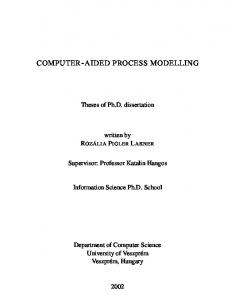
This transformation has been implemented in four different, independent graph grammars. This, as there are four well defined steps for completing the transformation, and there is no need to evaluate the applicability of the other rules, as none of them will be applicable. This makes the transformation process faster. Another reason to split the transformation is that it is easier to debug. The four graph grammars are: 1. The first graph grammar identifies the events in the Statechart by looking at the events each hyperedge has in its lists. It creates a Place for each event. In our approach, each type of event in the system is assigned a Place. These are considered interfaces in which the system puts a token whenever the event takes place. For each Orthogonal component in the Statechart model, the graph grammar creates “local” versions of the global events. Each global event is connected to the local events via a unique Transition, in such a way that when the global event is present, the token is broadcast to all the local events of the Orthogonal components. This global/local distinction is useful when an output event has to be sent: – If the event has to be sent to a particular Orthogonal component, a token will be placed in its corresponding local event Place. – If it has to be broadcast to the whole system, it will be placed in the global event Place. Note also that the local event Places are connected to a Transition whose purpose is to eliminate the token if it has not been consumed immediatelly after the event took place. This graph grammar is shown in Figure 6. Rule 4: genRegularOutputEventPlaces
Rule 1: genInputEventPlaces 1’
::=
edone