balt5/ku-bto/ku-bto/ku0203/ku0979-03a kroenink Sⴝ4 8/19/03 9:50 Art: 60979 Input-AU Techniques in Orthopaedics® 18(2):000–000 © 2003 Lippincott Williams & Wilkins, Inc., Philadelphia
Computer-Assisted Image-Guided Intramedullary Nailing of Femoral Shaft Fractures Eric J. Hazan,
M.D.,*
and Leo Joskowicz,
Ph.D.†
Summary: Closed reduction and intramedullary nailing under x-ray fluoroscopy is the current treatment of choice for femoral shaft fractures. However, many images are required to successfully perform the procedure, especially for distal locking of the nail, resulting in cumulative radiation exposure to the surgeon. Recently, computer-based technologies have been developed for surgical navigation, enabling the surgeon to accurately track in real-time the instruments, implants, and patient anatomy during a procedure. This article reviews the principles and potential benefits of computer-aided image-guided surgery for femoral shaft fracture, its indications, and its pitfalls. The existing systems, commercially available and prototypes, and the early clinical experience using this technique are also briefly discussed. Key Words: Computer-assisted orthopaedic surgery—Image-guided surgery—Femur fracture—Intramedullary nailing.
tools and fracture fragments, manipulate them without direct visual feedback, and obtain a new set of images to confirm the new position. Intraoperative complications stemming from the technical difficulties, especially during distal locking, has prompted research in computer-assisted surgery to improve the accuracy of fluoroscopy-based orthopaedic procedures. Two types of systems, fluoroscopy-based and computed tomography-based systems, have been developed to intraoperatively help the surgeons navigate and precisely position the anatomy and implants while dramatically reducing or eliminating altogether fluoroscopic x-ray imaging. The first type, also called virtual fluoroscopy, is commercially from several companies available and is reported to improve surgical accuracy.23
Femoral shaft fractures are best treated with interlocked intramedullary nailing, providing stable fixation to maintain longitudinal and rotational alignment to allow early active range of motion.2 The introduction of image intensifiers in the operating room has enabled the surgeon to perform both the reduction and stabilization without opening the fracture site, reducing further damage to the traumatized area and maximizing its biologic potential for healing. Closed antegrade nailing is a minimal exposure surgery and is currently the treatment of choice for femoral shaft fractures.26 However, a great number of fluoroscopic images are required in each step of the procedure to achieve successful anatomic reduction and stable fixation, resulting in cumulative radiation exposure to the surgeon, the surgical team, and the patient.14 Limitations from this technique arise because the images from the C-arm are uncorrelated two-dimensional views with a limited field-of-vision. The surgeon has to mentally correlate in time and space the surgical
LIMITATIONS OF THE CURRENT PROCEDURE The critical steps to a successful closed antegrade femoral nailing are all sensitively dependent on fluoroscopic imaging:
From the *División de Traumatología, Hospital de Ortopedia, Centro Nacional de Rehabilitación, Mexico City, Mexico; and the †School of Computer Science and Engineering, The Hebrew University of Jerusalem, Jerusalem, Israel. Address correspondence and reprint requests to Eric J. Hazan, MD, División de Traumatología, Hospital de Ortopedia, Centro Nacional de Rehabilitación, Ave. Mexico-Xochimilco 289, Mexico 14389 DF, Mexico. E-mail:
[email protected]
● Establishing the starting point exactly in the pyriformis fossa is crucial to ensure a proper nail position in the medullary canal and to avoid bone fragment mis1
balt5/ku-bto/ku-bto/ku0203/ku0979-03a kroenink Sⴝ4 8/19/03 9:50 Art: 60979 Input-AU
2
HAZAN AND JOSKOWICZ
alignment and fracture when inserting the intramedullary (intramuscularly) nail. ● Fracture reduction requires several images, especially when the guide wire is introduced into the distal fragment. Because the field-of-view of fluoroscopic images is limited, several takes are necessary to confirm proper alignment in the coronal and sagittal planes. Rotational position is inferred by gross observation of the patient’s patella orientation and by width mismatch of the proximal and distal bone fragments in the absence of comminution at the fracture site. Femoral anteversion is not routinely measured, even though 8% to 19% of the cases could develop a malrotation deformity of 15° or more compared with the uninjured side.1,27 ● Locking the distal holes is arguably the most demanding phase of the surgery. First, it requires a very accurate positioning of the C-arm, perpendicular to the distal nail longitudinal axis, until a perfect circle is seen. Second, if the drill tip skids over the convex surface of the femur when power drilling begins, the chance of aiming in the center of the hole are reduced. The surgeon needs to repeat this step, which is increasingly difficult at each pass, enlarge the existing entry point or create another one to correctly place the locking screw in the nail. This can potentially weaken the bone locally, jeopardizing the locking screw stability and the fracture fixation. Cumulative radiation is of concern, especially to the surgeon and surgical team who perform this surgery on a regular basis. Fluoroscopic times average between 4 and 5 minutes, but can increase up to 30 minutes in complicated cases. Close proximity to the patient or to the fluoroscopic beam enhances radiation exposure both directly and from scatter. The surgeon’s and his first assistant’s dominant hand, face, and neck, as well as the patient’s gonads are mostly affected, especially when they are within 24 inches of the radiation beam. During fracture reduction and distal locking, the surgeon’s hand is frequently within the fluoroscopic field, where direct beam radiation is 40 mSv per minute of fluoroscopy. The annual dose limit of radiation to the limbs is 500 mSv, as established by the International Commission on Radiation Protection and the Occupational Safety and Health Administration, equivalent of 12.5 minutes of direct beam fluoroscopic exposure. In an average case of intramedullary nailing of lower limbs, 1.27 mSv of radiation has been measured in the hands of surgeons mostly during distal locking, which alone can take up to 51% of the total fluoroscopic time.12–14 The importance of an experienced x-ray technician in the operating room cannot be overemphasized, because Techniques in Orthopaedics®, Vol. 18, No. 2, 2003
the quality of the images and the frequent changes in C-arm position around the patient translate directly into radiation exposure time.3 The same is true regarding the surgeon’s experience; as the trainee progresses through the learning curve to master this surgical technique, his or her radiation exposure decreases.12 The surgeon relies heavily on his or her hand– eye coordination during the entire procedure, mentally correlating the still fluoroscopic two-dimensional (2-D) images to the three-dimensional (3-D) anatomy and surgical tools that he or she is dynamically manipulating. This mental process is challenged with the more precise steps of the procedure such as distal locking, especially when the case is done during the night or early morning, as is often the case. Other limitations occur for preoperative planning and intraoperative measurements, because the images are 2-D projection, which are affected by the individual radiographic technique (such as emergency room films), peripheral distortion, therefore yielding only approximate values for bone length, canal width, and femoral anteversion.15,21 Some of the existing problems have been addressed with limited success. Several devices for distal locking have been developed such as fluoroscopic targeting tools, radiolucent drill guides, mechanical guides, and magnetic systems, none of which have really substituted the free-hand technique.11,24 The low-resolution, contrast-limited field of view and distortion of conventional fluoroscopy is improving significantly in the newest generation of motorized 3-D fluoroscopes. However, a large number of images are still necessary, and these are static views only. Other imaging modalities such as intraoperative magnetic resonance (MR) and computed tomography (CT) are not practical for femur fracture surgery. Ultrasound is currently under development for intraoperative use in orthopaedics, and could be a promising alternative once an acceptable resolution for fracture work is achieved. In summary, the current technique is limited by the radiation exposure, the high number of images necessary at each step, the variability in results, which depends on the surgeon’s skills, the lack of accurate measurement of axis and alignment, and the images’ limited field of view.
GOALS AND CAPABILITIES OF COMPUTERASSISTED SURGERY SYSTEMS Based on the previous section, the main goals of computer-assisted surgery (CAS)-based systems are: 1. To reduce the cumulative radiation exposure;
balt5/ku-bto/ku-bto/ku0203/ku0979-03a kroenink Sⴝ4 8/19/03 9:50 Art: 60979 Input-AU
COMPUTER-ASSISTED INTRAMEDULLARY NAILING 2. To reduce the complications stemming from alignment and positioning errors of bone fragments and surgical tools; 3. To improve the accuracy of distal locking; 4. To improve the surgeon’s hand– eye coordination by decreasing the burden of having to mentally correlate the images with the procedure; 5. To improve the preoperative planning: fracture assessment, bone length, canal width and anteversion measurements, matched implant selection; 6. To reduce the outcome variability by easing the skillacquisition learning curve; and 7. Preoperative planning can be done entirely on the computer and the information stored until retrieval in the operating room. Modeling technology allows the computing of geometric models and bone properties extracted from CT and x-ray images.8,20 These models are used to perform all anatomic measurements and to find an ideally matched implant, substituting the current practice using plain x-ray films.4,5 Imageprocessing techniques can significantly improve the quality of fluoroscopic images by enhancing contrast and eliminating geometric and intensity distortion, panoramic images can be created to overcome the limited field of vision.28 Three-dimensional CT data can give a better view of the fracture pattern and alignment both for planning and intraoperative navigation, but it is not likely to become a routine use in fracture surgery in term of additional costs, time, and practicality. Intraoperative navigation allows the surgeon to follow the position and orientation in 3-D of the bone fragments, surgical tools, and implants in real-time. This enabling technology gives maximal information and objective measurements of what is happening during the procedure on the computer display. The navigation computer creates a “virtual reality” view of the operative field by integrating information from the preoperative and intraoperative images with models of tracked tools and implants already recorded in the computer database. The bone fragments, tools, and implants are attached to trackers, and their position is continuously monitored and updated by the computer, which then calculates the relative position of each tracked element in space. The tracking technology can be optical (infrared) or magnetic, with a position and orientation accuracy well within 1 mm and 1° (Polaris and OptoTrack, Northern Digital, Canada). The position of the tracked objects is then correlated with the fluoroscopic images during the surgery. The surgeon can view on the screen the changes in position of the bone fragments as he manipulates them, their measurements in space, the position of tools
3
such as the drill tip and its projected trajectory on 2 planes simultaneously, locate the exact axis of the distal locking holes, and make corrections as he progresses through the case with very few fluoroscopic images taken.6,8,25 Another area of CAS research focuses on enhancing the surgical gesture by assisting the surgeon to perform manual tasks. These devices range from passive mechanical guides to robotic tools, motorized and controlled by a computer, with intraoperative navigation capability coupled to the preoperative planning information. In fracture surgery, 2 types show potential for routine use in the operating room: passive or semiactive arms that allow steady and precise spatial localization for drilling pilot holes, and semiactive/active robots to perform fracture reduction and distal hole targeting.8,18,19,25 CAS systems are designed to meet stringent safety requirements. In case of failure or complication during surgery, they can be easily stopped and removed, so the procedure could be completed conventionally at any given time. IMAGE-GUIDED SURGERY (IGS) Virtual Fluoroscopy Virtual fluoroscopy has emerged as the most viable technique for intraoperative navigation for femur fracture surgery. The system consists typically of: ● An optical tracking unit, which emits and receives infrared signals; ● One or more tracked frames placed on the patient’s anatomy, surgical tools, and implants; ● A computer unit and monitor(s); and ● A C-arm calibration ring. The underlying technical principles are fluoroscopic image correction and real-time tracking. Conventional fluoroscopic images are geometrically distorted and therefore need to be corrected for intraoperative navigation. The calibration ring has 2 plates on which a grid of fiducials (small crosses or spheres) is mounted. Because the distance between fiducials is known, the computer unit can measure from the images the distance variations caused by distortion and correct the image so that the fiducial distances are as they should be. The fluoroscopic image is now a spatially uniform lattice unto which the tracked elements will be superimposed. Tracking plates consist of 3 to 5 elements mounted on a rigid tree-like plate that either reflect (passive) light or emit (active) infrared signals. The optical unit detects the signal coming from the tracked element as they move in space and passes them to the computer, which calculates their exact Techniques in Orthopaedics®, Vol. 18, No. 2, 2003
balt5/ku-bto/ku-bto/ku0203/ku0979-03a kroenink Sⴝ4 8/19/03 9:50 Art: 60979 Input-AU
4
HAZAN AND JOSKOWICZ
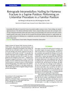
FIG. 1. Virtual fluoroscopy system in action (Hadassah EinKarem Hospital, Jerusalem, Israel).
position and orientation and correlates this information with corrected fluoroscopic images. The computer display shows simultaneously in 2 orthogonal planes the tracked elements as color-coded lines and continuously updates in real-time their position and orientation, which can also be read as numeric values of axis deviation. In the operating room, the set-up of the navigation equipment requires trained personnel to minimize prepTechniques in Orthopaedics®, Vol. 18, No. 2, 2003
aration time (Fig. 1). It is very important to place the optical unit in a position where its field of vision will be unobstructed. The patient is positioned on a fracture table and prepared in the usual fashion, the fractured side slightly overdistracted. Femoral anteversion can be calculated at this time by taking a set of orthogonal fluoroscopic images both proximally and distally on the uninjured femur. The surgeon can select on the screen 6
F1
balt5/ku-bto/ku-bto/ku0203/ku0979-03a kroenink Sⴝ4 8/19/03 9:50 Art: 60979 Input-AU
COMPUTER-ASSISTED INTRAMEDULLARY NAILING
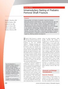
FIG. 2.
F2
5
(Figure continues)
reference points that will enable the computer to calculate the anteversion and bone length. A tracked plate is mounted on the nail insertion handle; the nail length and locking screw holes’ axis and position are registered with a tracked pointer. Both the plate and the pointer have to be in sight of the optical unit during this step. Next, a tracked reference frame plate is rigidly mounted on the cortex of the proximal femur fragment and a set of orthogonal fluoroscopic images is taken. The starting point is chosen without taking additional fluoroscopic images by following the color-coded line of a navigated drill on the screen (Fig. 2A). The drill axis and tip will be shown in a color and the projected drilling trajectory can be shown as an extension of the drill axis in a different color. The surgeon can continuously monitor the position and anticipated drill perforation line on the orthogonal fluoroscopic images simultaneously until an ideal portal is determined. Once the proximal reaming is performed, the reference frame is now moved to the anterolateral cortex of the distal femur. A new set of fluoroscopic images is taken to view the fracture site. A tracked reduction rod is then inserted and driven into the proximal femoral canal. Its virtual axis is seen as an advancing color line. A different color represents the distal fracture fragment virtual. Because the reference frame is on the
distal fragment, its virtual axis will not be seen moving during the manipulation of the fracture. Rather, it is the reduction rod virtual axis that will be moving relative to the distal fragment axis. Reduction is obtained once both virtual axes match on orthogonal planes. Note that the fluoroscopic images of the bone fragments do not move during this process, only the color lines of both virtual fracture axes. A guide wire is then inserted and the reaming can take place in the usual fashion, if so chosen. The navigated nail is inserted and a new set of fluoroscopic images is taken in the distal femur to verify its tip position. Femoral anteversion can now be corrected by manually adjusting the fracture in rotation until the desired angle is shown on the computer display. Two sets of orthogonal fluoroscopic images are taken, one for each distal hole locking. Two circles appear on the screen; the distal hole axis is obtained when both circles are concentric (Fig. 2B, C). The navigated drill axis is displayed simultaneously on the 2views. The rest of the procedure is done in the standard fashion. At any point in time the navigation can be interrupted and the case continued conventionally. Overall, roughly a dozen images are taken, significantly reducing radiation exposure. Furthermore, the surgeon does not even need to be close Techniques in Orthopaedics®, Vol. 18, No. 2, 2003
balt5/ku-bto/ku-bto/ku0203/ku0979-03a kroenink Sⴝ4 8/19/03 9:50 Art: 60979 Input-AU
6
HAZAN AND JOSKOWICZ
FIG. 2. (Continued) Tibial intramedullary nailing with the FluoroNav system (Medtronics, USA).
Techniques in Orthopaedics®, Vol. 18, No. 2, 2003
balt5/ku-bto/ku-bto/ku0203/ku0979-03a kroenink Sⴝ4 8/19/03 9:50 Art: 60979 Input-AU
COMPUTER-ASSISTED INTRAMEDULLARY NAILING to the radiation beam when images are taken, because all the critical steps are done under virtual guidance. Experimental distal locking studies showed a 100% success rate in placing the screws with less than 6 seconds of radiation exposure. The accuracy was very high, with only 11 of 102 screws touching the nail without damaging it.20,22 Early clinical experience reported by Suhm et al. on 42 intramedullary nailings yielded only 1 misplaced screw and 8 touching the nail. Fluoroscopy time ranged between 4 and 43 seconds (average, 16 sec) with an average surgical time of 43 minutes. Commercially available systems (Medtronics, USA; MediVision, Switzerland; BrainLab, Germany) share these technical principles but might vary in some of their features such as image recognition of bone, touch-screen menus, interface, and graphics. The set-up is straightforward and could only take a couple of minutes as the
7
newer navigation units can be wheeled where needed or ceiling-mounted such as arthroscopy towers. The time for registration and calibration is well compensated for by decreased fluoroscopy time and time saving for reduction and distal locking. Computed Tomography-Based Systems Preoperative CT enhances fracture pattern analysis, provides accurate anatomic spatial relationships, and allows for precise measurements and implant matching. Currently, CT-based CAS systems are used in spine, acetabular, and pelvic surgery, where these complex tridimensional anatomies are best evaluated. High-resolution 3-D images of the bone, surgical tools, and implants are simultaneously available in 3 planes to the surgeon during intraoperative navigation, offering dramatic improvement in surgical technique accuracy. Com-
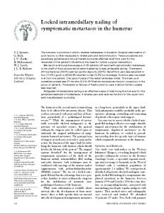
FIG. 3. FRACAS screen showing 3 views of the proximal and sagittal bone fragment models constructed from their computed tomography scans in the intraoperative position. The actual relative and absolute periaxial rotation angles are displayed at the bottom of the screen. Techniques in Orthopaedics®, Vol. 18, No. 2, 2003
balt5/ku-bto/ku-bto/ku0203/ku0979-03a kroenink Sⴝ4 8/19/03 9:50 Art: 60979 Input-AU
8
AQ: 1
F3
HAZAN AND JOSKOWICZ
puted tomography scans are not routinely performed in femur fracture cases as a result of increased costs, time, and practicality for conventional fracture surgery. However, some CAS systems offer a platform integrating the superior accuracy of CT imaging with the flexibility of intraoperative navigation. One such system is FRACAS, in which the preoperative planning includes all axis and bone length measurements, and the possibility to perform the entire surgical procedure virtually, including fracture reduction and implant selection.8 During intraoperative navigation, the surgeon relies on 3-D images and models in 3 dimensions in which surgical tools and implants are constantly updated without the need for further radiation (Fig. 3). All measurements can be done until the planned surgery goals have been met. The FRACAS system also provides a measure of the fractured bone periaxial bone rotation based on the healthy bone information.17 The prototype of the FRACAS system has been completed and in vitro experiments have been conducted. Several CT datasets of actual patients and dry bones were acquired. Preliminary evaluation by one surgeon of the modeling, validation, visualization, and preoperative planning indicates satisfactory results and ease of use, with planning times of approximately 15 to 20 minutes. A physical simulator was built to evaluate the ergonomics and accuracy of the system and to train surgeons. To validate the anteversion measurements, 3 dry femurs were CT scanned with a 2-mm slice interval and then were broken to simulate fractures and mounted on the simulator. Two different surgeons successfully performed the reduction within 2 minutes. The measured angle on the fractured femur was determined to be within 1° to 4.5° (3–13%) for bones with normal 18.5° to high (34.5°) anteversion. The repeatability of the fracture reduction was within a range of ⫾0.5°, which is a 2-fold improvement over previously published results. The FRACAS system can correlate fluoroscopic images with the preoperative CT images to avoid surface registration, which is not possible during closed intramuscularly nailing. Perhaps with the newest generation of high-speed helical CT scanners it will not be so inconvenient and expensive to obtain a femur CT in a polytrauma patient needing a scan of his head or abdomen if it can provide a faster, safer, and more accurate fracture surgery. POSITIONING SYSTEMS Although the previously described navigation systems allow the surgeon to reach a desired tool and anatomy configuration during surgery, they do not help maintain it during the surgical action. For distal locking, the systems Techniques in Orthopaedics®, Vol. 18, No. 2, 2003
FIG. 4. Photograph of the MARS robot (Mazor Surgical Technologies, Israel) mounted on the nail head.
guide the surgeon in aligning the drill axis with the distal hole axis but do not guarantee that the alignment will prevail when the drilling starts. The drill bit can slip when it touches the cortical bone and its axis can deviate from the distal hole axis as the drilling proceeds. To prevent this, a mechanical guide that maintains the axis alignment during drilling is needed. Two prototype systems have been developed to address this problem: the CAOS system for distal nailing was developed at the University of Hull, U.K.,16,25 and the bone-mounted MARS robot (Mazor Surgical Technology, Caesarea, Israel).8,18 The Hull system consists of a breakable, orientable passive arm with a drill guide, an optical tracker, and a computer. The system guides the user through a graphic display to align the axis of the drill guide with the axis of the distal holes as seen in anterior–posterior and lateral distal fluoroscopic images. Once the alignment is achieved, the passive arm is locked into position and the surgeon can drill the distal holes through the drill guide. It is assumed that the patient’s leg does not move between the time of fluoroscopic image acquisition and drilling time. A target accuracy of 1 mm and 1° error at the drill tip was achieved on plastic phantom bones. The main drawbacks of the system are that the passive arm is cumbersome and expensive, that it assumes no leg motion, and that it requires a tracking unit. The MARS system (Fig. 4) consists of a miniature robot fitted with a drill guide that provides mechanical guidance for manual drilling. The robot, which weighs only 150 g, is directly mounted on the bone (laterally, distal to the fracture line and proximal to the distal locking nail holes) or on the intramedullary nail’s head (through a supporting plate). The drill guide and the nail’s distal locking holes’ axes are automatically aligned
F4
balt5/ku-bto/ku-bto/ku0203/ku0979-03a kroenink Sⴝ4 8/19/03 9:50 Art: 60979 Input-AU
COMPUTER-ASSISTED INTRAMEDULLARY NAILING with a few x-ray fluoroscopic images. Mounting the robot directly on the nail or on the patient’s bone is minimally invasive, eliminates the need for leg immobilization, and obviates the need for real-time tracking. The MARS robot positional accuracy is 0.1 mm or better, which is by far sufficient. Preliminary in vitro results show a worst-case deviation of 1.5 mm and 2° between the drill guide axis and hole axis at the screw entry point, which is considered acceptable. DISCUSSION AND CONCLUSIONS As we have seen, the CAS systems described here address the geometric and positioning problems associated with the current femoral intramedullary nailing procedure. Most of the clinical data to date shows clear improvements when the systems are used, although this is not universal.7 Much work and clinical experience is still necessary to see these systems in routine clinical practice. Virtual fluoroscopy is the most commonly used CAS application. To date, approximately 500 systems have been installed in hospitals around the world, with the numbers expected to increase in the near future as the technology becomes familiar to surgeons and clinical studies show their advantages. It will enter common clinical use when the system prices drop, the learning curve is shortened, and multiple procedures can be performed with them. The FRACAS system, although offering the most comprehensive solution, requires a preoperative CT, which is not currently routine practice and needs to undergo clinical trials. The CAOS system for distal targeting assumes patient immobilization between the image acquisition time and the arm positioning. It also needs to undergo clinical trials. The CAS methods discussed here for intramedullary nailing of femoral fractures are also relevant in other clinical applications. Intramedullary tibial nailing is the closest one. Tibial nailing is easier than femoral nailing because there is less muscle mass for reduction and the nail suffers less deformation. However, guidance is still necessary for distal tibial nailing, and the methods described here are applicable with little or no modification. Other possible applications include femoral head fractures, hip fracture fixation, radius and shoulder fractures. It is our belief that real-time tracking will become an integral part of future interventional systems. Medical imaging equipment manufacturers are designing new systems in which real-time tracking is an integral part of the imaging procedure. The integration simplifies the system, provides better accuracy, and is more cost-effective. We also believe that small robotic systems directly mounted on the patient anatomy and guided with a few fluoroscopic
9
x-ray images hold great promise for precise targeting and drill positioning. 9,10
AQ: 2
REFERENCES 1. Braten M, Terjesen T, Rossvoll I. Femoral shaft fractures treated by intramedullary nailing. A follow-up study focusing on problems related to the method. Injury 1995;26:379 –383. 2. Brumback RJ. Regular and special features—the rationales of interlocking nailing of the femur, tibia, and humerus. Clin Orthop 1996;324:586 – 651. 3. Giannoudis PV, McGuigan J, Shaw DL. Ionising radiation during internal fixation of extracapsular neck of femur fractures. Injury 1998;29:469 – 472. 4. Hermann KL, Egund N. Measuring anteversion in the femoral neck from routine radiographs. Acta Radiol 1998;39:410 – 415. 5. Hofstetter R, Slomczykowski M, Krettek C, et al. Computerassisted fluoroscopy-based reduction of femoral fractures and antetorsion correction. Comput Aided Surg 2000;5:311–325. 6. Hofstetter R, Slomczykowski M, Sati L-P, et al. Fluoroscopy as an imaging means for computer-assisted surgical navigation. Comput Aided Surg 1999;4:65–78. 7. Hüffner T, Pohlemann T, Tarte S, et al. Computer-assisted fracture reduction: novel method for analysis of accuracy. Comput Aided Surg 2001:153–159. 8. Joskowicz L, Milgrom C, Simkin A, et al. FRACAS: a system for computer-aided image-guided long bone fracture surgery. Comput Aided Surg 1999;3:271–288. 9. Joskowicz L. Fluoroscopy-based navigation in computer-aided orthopaedic surgery. In: Isermann, et al., eds. Proc. of the IFAC Conf. on Mechatronic Systems, Darmstadt, Germany: Elsevier, 2000. 10. Joskowicz L, Milgrom C, Shoham M, et al. Robot-assisted system for long bone intramedullary distal locking. In: Lemke HU, et al., eds. Proc. of the 17th Int. Congress on Computer-Assisted Radiology and Surgery. Darmstadt, Germany: Elsevier, 2003. 11. Krettek C, Konemann B, Miclau T, et al. Mechanical distal aiming device for distal locking in femoral nails. Clin Orthop 1999;384: 267–275. 12. Madan S, Blakeway C. Radiation exposure to surgeon and patient during intramedullary nailing of the lower limb. Injury 2000;33: 723–727. 13. Mehlman CT, Di Pasquale TG. Radiation exposure to the surgical team during fluoroscopy: ‘how far away is far enough?’ J Orthop Trauma 1997;11:392–398. 14. Muller LP, Suffner J, Wenda K, et al. Radiation to the hands and thyroid of the surgeon during intramedullary nailing. Injury 1998; 29:461– 468. 15. Murphy S, Simon S, Kijewski P, et al. Femoral anteversion. J Bone Joint Surg [Am] 1987;69:1169 –1176. 16. Phillips R, Viant WJ, Mohsen AMMA, et al. Image guided orthopaedic surgery— design and analysis. Transactions of the Institute of Measurement and Control 1995;17. 17. Ron O, Joskowicz L, Simkin A, et al. Computer-based periaxial rotation measurement for aligning fractured femur fragments from CT: a feasibility study. Comput Aided Surg 2002;7:332–341. 18. Shoham M, Burman M, Zehavi E, et al. Bone-mounted miniature robot for surgical procedures: concept and clinical applications. IEEE Transactions on Robotics and Automation 2003. 19. Schmucki D, Messmer P, Suhm N, et al. Computer-Assisted Reduction—A New Concept for Fracture Treatment. Second Annual Meeting of the International Society for Computer Assisted Surgery; Santa Fé, NM; 2002. 20. Slomczykowski M, Hofstetter R, Strauss M, et al. Fluoroscopybased surgical navigation— concept and possible clinical applications. In: Nolte LP, Ganz R, ed. Computer Assisted Orthopaedic Surgery. Hogrefe and Huber Publishers, 1999:206 –217. Techniques in Orthopaedics®, Vol. 18, No. 2, 2003
AQ: 3
AQ: 4
AQ: 5
AQ: 6
AQ: 7
AQ: 8
balt5/ku-bto/ku-bto/ku0203/ku0979-03a kroenink Sⴝ4 8/19/03 9:50 Art: 60979 Input-AU
10
AQ: 9
HAZAN AND JOSKOWICZ
21. Sugano N, Noble P, Kamaric E. A comparison of alternative methods of measuring femoral anteversion. J Comput Assist Tomogr 1998;22:610 – 614. 22. Suhm N, Jacob AL, Nolte LP, et al. Surgical navigation based on fluoroscopy: clinical application for computer-assisted distal locking of intramedullary implants. Comput Aided Surg 2000;5:391– 400. 23. Suhm N, Jacob AL, Nolte LP. Surgical navigation reduces radiation doses during closed intramedullary nailing. In: Lemke HU, et al., eds. Proc. 15th Int. Symposium on Computer Assisted Radiology and Surgery. Springer, 2000:262–266. 24. Tyropoulos S, Garvanos C. A new distal targeting device for closed intramedullary nailing. Injury 2001;32:732–735.
Techniques in Orthopaedics®, Vol. 18, No. 2, 2003
25. Viant WJ, Phillips R, Griffiths JGA. Computer-assisted orthopaedic system for distal locking of intramedullary nails. In: Proc. of the Institute of Mechanical Engineers 1997;211:293–300. 26. Wolinsky PR. Fractures of the femoral diaphysis, including the subtrochanteric region. Orthopaedic Knowledge Update: Trauma 2. Rosemont, IL: American Academy of Orthopaedic Surgeons, 2000:133–146. 27. Yang KH, Han DY, Jahng JS, et al. Prevention of malrotation in femoral shaft fracture. J Orthop Trauma 1998;12:558 –562. 28. Yaniv Z, Joskowicz L. Long bone panoramas from fluoroscopic x-ray images. In: Lemke HU, et al., eds. Proc. of the 16th Int. Congress on Computer-Assisted Radiology and Surgery. Elsevier, 2001: 490 – 495.
AQ: 10
AQ: 11