9V DC source is switched and then stepped. DC. A list of equipment used is given Table 1. Table 1: Equipment Used. Name. Model/Speci. Timer IC. LM555.
Computer Based Radioactivity Measurement with Acquisition and Monitoring Radiation Data Using LabVIEW Masudul Hassan Quraishi1, Md. Aminul Hoque1, Anisa Begum2, Mohammad Jahangir Alam1 1
Dept. of Electrical and Electronic Engineering, Bangladesh University of Engineering and Technology, Dhaka, Bangladesh 2
Electronics Division, Atomic Energy Center, Dhaka, Bangladesh
Abstract— This paper presents preparing high voltage for Geiger counter along with data acquisition and monitoring technique by LabVIEW. A high voltage generation circuit is designed for the GM counter and the recorded data is stored, analyzed and monitored in a personal computer with the help of National Instruments Data Acquisition card (DAQ card). The interface between hardware and computer is done by the software LabVIEW. Keywords-radiation detection, LabVIEW, data acquisition, GM counter, DAQ
I.
INTRODUCTION
Radiation is the energy that comes from a source and travels through some material or through space. This paper is mostly concerned about ionized radiation. Ionized radiation is produced by unstable atoms which contain excess of energy or mass. The importance of detecting natural radiation is that certain radiations are harmful for environment. As ionized radiation is used in diagnosis of diseases, medical and scientific researches and nuclear power plants, detection of radiation is an important task [1]. The objective of this work is to implement a cost effective Radiation Measurement System. It has been implemented using DAQ and LabVIEW to record the data and store in a computer. For making this system cost effective, Geiger Muller radiation detector has been used [2]. The high voltage generation circuit mainly consists of a simple transformer and passive elements such as capacitors, diodes and resistors. The key idea is to develop a cheap hardware which can detect radiation up to a satisfactory accuracy and also to record the data into a secure database with easy access. II.
FAMILIARIZATION WITH RADIOACTIVITY AND DETECTION SCHEME
Radiation is a process in which energetic particles or energetic waves travel through vacuum, or through mattercontaining media that are not required for their propagation. Waves of a massive medium itself, such as water waves or sound waves, are usually not considered to be forms of "radiation" in this sense. Two energies of radiation are commonly differentiated by the way they interact with normal chemical matter: ionizing and non-ionizing radiation. Both ionizing and non-ionizing radiation can be harmful to organisms and can result in changes
to the natural environment. In general, however, ionizing radiation is far more harmful to living organisms per unit of energy deposited than non-ionizing radiation. Since the ions that are produced by ionizing radiation, even at low radiation power, have the potential to cause DNA damage. By contrast, most non-ionizing radiation is harmful to organisms only in proportion to the thermal energy deposited. It is conventionally considered harmless at low powers which do not produce significant temperature rise. There are mainly three types of ionized radiation: alpha (α), beta (β) and gamma (γ) rays [3]. This paper is more concerned about the gamma ray detection. Gamma (γ) radiation consists of photons with a frequency of greater than 1019 Hz [4]. Gamma radiation occurs to rid the decaying nucleus of excess energy after it has emitted either alpha or beta radiation. Both alpha and beta particles have an electric charge and mass, and thus are quite likely to interact with other atoms in their path. Gamma radiation is composed of photons, which have neither mass nor electric charge. Gamma radiation penetrates much further through matter than either alpha or beta radiation. Gamma rays, which are highly energetic photons, penetrate deeply and are difficult to stop. They can be stopped by a sufficiently thick layer of material, where stopping power of the material per given area depends mostly (but not entirely) on its total mass, whether the material is of high or low density [5]. Radiation detector is a device used to detect, track, and/or identify high-energy particles, such as those produced by nuclear decay, cosmic radiation, or reactions in a particle accelerator. The different types of detectors are divided into three groups: a.
Inorganic detectors
b.
Organic detectors
c.
Gaseous detectors
In this paper, radiation detection is implemented by gaseous detectors. Gas-filled detectors consist of a volume of gas between two electrodes [6]. There are basically two types of modes of operation. They are: a.
Pulse mode
b.
Current mode
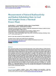
In pulse mode, the signal from each interaaction is processed individually. In current mode, the electriical signals from individual interactions are averaged togethher, forming a net current signal. To be more specific, a Geigerr Muller detector is used here, which contain gases with specificc properties. When appropriate bias (in this case, nearly 500V)) is applied, upon receiving radiation (gamma rays) the detectoor produces current pulses. The schematic diagram of the detectoor circuit is shown in Figure 1[7].
D for the High Voltage Figure 2: Schematic Circuit Diagram Generattion Unit Figure 1: Schematic Diagram for a Geiger Mulller Gas detector
Therefore, the whole work can be divided intto two major parts: a. High Voltage Generation unit b. Data Acquisition Unit These are described in the following sections. N UNIT III. HIGH VOLTAGE GENERATION
Geiger-Muller counter operates at high DC voltage. The DC voltage is applied at two electrodes off the counter. The counter used here has an operating voltage range r of 450-650V [8]. The hardware built here is basically a DC C-DC converter. A 9V DC source is switched and then stepped up to make 500 V 1 DC. A list of equipment used is given Table 1.
The operation of the circuit is straight forward. The timer is operated in Astable mode to generate pulse. The following output pulse was extracted from the timer: Frequency=146Hz and Duty= 0.48. I is used to switch the input 9V The output from 555 timer IC supply. Switching is perform med by IRF540 MOSFET. The switched output is stepped up via a transformer. A 220V/6V step down transformer is operaated in step up mode to achieve amplified pulse. mer is passed through voltage Output from the transform multiplier circuit for further am mplification [10].
Table 1: Equipment Used d Name
Model/Speciification
Timer IC
LM555
Transformer
220V-6V Steep Down
MOSFET
IRF540
Diode
1N4007
BJT
BC549C
Capacitors
100nF, 10uF,, 1000uF
Resistors
5k, 68k, 1M, 100k, 1k
Battery
9V
Potentiometer
100k
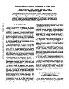
t high voltage The schematic circuit diagram for the generation unit is shown in Figure 2[9].
Figure 3: Basic Voltagge Multiplier (Doubler) In the voltage doubler circcuit shown in Figure 3 the first diode rectifies the signal and its output is equal to the peak voltage from the transformer rectified as a half wave rectifier. An AC signal via the capacitorr also reaches the second diode, and in view of the DC block provided by the capacitor this causes the output from the secoond diode to sit on top of the first one. In this way the output froom the circuit is twice the peak voltage of the transformer, less the diode drops.
Figure 4: Hardware setup forr high voltage generation
Figure 4 shows the hardware setup for high voltage generation. The high voltage board must have a protection circuit for safety. If voltage higher then rated voltage is generated, excess current flow might damage the Geiger counter. The high voltage output is fed to input of a BJT. Whenever the current flow exceeds limit, the transistor switches the reset pin of 555 timer to ground. The timer is reset and pulse generation is stopped immediately which sets the high voltage output to zero volts. Voltage output can be varied a small amount by adding a potentiometer at the output. Output voltage also varies proportionally to input voltage. The high voltage board is particularly built for the specific GM counter model. Therefore varying the voltage in wide range is not necessary. Just a little tuning might be needed to get the counter in its best performance voltage range.
Figure 5: Front Panel
Thus the hardware setup for the counter is ready. The counter will produce output pulse in response of radiation field around it. In the next chapters focus will be on the counter interfacing with computer using LabVIEW and acquisition the count data from GM counter to the computer. IV.
DATA ACQUISITION UNIT
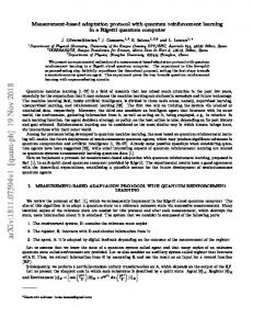
For the interfacing with computer for data recording and handling, LabVIEW and NI DAQ card are used. LabVIEW (Laboratory Virtual Instrumentation Engineering Workbench) is a dataflow programming language developed by National Instruments (NI). Applications developed for this work are programmed in LabVIEW 2009 version. Data acquisition is the process of sampling signals that measure real world physical conditions and converting the resulting samples into digital numeric values that can be manipulated by a computer. The data acquisition device used hereis NI USB-6009. It is 14-bit, 48 kS/s low cost multifunction DAQ card [11]. NI USB-6009 DAQ card has its digital trigger or event counter input at PFI0 pin. Output from the GM counter is connected to PFI0 pin of DAQ card. When radiation is detected, output pulse from GM counter goes to DAQ card and the count is stored and monitored in computer using LabVIEW program. A virtual instrument is created using LabVIEW for proper collection, storage and monitoring of radiation data. The task is completed by building small blocks performing certain actions. The major blocks are: a. Elapsed Time Block b. Counter Block c. File Read and Plot d. Security Alarm All the blocks mentioned above are combined to form the virtual instrument for acquisition and monitoring data. Front panel of this instrument is shown in Figure 5.
Figure 6: Block Diagram of Interfacing Algorithm Radiation data saved in excel file is used to make daily database of radiation. The database can be searched by year, month and date. Therefore the system stores entire radiation history in the computer. The whole procedure is summarized and depicted by a flow diagram in Figure 6. The radiation data can be used to plot daily, monthly or yearly radiation history plot. Front panel of database is shown in Figure 7.
VI. CONCLUSION
Figure 7: Radiation Database V. LIMITATIONS AND SOLUTIONS The implemented system is a state of art radiation measurement and monitoring system. However, it has few limitations and scope of improvements. The current LabVIEW program is suitable for low frequency measurement due to the limitation of NI USB-6009 DAQ Card. High frequency measurement is possible by replacing DAQ Card with an advanced one. GM counters are not suitable for high radiation field; they are paralyzed when the count rate is too high. In order to get better results, scintillation detectors may be used. Noise removal hardware is absent in the system. Due to external noise, results can be varied a little bit. It can be resolved by using noise removal circuitry between GM counter and DAQ card. The system can be further enhanced by introducing complete wireless control.It can be achieved by internet or Bluetooth or any other wireless means of communication. GM counter and computer setup room will be near the radiated zone and can be controlled from thousands miles away by internet. The database will be available in a website so that radiation information can be accessed from anywhere. For test purpose, only GM counter is used in the system. Output range of the high voltage board can be increased to supply different types of radiation counter. Thus the current system can be upgraded to universal radiation measurement system.
The implemented system is an inexpensive and easy to use method for Radiation Detection and Measurement. The main advantage of the implementation is that a less expensive and simple circuit is designed for the detector, consisting of locally available equipment. The software used for computer interfacing is also open source (NI LabVIEW 8.1 Student Edition) software. Although a data acquisition card (NI USB6009) is used, alternatively a micro-controller based data acquisition system could be used for reducing the cost further. Additionally, in LabVIEW virtual window, one can setup experiments which may be impossible to construct in real life. Furthermore, it creates a safe environment for the student, since there is no real radiation risk and also no possible damage risk to the expensive instruments, while learning radiation detection and measurement. REFERENCES [1] [2] [3]
“Radiation detection and measurement” Glenn F. Knoll “Data acquisition” http://en.wikipedia.org/wiki/Data_acquisition Kwan-Hoong Ng (20–22 October 2003) Questions and Answers about Biological Effects and Potential Hazards of Radiofrequency Electromagnetic Fields. Office of Engineering and Technology. Bulletin 56, Fourth Edition, August 1999.. [4] "Non-Ionizing Radiations – Sources, Biological Effects, Emissions and Exposures". Proceedings of the International Conference on NonIonizing Radiation at UNITEN ICNIR2003 Electromagnetic Fields and Our Health. [5] "The History of the Discovery of Radiation and Radioactivity" http://mightylib.mit.edu/Course%20Materials/22.01/Fall%202001/disco very%20of%20radiation.pdf [6] R.K.BOCK, A.VASILESCU,"The Particle Detector Briefbook" Rudolf K.Bock, March 1999 [7] Helmuth Spieler, “Introduction to Radiation Detectors and Electronics”Lecture Notes - Physics 198, Spring Semester 1998 - UC Berkeley [8] Mullard, Quick Reference Guide 1977/78, “ZP-1320 Datasheet” [9] Ajarn Changpuak, “Homebrew Geiger Müller Counter,”December, 2011 [10] Ian Poole, “Diode voltage multiplier circuit,” March 2001: http://www.radioelectronics.com/info/circuits/diode_voltage_multiplier/diode_volt_mult. php [11] National Instruments Corporation,“NI USB-6008/6009 User Guide and Specifications,” February, 2012.