David Abookasis and Joseph Rosen .... from thee planar surfaces carrying the letters C, G, H, on each one ... z)=(-l70,0,-170), and the 'H' ball was at the front of.
COMPUTERGENERATED THREE TYPES OF HOLOGRAMS OF THREE-DIMENSIONAL OBJECTS SYNTHESIZED BY MULTIPLE PERSPECTIVES David Abookasis and Joseph Rosen
Ben-Gunon University of the Negev Department of Electrical and Computer Engineering P. 0. Box 653.Beer-Sheva 84105. Israel ABSTRACT A new method of synthesizing computer-generated holograms of three-dimensional (3-D) objects is proposed. Several projections of the 3-D object are numerically processed to yield a two dimensional complex function, which is then encoded as a computergenerated hologram. When this hologram is illuminated by a plane wave, a 3-D real image of the object is reconstructed. Although the hologram initially belongs to the type of Fourier holograms, Fresnel and image holograms are also generated by computing the propagation of the wave front from the Fourier plane to any other desired plane. Computer and optical constructions of >D objects, both of which show the feasibility of the proposed approach, are presented herein.
1. INTRODUCTION
Conventional holographic recording demands special stability of the optical system and relatively intense light with a high degree of coherence between the involved beams [ I]. These requirements have prevented hologram recorders from becoming as widely used for outdoor photography as conventional cameras. In this article we will review recent developments in a new method of holographic computer-aided imaging. In this method, a hologram is computed from a set of angular projections ofthe observed 3D object. The entire sets are numerically processed to yield a two-dimensional complex function, which is then encoded as a computergenerated hologram (CGH). When this hologram is illuminated by a plane wave, a 3D real image ofthe object is reconstructed. The main feature of this hologram is that its transparency values are identical to a Fourier hologram recorded by an interference between two laser beams. It is important to note that this hologram is not related to the well-known multiplex or stereoscopic
&78034427-~20.00@2004IEEE
holograms [2]. The main advantage of this technique is that, although objects in the scene can be recorded by a conventional digital camera without wave interference, the process yields a hologram of the observed scene with 3D features. In principle,once we have the Fourier wavefront distribution, other CGHs are obtained by computing the Fresnel propagation of the wavefront from the Fourier plane to any other desired plane. A critical factor limiting the amplitude computergenerated, and optical, holograms is their inherent low diffraction efficiency. Such efficiency is not tolerable for many practical applications. Therefore, in addition to the above mentioned CGHs, we revisit the topic of Fourier CGH, but at this time the diffraction efficiency is considered. The improved diffraction efficiency is achieved by multiplying the object with a random phase function [3]. Consequently, the spatial spectrum of the modified object spreads more uniformly over the entire spectral region. This technique is effective only because the phase distribution of the reconstructed image is not detectable by the viewer eyes. However introducing random phase on the objects causes to intensity fluctuations (speckles) on the image which might damage the smooth texture of the reconstructed image.
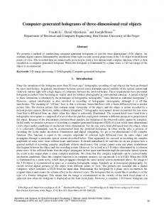
2 . 3 D CGH ALGORITHM USING MULTIPLE OBJECT PERSPECTIVES Before describing the various types of CGHs, we briefly summarize the algorithm for synthesizing Fourier CGH from multiple perspectives presented extensively in Ref. 4, and depicted in Fig. I . The first step in the algorithm is to generate a 3 D object in the computer memory. Next, the set of the object's angular projections are computed. Then, each projection is multiplied by a corresponding phase function and the p d u c t is summed to a single complex value. The end product of the process is a single two-
254
dimensional complex function representing the wavefront distribution on the hologram plane. Every complex value in this function is computed from a different angular projection and is positioned in the same order of observing the projected images. Finally, the given complex matrix is coded to a real and positive-valued matrix in order to be used as a holographic transparency. The complete computational process is illustrated schematically in Fig. 1. In Ref. 4 we have shown that the above algorithm generates a single complex function s(m.n) equal to the wavefront on the Fourier plane sampled in the m,n points. Therefore, the resulting CGH is equivalent to an optical Fourier hologram of a realistic 3-D scene recorded by a coherently illuminated system.
computer we add a reference wave function at the middle plane of reconstructed volume.
:
3. FOURIER, FRESNEL AND IMAGE c G n s As mentioned above. our algorithm creates a single complex functions(m.n) from the entire projections sets. We have shown in Ref. 4 that this complex function in continuous coordinates (u,v) is related to the 3-D object function. Therefore s(u,v) is equivalent to Fourier hologram recorded by a coherently illuminated system but with a 3 D object as the system's input. In order to improve the diffraction efficiency the magnitude distribution on the hologram plane should be more uniform. In this study we increase the uniformity of the hologram magnitude by multiplying the object function with a random phase. In analog to optical holography this factor acts like using different diffuser function. Since the resulting hologram s(u,v) is equivalent to the wavefront on a Fourier plane, it is possible to create a Fresnel hologram by computing the propagation of the wavefront from the Fourier plane to any other desired plane [SI. According to the Fresnel diffraction equation the complex amplitude on the plane located a distance z is a convolution between the object and the point-spread function (PSF) of the free space. In order to get the &sired Fresnel hologram, the Fourier spectrum of the object is multiplied by a quadratic phase function and by linear phase function. This linear function represents the tilt reference wave with respect to the propagation axis in order to overcome the twin image effect. The real part of the inverse Fourier transform of the product yields the desired Fresnel hologram of type 1. In the case of Fresnel hologram type-ll the procedure is modified such that the reference beam is added digitally to the Fresnel diffraction in a similar manner as in optical holography. The last type of hologram we demonstrate in this study is the image hologram [6].After applying the inverse Fourier transform on the spectrum patterns(u.v), the image volume is reconstructed in the computer. In the
51t.Il
SIl.2i
....
'
....
;j
SIrn."l
E3
Figure 1: CGH algorithm.
4. EXPERIMENTAL RESULTS In the experiment of the Fourier CGH with improved diffraction efficiency, the testing objects were composed from t h e e planar surfaces carrying the letters C, G , H, on each one of them. The 'C' plane was located at the back of pixels, the 'G' the scene at point (x,y,z)=(-l70,170,-170) plane was at the center of the scene at point (x,y,z)=(O,O,O) and the 'H' plane was at the front of the scene at point (x,y,z)=( 170, -170, 170) pixels. Each letter in the object plane was multiplied by a random phase function. The 3-D scene was observed from an incrementally changed angle from top to bottom in the azimuthal and elevation angles of +IOo, where the angular displacement between every two successive projection was 0.1" in both directions. From 201 ~ 2 0 1projections of the 3-D scene, the Fourier hologram pattern was computed according to the procedure sketched in Fig. 1.
255
.
The central lOOxl00 pixels of the magnitude of the Fourier hologram compared to the magnitude without the random phase technique are shown in Figs. 2(a) and 2(b), respectively. From these figures it is evident that the spectrum plane in Fig. 2(a) has more uniform magnitude distribution throughout the hologram plane owing to the additional random phase.
@) Figure 2: Enlarged portion of (a) the magnitude with random phase and (b) without random phase of the CGH generated by the algorithm shown in Fig. I . (a)
Fig.3 shows that at each transverse plane, a different letter o f different planes is in focus; thus reconstruction of the 3-D objects is demonstrated. In the second experiment we synthesizedthe two-types of the Fresnel hologram discussed previously. In he tested object of the Fresnel CGH type-l the ball with the letter 'c'was at the back o f the scene at point (x.~.z)=(-l70,0,-170),and the 'H' ball was at the front of the scene at point (x.y.z)=( 170, 0,-170). In the case of Fresnel CGH type-ll the testing object was composed of three balls carrying the letters C, G, H, located in the Same space coordinate as the three planes of the Fourier CGH mentioned above. The difference from the Fresnel hologram type-I is the addition of one more ball between the other two balls, carrying the letter G and located at the center of the scene at point @,y.z)=(O,O,O).The Fresnel hologram type-I is shown in Fig. 4 and theoptical reconstruction is shown in Fig.5
To observe the holographic reconstruction we illuminated the four computed CGHs displayed on an SLM (CRL, XGA3) with a collimated beam emerging from a He-Ne laser radiating at 632.8nm. Several experiments were conducted to verify the abovementioned concept. The Fourier hologram was encoded into positive, real valued function in order to be displayed on the.SLM. The reconstruction results in the vicinity of the back focal plane of the Fourier lens (f=750mm) are shovh in the Fig. 3. The entire pictures were captured with an 8-bit 795x596 pixels CCD at three different transverse planes along the optical axis; 733, 762, and 790mm from the lens. The distance between the lens and the SLM was 75mm.
Figure 4: Enlarged portion of the color inverted intensity distribution of the Fresnel CGH type-I.
z Figure 5: Optical reconstruction of Fig. 4 (Fresnel CGH type-I) in the vicinity of the back of the lens, for two transverse planes at 525mm and 565 mm along z axis. Figure 3: Optical reconstrtction ofthe hologram shown in Fig. 2(a). The contrast in these figures has bee inverted for better visualization.
The hologram pattern and the reconstruction from the Fresnel CGH type-ll are shown in Fig. 6 and Fig. 7. respectively. Those figures show that at each transverse
256
plane a different letter of a different ball is in focus, indicating the success of the 3-D construction. Finally the image CGH is considered. The 3-D object used here was composed of three cubes carrying the letters B, G, U, one on each of them. The ' B cube was at the back of the scene at point (~.y,z)=(-l25,0,-125) pixels, the 'G' cube was at the center of the scene at point (x,y,z)=(O,O,O) and the 'U' cube was at the front of the scene at point
Figure 8: Enlarged portion distribution o f t h e Image CGH.
of the
intensity
Figure 9: Optical reconstruction of the Image hologram shown in Fig. 8; (a) the 'U' cube at 605mm and (b) 320mm from the SLM by using imaging lens.
Figure 6: Enlarged portion of the intensity distribution
4. CONCLUSION
Figure 7: Ootical reconstruction of Fie. - 6 .(Fresnel CGH type-ll) in the vicinity of the back of the lens, for three transverse planes at 740mm. 780 mm and 810mm. (x.y.z)=(l25,0,-125) pixels. Each cube has the size of 8 5 x 8 5 ~ 8 pixels. 5 Asmentioned above, the process starts from the algorithm of synthesizing the Fourier CGH. By computing the inverse Fourier transform o f the hologram the images of the balls are digitally reconstructed. Then w add a reference wave in the computer and get the desired image hologram, shown in Fig. 8. The object reconstruction along the propagation axis z at three different locations with respect to the hologram plane is shown in Fig. 9. The reconstruction results of the image CGH without any lens between the hologram and the observer are shown in Fig. 9(a) while in 9(b) we used an imaging lens e 4 0 0 m m ) only for improving the visualization. The distance between the lens and the SLM was I20mm. L
In conclusion, we have presented and successfully demonstrated the evaluation of a new process for computing CGHs of the types Fourier, Fresnel and image holograms. A 2-D complex function is obtained from multiple view projections of a 3-D object. This function contains the 3-D information of the object and it is related to the object's Fourier transform. Consequently, we succeeded in creating Fresnel and image CGHs by using the Fresnel diffraction equations. The loss of quality in the pictures of the optical reconstruction is due to experimental difficulties such as nowuniform illumination, noise introduced by the optical elements, and the poor quality of the SLM. These metho& haw a high potential in versatile holographic applications such as 3 - D cameras and displays. 5. REFERENCES [I] D.Gabor, "A new microscope principle,"Norwe 161, pp.777-778, 1948. [2] T. Yatagai, "Stereoscopicapproach to 3Ddisplay using L pp. 2722computer-generatedholograms," Appl. O ~ 15,
2729, 1976. [3] H. Akahori, "Comparison ofdeterministicphase coding with random phase coding in terms of dynamic range." Appl. Opt. 12, pp. 23362343. 1973. [4] D.Abookasis and J. Rosen. "Canputer-generatedholograms
ofthreedimensionalobjects synthesized from their multiple angularviewpoints." J. Opt. Soc. Am. A 28, pg. 1537-1545,2003 [5] A. P. Hariharan, OpricalHolograp/y 2' ed. (Cambridge New York 1996).Chap. 2, pp. 19-21. [6] C. B. Brandt, "Image plane holography." Appl. Opr. 8, pp. 12W36, 1969.
251