Newport warrants that this product will be free from defects in materials and ...
operating procedures per the product specification or operators manual or ...
Computer Interfacing Manual
Newport Corporation, Irvine, California, has been certified compliant with ISO 9002 by the British Standards Institution. Corporate Headquarters Newport Corporation 1791 Deere Avenue Irvine, CA 92714 Telephone: 949-863-3144 Facsimile: 949-253-1800 Belgium Telephone: 016-402927 Facsimile: 016-402227
Canada Telephone: 905-567-0390 Facsimile: 905-567-0392 France Telephone: 1-60 91 68 68 Facsimile: 1-60 91 68 69 Germany Telephone: 06151-36 21-0 Facsimile: 06151-36 21-52
Italy Telephone: 02-924-5518 Facsimile: 02-923-2448 Japan Telephone: 03-5379-0261 Facsimile: 03-5379-0155
Netherlands Telephone: 030-6592111 Facsimile: 030-6570242 Switzerland Telephone: 01-740-2283 Facsimile: 01-740-2503
Taiwan R.O.C. Telephone: 2-2769-9796 Facsimile: 2-2769-9638 United Kingdom Telephone: 01635-521757 Facsimile: 01635-521348
Limited Warranty Newport warrants that this product will be free from defects in materials and workmanship for a period of two years from the date of shipment. If any such product proves defective during the applicable warranty period, Newport, at its option, either will repair the defective product with charge for parts and labor or will provide a replacement in exchange for the defective product. In order to obtain service under this warranty, the customer must notify Newport of the defect before the expiration of the warranty period and make suitable arrangements for the performance of service. In all cases the customer will be responsible for packaging and shipping the defective product back to the service center specified by Newport, with shipping charges prepaid. Newport shall pay for the return of the product to the customer if the shipment is within the continental United States, otherwise the customer shall be responsible for all shipping charges, insurance, duties and taxes, if the product is returned to any other location. This warranty shall not apply to any defect, failure or damage caused by improper use or failure to observe proper operating procedures per the product specification or operators manual or improper or inadequate maintenance and care. Newport shall not be obligated to furnish service under this warranty 1) to repair damage resulting from attempts by personnel other than Newport’s representatives to repair or service the product; 2) to repair damage resulting from improper use or connection to incompatible equipment; 3) to repair damage resulting from operation outside of the operating or environmental specifications of the product. NEWPORT’S LIABILITY FOR THE MERCHANTABILITY AND USE OF THE PRODUCT IS EXPRESSLY LIMITED TO ITS WARRANTY SET OUT ABOVE. THIS DISCLAIMER AND LIMITED WARRANTY IS EXPRESSLY IN LIEU OF ANY AND ALL REPRESENTATIONS AND WARRANTIES EXPRESS OR IMPLIED, INCLUDING BUT NOT LIMITED TO, ANY IMPLIED WARRANTY OF MERCHANTABILITY OR OF FITNESS FOR PARTICULAR PURPOSE, WHETHER ARISING FROM STATUTE, COMMON LAW, CUSTOM OR OTHERWISE. THE REMEDY SET FORTH IN THIS DISCLAIMER AND LIMITED WARRANTY SHALL BE THE EXCLUSIVE REMEDIES AVAILABLE TO ANY PERSON. NEWPORT SHALL NOT BE LIABLE FOR ANY SPECIAL, DIRECT, INDIRECT, INCIDENTAL OR CONSEQUENTIAL DAMAGES RESULTING FROM THE USE OF THIS PRODUCT OR CAUSED BY THE DEFECT, FAILURE OR MALFUNCTION OF THIS PRODUCT, NOR ANY OTHER LOSSES OR INJURIES, WHETHER A CLAIM FOR SUCH DAMAGES, LOSSES OR INJURIES IS BASED UPON WARRANTY, CONTRACT, NEGLIGENCE, OR OTHERWISE. BY ACCEPTING DELIVERY OF THIS PRODUCT, THE PURCHASER EXPRESSLY WAIVES ALL OTHER SUCH POSSIBLE WARRANTIES, LIABILITIES AND REMEDIES. NEWPORT AND PURCHASER EXPRESSLY AGREE THAT THE SALE HEREUNDER IS FOR COMMERCIAL OR INDUSTRIAL USE ONLY AND NOT FOR CONSUMER USES AS DEFINED BY THE MAGNUSOM-MOSS WARRANTY ACT OR SIMILAR STATE CONSUMER WARRANTY STATUTE.
©1997, Newport Corporation Irvine, California, USA Part No. 24595-01 IN-08974 Printed 2-Dec-98 Rev. B
TABLE OF CONTENTS 1. Computer Interfacing _____________________________________________1 1.1
Introduction ______________________________________________________ 1
1.2
Specific Controller Support _________________________________________ 1
1.3
GPIB Interface ___________________________________________________ 1
1.3.1 1.3.2 1.3.3
1.4
RS-232C Interface_________________________________________________ 3
1.4.1 1.4.2 1.4.3 1.4.4 1.4.5
1.5
Introduction _________________________________________________________ RS-232C Communication _______________________________________________ RS-232C Parameters___________________________________________________ Terminal Mode _______________________________________________________ Setting the Baud Rate __________________________________________________
3 3 3 4 4
ANSI/IEEE-488.2 Definitions________________________________________ 4
1.5.1 1.5.2 1.5.3 1.5.4
1.6
Preparation for Bus Control _____________________________________________ 1 Interface Function Subsets ______________________________________________ 1 Remote Messages _____________________________________________________ 2
Power-on Conditions __________________________________________________ 5 White Space _________________________________________________________ 5 __________________________________________________________ 5 Message Terminators __________________________________________________ 5
Status Reporting __________________________________________________ 6
1.6.1 1.6.2
Event and Condition Registers ___________________________________________ 7 Operation Complete Definition___________________________________________ 8
1.7
Output Off Registers_______________________________________________ 9
1.8
Overview of the Controller Device Dependent Commands ______________ 10
1.8.1 1.8.2 1.8.3 1.8.4 1.8.5 1.8.6
1.9
Active Laser and TEC Channel _________________________________________ 11 Substitute Parameter Names ____________________________________________ 11 Compound Command Structure _________________________________________ 12 Advanced Programming _______________________________________________ 12 Path Specification ____________________________________________________ 13 Timing Considerations ________________________________________________ 15
ILX Lightwave Corporation LDC-3900 and LDC-3700 Users____________ 16
2. Commands and Queries __________________________________________19 2.1
IEEE 488.2 Common Commands and Queries ________________________ 25
*CAL? ____________________________________________________________________ *CLS______________________________________________________________________ *ESE ______________________________________________________________________ *ESE? _____________________________________________________________________ i
25 25 25 26
*ESR? _____________________________________________________________________26 *IDN? _____________________________________________________________________27 *IST? ______________________________________________________________________27 *OPC ______________________________________________________________________28 *OPC? _____________________________________________________________________28 *PRE ______________________________________________________________________28 *PRE? _____________________________________________________________________29 *PSC ______________________________________________________________________29 *PSC? _____________________________________________________________________30 *RCL ______________________________________________________________________31 *RST ______________________________________________________________________31 *SAV ______________________________________________________________________32 *SRE ______________________________________________________________________32 *SRE? _____________________________________________________________________33 *STB? _____________________________________________________________________34 *TST? _____________________________________________________________________34 *WAI ______________________________________________________________________34
2.2
Device Dependent Commands and Queries. ___________________________ 36
BEEP ______________________________________________________________________36 BEEP? _____________________________________________________________________36 BRIGHT ___________________________________________________________________36 BRIGHT? __________________________________________________________________37 CONTRAST ________________________________________________________________37 CONTRAST? _______________________________________________________________37 DELAY ____________________________________________________________________37 EQUIPment? ________________________________________________________________38 ERRors?____________________________________________________________________38 ERRSTR? __________________________________________________________________39 INVERT ___________________________________________________________________39 INVERT?___________________________________________________________________39 LASer: _____________________________________________________________________39 LASer:CALMD (CALPD)______________________________________________________40 LASer:CALMD? (CALPD?) ____________________________________________________41 LASer:CAL:_________________________________________________________________41 LASer:CAL:CANCEL_________________________________________________________42 LASer:CAL:LDI (I) ___________________________________________________________42 LASer:CAL:LDI? (I?) _________________________________________________________43 LASer:CAL:LDV ____________________________________________________________43 LASer:CAL:LDV?____________________________________________________________43 LASer:CAL:MDI (IPD)________________________________________________________44 LASer:CAL:MDI? (IPD?) ______________________________________________________44 LASer:CHAN _______________________________________________________________44 LASer:CHAN?_______________________________________________________________45 LASer:COND? ______________________________________________________________45 LASer:DEC _________________________________________________________________46 LASer:DISplay ______________________________________________________________47 LASer:DISplay?______________________________________________________________47 LASer:DISplay: ______________________________________________________________48
LASer:ENABle: _____________________________________________________________ 48 LASer:ENABle:COND _______________________________________________________ 49 LASer:ENABle:COND?_______________________________________________________ 50 LASer:ENABle:EVEnt________________________________________________________ 50 LASer:ENABle:EVEnt? _______________________________________________________ 51 LASer:ENABle:OUTOFF _____________________________________________________ 51 LASer:ENABle:OUTOFF? ____________________________________________________ 52 LASer:EVEnt? ______________________________________________________________ 53 LASer:INC _________________________________________________________________ 53 LASer:LDI (I)_______________________________________________________________ 55 LASer:LDI? (I?) _____________________________________________________________ 55 LASer:LDV ________________________________________________________________ 55 LASer:LDV? _______________________________________________________________ 56 LASer:LIMit: _______________________________________________________________ 56 LASer:LIMit:LDI (I) _________________________________________________________ 56 LASer:LIMit:LDI? (I?)________________________________________________________ 57 LASer:LIMit:LDV ___________________________________________________________ 57 LASer:LIMit:LDV? __________________________________________________________ 57 LASer:LIMit:MDI (IPD) ______________________________________________________ 57 LASer:LIMit:MDI? (IPD?) ____________________________________________________ 58 LASer:LIMit:MDP (Ppd) ______________________________________________________ 58 LASer:LIMit:MDP? (Ppd?) ____________________________________________________ 59 LASer:MDI (IPD)____________________________________________________________ 59 LASer:MDI? (IPD?) __________________________________________________________ 59 LASer:MDP (Ppd) ___________________________________________________________ 60 LASer:MDP? (Ppd?) _________________________________________________________ 60 LASer:MODE?______________________________________________________________ 60 LASer:MODE: ______________________________________________________________ 61 LASer:MODE:ICW __________________________________________________________ 61 LASer:MODE:IHBW _________________________________________________________ 61 LASer:MODE:ILBW (I) ______________________________________________________ 61 LASer:MODE:MDI (IPD) _____________________________________________________ 62 LASer:MODE:MDP (Ppd) _____________________________________________________ 62 LASer:MODULATE _________________________________________________________ 62 LASer:MODULATE? ________________________________________________________ 63 LASer:OUTput ______________________________________________________________ 63 LASer:OUTput? _____________________________________________________________ 63 LASer:SET: ________________________________________________________________ 64 LASer:SET:LDI? (I?) _________________________________________________________ 64 LASer:SET:MDI? (IPD?)______________________________________________________ 64 LASer:SET:MDP? (Ppd?) _____________________________________________________ 64 LASer:SIGNAL:_____________________________________________________________ 65 LASer:SIGNAL:AMPlitude ____________________________________________________ 65 LASer:SIGNAL:AMPlitude? ___________________________________________________ 65 LASer:SIGNAL:ENABle ______________________________________________________ 66 LASer:SIGNAL:ENABle? _____________________________________________________ 66 LASer:SIGNAL:FREQuency ___________________________________________________ 66 iii
LASer:SIGNAL:FREQuency?___________________________________________________67 LASer:SIGNAL:TYPE ________________________________________________________67 LASer:SIGNAL:TYPE? _______________________________________________________67 LASer:SET:MDP? (Ppd?) ______________________________________________________68 LASer:STB? ________________________________________________________________68 LASer:STEP ________________________________________________________________68 LASer:STEP? _______________________________________________________________69 LASer:TOLerance ____________________________________________________________69 LASer:TOLerance? ___________________________________________________________70 LINK:______________________________________________________________________71 LINK:ALL? _________________________________________________________________72 LINK:CLEAR _______________________________________________________________72 LINK:CLEARALL ___________________________________________________________73 LINK:GET__________________________________________________________________73 LINK:SET __________________________________________________________________73 LOCAL ____________________________________________________________________74 MASTER ___________________________________________________________________74 MASTER? __________________________________________________________________75 MESsage ___________________________________________________________________75 MESsage? __________________________________________________________________76 ONDELAY _________________________________________________________________76 ONDELAY? ________________________________________________________________76 RADix _____________________________________________________________________77 RADix? ____________________________________________________________________77 REMERR___________________________________________________________________78 REMERR? __________________________________________________________________78 TEC: ______________________________________________________________________78 TEC:CAL: __________________________________________________________________79 TEC:CAL:CANCEL __________________________________________________________79 TEC:CAL:ITE _______________________________________________________________80 TEC:CAL:ITE? ______________________________________________________________80 TEC:CAL:SENsor ____________________________________________________________81 TEC:CAL:SENsor? ___________________________________________________________81 TEC:CHAN _________________________________________________________________81 TEC:CHAN? ________________________________________________________________82 TEC:COND? ________________________________________________________________82 TEC:CONST ________________________________________________________________83 TEC:CONST? _______________________________________________________________84 TEC:DEC___________________________________________________________________84 TEC:DISplay ________________________________________________________________85 TEC:DISplay? _______________________________________________________________85 TEC:DISplay: _______________________________________________________________86 TEC:ENABle: _______________________________________________________________86 TEC:ENABle:COND__________________________________________________________87 TEC:ENABle:COND?_________________________________________________________87 TEC:ENABle:EVEnt __________________________________________________________88 TEC:ENABle:EVEnt? _________________________________________________________89 TEC:ENABle:OUTOFF _______________________________________________________89
TEC:ENABle:OUTOFF? ______________________________________________________ 90 TEC:EVEnt?________________________________________________________________ 91 TEC:GAIN _________________________________________________________________ 92 TEC:GAIN? ________________________________________________________________ 92 TEC:INC __________________________________________________________________ 93 TEC:ITE ___________________________________________________________________ 94 TEC:ITE? __________________________________________________________________ 94 TEC:LIMit:_________________________________________________________________ 94 TEC:LIMit:ITE______________________________________________________________ 95 TEC:LIMit:ITE?_____________________________________________________________ 95 TEC:LIMit:RHI _____________________________________________________________ 95 TEC:LIMit:RHI? ____________________________________________________________ 96 TEC:LIMit:RLO_____________________________________________________________ 96 TEC:LIMit:RLO? ____________________________________________________________ 97 TEC:LIMit:THI _____________________________________________________________ 97 TEC:LIMit:THI? ____________________________________________________________ 98 TEC:LIMit:TLO _____________________________________________________________ 98 TEC:LIMit:TLO? ____________________________________________________________ 98 TEC:MODE? _______________________________________________________________ 99 TEC:MODE:________________________________________________________________ 99 TEC:MODE:ITE ____________________________________________________________ 99 TEC:MODE:R _____________________________________________________________ 100 TEC:MODE:T _____________________________________________________________ 100 TEC:OUTput ______________________________________________________________ 101 TEC:OUTput? _____________________________________________________________ 102 TEC:R____________________________________________________________________ 102 TEC:R?___________________________________________________________________ 102 TEC:SENsor _______________________________________________________________ 103 TEC:SENsor? ______________________________________________________________ 103 TEC:STB? ________________________________________________________________ 104 TEC:SET: _________________________________________________________________ 104 TEC:SET:ITE? _____________________________________________________________ 105 TEC:SET:R?_______________________________________________________________ 105 TEC:SET:T?_______________________________________________________________ 106 TEC:STEP ________________________________________________________________ 106 TEC:STEP? _______________________________________________________________ 106 TEC:T____________________________________________________________________ 107 TEC:T? ___________________________________________________________________ 107 TEC:TOLerance ____________________________________________________________ 107 TEC:TOLerance? ___________________________________________________________ 108 TEC:V?___________________________________________________________________ 109 TERM____________________________________________________________________ 109 TERM? ___________________________________________________________________ 110 TERMINAL _______________________________________________________________ 110 TERMINAL? ______________________________________________________________ 111 TIME? ___________________________________________________________________ 111 TIMER? __________________________________________________________________ 111 v
3. LabVIEW Driver Library ________________________________________113 3.1
Introduction ____________________________________________________ 113
3.1.1 3.1.2
3.2
Library Overview _______________________________________________ 113
3.2.1 3.2.2 3.2.3
3.3
GPIB Traffic Reduction_______________________________________________115 Parallel Tasking Issues Involving Queries _________________________________115
The Sample VIs _________________________________________________ 116
3.4.1 3.4.2 3.4.3 3.4.4
3.5
Sub-VI Naming Convention____________________________________________113 Modules and Channels ________________________________________________114 Module Addressing __________________________________________________114
Using the Library________________________________________________ 114
3.3.1 3.3.2
3.4
Terms _____________________________________________________________113 Software Requirements _______________________________________________113
Variables __________________________________________________________116 Preliminary Setup____________________________________________________116 Master Control Loop _________________________________________________117 Read back Loop _____________________________________________________117
VISA Library ___________________________________________________ 118
4. Tips and Techniques ____________________________________________139 4.1
GPIB Registers__________________________________________________ 139
4.2
RS-232 Control__________________________________________________ 141
5. Error Messages ________________________________________________143 5.1
Introduction ____________________________________________________ 143
Tables Table 1 - RS-232C Cable Connections _________________________________________________ 3 Table 2 - GPIB/RS-232 Command Summary ___________________________________________ 19 Table 3 - Error Codes ____________________________________________________________ 143
Figures Figure 1 - White Space Diagram______________________________________________________ 5 Figure 2 - Syntax Diagram ________________________ 6 Figure 3 - Status Reporting Diagram__________________________________________________ 7 Figure 4 - Command Path Structure __________________________________________________ 15
C H A P T E R
1
1.
Computer Interfacing
1.1
Introduction This manual deals with the issues regarding computer interfacing and control of Newport laser diode and temperature controllers, hereafter referred to simply as “controller” or “controllers”. The GPIB/IEEE-488.2 and RS232C interfaces (both not supported on all controllers) allows the computer control of the controller. In remote operating mode, the controller offers all of the features accessible from the front panel and some advanced features which can only be accessed via the interface bus. This manual assumes the user is experienced with instrumentation and GPIB or RS-232 control, and is not intended as a tutorial in those practices.
1.2
Specific Controller Support Because this manual supports multiple controllers, there may be examples used that are not supported on a specific platform, such as TEC commands on a laser controller. In these situations, treat the example as educational and not literal. Where appropriate, a legend of supported platforms will indicate specific platform support. In addition, diagrams, tables, and command definitions include information that may not apply to your specific platform.
1.3
GPIB Interface
1.3.1
Preparation for Bus Control The talk and listen addresses on the controller are identical and default at 4. This GPIB address is read locally in the GPIB configure window. Turn the ADJUST knob until the desired address value is displayed. The new GPIB address will then be stored in non-volatile memory, independent of the SAVE and RECALL "bin" number. The allowable address range is 0 - 31 for primary GPIB addressing.
1.3.2
Interface Function Subsets The following table contains the Interface Function Subsets which are supported by the controller.
2
Chapter 1
SHI AH1 T6, TEO L4, LEO SR1 RL2 PP1 DC1 DT0 C0 E1, E2
1.3.3
Computer Interfacing
Source Handshake - complete compatibility Acceptor Handshake - complete capability Talker Function Listener Function Service Request - complete capability Remote Local Function - no local lockout Remote Configuration Parallel Poll - no local capability Device Clear - complete capability Device Trigger - no capability Controller Function - no capability Three-state bus drivers with automatic switch to open collector during Parallel Poll
Remote Messages The following table contains GPIB remote messages which are compatible with the controller. ACG ATN DAB DAC DAV DCL END GTL IDY IFC
LAG LLO MLA MTA OTA PCG PPC PPE PPD PPR1
PPR2 PPR3 PPR4 PPR5 PPR6 PPR7 PPR8 PPU REN RFD
RQS SCG SDC SPD SPE SRQ STB TAG UCG UNL UNT
Chapter 1
Computer Interfacing
3
Non-Supported Remote Interface Messages The following table contains GPIB interface messages which are unsupported by the controller. EOS GET
MSA OSA
1.4
RS-232C Interface
1.4.1
Introduction
NUL TCT
The RS-232C interface functions similarly to the GPIB interface, and can accept every command documented above, without the hardware status reporting ability that is inherent in the IEEE bus architecture (serial and parallel poll, serial requests, etc.). However, by polling the controller over the RS-232 interface, a similar level of capability can be achieved.
1.4.2
RS-232C Communication Before communicating with the controller through the RS-232 port, proper cable connection must be made. Table 1 shows the cable connection for communicating with the RS-232C port on the controller. Once cable connection are made, the baud rate needs to be set. Valid baud rates are 38400, 19200, 9600, 4800, 2400, 1200, and 3001, with the default being 9600. The parity, data bits, and stop bits are fixed at no parity, 8 data bits, and 1 stop bit. Table 1 - RS-232C Cable Connections
Controller DB9 Pin 2 3 5
1.4.3
Description
RXD TXD GND
Receive Data Transmit Data Signal Ground
Computer DB9 Pin 3 2 5
Computer DB25 Pin 2 3 7
RS-232C Parameters Baud Rate Parity
1
Code
38400, 19200, 9600, 4800, 2400, 1200, 3001 None
Not all baud rates may be supported. See the operations manual of the instrument for a list of available baud rates.
4
1.4.4
Chapter 1
Computer Interfacing
Data bits Stop bits
8 1
Terminal Mode The controller supports two different modes of operation over the RS-232 interface: terminal mode and normal mode. See the operations manual on how to switch between terminal and normal mode. In terminal mode, the controller generates a '>' prompt for every new line and all characters sent to the controller are echoed back over the interface until the input buffer is full. As the user is entering commands the line may be edited by using the backspace key (sending an ASCII decimal code 8). A command is not executed until terminated by a new line (ASCII decimal code 10) or a carriage return (ASCII decimal code 13). A zero length command is ignored (but does generate a new ‘>‘ prompt). Each command that generates a response is immediately sent over the port, prefixed with “Response: ”. If there are multiple commands that generate responses from a single command string, each will returned via a separate “Response: ” reply. Terminal mode uses the VT100/ANSI clear-to-end-of-line command during response messages and may use additional VT-100/ANSI commands in future releases, so a terminal supporting the VT100/ANSI command set is suggested but not required. Normal mode is most useful when the controller is controlled by a computer program. In normal mode, characters are not echoed back to the user, there are no prompts, and command responses are not prefixed with anything. Like terminal mode, a command is not executed until terminated by a new line (ASCII decimal code 10) or a carriage return (ASCII decimal code 13). The line may be edited by using the backspace key (sending an ASCII decimal code 8).
1.4.5
Setting the Baud Rate See the operation manual of the instrument for a list of available baud rates and how to change them.
1.5
ANSI/IEEE-488.2 Definitions The following sections contain the relevant definitions for syntax diagrams and syntax elements for the controller commands, as defined by the IEEE488.2 standard. Note that these definitions apply to both the GPIB interface as well as the RS232C interface, unless otherwise noted.
Chapter 1
1.5.1
Computer Interfacing
5
Power-on Conditions At power-on, the controller complies with the ANSI/IEEE 488.2-1987 requirements. It will initialize the setup parameters to be the same as when the power was last shut down. However, all outputs will be off at power-up.
1.5.2
White Space White space is defined as a single ASCII-encoded byte in the range 00-09, 0B-20 Hex (0-9, 11-32 decimal). This range includes the ASCII control characters and the space, but excludes the new line character. In most practical programming situations, the space character would be used. White space is processed by the controller without interpretation. See Figure 1.
Figure 1 - White Space Diagram
1.5.3
The symbol , refers to the numeric representation, as defined by the IEEE-488.2 standard. All this means is that numbers may be represented in one of three forms, integer, floating point, or engineering/scientific notation. For example the number "twenty" can be represented by an ASCII string of: 20 or +20 20.0 or +20.00 2.0E+1 or +2.0E+1
1.5.4
or
2.0e+1 or +2.0e+1
Message Terminators When you send a command to the controller, it usually puts a at the end of the command string. Note that the RS232 interface does not support the or END or ^END terminators of the GPIB interface. For RS232C interface users, simply ignore future references to or END terminators. In this manner, a is sent.
6
Chapter 1
Computer Interfacing
^END
NL
^END
NL
Figure 2 - Syntax Diagram
The controller uses the definition shown in Figure 2 for a , where a is defined as white space. Note: LF (line feed) is equivalent to NL (new line), and ^END is equivalent to the EOI (end or identify) message. When the controller sends out data, the default value for a response terminator is: . This terminator may not be compatible with existing software. Therefore, the TERM command is available to set the controller's response terminator, if needed.
1.6
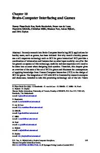
Status Reporting Figure 3 shows the status reporting scheme of the controller. Each of the registers which may be accessed by a command or query has the appropriate command or query written above or below the register representation. For example, the Laser Condition Register may be queried via the LASer:COND? query, as shown by its register heading. The condition or event registers are logically ANDed with their respective enable registers. These bits are then logically ORed to form a summary message in the Status Byte Register for that particular register.
Chapter 1
Computer Interfacing
Standard Event Status Register *ESR? 0 - Operation Complete 7 6 5 4 3 2 1 0 1 - GPIB Parser Idle 2 - Query Error Logical 3 - Device Dependent Error OR 4 - Execution Error 5 - Command Error 7 6 5 4 3 2 1 0 6 - N/A 7 - Power On Standard Event Status Enable Register *ESE *ESE?
7
LASER Condition Status Register 0 - Current Limit 1 - Voltage Limit LASer:COND? 2 - Photodiode Current Limit 15 14 13 12 11 10 9 8 7 6 5 4 3 2 1 0 3 - Power Limit 4 - Interlock Error 5 - N/A 6 - N/A Logical 7 - Open Circuit 8 - Output Shorted OR 9 - Out of Tolerance 10 - Output On 11 - Ready for Calibration Data 15 14 13 12 11 10 9 8 7 6 5 4 3 2 1 0 12 - Calculation Error 13 - Module Communications Error LASER Condition Status Enable Register 14 - Control Software Error 15 - EEPROM Checksum Error LASer:ENABle:COND LASer:ENABle:COND?
(Channels logically ORed)
Queue Not Empty { Output Queue
Queue Not Empty } Error Queue
(Channels logically ORed)
Status Byte Register *STB? Service Request Generation
0 - TEC Event Summary 1 - TEC Condition Summary 2 - LASER Event Summary 3 - LASER Condition Summary Logical 4 - Message Available OR 5 - Event Status Summary 6 - Request Service / Master Status Summary { 7 5 4 3 2 1 0 7 - Error Available Service Request Enable Register *SRE *SRE? {
7 6 5 4 3 2 1 0
Copy of Status Byte Register 15 14 13 12 11 10 9 8
Logical
OR 15 14 13 12 11 10 9 8
ist
7 6 5 4 3 2 1 0
Parallel Poll Enable Register *PRE *PRE?
Logical
OR
0 - TEC Event Summary 1 - TEC Condition Summary 2 - LASER Event Summary 3 - LASER Condition Summary 4 - Message Available 5 - Event Status Summary 6 - Request Service / Master Status Summary 7 - Error Available
0 - Current Limit 1 - Voltage Limit 2 - Photodiode Current Limit 3 - Power Limit 4 - Interlock Error 5 - N/A 6 - N/A 7 - Open Circuit 8 - Output Shorted 9 - Tolerance Status Changed 10 - Output Status Changed 11 - New Measurements 15 14 13 12 11 10 9 8 7 6 5 4 3 2 1 0 12 - Calculation Error 13 - Module Communications Error LASER Event Status Enable Register14 - Control Software Error 15 - EEPROM Checksum Error LASer:ENABle:EVEnt LASer:ENABle:EVEnt? 7 6 5 4 3 2 1 0
0 - Current Limit 1 - Voltage Limit 2 - Resistence Limit 3 - High Temperature Limit 4 - Low Temperature Limit 5 - Shorted Sensor 6 - Open Sensor Logical 7 - Open Module 8 - N/A OR 9 - Out of Tolerance 10 - Output On 11 - Ready for Calibration Data 15 14 13 12 11 10 9 8 7 6 5 4 3 2 1 0 12 - Calculation Error 13 - TEC Interlock TEC Condition Status Enable Register14 - Control Software Error 15 - EEPROM Checksum Error TEC:ENABle:COND TEC:ENABle:COND?
(Channels logically ORed)
7 6 5 4 3 2 1 0
LASER Event Status Register LASer:EVEnt?
15 14 13 12 11 10 9 8
TEC Condition Status Register TEC:COND?
15 14 13 12 11 10 9 8
(Channels logically ORed)
TEC Event Status Register TEC:EVEnt?
0 - Current Limit 1 - Voltage Limit 2 - Resistence Limit 3 - High Temperature Limit 4 - Low Temperature Limit 5 - Sensor Shorted 6 - Sensor Open 7 - Module Open 8 - Sensor Type Change 9 - Tolerance Status Change 10 - Output On/Off Change 11 - New Measurements 15 14 13 12 11 10 9 8 7 6 5 4 3 2 1 0 12 - Calculation Error 13 - TEC Interlock TEC Event Status Enable Register 14 - Control Software Error TEC:ENABle:EVEnt 15 - EEPROM Checksum Error TEC:ENABle:EVEnt? 15 14 13 12 11 10 9 8
Logical
OR
7 6 5 4 3 2 1 0
7 6 5 4 3 2 1 0
Figure 3 - Status Reporting Diagram
1.6.1
Event and Condition Registers The Event Registers are used to report events which occur during the operation of the controller. Events differ from conditions in that events signal an occurrence once, and are not reset until the Event Register is queried or the controller is powered off. Conditions reflect the current state of the device, and therefore may change many times during operation. Querying a Condition Register does not change its contents.
8
Chapter 1
Computer Interfacing
The controller contains Event and Condition Registers for TEC and laser controller operations. It also contains the Standard Event Status Register which reports events for general operation of the controller.
1.6.2
Operation Complete Definition Note that bit 0 of the Standard Event Status Register contains the status of the Operation Complete flag (see *OPC). Enabling this bit via the *ESE command allows the user to update bits of the Status Byte Register. Then, if the Service Request Enable Register (see *SRE) mask has bit 5 set, and the user issues an *OPC command, a service request (SRQ) will be issued upon completion of the currently processed commands. This may be used to initiate service request routines which depend on the completion of all previous commands. For example, the user may set the TEC output to 30°C, enable the SRQ on Operation Complete, and have an SRQ handling routine in the user's software which begins a new measurement after the 30°C value has been reached. This allows the use of the operation complete features of the controller, such as the TOLerance commands, without the need for program looping or polling which can tie up the GPIB. Operation Complete on the controller is defined as: 1) The laser controller, which is updating the current source hardware, is idle. 2) The TEC controller, which is updating the temperature controller hardware, is idle. 3) No EPROM (non-volatile) memory write cycles are in progress. 4) New laser current and photodiode measurements are available, updated approximately every 500 - 1000 milliseconds. 5) New TEC sensor and ITE measurements are available, updated approximately every 500 - 1000 milliseconds. 6) No delay timeout clocks are running. 7) No calibration routines are running.
Chapter 1
Computer Interfacing
9
8) Laser output is off, or it is on and within tolerance. 9) TEC output is off, or it is on and within tolerance.
1.7
Output Off Registers The Output Off Enable Registers allow the user to determine which conditions and events in the TEC and laser controllers will cause their outputs to be turned off. These registers are configured in a manner which is similar to the status reporting registers. However, their outputs are not reported in the Status Byte Register. Rather, they go to the hardware which controls the output switching. The events and conditions which may be set to cause the TEC and laser outputs to be turned off are shown in the tables below. Note that each TEC module and each laser module have their own set of registers. The conditions which are enabled by default are shown in bold.
Laser Output Off Register bit 0 - Laser Current Limit bit 1 - Laser Voltage Limit (always enabled) bit 2 - Photodiode Current Limit bit 3 - Photodiode Power Limit bit 4 - Laser Interlock Error (always enabled) bit 5 - N/A bit 6 - N/A bit 7 - Laser Open Circuit (always enabled) bit 8 - Laser Output Shorted (always enabled) bit 9 - Laser Output Out of Tolerance bit 10 - TEC Output Off Event bit 11 - TEC Temperature Limit Condition bit 12 - Hardware Error bit 13 - N/A bit 14 - N/A bit 15 - N/A
10
Chapter 1
Computer Interfacing
TEC Output Off Register bit bit bit bit bit bit bit bit bit bit bit bit bit bit bit bit
1.8
0 - TEC Current Limit 1 - TEC Voltage Limit 2 - R Limit 3 - High Temperature Limit 4 - Low Temperature Limit 5 - N/A 6 - Sensor Open 7 - TEC Module Open 8 - Sensor Type Change (always enabled) 9 - Out of Tolerance 10 - Sensor Shorted 11 - N/A 12 - Software Error 13 - TEC Interlock2 14 - N/A 15 - N/A
Overview of the Controller Device Dependent Commands There are two types of device commands; 1) commands which cause the controller to do something, and 2) queries which return stored value or state of the instrument. Queries must end with a question mark (?), while commands may require parameter(s) to follow: TEC:GAIN 1 For example, the "1" in the command TEC:GAIN 1, sets the TEC gain at 1. Generally, a command or query is entered (spelled) as shown in Table 2. Upper or lower case may be used in any combination, but the command/query MUST contain all of the letters which are shown in upper case in Table 2. The lower case letters shown with the commands are optional, and may be used for clarity. For example, the following commands are equal. TEC:DIS 1 and tec:DISPLAY 1 and Tec:Disp 1
2
Not supported on all TECs.
Chapter 1
Computer Interfacing
11
The syntax of the controller commands follows the rules laid out in the IEEE-488.2 standard. Colons (:) indicate the start of a new command path, while semicolons (;) indicate a separation of commands within a command string. A leading semicolon on a command may be used to return the controller command parser to the command path root.
1.8.1
Active Laser and TEC Channel The command set of the controller operates on a single channel. However, some controllers operate as a multi-channel devices. For example, there may be a TEC module installed in slots 1 and 2 and a laser module installed in slots 3 and 4. Some commands do not apply to a particular channel, such as BEEP. However, many commands do apply to a specific channel, either a TEC or a laser. When the controller powers up, the active channel for each type of module is the first instance of that module in the system. For example, in an controller with laser modules in slots 1 and 3, and TEC modules in slots 2 and 4, the active laser module would be slot 1, and all laser commands would be directed at that module (unless a LASer:CHANnel switched to module 3). Likewise, the active TEC module on power up would be module 2, and all TEC commands would be directed at that module. See the LASer:CHAN and TEC:CHAN commands for additional details.
1.8.2
Substitute Parameter Names For clarity in programming, the Boolean values of one and zero may also be represented by the appropriate substitute parameter names, as shown below. Substitute Name ON OFF OLD NEW TRUE FALSE
Value 1 0 1 0 1 0
The ON parameter name could be used in place of the 1 in the example as follows: TEC:DIS ON
12
Chapter 1
Computer Interfacing
1.8.3
Compound Command Structure Many of the controller remote commands require a compound structure. For example, commands which deal with the controller TEC have the path TEC:, as in the command to set the TEC high resistance limit: TEC:LIM:RHI 25.000 Table 2 lists all of the controller's device-dependent commands, with the full path shown for each command and a brief explanation of its usage. As shown above, the colon (:) separates commands in a compound command. Compound queries are also valid, such as: LASer:DIS? If multiple parameters are expected, they should be separated with commas. For example, to set the Steinhart-Hart constants on the controller (C1, C2, and C3) the following command could be sent: TEC:CONST 1.111, 2.004, 0.456 Spaces or white space may be placed anywhere in a command string (after the command header or query question mark), and must be used to separate the command from the first parameter. The following examples show valid syntax for commands with the controller. TEC:MODE:t; TEC:T 25; TEC:Const 1, 2, 3.5; TEC:OUT 1 :TEC:DIS 1; tec:set:t? Laser:limit:i 40 LASer:set:ldv? The following are examples of invalid syntax for the controller. These command strings would produce an erroneous result, as explained: TEC:MODE T TEC:MODE:R DEC LASer:DIS ? Las:LDI33;dis?
1.8.4
- Missing colon, MODE? expected - missing semicolon, DEC command generates an error - Space not allowed before question mark, DIS command expected. - Space missing between LDI command and the parameter value, 33.
Advanced Programming Once you have become familiar with the command syntax and structure, you may take advantage of some programming shortcuts which are available.
Chapter 1
Computer Interfacing
13
Due to the "tree-walking" capabilities of the controller software, the user may elect to write command strings without constantly repeating the entire command path for each command.
1.8.5
Path Specification The first command in the string must have its entire path entered. But once a path level is reached, other commands which are at the same level (or higher level) may then be entered without repeating the path. To accomplish this, the semicolon (;) must be used to separate the commands in the string, as usual. However, the command following the semicolon need not specify its full path, if the same path which was previously written out could be used for the new command. For example, the following legal command string could be used to (1) set the controller TEC display to the measured temperature and (2) set the TEC display for the (temperature) set point value: TEC:LIMit:THI 50;SET The path TEC:LIMit: is "remembered" by the controller software in this case. If the SET command were not found at this level, the software would walk back to the TEC: level and search for a TEC:SET command. If it is not found there, it will search at the next higher level, and so on until it finds the command or not. If the command is not found, an error message will be generated. The following is an example of command "tree-walking", where (1) the laser display is set for the current set point, and (2) the laser output is turned on: Laser:enable:cond?; out on The command out is first searched at the LASer:ENABle: level. Since the command LASer:ENABle:OUT does not exist, the next higher level LASer: is searched. There the command LASer:OUT is found, and the parameter on is legal, so there is no error. Care must be taken to avoid errors which are caused by trying to implement commands from the wrong path or level. For example, the following command string was intended to (1) read back the set point resistance and (2) read back the measured resistance:
14
Chapter 1
Computer Interfacing
TEC:SET:R?; R? Instead, the output would return the set point resistance twice. When the second R? is found, the software will first search for that command at its current level. Since it finds it there it will be executed. If this command did not exist at this level, the software would search up to the TEC: level and find and execute the intended command, TEC:R?. In order to ensure the proper command is executed for the example above, the following command string should be issued: TEC:SET:R?; TEC:R? If you are not sure of the path level of a command, refer to the controller Command Path Structure diagram shown in Figure 4. For this discussion, the root level is the highest level, and moving down the diagram decreases the level. Once the software has "walked" to a lower path level, it remains at that level when it receives the next command. For example, to (1) set the laser display to show the set point, (2) decrement the set point, and (3) set the TEC high temperature limit, the following command string could be used: LASer:LIM:LDV?; DEC; TEC:LIM:THI 50 When the DEC command is reached, the software is at the LASer:LIMit: level. Since there is no DEC command there, it walks back up to the LAS level, and there it finds the LASer:DEC command. The reason that the full path (including TEC:) must be specified for the last part (TEC:LIMit:THI) is that otherwise it would look for the LIM:THI command in the LASer: path, not find it, and generate an error. After the second semicolon is reached (DEC;) the software will first look for the next word (TEC) at the current path. Since it is not found it will walk back up the tree until it finds it at the root level. Once the search walks up to the root level, it will not walk down any other paths, unless the path is specified. The only exception to the rule described above is when common commands are used. In that case, the software remembers which level the user was at before the common command was found, and it returns to that same level
Chapter 1
Computer Interfacing
15
after finding and executing the common command. Therefore the following command string is legal: TEC:LIM:THI 50; *WAI;DEC Here, (1) the high temperature limit is set to 50, (2) the software waits for the previous command to be executed, and (3) the set point is decremented one step. root
LINK *CAL? *CLS *ESE *ESE? *ESR? *IDN? *IST? *OPC *OPC? *PRE *PSC *PSC? *RCL *RST *SAV *SRE *SRE? *STB? *TST *WAI
BEEP BEEP? BRIGHT BRIGHT? CONTRAST CONTRAST? DELAY ERRors? EQUIPment? INVERT INVERT? LOCAL ONDELAY ONDELAY? MASTER MASTER? MEM? MESsage MESsage? RADix RADix? RMTERR RMTERR? TERM TERM? TERMINAL TERMINAL? TIME? TIMER?
ALL? CLEAR CLEARALL GET? SET
TEC
LASer
CALMD CALMD? CHAN CHAN? COND? DEC DIS DIS? EVE? INC LDI LDI? LDV LDV? MDI MDI? MDP MDP? MODE? OUT OUT? STB? STEP STEP? TOL TOL?
CAL
ENAB
LIM
MODE
SET
LDI LDI? LDV LDV? MDI MDI?
COND COND? EVE EVE? OUTOFF OUTOFF?
LDI LDI? MDI MDI? MDP MDP?
IHBW ILBW MDI MDP
LDI? MDI? MDP?
CHAN CHAN? COND CONST CONST? DEC DIS DIS? EVE? GAIN GAIN? INC ITE ITE? MODE? OUT OUT? R R? SEN SEN? STB? STEP STEP? T T? TOL TOL?
CAL
ENAB
LIM
ITE ITE? SEN SEN?
COND COND? EVE EVE? OUTOFF OUTOFF?
ITE ITE? RLO RLO? RHI RHI? TLO TLO? THI THI?
MODE ITE R T
SET ITE? R? T?
Figure 4 - Command Path Structure
1.8.6
Timing Considerations Although the shortcuts mentioned above reduce the command length, they may not necessarily optimize the speed of program execution. The following tip may be useful if speed of execution of a command is critical. If a command follows a semicolon (;) in a command string, and it is not at the root level, using the colon (:) will aid the software in locating the command, and time will be saved. For example, the following command string will execute slightly faster as shown than it would if the first colon (:) after the second semicolon (;) was not included. This would save the time of two binary searches, one at the LASer:DEC level and one at the LASer: level.
16
Chapter 1
Computer Interfacing
LASer:SET:LDV?;DEC;TEC:SET:T? In other cases, the hardware may not be able to react as quickly as the commands are executed. For example, if the set point is greatly incremented (i.e. by 10°C) and a measurement is taken before that new set-point temperature has been reached, the measurement could be invalid due to a premature measurement. For cases like this, the *WAI command is useful. The *WAI command will suspend the execution of the next command until the previous command has been completed.
1.9
ILX Lightwave Corporation LDC-3900 and LDC-3700 Users The following is a listing of changes that need to be addressed if you are switching from the ILX LDC-3900 or LDC-3700 system to the Newport Corporation controller system or when using both. 1. TEC Sensor Type The sensor type on the ILX unit is selected by a switch on the rear panel. On the Model controller the TEC:SENS command is used to select the sensor in software. 2. TEC Loop Gain The TEC:GAIN command contains two additional settings (5 and 50) that the ILX 3900 does not support. 3. Additional Commands Available Laser LASer:CAL:CANCEL LASer:LIMit:MDI LASer:LIMit:MDI? LASer:LIMit:LDV LASer:LIMit:LDV? LASer:MODE:ICW LASer:MODE:MDI
TEC TEC:CAL:CANCEL TEC:LIMit:TLO TEC:LIMit:TLO? TEC:LIMit:RHI TEC:LIMit:RHI? TEC:LIMit:RLO TEC:LIMit:RLO? TEC:SENSor
4. Unsupported Commands These commands are not supported. The controller controller will accept them without error, but will not act on them. All queries will return “0”.
Chapter 1
Computer Interfacing
17
General *DLF *PUD *PUD? Laser LASer:DISplay:xxx commands
TEC TEC:DISplay:xxx commands
5. Additional Conditions/Events Available Laser Photodiode Current Limit
TEC R Limit Low Temp Limit Sensor Shorted TEC Interlock3
6. TEC Booster and Interlock The controller's TEC does not support any of the ILX booster or interlock functions. Note also that their respective bits in the event and condition registers have been redefined.
3
Not supported on all TECs.
C H A P T E R
2.
2
Commands and Queries Table 2 summarizes all the commands and queries. Note: For compatibility, some commands have optional entries; such as LASer:LDI, which can also be LASer:I. Options are shown in Table 2 as parenthesis; such as LASer:LDI (I). After Table 2, each command and query is detailed. Table 2 - GPIB/RS-232 Command Summary
Name
Number of Parameters
Function
IEEE 488.2 Commands/Queries
*CAL? *CLS *ESE *ESE? *ESR? *IDN? *IST? *OPC *OPC? *PRE *PRE? *PSC *PSC? *RCL *RST *SAV *SRE *SRE? *STB? *TST? *WAI
NONE NONE 1 NONE NONE NONE NONE NONE NONE 1 NONE 1 NONE 1 NONE 1 1 NONE NONE NONE NONE
Calibration command/query Clear status command Event status register enable command Event status register enable query Event status register query Identification query Individual status query Operation complete command Operation complete query Parallel poll enable register command Parallel poll enable register query Power-on status clear command Power-on status clear query Recall saved bin command Reset command Save bin command Service request enable command Service request enable query Status byte register query Self test query Wait for operation complete command
Device Dependent Commands/Queries BEEP BEEP? BRIGHT BRIGHT? CONTRAST CONTRAST? DELAY
1 NONE 1 NONE 1 NONE 1
Turns the beeper on or off, or beeps once. Returns the status of the beeper. Change display brightness Get display brightness Change display contrast Get display contrast Used to create a delay in the execution of further commands.
20
Chapter 2
Commands and Queries
ERRors? ERRSTR?
NONE NONE
EQUIPment? INVERT INVERT? LASer:CALMD (CALPD) LASer:CALMD? (CALPD?) LASer:CAL:CANCEL
NONE 1 NONE 1 NONE
LASer:CAL:LDI (I) LASer:CAL:LDI? (I?)
1 NONE
LASer:CAL:LDV LASer:CAL:LDV?
NONE NONE
LASer:CAL:MDI (IPD)
NONE
LASer:CAL:MDI? (IPD?)
NONE
LASer:CHAN LASer:CHAN? LASer:COND? LASer:DEC
NONE
1 or 2 NONE NONE 0, 1, or 2
LASer:DISplay LASer:DISplay? LASer:ENABle:COND LASer:ENABle:COND?
1 NONE 1 NONE
LASer:ENABle:EVEnt LASer:ENABle:EVEnt? LASer:ENABle:OUTOFF
1 NONE 1
LASer:ENABle:OUTOFF? LASer:EVEnt? LASer:LDI (I)
NONE NONE 1
LASer:LDI? (I?)
NONE
LASer:INC LASer:MDI (IPD)
0, 1, or 2 1
LASer:MDI? (IPD?)
NONE
LASer:LDV LASer:LDV?
1 NONE
Returns errors generated since the last query. Returns errors and their corresponding error text generated since the last query. Returns a list of modules installed in the 6000 Invert the display Get display insert setting Used to set the CALPD (Sensitivity) constant. Returns the CALPD (Sensitivity) constant. Cancels calibration without updating calibration constants. Used to set the constant I calibration constant. Returns the ready state for entering the constant I calibration value. Used to enter the laser voltage calibration mode. Returns the ready state for entering the laser voltage calibration value. Used to set the photodiode feedback current calibration constant. Returns the ready state for entering the IPD calibration value. Used to select the LAS channel , subchannel. Returns the number of the LAS selected channel. Returns the value of the LAS condition register. Used with LASer:STEP command to decrement the set point value by one step, when no parameters are used. Optional parameters are for number of steps and number of milliseconds between steps. Turns the LAS display on or off. Returns the LAS display value. Sets the enable register for LAS conditions. Returns the value of the LAS conditions enable register. Sets the enable register for LAS events Returns the value of the LAS event enable register. Sets the enable register for LAS conditions which turn the LAS output off. Returns the value of the LAS outoff enable register. Returns the value of the LAS event register. Used to set the LAS constant current source set point value. Used to return the constant current source measured value (measured about every 400mS). Used with LASer:STEP command to increment the LAS set point value (see LASer:DEC). Used to set the constant optical power set point if PD sensitivity is 0. Used to return the monitor PD current measured value (measured about every 400 milliseconds). Used to set the voltage value for calibration. Used to return measured laser voltage value (measured about every 400 milliseconds).
Chapter 2
LASer:LIMit:LDI (I) LASer:LIMit:LDI? (I?) LASer:LIMit:LDV LASer:LIMit:LDV? LASer:LIMit:MDI (IPD) LASer:LIMit:MDI? (IPD?) LASer:LIMit:MDP (Ppd)
Commands and Queries
1 NONE 1 NONE 1 NONE 1
LASer:LIMit:MDP? (Ppd?)
NONE
LASer:MODE?
NONE
LASer:MODE:ICW LASer:MODE:ILBW (I)
NONE NONE
LASer:MODE:IHBW
NONE
LASer:MODE:MDI (IPD) LASer:MODE:MDP (Ppd) LASer:MODULATE LASer:MODULATE? LASer:OUT LASer:OUT? LASer:MDP (Ppd)
NONE NONE 1 NONE 1 NONE 1
LASer:MDP? (Ppd?)
NONE
LASer:SET:LDI? (I?) LASer:SET:MDI? (IPD?)
NONE NONE
LASer:SET:MDP? (Ppd?)
NONE
LASer:STB?
NONE
LASer:STEP
1
LASer:STEP? LASer:TOLerance
NONE 2
LASer:TOLerance?
NONE
LINK:ALL? LINK:CLEAR LINK:CLEARALL LINK:GET LINK:SET
NONE 1 NONE 1 4
21
Used to set the laser constant current source limit. Used to return the laser constant current source limit. Used to set the laser compliance voltage Used to return the laser compliance voltage Used to set the laser monitor photodiode current limit. Used to return the laser monitor photodiode current limit. Used to set the constant optical power (from monitor PD) limit value. Used to return the optical power (from monitor PD) limit value. Returns the mode, I (current), IHBW (current, high bandwidth) PPD (optical power) Ipd or Icw (cont. wave). Sets the Laser to continuous wave mode. Sets the Laser to constant current (low bandwidth) mode. Sets the Laser to constant current, high bandwidth mode. Sets the Laser to constant photodiode current mode. Sets the Laser to constant optical power mode. Selects the MOPA modulation channel Returns the MOPA modulation channel Same action as setting the LAS OUTPUT on/off. Returns the LAS OUTPUT status. Used to set the constant optical power set point, if PD sensitivity is non-zero. Returns the actual monitor PD power value (measured about every 400 milliseconds). Returns the constant I (current) set point. Returns the constant optical power set point, if the PD sensitivity is 0. Returns the constant P (optical power) set point, if the PD sensitivity is non-zero. Returns the status summaries for conditions and events. Used to set the LAS step value for use with DEC or INC commands. Defaults to a step of 1; 1-step = 0.01 mA (I or IHBW mode), 0.01 mW (P mode), or 1 uA (if CALPD = 0). Range is 1 - 9999 steps. Returns the LAS step value. Used to set the LAS set point tolerance value and time period to determine if a set point has been reached. Used to return the LAS set point tolerance value and time period used to determine if a set point has been reached within the time period. Returns a list of links in the system. Clears a single link. Clears all links in the system. Returns a specific link. Defines a new link.
22
Chapter 2
Commands and Queries
LOCAL ONDELAY ONDELAY? MASTER MASTER? MESsage MESsage? RADix
NONE 1 NONE NONE NONE 1 NONE 1
RADix? REMERR
NONE 1
REMERR?
NONE
TEC:CAL:CANCEL
NONE
TEC:CAL:ITE
NONE
TEC:CAL:ITE?
NONE
TEC:CAL:SEN TEC:CAL:SEN?
NONE NONE
TEC:CHAN TEC:CHAN? TEC:COND? TEC:CONST
1 or 2 NONE NONE 1-3
TEC:CONST?
NONE
TEC:DEC
NONE
TEC:DIS TEC:DIS? TEC:ENABle:COND TEC:ENABle:COND?
1 NONE 1 NONE
TEC:ENABle:EVEnt TEC:ENABle:EVEnt? TEC:ENABle:OUTOFF
1 NONE 1
TEC:ENABle:OUTOFF? TEC:EVE? TEC:GAIN TEC:GAIN? TEC:INC
NONE NONE 1 NONE NONE
TEC:ITE TEC:ITE?
1 NONE
Return to local mode, RS-232 only. Set the laser turn-on delay Get the laser turn-on delay Switch to the master display Returns 1 if in master display, 0 otherwise. Used to enter a string message of up to 16 bytes. Returns a previously stored message. Used to set a radix type for numerical data. Decimal, binary, octal and hexadecimal are allowed. Used to return the radix type for numerical data. Used to enable/disable the display of errors on the unit’s screen when in remote mode. Returns 1 if display errors while remote is disabled, 0 otherwise. Cancels calibration without updating calibration constants. Used to set the TEC current source calibration constants. Returns the ready state for entering a current source calibration value. Used to set a sensor calibration constant. Returns the ready state for entering a sensor calibration value. Used to select the TEC channel , subchannel. Returns the number of the selected TEC channel. Returns the value of the TEC condition register. Used to enter the Steinhart-Hart constants for R-T conversion. Also used to enter constants for AD590, LM335 and RTD. Used to read back the Steinhart-Hart constants for RT conversion. Also used to read back constants for AD590, LM335 and RTD. Used with TEC:STEP command to decrement the TEC set point value by one step. Turns the TEC display on or off. Returns the TEC display value. Sets the enable register for TEC conditions. Returns the value of the TEC condition enable register. Sets the enable register for TEC events. Returns the value of the TEC event enable register. Sets the enable register for TEC conditions which turn the TEC output off. Returns the value of the TEC outoff enable register. Returns the value of the TEC event register. Used to set the TEC control loop gain. Used to return the TEC control loop gain. Used with TEC:STEP command to increment the TEC set point value by one step. Used to set the TEC current (ITE) set point. Returns the measured TEC current (ITE) value (measured about every 400 milliseconds).
Chapter 2
Commands and Queries
TEC:LIM:ITE TEC:LIM:ITE? TEC:LIM:RHI TEC:LIM:RHI? TEC:LIM:RLO TEC:LIM:RLO? TEC:LIM:THI TEC:LIM:THI? TEC:LIM:TLO TEC:LIM:TLO? TEC:MODE?
1 NONE 1 NONE 1 NONE 1 NONE 1 NONE NONE
TEC:MODE:ITE TEC:MODE:R
NONE NONE
TEC:MODE:T TEC:OUT TEC:OUT? TEC:R TEC:R?
NONE 1 NONE 1 NONE
TEC:SEN TEC:SEN? TEC:SET:ITE? TEC:SET:R?
1 NONE NONE NONE
TEC:SET:T? TEC:STB?
NONE NONE
TEC:STEP
1
TEC:STEP? TEC:T
NONE 1
TEC:T? TEC:TOL
NONE 2
TEC:TOL?
NONE
TEC:V? TERM TERM? TERMINAL
NONE 1 NONE 1
TERMINAL?
NONE
23
Used to set the TEC constant current source limit Used to return the constant current source limit. Used to set the TEC high resistance limit. Returns the TEC high resistance limit. Used to set the TEC low resistance limit. Returns the TEC low resistance limit. Used to set the TEC upper temperature limit. Returns the TEC upper temperature limit. Used to set the TEC low temperature limit. Returns the TEC low temperature limit. Returns the mode, ITE (TEC current), R (resistance/reference) or T (temperature). Sets to constant TEC current mode. Sets to constant thermistor resistance/linear sensor reference mode. Sets to constant temperature mode. Same action as setting the TEC OUTPUT on/off. Returns the TEC OUPUT status. Sets the constant R (resistance/reference) set point. Returns the measured R (resistance/reference) value (measured about every 400 milliseconds). Selects the sensor type. Returns the sensor type. Returns the constant ITE (TEC current) set point. Returns the constant R (resistance/reference) set point. Returns the constant T (temperature) set point. Returns the status summaries for conditions and events. Used to set the TEC step value for use with DEC or INC commands. Defaults to a step of 1. 1 step equals 0.1°C, 1 mA (ITE), 1 Ohm (Therm), 0.1 mV, (LM335) 0.01 µA (AD590) or .01 Ω (RTD). Range is 1 - 9999 steps. Returns the value of the TEC step. Used to set the TEC constant T (temperature) set point. Returns the TEC measured temperature value Used to set the TEC set point tolerance value and time period used to determine if a set point has been reached. Used to return the TEC set point tolerance value and time period used to determine if a set point has been reached. Returns the TEC measured voltage value Sets the response message terminator. Returns the value of the response message terminator. Enabled/disabled terminal mode for RS-232C connection. Returns 1 if the RS-232C terminal mode is enabled.
24
Chapter 2
Commands and Queries
TIME?
NONE
TIMER?
NONE
Returns the elapsed time since the 6000 was last powered on. Returns the elapsed time since the timer was last reset.
Chapter 2
2.1
Commands and Queries
25
IEEE 488.2 Common Commands and Queries This section contains a list of the common commands and queries which are supported by the controller. The common commands and queries are distinguished from device dependent types by the * which begins each one. The common commands and queries are listed in alphabetical order, and a brief description of their functions is given. Refer to Figure 3 for commands that deal with status. 3150 3040 5000 6000 8000 8008 9000 9 9 9 9 9 9 9
*CAL? Description
Calibration query.
Syntax
*CAL?
Remarks
When this query is sent, the controller performs the TEC and laser controller's ADC and DAC calibration procedure and reports the status. Response
Description
=0 ≠0
no calibration errors calibration errors detected 3150 3040 5000 6000 8000 8008 9000 9 9 9 9 9 9 9
*CLS Description
Clear status command.
Syntax
*CLS
Remarks
It is used to clear the Status Byte Register and all event registers. It may be used, for example, to clear the Event Status Register, the Standard Event Status Register, and the error queue before enabling SRQ generation from instrument events. The *CLS command also cancels any outstanding *OPC and *OPC? commands.
See Also
ESR?, ERR?, *IST?, *STB? 3150 3040 5000 6000 8000 8008 9000 9 9 9 9 9 9 9
*ESE Description
Event Status Register Enable command.
Syntax
*ESE mask
26
Chapter 2
Commands and Queries
Remarks
This command enables the Standard Event Status Register to update bit 5 of the Status Byte Register. See the table under the ESR? command for a definition of the ESE bits. The parameter value may indicate multiple conditions, i.e. 5 is both bit 2 and 0. Setting bit 0 allows the user to poll or generate SRQ from any overlapped commands after any previous operations are completed. This may be useful for ensuring that an operation, such as TEC output on and within tolerance, is complete before a measurement is made. Although this could be performed without using service requests, an interrupt-driven program makes more efficient use of the GPIB than polling or waiting (*WAI) routines.
See Also
*ESE?, *ESR?, *STB 3150 3040 5000 6000 8000 8008 9000 9 9 9 9 9 9 9
*ESE? Description
Event Status Register Enable query.
Syntax
*ESE?
Remarks
This query will cause the controller to return the value of the Standard Event Enable Register. This allows the user to determine which status bits can set the summary bit (bit 5) in the Status Byte Register. See the table under the ESR? command for a definition of the ESE? bits. The response may indicate multiple conditions, i.e. 5 is both bit 2 and 0.
See Also
*ESE, *ESR?, *STB 3150 3040 5000 6000 8000 8008 9000 9 9 9 9 9 9 9
*ESR? Description
Event Status Register query.
Syntax
ESR?
Remarks
This query will cause the controller to return the value of the Standard Event register. This allows the user to determine which type of error has occurred, for example.
Chapter 2
Response
ESR
Commands and Queries
Bit Value
0
1
1
2
2
4
3
8
4
16
5
32
6 7
64 128
27
Description
Operation Complete: All commands prior to and including an *OPC command have been executed. GPIB Parser Idle: The GPIB parse buffer is empty. However, a *OPC, *OPC?, *WAI, DELAY, or laser/TEC step function may still be running. Query Error: Input or output buffers are full (see error numbers 300 through 399) Device Dependent Error: A self-test, calibration, or other module specific error (see error numbers 400 through 599) Execution Error: An execution error occurred (see error numbers 200 through 299) Command Error: A command error occurred (see error numbers 100 through 199) N/A Power On: Power has been turned off and on since the last time the event register was read or cleared.
The response may indicate multiple conditions, i.e. 5 is both bit 2 and 0. See Also
*ESE, *STB 3150 3040 5000 6000 8000 8008 9000 9 9 9 9 9 9 9
*IDN? Description
Identification query.
Syntax
*IDN?
Remarks
This query will cause the controller to return an identification string. Response
IDN String
Value
Description
“Newport XXXX vY.YY BZZ”, where XXXX is the product platform (3000, 5000, etc.), X.XX is the version number and YY is the build number. 3150 3040 5000 6000 8000 8008 9000 9 9 9 9 9 9 9
*IST? Description
Individual status query.
Syntax
*IST?
28
Chapter 2
Remarks
The Individual Status query allows the user to read the current state of the IEEE-488.1 'ist' local message.
See Also
Commands and Queries
Response
Description
ist bit
0 1
ist false ist true
*PRE, *STB 3150 3040 5000 6000 8000 8008 9000 9 9 9 9 9 9 9
*OPC Description
Operation Complete command
Syntax
*OPC
Remarks
This *OPC command causes the controller to generate the operation complete message in the Standard Event Status Register when all pending overlapped commands have been completed. The operation of this command is identical to *WAI, except *WAI does not generate a response.
See Also
*OPC?, *ESR?, *WAI 3150 3040 5000 6000 8000 8008 9000 9 9 9 9 9 9 9
*OPC? Description
Operation Complete query.
Syntax
*OPC?
Remarks
This query places an ASCII character into the controller's Output Queue when all pending operations have been finished. The operation of this command is identical to *WAI, except *WAI does not generate a response.
See Also
Response
Description
1
finished
*OPC, *WAI 3150 3040 5000 6000 8000 8008 9000 9 9 9 9 9 9 9
*PRE Description
Parallel Poll Enable Register command
Syntax
*PRE mask
Remarks
This command sets the Parallel Poll Enable Register bits. These bits are defined the same as the SRE register.
Chapter 2
Commands and Queries
Argument
Bit
Value Description
mask
0 1 2 3 4 5 6 7 8 9 10 11 12 13 14 15
1 2 4 8 16 32 64 128 256 512 1024 2048 4096 8192 16384 32768
29
TEC Event Summary TEC Condition Summary Laser Event Summary Laser Condition Summary Message Available Event Status Summary Master Status Summary Error Message Available N/A N/A N/A N/A N/A N/A N/A N/A
The parameter may indicate multiple conditions, i.e. 5 is both bit 2 and 0. See Also
*PRE?, *STB, *SRE 3150 3040 5000 6000 8000 8008 9000 9 9 9 9 9 9 9
*PRE? Description
Parallel Poll Enable Register query.
Syntax
*PRE?
Remarks
This query allows the programmer to determine the contents of the Parallel Poll Enable Register. See *PRE for a definition of the returned bits.
See Also
*PRE 3150 3040 5000 6000 8000 8008 9000 9 9 9 9 9 9 9
*PSC Description
Power-On Status Clear command.
Syntax
*PSC enable
Remarks
The Power-on Status Clear command controls the automatic power-on clearing of the Service Request Enable Register, the Standard Event Status
30
Chapter 2
Commands and Queries
Enable Register, the Event Status Enable Register, the Condition Status Enable Register and the Parallel Poll Enable Register. Argument
enable
Description
0
1
The power-on-status-clear flag of the controller is set FALSE, therefore allowing SRQ (interrupts) to be asserted after power-on. The power-on-status-clear flag of the controller is set TRUE, therefore disallowing SRQ (interrupts) to be asserted after power-on.
When the *PSC 1 command is sent, the controller will clear the above mentioned enable registers (set them all to 0) at power-up. This may be done to avoid any undesirable service requests after a power on/off cycle of the controller. The factory default value for this bit is 0, Power-on Status Clear is disabled. Therefore, the values of the enable registers are restored from their condition at the last power-down when a power-up occurs. See Also
*PSC? 3150 3040 5000 6000 8000 8008 9000 9 9 9 9 9 9 9
*PSC? Description
Power-On Status Clear query.
Syntax
*PSC?
Remarks
The Power-on Status Clear Query allows the programmer to query the controller power-on-status-clear flag. Response
PSC Flag
Description
0
1 See Also
*PSC
Standard Event Status Enable Register, Service Request Enable Register, the Event Status Enable Register, the Condition Status Enable Register, and the Parallel Poll Enable Register will retain their values when power is restored to the controller. Registers listed above will be cleared when power is restored to the controller.
Chapter 2
Commands and Queries
31
3150 3040 5000 6000 8000 8008 9000 9 9 9 9 9 9 9
*RCL Description
Recall command.
Syntax
*RCL bin
Remarks
The recall command restores the controller to the setup state which is in its local memory. The following criteria are restored when the *RCL command is given: 1. The controller is in the parameter state which was last stored in that bin. 2. The outputs (laser and TEC) are all off. Argument
Description
bin
0 n
recall reset state recall state n
A value of 0 means the recalled state shall be the same as that of a *RST command. Depending on the platform, up to 11 different stored recall states can be used. These recall states are saved by using the *SAV command. If a different module configuration exists now as compared to when the *SAV command was used, *RCL will not work and will generate an error code. Links are not affected by the recall command. See Also
*RST, *SAV 3150 3040 5000 6000 8000 8008 9000 9 9 9 9 9 9 9
*RST Description
Reset command.
Syntax
*RST
Remarks
The reset command performs a device reset. This has the same effect as *RCL 0 but with the controller OCIS and OQIS idle states set. The GPIB will remain in remote.
32
Chapter 2
Commands and Queries
The Operation Complete Command Idle State (OCIS) is the state which the controller is in when it is no longer waiting for any operation to complete, after an *OPC command has been executed. The Operation Complete Query Idle State (OQIS) is the state which the controller is in when it is no longer waiting for any operation to complete, after an *OPC? query has been executed. These idle states allow the controller to complete its reset process (and have no operations pending) before continuing with any other commands after the *RST is executed. Links are cleared by the reset command. See Also
*RCL 3150 3040 5000 6000 8000 8008 9000 9 9 9 9 9 9 9
*SAV Description
Save command.
Syntax
*SAV bin
Remarks
The save command stores the current state of the controller in non-volatile local memory. A particular state is then recalled by using the *RCL recall command. Depending on the platform, up to 10 unique states can be stored. Argument
Description
bin
Store state bin
Links are not stored. See Also
*RCL 3150 3040 5000 6000 8000 8008 9000 9 9 9 9 9 9 9
*SRE Description
Service Request Enable command.
Syntax
*SRE mask
Remarks
The Service Request Enable command sets the Service Request Enable Register bits to allow the controller to generate the user-selectable service requests. mask is an integer in the range 0 to 255 inclusive.
Chapter 2
Commands and Queries
Argument
Description
mask
bit 0 bit 1 bit 2 bit 3 bit 4 bit 5 bit 6 bit 7
33
TEC Event Summary1 TEC Condition Summary1 Laser Event Summary2 Laser Condition Summary2 Message Available Event Status Summary Request Service/Master Status Summary Error Message Available
The parameter value may indicate multiple conditions, i.e. 5 is both bit 2 and 0. See Also
*SRE? 3150 3040 5000 6000 8000 8008 9000 9 9 9 9 9 9 9
*SRE? Description
Service Request Enable query.
Syntax
*SRE?
Remarks
The Service Request Enable query allows the user to determine the current contents of the Service Request Enable Register. Response
Description
SRE mask
bit 0 bit 1 bit 2 bit 3 bit 4 bit 5 bit 6 bit 7
TEC Event Summary1 TEC Condition Summary1 Laser Event Summary2 Laser Condition Summary2 Message Available Event Status Summary Request Service/Master Status Summary Error Message Available
The response may indicate multiple conditions, i.e. 5 is both bit 2 and 0. See Also
1 2
*SRE
Off for non-TEC units. Off for non-Laser units.
34
Chapter 2
Commands and Queries 3150 3040 5000 6000 8000 8008 9000 9 9 9 9 9 9 9
*STB? Description
Status Byte Register query.
Syntax
*STB?
Remarks
The Read Status Back query allows the programmer to read the Status Byte Register. Response
Description
Status Byte Register bit 0 bit 1 bit 2 bit 3 bit 4 bit 5 bit 6 bit 7
TEC Event Summary1 TEC Condition Summary1 Laser Event Summary2 Laser Condition Summary2 Message Available Event Status Summary Request Service/Master Status Summary Error Message Available
Bit 6 represents the MSS (Master Summary Status) bit and not the RQS message. The response may indicate multiple conditions, i.e. 5 is both bit 2 and 0. See Also
*SRE, *PRE, *IST 3150 3040 5000 6000 8000 8008 9000 9 9 9 9 9 9 9
*TST? Description
Self test query.
Syntax
*TST?
Remarks
The self test query causes an internal self test and returns a response when the self test is complete. Response
Description
=0 ≠0
self test successful self test failed 3150 3040 5000 6000 8000 8008 9000 9 9 9 9 9 9 9
*WAI Description
Wait to continue command
Syntax
*WAI
Chapter 2
Commands and Queries
35
Remarks
The Wait to Continue command prevents the controller from executing any further commands until the Operation Complete flag is true. This allows the programmer to make the controller wait for the completion of an operation before continuing. For example, after a change in temperature is made the *WAI command may be used before a measurement is taken. This would allow time for the correct temperature to be reached.
See Also
*OPC, *OPC?
36
Chapter 2
Commands and Queries
2.2
Device Dependent Commands and Queries. 3150 3040 5000 6000 8000 8008 9000 9 9 9 9 9 9 9
BEEP Description
Beep command
Syntax
BEEP beep set
Remarks
The BEEP command controls the controller beeper. The beeper can be used to signal error or warning conditions.
See Also
Response
Value Description
beep set
0 1 2
Beeper off Beeper on Test beeper
BEEP? 3150 3040 5000 6000 8000 8008 9000 9 9 9 9 9 9 9
BEEP? Description
Beep query
Syntax
BEEP?
Remarks
The BEEP? query returns the enable status of the controller beeper.
See Also
Response
Description
beep set
0 1
Beeper off Beeper on
BEEP 3150 3040 5000 6000 8000 8008 9000 9 9 9 9 9 9 9
BRIGHT Description
Display brightness command
Syntax
BRIGHT brightness
Remarks
The BRIGHT command controls the brightness of the controller display.
See Also
Argument
Description
brightness
Brightness, in percentage, from 0% to 100%
BRIGHT?, CONTRAST
Chapter 2
Commands and Queries
3150 3040 5000 6000 8000 8008 9000 9 9 9 9 9 9 9
BRIGHT? Description
Display brightness query
Syntax
BRIGHT?
Remarks
The BRIGHT? query returns the display brightness setting.
See Also
Response
Description
brightness
Display brightness, in percentage.
BRIGHT 3150 3040 5000 6000 8000 8008 9000 9 9 9 9 9 9 9
CONTRAST Description
Display contrast command
Syntax
CONTRAST contrast
Remarks
The CONTRAST command controls the contrast of the controller display.
See Also
Argument
Description
contrast
Contrast, in percentage, from 0% to 100%
CONTRAST?, BRIGHT 3150 3040 5000 6000 8000 8008 9000 9 9 9 9 9 9 9
CONTRAST? Description
Display contrast query
Syntax
CONTRAST?
Remarks
The CONTRAST? query returns the display contrast setting.
See Also
37
Response
Description
contrast
Display contrast, in percentage.
BRIGHT 3150 3040 5000 6000 8000 8008 9000 9 9 9 9 9 9 9
DELAY Description
Delay command
Syntax
DELAY time
38
Chapter 2
Commands and Queries
Remarks
The DELAY command causes the execution of commands to be delayed by a user-defined time. Response
Description
time
delay in milliseconds
The Operation-Complete flag is held false until the delay period elapses, and the *OPC? query will not execute until the delay period has elapsed. See Also
*OPC, *OPC?, *WAI 3150 3040 5000 6000 8000 8008 9000 9 9 9 9 9 9 9
EQUIPment? Description
Installed equipment query.
Syntax
EQUIPment?
Remarks
The EQUIPment? query returns a list of modules, separated by commas, installed in the controller. A total of five elements are sent: main, module1, module2, module3, module4. If a nothing is installed in a particular module slot, then the corresponding entry is blank.
Examples
Response
Description
Equipment list
Comma-delimited list of equipment
An controller with a 8350 in slot 1, a 8560 in slot 3, and a 8325D in slot 4 would respond to an equipment query with the following response: “controller,8350,,8560,8325D” 3150 3040 5000 6000 8000 8008 9000 9 9 9 9 9 9 9
ERRors? Description
Error query.
Syntax
ERRors?
Remarks
The ERRors? query returns a list of commands and device errors which have occurred since the last query. These errors are indicated by a number that corresponds to the type of error which occurred.
See Also
Response
Description
Error code
Error code number per chapter 5, 0 if no errors
ERRSTR?
Chapter 2
Commands and Queries
39
3150 3040 5000 6000 8000 8008 9000 9 9 9 9 9 9 9
ERRSTR? Description
Error string query.
Syntax
ERRSTR?
Remarks
The ERRSTR? query returns a list of commands and device error numbers along with the corresponding error text strings which have occurred since the last query.
See Also
Response
Description
Error code, “text”
Error code and text for error code as per chapter 5, 0 if no errors
ERRors? 3150 3040 5000 6000 8000 8008 9000 9 9
INVERT Description
Invert the display.
Syntax
INVERT invert
Remarks
On graphical units, the pixels can be reversed to create an inverted display. Argument
Description
invert
0 for normal operation, 1 for inverted operation 3150 3040 5000 6000 8000 8008 9000 9 9
INVERT? Description
Display invert query.
Syntax
INVERT?
Remarks
The INVERT? query returns the current invert state of the display.
LASer:
Response
Description
invert
0 for normal operation, 1 for inverted operation 3150 3040 5000 6000 8000 8008 9000 9 9 9 9 9
The LASer: command path is used to get to the controller laser current source commands. The following command paths may be reached from the LASer: command path:
40
Chapter 2
Commands and Queries
LASer:CAL: LASer:DISplay: LASer:ENABle: LASer:LIMit: LASer:MODE: LASer:SET: The following commands may be reached directly from the LASer: command path. LASer:CALMD LASer:CALMD? LASer:CHAN LASer:CHAN? LASer:COND? LASer:DEC LASer:DISplay LASer:DISplay? LASer:EVEnt? LASer:LDI LASer:LDI? LASer:INC LASer:MDI LASer:MDI? LASer:LDV LASer:LDV? LASer:MODE? LASer:OUTput LASer:OUTput? LASer:MDP LASer:MDP? LASer:STB? LASer:STEP LASer:STEP? LASer:TOLerance LASer:TOLerance?
LASer:CALMD (CALPD)
(CALPD) (CALPD?)
(I) (I?) (IPD) (IPD?)
(PPD) (PPD?)
3150 3040 5000 6000 8000 8008 9000 9 9 9 9 9
Description
Laser photodiode feedback sensitivity set command
Syntax
LASer:CALMD cal PD
Chapter 2
Remarks
Commands and Queries
41
The LASer:CALMD command sets the laser's photodiode feedback sensitivity (the CAL PD parameter). Argument
Description
cal PD
sensitivity in µA/mW
If the parameter is set to 0, the controller will only operate in a constant MDI mode. LASer:MODE:MDP is treated as LASer:MODE:MDI when this parameter is zero. The value of this parameter is used to convert between MDI and MDP values. The units of this parameter are microamps per milliwatt. See Also
LASer:CALMD? 3150 3040 5000 6000 8000 8008 9000 9 9 9 9 9
LASer:CALMD? (CALPD?) Description
Laser photodiode feedback sensitivity query
Syntax
LASer:CALMD?
Remarks
The LASer:CALMD? query returns the value of the laser's photodiode feedback sensitivity (CAL PD parameter) setting. Response
Description
cal PD
sensitivity in µA/mW
If this value is 0, the controller will be set to operate in constant MDI mode when MDI or MDP modes are selected, and the MDI set point value will be in effect. If this value is non-zero, the controller will be set to operate in constant MDI or MDP modes depending on the LASer:MODE command, and the appropriate set point value will be in effect. See Also
LASer:CALMD
LASer:CAL:
3150 3040 5000 6000 8000 8008 9000 9 9 9 9 9
The LASer:CAL: command path is used to get to the controller laser calibration commands. The following commands may be reached directly from the LASer:CAL: command path.
42
Chapter 2
Commands and Queries
LASer:CAL:CANCEL LASer:CAL:LDI (I) LASer:CAL:LDI? (I?) LASer:CAL:MDI (IPD) LASer:CAL:MDI? (IPD?) LASer:CAL:LDV LASer:CAL:LDV? During calibration, the only commands accepted by the controller are the LASer:CAL: path commands, LASer:LDI, LASer:MDI, LASer:LDV, and any query commands. All other commands will generate error E-115, “Identifier Not Valid.”
LASer:CAL:CANCEL
3150 3040 5000 6000 8000 8008 9000 9 9 9 9 9
Description
Exit laser current, measurement, and limit calibration mode.
Syntax
LASer:CAL:CANCEL
Remarks
The LASer:CAL:CANCEL command is used to exit a laser calibration mode without changing the calibration constants.
See Also
LASer:CAL:LDI, LASer:CAL:MDI, LASer:CAL:LDV
LASer:CAL:LDI (I)
3150 3040 5000 6000 8000 8008 9000 9 9 9 9 9
Description
Enter laser current, measurement, and limit calibration mode.
Syntax
LASer:CAL:LDI
Remarks
The LASer:CAL:LDI command is used to enter the laser current set point, measurement, and limit calibration mode. Since the limit circuit is the same for both high and low bandwidth modes, it can be calibrated when either bandwidth mode is selected. After this command is issued, the controller will allow calibration of the current set point, measurement, and limit. Calibration is performed at the current set point, wherever it is set. If the laser output is off, the controller will beep each time you try to enter this mode and place an error in the error queue, indicating a calibration procedural error.
Chapter 2
See Also
Commands and Queries
43
LASer:CAL:LDI? 3150 3040 5000 6000 8000 8008 9000 9 9 9 9 9
LASer:CAL:LDI? (I?) Description
Ready for current calibration value.
Syntax
LASer:CAL:LDI?
Remarks
The LASer:CAL:LDI? query is used to determine that the controller is ready for a value to be entered during the calibration cycle of the LASer:CAL:LDI mode. Response
Description
0 1
not ready ready
After this query is issued and a response of 1 is received, the controller will be ready for the user to enter a current value via the LASer:LDI command. See Also
LASer:CAL:LDI
LASer:CAL:LDV
3150 3040 5000 6000 8000 8008 9000 9 9 9 9 9
Description
Enter laser voltage calibration mode.
Syntax
LASer:CAL:LDV
Remarks
The LASer:CAL:LDV command is used to enter the voltage calibration mode.
See Also
LASer:CAL:LDV?
LASer:CAL:LDV?
3150 3040 5000 6000 8000 8008 9000 9 9 9 9 9
Description
Ready for voltage calibration value.
Syntax
LASer:CAL:LDV?
Remarks
The LASer:CAL:LDV? query is used to determine that the controller is ready for a value to be entered during the calibration cycle of the LASer:CAL:LDV mode.
44
See Also
Chapter 2
Commands and Queries
Response
Description
0 1
not ready ready
LASer:CAL:LDV 3150 3040 5000 6000 8000 8008 9000 9 9 9 9 9
LASer:CAL:MDI (IPD) Description
Enter laser photodiode current calibration mode.
Syntax
LASer:CAL:MDI
Remarks
The LASer:CAL:MDI command is used to enter the laser photodiode current calibration mode. After this command is issued, the controller will automatically enter the laser photodiode current calibration mode for the current laser range. When the controller is ready, the user should enter the true measured value. If the laser output is off, or the MDI mode is not selected, the controller will beep each time you try to enter this mode and place an error in the error queue, indicating a calibration procedural error.
See Also
LASer:CAL:MDI? 3150 3040 5000 6000 8000 8008 9000 9 9 9 9 9
LASer:CAL:MDI? (IPD?) Description
Ready for photodiode calibration value.
Syntax
LASer:CAL:MDI?
Remarks
The LASer:CAL:MDI? query is used to determine that the controller is ready for a value to be entered during the calibration cycle of the LASer:CAL:MDI mode.
See Also
Response
Description
0 1
not ready ready
LASer:CAL:MDI
LASer:CHAN Description
Select laser channel
3150 3040 5000 6000 8000 8008 9000 9 9 9 9 9
Chapter 2
Commands and Queries
Syntax
LASer:CHAN channel [,subchannel]
Remarks
The LASer:CHAN command selects the laser channel for display and control. Argument
Description
channel subchannel
laser channel Selects subchannel, on channel chosen.
45
If the selected slot does not contain a laser module, the selected laser channel will remain unchanged, and an error will be generated. See Also
LASer:CHAN? 3150 3040 5000 6000 8000 8008 9000 9 9 9 9 9
LASer:CHAN? Description
Laser channel query.
Syntax
LASer:CHAN?
Remarks
The LASer:CHAN? query returns the laser channel currently selected. Response
Description
channel
Currently selected laser channel, 0 if no laser drivers are installed. Currently selected laser subchannel.
[subchannel] See Also
LASer:CHAN 3150 3040 5000 6000 8000 8008 9000 9 9 9 9 9
LASer:COND? Description
Laser condition status register query.
Syntax
LASer:COND?
Remarks
The LASer:COND? query returns the value of the condition status register of the laser operation. Response
Description
1 2 4 8
Current limit Voltage limit Photodiode current limit Photodiode power limit
46
Chapter 2
Commands and Queries
16 32 64 124 256 512 1024 2048 4096 8192 16384 32768
Interlock disabled N/A N/A Open circuit Output is shorted Output is outside tolerance limit Output on/off state Ready for calibration data state Calculation error Error communicating with laser board Software error in laser control laser EPROM checksum error
The response value may indicate multiple conditions, such as "3" would mean both 1 and 2 occurred. See Also
LASer:ENABle:COND? 3150 3040 5000 6000 8000 8008 9000 9 9 9 9 9
LASer:DEC Description
Laser decrement command.
Syntax
LASer:DEC [steps [,time]]
Remarks
The LASer:DEC command decrements the selected laser control mode set point by one or more steps. Optional parameters allow multiple steps to be decremented and the time (in milliseconds) between decrements to be set, respectively. Argument
Description
steps time
number of steps to decrement each time time between multiple decrements in milliseconds
The minimum time to complete one decrement is about 10 to 20 milliseconds. Therefore, values for the second optional parameter (time between decrements) have a practical minimum of 20. The decrement default amount is one step. The step size can be changed via the LASer:STEP command, its default value is 0.01 mA, 0.01 mW, or 1 µA, depending on the mode of operation.
Chapter 2
Commands and Queries
47
If the first optional parameter is used, but not the second, the user may decrement the laser set point by a multiple of the LASer:STEP size, without changing the LASer:STEP size. If the both optional parameters are used, the user may create an automated stepping ramp function for the laser output. If the first optional parameter is entered as zero, LASer:DEC 0, the command will do nothing. See Also
LASer:INC, LASer:STEP 3150 3040 5000 6000 8000 8008 9000 9 9 9 9 9
LASer:DISplay Description
Enable laser display command.
Syntax
LASer:DISplay enable
Remarks
The LASer:DISplay command enables or disables the laser display. Argument
Value Description
enable
0 1
display off display on
A LASer:DISplay command will always cause the controller to return to the Master Display screen, regardless of what screen the system was in prior to the command. If the display is turned off, the Master Display will blank out that channel’s data, replaced the message “Display Disabled”. Access to the channel’s single display screen from the Module menu will also be blocked. The display cannot be restored locally except through a power down and power up of the controller. See Also
LASer:DISplay? 3150 3040 5000 6000 8000 8008 9000 9 9 9 9 9
LASer:DISplay? Description
Enable laser display query.
Syntax
LASer:DISplay?
Remarks
The LASer:DISplay? query returns the display state for the channel. Response
Value Description
48
See Also
Chapter 2
Commands and Queries
enable
0 1
display off display on
LASer:DISplay
LASer:DISplay:
3150 3040 5000 6000 8000 8008 9000 9 9 9 9 9
The LASer:DISplay: command path is implemented for ILX-3900 compatibility only. All commands will be accepted without error, and all queries will always return “1”. Commands will have no effect and are ignored by the system. The following commands may be reached directly from the LASer:DISplay: command path. LASer:DISplay:LDI LASer:DISplay:LDI? LASer:DISplay:MDI LASer:DISplay:MDI? LASer:DISplay:LDV LASer:DISplay:LDV? LASer:DISplay:PARAM LASer:DISplay:MDP LASer:DISplay:MDP? LASer:DISplay:SET LASer:DISplay:SET?
LASer:ENABle:
(I) (I?) (IPD) (IPD?)
(PPD) (PPD?)
3150 3040 5000 6000 8000 8008 9000 9 9 9 9 9
The LASer:ENABle: command path is used to get to the controller laser status enable commands and queries. The following commands may be reached directly from the LASer:ENABle: command path. LASer:ENABle:COND LASer:ENABle:COND? LASer:ENABle:EVEnt LASer:ENABle:EVEnt? LASer:ENABle:OUTOFF
Chapter 2
Commands and Queries
49
LASer:ENABle:OUTOFF? 3150 3040 5000 6000 8000 8008 9000 9 9 9 9 9
LASer:ENABle:COND Description
Laser condition status enable register command.
Syntax
LASer:ENABle:COND condition enable
Remarks
The LASer:ENABle:COND command sets the condition status enable register of the laser operations for summary (in bit 3 of the Status Byte Register) and generation of service requests. Argument
Value
Description
condition enable
1 2 4 8 16 32 64 128 256 512 1024 2048 4096 8192 16384 32768
Limit Current Voltage Limit Error Photodiode Current Limit Power Limit Interlock Disabled N/A N/A Open Circuit Output is Shorted Output is Outside Tolerance Limit Output On/Off State Ready for Calibration Data State Calculation Error Error Communicating with laser Board Software Error in laser Control Laser EPROM Checksum Error
The laser condition status can be monitored by the LASer:COND? query. If any of the enabled laser conditions are true, bit 3 of the Status Byte Register will be set. The enable registers normally retain their values at power-up (as they were at power-down) unless the power-on status clear flag is set true (see *PSC). To enable multiple conditions, add values together, i.e. 3 enables both 1 and 2. The factory default for this register is 0.
50
Chapter 2
Commands and Queries
See Also
*PSC , LASer:COND?, LASer:ENABle:COND? 3150 3040 5000 6000 8000 8008 9000 9 9 9 9 9
LASer:ENABle:COND? Description
Laser condition status enable register query.
Syntax
LASer:ENABle:COND?
Remarks
The LASer:ENABle:COND? query returns the value of the condition status enable register of the laser operation. Argument
Description
condition enable
See LASer:ENABle:COND for a definition of the condition enable register
The response value may indicate multiple conditions; i.e. 3 is both 1 and 2. See Also
LASer:COND?, LASer:ENABle:COND 3150 3040 5000 6000 8000 8008 9000 9 9 9 9 9
LASer:ENABle:EVEnt Description
Laser event status enable register command.
Syntax
LASer:ENABle:EVEnt event enable
Remarks
The LASer:ENABle:EVEnt command sets the event status enable register of the laser operations. These events are summarized in bit 2 of the Status Byte Register. Argument
event enable
Description
1 2 4 8 16 32 64 128 256 512 1024 2048 4096 8192
Current Limit Voltage Limit Photodiode Current Limit Power Limit Interlock State Changed N/A N/A Open Circuit Output is Shorted Output Changed to be In/Out of Tolerance Output On/Off State Changed New Measurements Taken Calculation Error Communication with laser Board Error
Chapter 2
Commands and Queries
51
16384 Software Error in laser Control 32768 Laser EPROM Checksum Error The enable registers normally retain their values at power-up (as they were at power-down) unless the power-on status clear flag is set true (see *PSC). The parameter value may indicate multiple conditions; i.e. 3 is both 1 and 2. The factory default for this register is 0. See Also
*PSC , LASer:EVEnt?, LASer:ENABle:EVEnt? 3150 3040 5000 6000 8000 8008 9000 9 9 9 9 9
LASer:ENABle:EVEnt? Description
Laser event status enable register query.
Syntax
LASer:ENABle:EVEnt?
Remarks
The LASer:ENABle:EVEnt? query returns the value of the event status enable register of the laser operation.
See Also
Argument
Description
event enable
See LASer:ENABle:EVEnt for a definition of the event enable register
LASer:ENABle:EVEnt, LASer:EVEnt? 3150 3040 5000 6000 8000 8008 9000 9 9 9 9 9
LASer:ENABle:OUTOFF Description
Laser output off enable register command.
Syntax
LASer:ENABle:OUTOFF outoff enable
Remarks
The LASer:ENABle:OUTOFF command sets the status outoff enable register of the laser operations (occurrences which will turn the laser output off). Conditions which are enabled by default are shown in bold. Argument
Value Description
outoff enable
1 2 4 8 16
Current Limit Voltage Limit Error (always enabled) Photodiode Current Limit Photodiode Power Limit Interlock Disabled (always enabled)
52
Chapter 2
Commands and Queries
32 64 128 256 512 1024 2048 4096 8192 16384 32768
N/A N/A Open Circuit (always enabled) Short Circuit (always enabled) Output is Out of Tolerance Limit TEC Output is Off TEC Temperature Limit Hardware Error N/A N/A N/A
The enable registers normally retain their values at power-up (as they were at power-down) unless the power-on status clear flag is set true (see *PSC). The factory default value for this register is #H119E, or 4510 decimal. The parameter value may indicate multiple conditions; i.e. 3 is both 1 and 2. WARNING: If the "Output is Out of Tolerance Limit" condition is set in this register when the laser output is off, you will not be able to return the laser output on until this bit is reset. See Also
*PSC, LASer:ENABle:OUTOFF? 3150 3040 5000 6000 8000 8008 9000 9 9 9 9 9
LASer:ENABle:OUTOFF? Description
Laser output off enable register query.
Syntax
LASer:ENABle:OUTOFF?
Remarks
The LASer:ENABle:OUTOFF? query returns the value of the laser output off enable register of the laser operation. Response
Description
outoff enable
See LASer:ENABle:OUTOFF for a definition outoff enable.
The response value may indicate multiple conditions; i.e. 3 is both 1 and 2. See Also
LASer:ENABle:OUTOFF
Chapter 2
Commands and Queries
53
3150 3040 5000 6000 8000 8008 9000 9 9 9 9 9
LASer:EVEnt? Description
Laser event register query.
Syntax
LASer:EVEnt?
Remarks
The LASer:EVEnt? query returns the value of the event status register of the laser operations. Response
Value
Description
event
1 2 4 8 16 32 64 128 256 512 1024 2048 4096 8192 16384 32768
Laser Current Limit Voltage Limit Photodiode Current Limit Power Limit Interlock State Changed N/A N/A Open Circuit Output is Shorted Output Changed to be In/Out of Tolerance Output On/Off State Changed New Measurements Taken Calculation Error Communicating with laser Board Error Software Error in laser Control Laser EPROM Checksum Error
The laser event status is only cleared when the event status is read or by the *CLS command. The response value may indicate multiple conditions; i.e. 3 is both 1 and 2. See Also
*CLS, LASer:ENABle:EVEnt 3150 3040 5000 6000 8000 8008 9000 9 9 9 9 9
LASer:INC Description
Laser increment command.
Syntax
LASer:INC [steps [,time]]
Remarks
The LASer:INC command increments the selected laser control mode set point by one or more steps. Optional parameters allow multiple steps to be
54
Chapter 2
Commands and Queries
incremented and the time (in milliseconds) between increments to be set, respectively. Argument
Description
steps time
number of steps to decrement each time time between multiple decrements in milliseconds
The incremental default amount is one step. The step size can be edited via the LASer:STEP command, its default value is 0.01 mA, 0.01 mW, or 1 µA (if CALPD = 0), depending on the mode of operation. If the first optional parameter is used, but not the second, the user may increment the laser set point by a multiple of the LASer:STEP size, without changing the LASer:STEP size. If the both optional parameters are used, the user may create an automated stepping ramp function for the laser output. If the first optional parameter is entered as zero, LASer:INC 0, the command will do nothing. The minimum time to complete one increment is about 10 to 20 milliseconds. Therefore, values for the second optional parameter (time between increments) have a practical minimum of 20. Examples
LASer:MODE:ILBW; LASer:STEP 30; LASer:INC 3,5000 Action: The laser source current set point is incremented by 0.3 mA, three times, with 5 seconds between incremental steps. So the laser output is incremented a total of 0.9 mA after 10 seconds.
See Also
LASer:DEC, LASer:STEP
Chapter 2
Commands and Queries
55
3150 3040 5000 6000 8000 8008 9000 9 9 9 9 9
LASer:LDI (I) Description
Laser current set point command.
Syntax
LASer:LDI current set point
Remarks
Sets the laser’s constant current set point. Argument
Description
current set point
Laser driver output in mA
This command will not affect the output if the channel is in MDP or MDI modes. See Also
LASer:LDI?, LASer:SET:LDI? 3150 3040 5000 6000 8000 8008 9000 9 9 9 9 9
LASer:LDI? (I?) Description
Measured laser current query.
Syntax
LASer:LDI?
Remarks
The LASer:LDI? query returns the value of the measured laser current. Response
Description
measured current
Measured laser current in mA
This measurement is updated approximately once every 400 milliseconds. See Also
LASer:LDI, LASer:SET:LDI? 3150 3040 5000 6000 8000 8008 9000 9 9 9 9 9
LASer:LDV Description
Calibrated laser forward voltage command.
Syntax
LASer:LDV calibrated voltage
Remarks
The LASer:LDV command sets the laser channel's externally measured forward voltage used during calibration. Argument
Description
calibrated voltage
Forward voltage in volts as externally measured
56
Chapter 2
See Also
LASer:CAL:LDV
Commands and Queries
3150 3040 5000 6000 8000 8008 9000 9 9 9 9 9
LASer:LDV? Description
Measured forward voltage query.
Syntax
LASer:LDV?
Remarks
The LASer:LDV? query returns the laser channel's measured forward voltage. Response
Description
measured voltage
Laser diode forward voltage in volts 3150 3040 5000 6000 8000 8008 9000 9 9 9 9 9
LASer:LIMit:
The LASer:LIMit: command path is used to get to the controller laser limit commands. The following commands may be reached directly from the LASer:LIMit: command path. LASer:LIMit:LDI LASer:LIMit:LDI? LASer:LIMit:MDI LASer:LIMit:MDI? LASer:LIMit:MDP LASer:LIMit:MDP?
(I) (I?) (IPD) (IPD?) (Ppd) (Ppd?)
3150 3040 5000 6000 8000 8008 9000 9 9 9 9 9
LASer:LIMit:LDI (I) Description
Laser current limit set command.
Syntax
LASer:LIMit:LDI current limit
Remarks
The LASer:LIMit:LDI command sets the laser current limit value.
See Also
Argument
Description
current limit
Current limit in mA
LASer:LIMit:LDI?
Chapter 2
Commands and Queries
3150 3040 5000 6000 8000 8008 9000 9 9 9 9 9
LASer:LIMit:LDI? (I?) Description
Laser current limit set query.
Syntax
LASer:LIMit:LDI?
Remarks
The LASer:LIMit:LDI? query returns the value of the laser current limit.
See Also
Response
Description
current limit
Current limit in mA
LASer:LIMit:LDI 3150 3040 5000 6000 8000 8008 9000 9 9 9 9 9
LASer:LIMit:LDV Description
Laser voltage limit set command.
Syntax
LASer:LIMit:LDV voltage limit
Remarks
The LASer:LIMit:LDV command sets the laser voltage limit value.
See Also
57
Argument
Description
voltage limit
Voltage limit in volts
LASer:LIMit:LDV? 3150 3040 5000 6000 8000 8008 9000 9 9 9 9 9
LASer:LIMit:LDV? Description
Laser voltage limit set query.
Syntax
LASer:LIMit:LDV?
Remarks
The LASer:LIMit:LDV? query returns the value of the laser voltage limit.
See Also
Response
Description
voltage limit
Voltage limit in volts
LASer:LIMit:LDI
LASer:LIMit:MDI (IPD)
3150 3040 5000 6000 8000 8008 9000 9 9 9 9 9
Description
Laser photodiode current limit set command.
Syntax
LASer:LIMit:MDI PD current limit
58
Chapter 2
Remarks
The LASer:LIMit:MDI command sets the monitor photodiode current limit.
See Also
Commands and Queries
Argument
Description
PD current limit
Current limit in µA
LASer:LIMit:MDI? 3150 3040 5000 6000 8000 8008 9000 9 9 9 9 9
LASer:LIMit:MDI? (IPD?) Description
Laser photodiode current limit set query.
Syntax
LASer:LIMit:MDI?
Remarks
The LASer:LIMit:MDI? query returns the monitor photodiode current limit.
See Also
Response
Description
PD current limit
Current limit in µA
LASer:LIMit:MDI 3150 3040 5000 6000 8000 8008 9000 9 9 9 9 9
LASer:LIMit:MDP (Ppd) Description
Laser photodiode power limit set command.
Syntax
LASer:LIMit:MDP PD power limit
Remarks
The LASer:LIMit:MDP command sets the laser monitor photodiode power limit value. Argument
Description
PD power limit
Photodiode power limit in mW
When constant power mode is used, the output is current limited in hardware, but power limited in software. See Also
LASer:LIMit:MDP?
Chapter 2
Commands and Queries
59
3150 3040 5000 6000 8000 8008 9000 9 9 9 9 9
LASer:LIMit:MDP? (Ppd?) Description
Laser photodiode power limit set query.
Syntax
LASer:LIMit:MDP?
Remarks
The LASer:LIMit:MDP? query returns the laser monitor photodiode power limit value.
See Also
Response
Description
PD power limit
Photodiode power limit in mW
LASer:LIMit:MDP 3150 3040 5000 6000 8000 8008 9000 9 9 9 9 9
LASer:MDI (IPD) Description
Laser photodiode current set point command.
Syntax
LASer:MDI photodiode current
Remarks
The LASer:MDI command sets the value of the photodiode current set point, in µA.
See Also
Argument
Description
photodiode current
Photodiode current set point in µA
LASer:MDI?, LASer:SET:MDI? 3150 3040 5000 6000 8000 8008 9000 9 9 9 9 9
LASer:MDI? (IPD?) Description
Laser measured photodiode current query.
Syntax
LASer:MDI?
Remarks
The LASer:MDI query returns the value of the measured photodiode current. Response
Description
measured PD current
Measured photodiode current in µA
This measurement is updated approximately once every 400 milliseconds. See Also
LASer:MDI, LASer:SET:MDI?
60
Chapter 2
Commands and Queries
3150 3040 5000 6000 8000 8008 9000 9 9 9 9 9
LASer:MDP (Ppd) Description
Laser photodiode power set command.
Syntax
LASer:MDP PD power
Remarks
The LASer:MDP command sets the laser's photodiode power set point, in mW.
See Also
Argument
Description
PD Power
Photodiode power set point in mW
LASer:MDP?, LASer:SET:MDP? 3150 3040 5000 6000 8000 8008 9000 9 9 9 9 9
LASer:MDP? (Ppd?) Description
Laser photodiode power query.
Syntax
LASer:MDP?
Remarks
The LASer:MDP? query returns the measured value of the laser photodiode power. Response
Description
PD Power
Photodiode power in mW
This measurement is updated approximately once every 400 milliseconds. See Also
LASer:MDP, LASer:SET:MDP? 3150 3040 5000 6000 8000 8008 9000 9 9 9 9 9
LASer:MODE? Description
Laser mode query.
Syntax
LASer:MODE?
Remarks
The LASer:MODE? query returns the selected laser control mode. Response
Value Description
mode
"Ilbw" "Icw" "Ihbw" "Mdi" "Mdp"
constant current mode, low bandwidth constant current mode, continuous wave constant current mode, high bandwidth constant power mode and CALPD = 0 constant power mode and CALPD > 0
Chapter 2
See Also
Commands and Queries
61
LASer:MODE:ILBW, LASer:MODE:IHBW, LASer:MODE:ICW, LASer:MODE:MDI, LASer:MODE:P
LASer:MODE:
3150 3040 5000 6000 8000 8008 9000 9 9 9 9 9
The LASer:MODE: command path is used to get to the controller's laser mode selection commands. The following commands may be reached directly from the LASer:MODE: command path. LASer:MODE:ILBW (I) LASer:MODE:IHBW LASer:MODE:MDP (Ppd) LASer:MODE:ICW LASer:MODE:MDI (IPD)
LASer:MODE:ICW
3150 3040 5000 6000 8000 8008 9000 9 9 9 9 9
Description
Enter constant current continuous wave mode command.
Syntax
LASer:MODE:ICW
Remarks
The LASer:MODE:ICW command selects the laser constant current continuous wave mode.
See Also
LASer:MODE?
LASer:MODE:IHBW
3150 3040 5000 6000 8000 8008 9000 9 9 9 9 9
Description
Enter constant current high bandwidth mode command.
Syntax
LASer:MODE:IHBW
Remarks
The LASer:MODE:IHBW command selects the laser high bandwidth constant current mode.
See Also
LASer:MODE?
LASer:MODE:ILBW (I)
3150 3040 5000 6000 8000 8008 9000 9 9 9 9 9
62
Chapter 2
Commands and Queries
Description
Enter constant current low bandwidth mode command.
Syntax
LASer:MODE:ILBW
Remarks
The LASer:MODE:ILBW command selects the laser constant current low bandwidth mode.
See Also
LASer:MODE? 3150 3040 5000 6000 8000 8008 9000 9 9 9 9 9
LASer:MODE:MDI (IPD) Description
Enter constant photodiode current mode command.
Syntax
LASer:MODE:MDI
Remarks
The LASer:MODE:MDI command selects the photodiode constant current mode.
See Also
LASer:MODE? 3150 3040 5000 6000 8000 8008 9000 9 9 9 9 9
LASer:MODE:MDP (Ppd) Description
Enter constant photodiode power mode command.
Syntax
LASer:MODE:MDP
Remarks
The LASer:MODE:MDP command selects the photodiode constant power mode. If CALPD = 0, this command will be handled as LASer:MODE:MDI, placing the controller in MDI mode, not MDP mode.
See Also
LASer:MODE? 3150 3040 5000 6000 8000 8008 9000 9 9
LASer:MODULATE Description
MOPA laser modulate channel command.
Syntax
LASer:MODULATE channel
Remarks
The LASer:MODULATE command selects which channel is modulated by the modulation input. The command only works for MOPA laser modules.
See Also
Argument
Value Description
channel
OSC Modulate the oscillator channel (channel A) AMP Modulate the amplifier channel (channel B)
LASer:MODULATE?
Chapter 2
Commands and Queries
63
3150 3040 5000 6000 8000 8008 9000 9 9
LASer:MODULATE? Description
MOPA laser modulate channel query.
Syntax
LASer:MODULATE?
Remarks
The LASer:MODULATE? query returns which channel of the MOPA laser is bring modulated.
See Also
Response
Value Description
channel
OSC Oscillator is modulated. AMP Amplifier is modulated.
LASer:MODULATE 3150 3040 5000 6000 8000 8008 9000 9 9 9 9 9
LASer:OUTput Description
Laser enable output command.
Syntax
LASer:OUTput enable
Remarks
The LASer:OUTput command turns the laser output on or off. Argument
Value Description
enable
0 1
off on
When the laser output is off, an internal short is placed across the output terminals. See Also
LASer:OUTput? 3150 3040 5000 6000 8000 8008 9000 9 9 9 9 9
LASer:OUTput? Description
Laser enable output query.
Syntax
LASer:OUTput?
Remarks
The LASer:OUTput? query returns the status of the laser output. Response
Value Description
enable
0 1
off on
64
Chapter 2
See Also
LASer:OUTput
Commands and Queries
3150 3040 5000 6000 8000 8008 9000 9 9 9 9 9
LASer:SET:
The LASer:SET: command path is used to get to the controller's laser set point queries. The following commands may be reached directly from the LASer:SET: command path. LASer:SET:LDI? LASer:SET:MDI? LASer:SET:MDP?
(I?) (IPD?) (Ppd?)
3150 3040 5000 6000 8000 8008 9000 9 9 9 9 9
LASer:SET:LDI? (I?) Description
Laser constant current set point query.
Syntax
LASer:SET:LDI?
Remarks
The LASer:SET:LDI? query returns the constant current set point.
See Also
Response
Description
current set point
Current set point in mA
LASer:LDI 3150 3040 5000 6000 8000 8008 9000 9 9 9 9 9
LASer:SET:MDI? (IPD?) Description
Laser constant photodiode current set point query.
Syntax
LASer:SET:MDI?
Remarks
The LASer:SET:MDI? query returns the laser photodiode current set point value in µA.
See Also
Response
Description
PD current set point
Photodiode current set point in µA
LASer:MDI
LASer:SET:MDP? (Ppd?) Description
3150 3040 5000 6000 8000 8008 9000 9 9 9 9 9
Laser constant photodiode power set point query.
Chapter 2
Commands and Queries
65
Syntax
LASer:SET:MDP?
Remarks
The LASer:SET:MDP? query returns the laser photodiode power set point value in mW.
See Also
Response
Description
PD power set point
Photodiode power set point in mW
LASer:MDP 3150 3040 5000 6000 8000 8008 9000 9 9 9 9 9
LASer:SIGNAL:
The LASer:SIGNAL: command path is used to access the controller's laser modulation features3. The following commands may be reached directly from the LASer:SET: command path. LASer:SET:LDI? LASer:SET:MDI? LASer:SET:MDP?
(I?) (IPD?) (Ppd?)
3150 3040 5000 6000 8000 8008 9000 9 9 9 9 9
LASer:SIGNAL:AMPlitude Description
Laser modulation level set point command.
Syntax
LASer:SIGNAL:AMPlitude amplitude
Remarks
The LASer:SIGNAL:AMPlitude command sets the modulation amplitude in mA, uA, or mW, depending on the mode (Io, Im, or Po, respectively).
See Also
Argument
Description
amplitude
Photodiode power set point in mW
LASer:SIGNAL:AMPlitude?, LASer:SIGNAL:FREQuency
LASer:SIGNAL:AMPlitude? Description
Laser modulation level set point query.
Syntax
LASer:SIGNAL:AMPlitude?
3
Not all lasers support
3150 3040 5000 6000 8000 8008 9000 9 9 9 9 9
66
Chapter 2
Remarks
The LASer:SIGNAL:AMPlitude? query returns the modulation amplitude in mA, uA, or mW, depending on the mode (Io, Im, or Po, respectively).
See Also
Commands and Queries
Response
Description
amplitude
Photodiode power set point in mW
LASer:SIGNAL:AMPlitude 3150 3040 5000 6000 8000 8008 9000 9 9 9 9 9
LASer:SIGNAL:ENABle Description
Laser modulation enable command.
Syntax
LASer:SIGNAL:ENABle enable
Remarks
The LASer:SIGNAL:ENABle command enables or disables the modulation circuit.
See Also
Argument
Description
enable
0 or OFF to disable, 1 to enable internal modulation circuit, 2 to enable external modulation4.
LASer:SIGNAL:AMPlitude?, LASer:SIGNAL:FREQuency 3150 3040 5000 6000 8000 8008 9000 9 9 9 9 9
LASer:SIGNAL:ENABle? Description
Laser modulation enable query.
Syntax
LASer:SIGNAL:ENABle?
Remarks
The LASer:SIGNAL: ENABle? query returns the modulation state.
See Also
Response
Description
enable
0 or OFF for disabled, 1 for internal modulation circuit enabled, 2 for external modulation enabled5.
LASer:SIGNAL:ENABle
LASer:SIGNAL:FREQuency
3150 3040 5000 6000 8000 8008 9000 9 9 9 9 9
Description
Laser modulation frequency level set point command.
Syntax
LASer:SIGNAL:FREQuency frequency
4 5
External modulation support not available on all laser modules. External modulation support not available on all laser modules.
Chapter 2
Remarks
See Also
Commands and Queries
The LASer:SIGNAL:FREQuency command sets the modulation frequency. Argument
Description
frequency
Modulation frequency in Hz.
LASer:SIGNAL:AMPlitude?, LASer:SIGNAL:FREQuency
LASer:SIGNAL:FREQuency?
3150 3040 5000 6000 8000 8008 9000 9 9 9 9 9
Description
Laser modulation frequency level set point query.
Syntax
LASer:SIGNAL:FREQuency?
Remarks
The LASer:SIGNAL:FREQuency? query returns the modulation frequency.
See Also
Response
Description
frequency
Modulation frequency in Hz.
LASer:SIGNAL:FREQuency 3150 3040 5000 6000 8000 8008 9000 9 9 9 9 9
LASer:SIGNAL:TYPE Description
Laser modulation waveform select command.
Syntax
LASer:SIGNAL:TYPE type
Remarks
The LASer:SIGNAL:TYPE command sets the modulation waveform.
See Also
67
Argument
Description
type
0 for sine, 1 for square
LASer:SIGNAL:TYPE? 3150 3040 5000 6000 8000 8008 9000 9 9 9 9 9
LASer:SIGNAL:TYPE? Description
Laser modulation waveform type query.
Syntax
LASer:SIGNAL:TYPE?
Remarks
The LASer:SIGNAL:TYPE? query returns the modulation frequency. Response
Description
68
See Also
Chapter 2
Commands and Queries
type
0 for sine, 1 for square
LASer:SIGNAL:TYPE 3150 3040 5000 6000 8000 8008 9000 9 9 9 9 9
LASer:SET:MDP? (Ppd?) Description
Laser constant photodiode power set point query.
Syntax
LASer:SET:MDP?
Remarks
The LASer:SET:MDP? query returns the laser photodiode power set point value in mW.
See Also
Response
Description
PD power set point
Photodiode power set point in mW
LASer:MDP 3150 3040 5000 6000 8000 8008 9000 9 9 9 9 9
LASer:STB? Description
Laser status byte register query.
Syntax
LASer:STB?
Remarks
The LASer:STB? query is used to return the status summaries for conditions and events. The value is used to determine which laser channels have conditions and/or events which have been reported to the Status Byte Register. Response
Value Description
Status Byte Register
1 2 4 8
N/A N/A Event Status Register Summary Condition Status Register Summary
The response value may indicate multiple conditions, i.e. 12 is both 8 and 4. See Also
*STB, LASer:COND?, LASer:ENABle:COND, LASer:ENABle:EVEnt, LASer:EVEnt?
LASer:STEP Description
Laser step set command.
Syntax
LASer:STEP step value
3150 3040 5000 6000 8000 8008 9000 9 9 9 9 9
Chapter 2
Remarks
Commands and Queries
69
The LASer:STEP command is used to increment or decrement the selected laser control mode set point by the given amount, when used with the LASer:INC or LASer:DEC command. Argument
Description
step value
Integer from 1 to 9999
The step of 1 corresponds to the smallest incremental change of the mode. For example, a step of 1 means 0.01 mA, 0.01 mW, or 1 µA. The default step value is 1. Example
LASer:STEP 1000 Action: sets the step size to 1000; could mean 10.0 mA, 10.0 mW, or 1000 µA.
See Also
LASer:DEC, LASer:INC 3150 3040 5000 6000 8000 8008 9000 9 9 9 9 9
LASer:STEP? Description
Laser step set query.
Syntax
LASer:STEP?
Remarks
The LASer:STEP? query is used to return the laser step value.
See Also
Response
Description
step value
Integer from 1 to 9999
LASer:STEP
LASer:TOLerance
3150 3040 5000 6000 8000 8008 9000 9 9 9 9 9
Description
Laser tolerance set command.
Syntax
LASer:TOLerance tolerance, time
Remarks
The LASer:TOLerance command allows the programmer to program the laser current tolerance, and time window for it to occur, in order that the operation complete flag be set after a LASer:OUTput 1 command is issued, or the laser set point is changed.
70
Chapter 2
Commands and Queries
Argument
Description
tolerance time
Current tolerance in mA from 0.1 to 100.0 mA Time window in seconds from .001 to 50.000 seconds
This command may be used in conjunction with the common query *OPC? and common command *WAI to delay further program activities until the laser current reaches its set point. The controller defaults to a tolerance of 10.0 mA for 5 seconds. For example, if the set point is 40.5 mA, tolerance is 1.0 mA for 5 seconds, and the laser output is turned on, the user may issue the *WAI command to ensure this set point is reached before continuing. In this case, the controller will wait until its laser current is within 1.0 mA of 40.5 mA for a period of 5 seconds before the next command is executed. If the controller is operated in MDI mode, the current tolerance parameter is not used. Instead a fixed value of 50 µA is used for the MDI current, and only the time window parameter may be adjusted. Likewise, in the MDP mode a fixed value of 50 mW is used for the MDP power, and only the time window parameter may be adjusted. WARNING: If the tolerance is set to tight it may never be achieved. This is due to the calibration of the set point and measurement values. See Also
LASer:TOLerance? 3150 3040 5000 6000 8000 8008 9000 9 9 9 9 9
LASer:TOLerance? Description
Laser tolerance set query.
Syntax
LASer:TOLerance?
Remarks
The LASer:TOLerance? query returns laser current tolerance setting. Response
Description
tolerance time
Current tolerance in mA from 0.1 to 100.0 mA Time window in seconds from .001 to 50.000 seconds
Chapter 2
Commands and Queries
71
A change of the output into or out of tolerance flag sets a flag in the laser event status register, and so entering or exiting laser current tolerance may be used to generate service requests. See Also
LASer:TOLerance 3150 3040 5000 6000 8000 8008 9000 9 9 9 9
LINK:
A link is defined as “source, condition, action, target”. Each field is described below and is not case sensitive. See the description of linking the product’s Operation and Maintenance Manual for additional information. Source, Target The format for source and target parameters are as follows: channel #[subchannel letter] Examples include “2”, “1a”, “1B”, etc. The subchannel designator is only valid for multi-channel modules. Conditions Each class of module has a set of conditions that are unique to that module. Each condition is evaluated approximately once per second. Links are edge triggered, which means that the action of a link is done the first time the condition goes true, not whenever the condition is true. The action will not be done a second time until the condition first goes false and then returns true. Laser On Off Out In IoL VfL ImL PoL Lck Opn
Description On Off Out of tolerance In tolerance Current limit Voltage compliance limit Photodiode current limit Photodiode power limit Interlock open Open circuit
TEC On Off Out In IL VL TL ThL TlL RL
Description On Off Out of tolerance In tolerance Current limit Voltage limit Temperature limit Temperature high limit Temperature low limit R limit
72
Chapter 2
Laser Sho
Commands and Queries
Description Short circuit
TEC Opn
Description Module or sensor open
Actions The actions parameter determines what happens to the target module when the condition triggers the link. Actions Off f# On n#
Description Turn off Turn off in # seconds (allowed values are 1, 3, 5, 10, 20, 30, 60, 90) Turn on Turn on in # seconds (allowed values are 1, 3, 5, 10, 20, 30, 60, 90) 3150 3040 5000 6000 8000 8008 9000 9 9 9 9
LINK:ALL? Description
Get all links command.
Syntax
LINK:ALL?
Remarks
The LINK:ALL? command returns the links defined in the system.
See Also
Response
Description
link list
Each link is formatted as follows: source, condition, action, target and is seperated by a semicolon (;).Refer to the definitions of these parameters in the LINK: command path description above. If there are no links defined in the system, a value of “No Links” is returned.
LINK:GET, LINK:SET
LINK:CLEAR
3150 3040 5000 6000 8000 8008 9000 9 9 9 9
Description
Clear a specific link command.
Syntax
LINK:CLEAR link index
Remarks
The LINK:CLEAR command removes a specific link.
See Also
Chapter 2
Commands and Queries
Argument
Description
link index
Index of the link to be removed. The first link is considered to be link index 1, the second link link index 2, and so forth.
73
LINK:CLEARALL 3150 3040 5000 6000 8000 8008 9000 9 9 9 9
LINK:CLEARALL Description
Clear all links command.
Syntax
LINK:CLEARALL
Remarks
The LINK:CLEARALL command removes all links defined in the system.
See Also
LINK:CLEARALL 3150 3040 5000 6000 8000 8008 9000 9 9 9 9
LINK:GET Description
Get specific link query.
Syntax
LINK:GET link index
Remarks
The LINK:GET command retrieves a specific link defined in the system.
See Also
Argument
Description
link index
Index of the link to be retrieved. The first link is considered to be link index 1, the second link link index 2, and so forth. The link is formatted as follows: source, condition, action, target Refer to the definitions of these parameters in the LINK: command path description above. If there are no links defined in the system, a value of “No Link” is returned.
LINK:ALL?, LINK:SET 3150 3040 5000 6000 8000 8008 9000 9 9 9 9
LINK:SET Description
Set specific link command.
Syntax
LINK:SET source, condition, action, target
74
Chapter 2
Remarks
The LINK:SET command defines a new link into the system. Argument
Commands and Queries
Description
source, condition, action, target Refer to the definitions of these parameters in the LINK: command path description above. Examples
LINK:SET 2,ThL,Off,1 This link will shutdown the laser if the TEC exceeds the high temperature limit. LINK:SET 1,Off,Off,2 LINK:SET 1,On,On,2 These links will tie the laser on/off state to the TEC, so that whenever the laser turns on, the TEC will turn on, and vice versa. However, the TEC can be turned on or off without affecting the laser. To add TEC control over the laser in the same manner, add the following links: LINK:SET 2,Off,Off,1 LINK:SET 2,On,On,1 These four links will cause the laser and TEC on/off states to mirror each other at all times. In other words, if one is on, both will be on, and if one is off, both will be off.
See Also
LINK:ALL?, LINK:GET 3150 3040 5000 6000 8000 8008 9000 9 9 9 9 9 9 9
LOCAL Description
Return to local mode (from RS-232 remote)
Syntax
LOCAL
Remarks
Returns the controller to local mode after being placed in remote mode by the RS-232 interface. This command has no effect when issued over the IEEE-488 interface. 3150 3040 5000 6000 8000 8008 9000 9 9 9 9 9 9 9
MASTER Description
Master display command
Syntax
MASTER
Chapter 2
Commands and Queries
75
Remarks
The MASTER command switches the display to the master screen. It is similar to hitting the MASTER button on units equipment with both MASTER and MENU buttons, or MENU for units with only a MENU button. If errors are being displayed, they will be cleared before switching to the master display.
See Also
MASTER? 3150 3040 5000 6000 8000 8008 9000 9 9 9 9 9 9 9
MASTER? Description
Master display query
Syntax
MASTER?
Remarks
The MASTER? query tests if the unit is displaying the master screen.
See Also
Response
Description
0 1
Unit is not displaying the master screen. Unit is displaying the master screen.
MASTER 3150 3040 5000 6000 8000 8008 9000 9 9 9 9 9 9 9
MESsage Description
Store message command.
Syntax
MESsage message data
Remarks
The MESsage command allows the user to enter an ASCII string of up to 16 characters. This command may be useful for storing messages which relate to a test of configuration. Argument
Description
message data
Quoted ASCII String 1 to 16 bytes, user defined
The message may contain any ASCII character, but will be terminated when a NULL terminator character is received. If the message has less than 16 bytes, the software will fill the remaining message space with the space character. After 16 bytes have been entered, the software will null-terminate the string. Example
MES “Hello World”
76
Chapter 2
Commands and Queries
Action: sets the stored message to “Hello World padded with spaces to a full 16 characters. See Also
”. Messages are always
MESsage? 3150 3040 5000 6000 8000 8008 9000 9 9 9 9 9 9 9
MESsage? Description
Store message query.
Syntax
MESsage?
Remarks
The MESsage? query returns the previously stored message. This message will always be 16 bytes long and enclosed in quotes. The message is entered via the MESsage command. Response
Description
message data
ASCII String 1 to 16 bytes, user defined
If there is no previously stored message, the response will be " spaces. See Also
", all
MESsage 3150 3040 5000 6000 8000 8008 9000 9 9 9 9 9
ONDELAY Description
Laser turn on delay command
Syntax
ONDELAY time
Remarks
The ONDELAY command controls the laser turn on delay. This is the amount of time from the point the laser on command is received to the point the output is actually energized.
See Also
Argument
Description
time
Time, in milliseconds
ONDELAY?
ONDELAY?
3150 3040 5000 6000 8000 8008 9000 9 9 9 9 9
Description
Laser turn on delay query
Syntax
ONDELAY?
Remarks
The ONDELAY? query returns the laser turn on delay time.
See Also
Chapter 2
Commands and Queries
Response
Description
time
Time, in milliseconds
77
ONDELAY 3150 3040 5000 6000 8000 8008 9000 9 9 9 9 9 9 9
RADix Description
Set radix command.
Syntax
RADix radix
Remarks
The RADix command allows the programmer to select the radix type for status, condition, and event query response data. Decimal, binary, hexadecimal, and octal are allowed. Default is decimal. Argument
Value Description
radix
DEC HEX BIN OCT
decimal response hexadecimal response (#H) binary response (#B) octal response (#O)
All of the above radixes may be used to enter program data at any time, without the need for issuing the RADix command. The proper prefix must also be used with Hex (#H), binary (#B), or octal (#O). See Also
RADix?, event and condition registers 3150 3040 5000 6000 8000 8008 9000 9 9 9 9 9 9 9
RADix? Description
Set radix query
Syntax
RADix?
Remarks
The RADix? query allows the programmer to determine which radix type for status, condition, and even query response data is currently selected.
See Also
Response
Value Description
radix
DEC HEX BIN OCT
RADix
decimal response Hexadecimal response (#H) binary response (#B) octal response (#O)
78
Chapter 2
Commands and Queries
3150 3040 5000 6000 8000 8008 9000 9 9 9 9 9 9 9
REMERR Description
Display errors while remote command
Syntax
REMERR enabled
Remarks
The REMERR command controls the displaying of errors while in remote mode. If enabled, then errors generated while in remote mode will be displayed on the unit’s screen.
See Also
Argument
Description
0 1
Disable the display of errors when in remote mode Enable the display of errors when in remote mode
REMERR? 3150 3040 5000 6000 8000 8008 9000 9 9 9 9 9 9 9
REMERR? Description
Display errors while remote query
Syntax
REMERR?
Remarks
The REMERR? query returns the state of display errors while remote. Response
Description
0
The display of errors when in remote mode is disabled The display of errors when in remote mode is enabled
1 See Also
REMERR 3150 3040 5000 6000 8000 8008 9000 9 9 9 9 9 9
TEC:
The TEC: command path is used to get to the controller's thermoelectric cooler (TEC) commands. The following command paths may be reached from the TEC: command path. TEC:CAL: TEC:DISplay: TEC:ENABle:
Chapter 2
Commands and Queries
79
TEC:LIMit: TEC:MODE: TEC:SET: The following commands may be reached directly from the TEC: command path. TEC:CHAN TEC:CHAN? TEC:COND? TEC:CONST TEC:CONST? TEC:DEC TEC:DISplay TEC:DISplay? TEC:EVEnt?
TEC:GAIN TEC:GAIN? TEC:INC TEC:ITE TEC:ITE? TEC:MODE? TEC:OUTput TEC:OUTput? TEC:R
TEC:R? TEC:SENsor TEC:SENsor? TEC:STB? TEC:STEP TEC:STEP? TEC:T TEC:T? TEC:TOL TEC:TOL?
3150 3040 5000 6000 8000 8008 9000 9 9 9 9 9 9
TEC:CAL:
The TEC:CAL: command path is used to get to the controller's TEC calibration commands. The following commands may be reached directly from the TEC:CAL: command path. TEC:CAL:CANCEL TEC:CAL:ITE TEC:CAL:ITE? TEC:CAL:SENsor TEC:CAL:SENsor? During calibration, the only commands accepted by the controller are the TEC:CAL: path commands, TEC:ITE, TEC:R, and any query commands. All other commands will generate error E-115, “Identifier Not Valid.”
TEC:CAL:CANCEL
3150 3040 5000 6000 8000 8008 9000 9 9 9 9 9 9
Description
Cancel any calibration procedure command
Syntax
TEC:CAL:CANCEL
80
Chapter 2
Commands and Queries
Remarks
The TEC:CAL:CANCEL command terminates any running calibration procedure without updating the calibration constants.
See Also
TEC:CAL:ITE, TEC:CAL:SENsor 3150 3040 5000 6000 8000 8008 9000 9 9 9 9 9 9
TEC:CAL:ITE Description
Enter current calibration mode command.
Syntax
TEC:CAL:ITE
Remarks
The TEC:CAL:ITE command is used to enter the TEC current set point and measurement calibration mode. Before entering this mode, the TEC should be setup for ITE mode (or T mode if the module does not support ITE mode), the ITE set point should be set to 50% of full scale (TEC:ITE command), the ITE limit set to 50% of full scale plus 100 mA (TEC:LIMit:ITE command), and the output turned on (TEC:OUTPUT ON). The ITE calibration is a 4 point calibration procedure, two points for positive current and two points for negative current. See TEC calibration procedures in the product’s Operation and Maintenance Manual for complete details on remote ITE calibration.
See Also
TEC:CAL:ITE?, TEC:ITE 3150 3040 5000 6000 8000 8008 9000 9 9 9 9 9 9
TEC:CAL:ITE? Description
Ready for current calibration data query.
Syntax
TEC:CAL:ITE?
Remarks
The TEC:CAL:ITE? query is used to determine if the controller is ready for a value to be entered during the calibration cycle of the TEC:CAL:ITE mode. Response
Description
0 1
not ready ready
This query can be used to poll the controller after the TEC:CAL:ITE command to determine if its waiting for a value. If the response is 1, the controller is ready to receive a calibration value via the TEC:ITE command. This query may then be repeated for the second half of the calibration cycle. (A query of the TEC condition status register, bit 11, has the same results.)
Chapter 2
See Also
Commands and Queries
81
TEC:CAL:ITE, TEC:ITE 3150 3040 5000 6000 8000 8008 9000 9 9 9 9 9 9
TEC:CAL:SENsor Description
Enter sensor calibration mode command.
Syntax
TEC:CAL:SENsor
Remarks
The TEC:CAL:SENsor command sets the TEC sensor calibration mode for the selected sensor. Before entering this mode, the sensor to be calibrated should be selected (TEC:SENSor command). The sensor calibration is a single point calibration procedure. See the calibration section in the Operation and Maintenance Manual of the product for complete details on remote sensor calibration.
See Also
TEC:CAL:SENsor, TEC:R 3150 3040 5000 6000 8000 8008 9000 9 9 9 9 9 9
TEC:CAL:SENsor? Description
Ready for sensor calibration data query.
Syntax
TEC:CAL:SENsor?
Remarks
The TEC:CAL:SENsor? query is used to determine that the controller is ready for a value to be entered during the calibration cycle of the TEC:CAL:SENsor mode. Response
Description
0 1
not ready ready
This query can be used to poll the controller after the TEC:CAL:SEN command to determine if its waiting for a value. If the response is 1, the controller is ready to receive a calibration value via the TEC:R command. (A query of the TEC condition status register, bit 11, has the same results.) See Also
TEC:CAL:SENsor, TEC:R
TEC:CHAN Description
TEC channel select command.
3150 3040 5000 6000 8000 8008 9000 9 9 9 9 9 9
82
Chapter 2
Syntax
TEC:CHAN channel [,subchannel]
Remarks
The TEC:CHAN command selects the TEC channel for display and control.
See Also
Commands and Queries
Argument
Description
channel subchannel
Selects TEC in channel Selects subchannel on channel. This parameter defaults to 1 for a dual or combo module (i.e., TEC:CHAN 1 is equivalent to TEC:CHAN 1,1).
TEC:CHAN? 3150 3040 5000 6000 8000 8008 9000 9 9 9 9 9 9
TEC:CHAN? Description
TEC channel select query.
Syntax
TEC:CHAN?
Remarks
The TEC:CHAN? query returns the TEC channel currently selected. Response
Description
channel
Currently selected TEC channel, 0 if no TEC modules Currently selected TEC subchannel.
[subchannel] See Also
TEC:CHAN 3150 3040 5000 6000 8000 8008 9000 9 9 9 9 9 9
TEC:COND? Description
TEC condition status register query.
Syntax
TEC:COND?
Remarks
The TEC:COND? query returns the value of the condition status register of the TEC operations. Response
Value
TEC Condition 1 2 4 8 16 32 64 128
Description
TE Current Limit Voltage Limit Error R Limit High Temperature Limit Low Temperature Limit Sensor Shorted Sensor Open TE Module Open
Chapter 2
Commands and Queries
256 512 1024 2048 4096 8192 16384 32768
83
N/A Output Out of Tolerance Output On Ready for Calibration Data Calculation Error TEC Interlock6 Software Error TEC EPROM Checksum Error
The TEC condition status is constantly changing, while the event status is only cleared when the event status is read or the *CLS command is issued. The response value may indicate multiple conditions; i.e. 3 is both 1 and 2. See Also
*CLS, *STB, TEC:ENABle:COND, TEC:STB 3150 3040 5000 6000 8000 8008 9000 9 9 9 9 9 9
TEC:CONST Description
TEC sensor constants command.
Syntax
TEC:CONST C1[, C2[, C3 [, Ro]]]
Remarks
The TEC:CONST command sets the TEC constants for the Steinhart-Hart equation for thermistors, slope and offsets for AD590s and LM335s, or RTD constants. Argument
Description
For thermistors C1 C2 C3
±9.999 x 10⁻³ ±9.999 x 10⁻⁴ ±9.999 x 10⁻⁷
For LM335/AD590 ±9.999 °C C1 ±9.999 C2 For RTD C1 C2 C3 6
Not supported on all TECs.
±9.999 x 10⁻³ ±9.999 x 10⁻⁶ ±9.999 x 10⁻¹²
Steinhart-Hart constants
Offset Slope RTD Temperature constants
84
Chapter 2
Ro
Commands and Queries
95.000 to 105.000 Ω
If less than four parameters need to be changed, only the desired change needs to be specified, along with the separating commas (see examples). When the LM335 or AD590 sensors are selected, only C1 and C2 are used. Therefore, only two parameters are required in those cases. Examples
TEC:const 1.4 Action: sets C1 to1.400; C2, C3, and Ro remain unchanged. TEC:CONST 1.4,2.015 Action: sets C1 to 1.400, C2 to 2.015 for two-point calibration of AD590 or LM335 sensors (C3 and Ro remain unchanged, but are not used).
See Also
TEC:CONST? 3150 3040 5000 6000 8000 8008 9000 9 9 9 9 9 9
TEC:CONST? Description
TEC sensor constants query.
Syntax
TEC:CONST?
Remarks
The TEC:CONST? query returns the TEC constants for the Steinhart-Hart equation for thermistors, slope and offsets for AD590s and LM335s, or RTD constants. Response
Description
C1 constants. C2 C3 Ro
See TEC:CONST for a description of these
When the LM335 or AD590 sensors are selected, only C1 and C2 are used. Therefore, C3 values may be ignored for these cases. See Also
TEC:CONST 3150 3040 5000 6000 8000 8008 9000 9 9 9 9 9 9
TEC:DEC Description
TEC decrement command.
Chapter 2
Commands and Queries
85
Syntax
TEC:DEC [steps]
Remarks
The TEC:DEC command decrements the selected control mode set point by step steps. If the steps parameter is omitted, it defaults to 1 step. The step size can be edited via the STEP command, its default value is 0.1°C, 1 mA (ITE), 1 Ohm (thermistor), 0.01 µA (AD590), 0.1 mV (LM335), or 0.01 Ohm (RTD) depending on the mode of operation.
See Also
TEC:INC, TEC:STEP 3150 3040 5000 6000 8000 8008 9000 9 9 9 9 9 9
TEC:DISplay Description
TEC display enable command.
Syntax
TEC:DISplay enable
Remarks
The TEC:DISplay command enables or disables the TEC display. Argument
Value Description
enable
0 1
off on
A TEC:DISplay command will always cause the controller to return to the Master Display screen, regardless of what screen the system was in prior to the command. If the display is turned off, the Master Display will blank out that channel’s data, replaced the message “Display Disabled”. Access to the channel’s single display screen from the Module menu will also be blocked. The display cannot be restored locally except through a power down and power up of the controller. See Also
TEC:DISplay? 3150 3040 5000 6000 8000 8008 9000 9 9 9 9 9 9
TEC:DISplay? Description
TEC display enable query.
Syntax
TEC:DISplay?
Remarks
The TEC:DISplay? query returns the display state for the channel. Response
Value Description
86
See Also
Chapter 2
Commands and Queries
enable
0 1
display off display on
TEC:DISplay
TEC:DISplay:
3150 3040 5000 6000 8000 8008 9000 9 9 9 9 9 9
The TEC:DISplay: command path is implemented for ILX-3900 compatibility only. All commands will be accepted without error, and all queries will always return “1”. Commands will have no effect and are ignored by the system. The following commands may be reached directly from the TEC:DISplay: command path. TEC:DISplay:ITE TEC:DISplay:ITE? TEC:DISplay:PARAM TEC:DISplay:R TEC:DISplay:R? TEC:DISplay:SET TEC:DISplay:SET? TEC:DISplay:T TEC:DISplay:T?
TEC:ENABle:
3150 3040 5000 6000 8000 8008 9000 9 9 9 9 9 9
The TEC:ENABle: command path is used to get to the controller's TEC status enable commands and queries. The following commands may be reached directly from the TEC:ENABle: command path. TEC:ENABle:COND TEC:ENABle:COND? TEC:ENABle:EVEnt TEC:ENABle:EVEnt? TEC:ENABle:OUTOFF TEC:ENABle:OUTOFF?
Chapter 2
Commands and Queries
87
3150 3040 5000 6000 8000 8008 9000 9 9 9 9 9 9
TEC:ENABle:COND Description
TEC condition enable register command.
Syntax
TEC:ENABle:COND condition enable
Remarks
The TEC:ENABle:COND command sets the condition status enable register of the TEC operation. These conditions are summarized in bit 1 of the Status Byte Register. Argument
Value
Description
condition enable
1 2 4 8 16 32 64 128 256 512 1024 2048 4096 8192 16384 32768
TE Current Limit Voltage Limit Error Resistance Limit High Temperature Limit Low Temperature Limit Sensor Shorted Sensor Open TE Module Open N/A Output Out of Tolerance Output On Ready for Calibration Data Calculation Error TEC Interlock7 Software Error TEC EPROM Checksum Error
The enable registers normally retain their values at power-up (as they were at power-down) unless the power-on status clear flag is set true (see *PSC). The parameter value may indicate multiple conditions; i.e. 3 is both 1 and 2. Factory default for this register is 0. See Also
*PSC, TEC:COND?, TEC:ENABle:COND?
TEC:ENABle:COND? Description 7
TEC condition enable register query.
Not supported on all TECs.
3150 3040 5000 6000 8000 8008 9000 9 9 9 9 9 9
88
Chapter 2
Commands and Queries
Syntax
TEC:ENABle:COND?
Remarks
The TEC:ENABle:COND? query returns the value of the condition status enable register of the TEC operations. Response
Description
condition enable
See TEC:ENABle:COND for a description of condition enable
The response value may indicate multiple conditions; i.e. 3 is both 1 and 2. See Also
TEC:ENABle:COND 3150 3040 5000 6000 8000 8008 9000 9 9 9 9 9 9
TEC:ENABle:EVEnt Description
TEC event enable register command.
Syntax
TEC:ENABle:EVEnt event enable
Remarks
The TEC:ENABle:EVEnt command sets the event status enable register of the TEC operation. These events are summarized in bit 0 of the Status Byte Register.
8
Argument
Value
Description
event enable
1 2 4 8 16 32 64 128 256 512 1024 2048 4096 8192 16384 32768
TE Current Limit Voltage Limit Resistance Limit High Temperature Limit Low Temperature Limit Sensor Shorted Sensor Open TE Module Open Sensor Type Changed Output Changed to be In or Out of Tolerance Output On/Off Changed New Measurements Taken Calculation Error TEC Interlock8 Software Error in TEC Control TEC EPROM Checksum Error
Not supported on all TECs.
Chapter 2
Commands and Queries
89
The enable registers normally retain their values at power-up (as they were at power-down) unless the power-on status clear flag is set true (see *PSC). The parameter value may indicate multiple conditions; i.e. 3 is both 1 and 2. Factory default for this register is 0. See Also
*PSC, TEC:ENABle:EVEnt?, TEC:EVEnt? 3150 3040 5000 6000 8000 8008 9000 9 9 9 9 9 9
TEC:ENABle:EVEnt? Description
TEC event enable register query.
Syntax
TEC:ENABle:EVEnt?
Remarks
The TEC:ENABle:EVEnt? query returns the value of the event status enable register of the TEC operations. Response
Description
event enable
See TEC:ENABle:EVEnt? for a description of event enable
The response value may indicate multiple conditions; i.e. 3 is both 1 and 2. See Also
TEC:ENABle:EVEnt 3150 3040 5000 6000 8000 8008 9000 9 9 9 9 9 9
TEC:ENABle:OUTOFF Description
TEC output off enable register command.
Syntax
TEC:ENABle:OUTOFF outoff enable
Remarks
The TEC:ENABle:OUTOFF command sets the status outoff enable register of the TEC operations (occurrences which will turn the TEC output off). Conditions which are enabled by default are shown in bold. Argument
Value
Description
outoff enable
1 2 4 8 16 32
TE Current Limit Voltage Limit Resistance Limit High Temperature Limit Low Temperature Limit N/A
90
Chapter 2
Commands and Queries
64 128 256 512 1024 2048 4096 8192 16384 32768
Sensor Open Module Open Sensor Type Change (always enabled) Output Out of Tolerance Sensor Shorted N/A Software Error TEC Interlock9 N/A N/A
The value of the TEC outoff enable register is stored in non-volatile memory and is retained at power-up. The factory default setting for this register is #H25D8, or 9688 decimal. The parameter value may indicate multiple conditions; i.e. 3 is 1 and 2. The High Temperature Limit Condition, Sensor Open (While Output On) Condition, and Sensor Type Change (While Output ON) Event bits will not be in effect and will not cause the TEC output to be shut off, if the controller is in TEC mode. WARNING: If the "Output Out of Tolerance Change" Event bit is set when the output is off, the TEC output will not be able to be turned on until this bit is reset. See Also
*PSC, TEC:ENABle:OUTOFF?
TEC:ENABle:OUTOFF?
3150 3040 5000 6000 8000 8008 9000 9 9 9 9 9 9
Description
TEC output off enable register query.
Syntax
TEC:ENABle:OUTOFF?
Remarks
The TEC:ENABle:OUTOFF? query returns the value of the status outoff enable register of the TEC operations (occurrence which will turn the TEC output off).
9
Not supported on all TECs.
Chapter 2
Commands and Queries
Response
Description
outoff enable
See TEC:ENABle:OUTOFF for a definition of outoff enable
91
The response value may indicate multiple conditions; i.e. 3 is both 1 and 2. See Also
TEC:ENABle:OUTOFF 3150 3040 5000 6000 8000 8008 9000 9 9 9 9 9 9
TEC:EVEnt? Description
TEC event query.
Syntax
TEC:EVEnt?
Remarks
The TEC:EVEnt? query returns the value of the event status register of the TEC operations. Response
Value Description
event status register 1 2 4 8 16 32 64 128 256 512 1024 2048 4096 8192 16384 32768
TE Current Limit Voltage Limit Resistance Limit High Temperature Limit Low Temperature Limit Sensor Shorted Sensor Open TE Module Open Sensor Type Changed Output Changed to be In or Out of Tolerance Output On/Off Changed New Measurements Taken Calculation Error TEC Interlock10 Software Error in TEC Control TEC EPROM Checksum Error
The TEC event status is only cleared when the event status is read or a *CLS command is issued. The response value may indicate multiple conditions; i.e. 3 is both 1 and 2. See Also 10
*CLS, TEC:ENABle:EVEnt
Not supported on all TECs.
92
Chapter 2
Commands and Queries
3150 3040 5000 6000 8000 8008 9000 9 9 9 9 9 9
TEC:GAIN Description
TEC gain command.
Syntax
TEC:GAIN gain
Remarks
The TEC:GAIN command sets the TEC control loop gain. Argument
Value
Description
For TEC’s with 8 settings gain 1, 3, 5, TEC loop gain 10, 30, 50, 100, or 300 For TEC’s with 16 settings gain 0.2S, 0.6S, TEC loop gain 1S, 1, 2S, 3, 5, 6S, 10S, 10, 20S, 30, 50, 60S, 100, or 300 On TEC modules with 16 settings, the slow/fast suffix changes the time constant of the loop. The slow setting allows for larger masses or greater distance between the sensor and the thermo-electric cooler. The numerical value controls the quantity of current that is driven for a given difference between the actual and set temperature. The fast settings correspond to the same gain values of the 8 setting TEC modules. The default gain setting is 30 (or 30 Fast), and is shown in bold. See Also
TEC:GAIN?
TEC:GAIN?
3150 3040 5000 6000 8000 8008 9000 9 9 9 9 9 9
Description
TEC gain query.
Syntax
TEC:GAIN?
Remarks
The TEC:GAIN? query returns the value of the control loop gain.
Chapter 2
Commands and Queries
Response
Value
93
Description
For older TEC’s with 8 settings gain 1, 3, 5, TEC loop gain 10, 30, 50, 100, or 300 For newer TEC’s with 16 settings gain 0.2 Slow, TEC loop gain 0.6 Slow, 1 Slow, 1 Fast, 2 Slow, 3 Fast, 5 Fast, 6 Slow, 10 Slow, 10 Fast, 20 Slow, 30 Fast, 50 Fast, 60 Slow, 100 Fast, or 300 Fast See Also
TEC:GAIN 3150 3040 5000 6000 8000 8008 9000 9 9 9 9 9 9
TEC:INC Description
TEC increment command.
Syntax
TEC:INC [steps]
Remarks
The TEC:INC command increments the selected control mode set point by step steps. If the steps parameter is omitted, it defaults to 1 step. The step size can be edited via the STEP command, its default value is 0.1°C, 1 mA (ITE), 1 Ohm (Therm), 0.01 µA (AD590), 0.1 mV (LM335) or 0.01 Ohm (RTD), depending on the mode of operation.
See Also
TEC:DEC, TEC:STEP
94
Chapter 2
Commands and Queries 3150 3040 5000 6000 8000 8008 9000 9 9 9 9 9 9
TEC:ITE Description
TEC ITE set point command.
Syntax
TEC:ITE set point
Remarks
The TEC:ITE command sets the TEC control current set point. It is also used to enter the TEC current calibration value. Argument
Description
set point
set point in Amps
In ITE current calibration mode, set point represents the measured current value in Amps. See Also
TEC:ITE?, TEC:LIMit:ITE, TEC:SET:ITE? 3150 3040 5000 6000 8000 8008 9000 9 9 9 9 9 9
TEC:ITE? Description
TEC measured output current query.
Syntax
TEC:ITE?
Remarks
The TEC:ITE? query returns the value of the measured TEC output current. Response
Description
measured output
Current in Amps
The TEC current is constantly measured and updated, regardless of the TEC mode of operation. This measurement is updated approximately once every 400 milliseconds. See Also
TEC:ITE 3150 3040 5000 6000 8000 8008 9000 9 9 9 9 9 9
TEC:LIMit:
The TEC:LIMit command path is used to get to the controller's TEC limit commands. The following commands may be reached directly from the TEC:LIMit: command path. TEC:LIMit:ITE
Chapter 2
Commands and Queries
95
TEC:LIMit:ITE? TEC:LIMit:RHI TEC:LIMit:RHI? TEC:LIMit:RLO TEC:LIMit:RLO? TEC:LIMit:THI TEC:LIMit:THI? TEC:LIMit:TLO TEC:LIMit:TLO? 3150 3040 5000 6000 8000 8008 9000 9 9 9 9 9 9
TEC:LIMit:ITE Description
TEC ITE current limit command
Syntax
TEC:LIMit:ITE limit
Remarks
The TEC:LIMit:ITE command sets the TEC ITE current limit value. Argument
Description
limit
Limit in Amps
The factory default current limit is 50% of the maximum current. See Also
TEC:ITE 3150 3040 5000 6000 8000 8008 9000 9 9 9 9 9 9
TEC:LIMit:ITE? Description
TEC ITE current limit query
Syntax
TEC:LIMit:ITE?
Remarks
The TEC:LIMit:ITE? query returns the value of the TEC current limit.
See Also
Response
Description
limit
Limit in Amps
TEC:LIMit:ITE
TEC:LIMit:RHI Description
TEC RHI limit command.
Syntax
TEC:LIMit:RHI limit
3150 3040 5000 6000 8000 8008 9000 9 9 9 9 9 9
96
Chapter 2
Remarks
The TEC:LIMit:RHI command sets the TEC sensor high resistance limit value.
See Also
Commands and Queries
Argument
Description
limit
Thermistor limit in k Ohms or AD590 limit in µA or LM335 limit in mV or RTD limit in Ohms
TEC:LIMit:RHI?, TEC:R 3150 3040 5000 6000 8000 8008 9000 9 9 9 9 9 9
TEC:LIMit:RHI? Description
TEC RHI limit query.
Syntax
TEC:LIMit:RHI?
Remarks
The TEC:LIMit:RHI? query returns the TEC sensor high resistance limit value.
See Also
Response
Description
limit
Thermistor limit in k Ohms or AD590 limit in µA or LM335 limit in mV or RTD limit in Ohms
TEC:LIMit:RHI
TEC:LIMit:RLO
3150 3040 5000 6000 8000 8008 9000 9 9 9 9 9 9
Description
TEC RLO limit command.
Syntax
TEC:LIMit:RLO limit
Remarks
The TEC:LIMit:RLO command sets the TEC sensor low resistance limit value.
See Also
Chapter 2
Commands and Queries
Argument
Description
limit
Thermistor limit in k Ohms or AD590 limit in µA or LM335 limit in mV or RTD limit in Ohms
TEC:LIMit:RLO?, TEC:R 3150 3040 5000 6000 8000 8008 9000 9 9 9 9 9 9
TEC:LIMit:RLO? Description
TEC RLO limit query.
Syntax
TEC:LIMit:RLO?
Remarks
The TEC:LIMit:RLO? query returns the TEC sensor low resistance limit value.
See Also
97
Response
Description
limit
Thermistor limit in k Ohms or AD590 limit in µA or LM335 limit in mV or RTD limit in Ohms
TEC:LIMit:RLO 3150 3040 5000 6000 8000 8008 9000 9 9 9 9 9 9
TEC:LIMit:THI Description
TEC THI limit command.
Syntax
TEC:LIMit:THI limit
Remarks
The TEC:LIMit:THI command sets the TEC sensor high temperature limit value. Argument
Description
98
Chapter 2
Commands and Queries
limit
Limit in °C, -100 to 240 (200 for LM335 and AD590)
The factory default high temperature limit is 50°C. See Also
TEC:LIMit:THI, TEC:T 3150 3040 5000 6000 8000 8008 9000 9 9 9 9 9 9
TEC:LIMit:THI? Description
TEC THI limit query
Syntax
TEC:LIMit:THI?
Remarks
The TEC:LIMit:THI? query returns the value of the TEC sensor high temperature limit.
See Also
Response
Description
limit
Limit in °C, -100 to 240 (200 for LM335 and AD590)
TEC:LIMit:THI 3150 3040 5000 6000 8000 8008 9000 9 9 9 9 9 9
TEC:LIMit:TLO Description
TEC TLO limit command.
Syntax
TEC:LIMit:TLO limit
Remarks
The TEC:LIMit:TLO command sets the TEC sensor low temperature limit value. Argument
Description
limit
Limit in °C, -100 to 240 (200 for LM335 and AD590)
The factory default low temperature limit is 10°C. See Also
TEC:LIMit:TLO?, TEC:T
TEC:LIMit:TLO? Description
TEC TLO limit query
Syntax
TEC:LIMit:TLO?
3150 3040 5000 6000 8000 8008 9000 9 9 9 9 9 9
Chapter 2
Remarks
See Also
Commands and Queries
The TEC:LIMit:TLO? query returns the value of the TEC sensor low temperature limit. Response
Description
limit
Limit in °C, -100 to 240 (200 for LM335 and AD590)
TEC:LIMit:TLO 3150 3040 5000 6000 8000 8008 9000 9 9 9 9 9 9
TEC:MODE? Description
TEC control mode query.
Syntax
TEC:MODE?
Remarks
The TEC:MODE? query returns the selected TEC control mode.
See Also
99
Response
Value Description
mode
ITE R T
constant current constant R constant T
TEC:MODE:ITE, TEC:MODE:R, TEC:MODE:T 3150 3040 5000 6000 8000 8008 9000 9 9 9 9 9 9
TEC:MODE:
The TEC:MODE: command path is used to get to the controller's TEC mode selection commands. The factory default mode is temperature mode. The following commands may be reached directly from the TEC:MODE: command path. TEC:MODE:ITE TEC:MODE:R TEC:MODE:T
TEC:MODE:ITE Description
TEC ITE mode command.
3150 3040 5000 6000 8000 8008 9000 9 9 9 9 9 9
100
Chapter 2
Commands and Queries
Syntax
TEC:MODE:ITE
Remarks
The TEC:MODE:ITE command selects TEC constant current mode. Changing modes causes the output to be forced off, and the new mode's set point value will be displayed.
See Also
TEC:I, TEC:MODE?
TEC:MODE:R
3150 3040 5000 6000 8000 8008 9000 9 9 9 9 9 9
Description
TEC R mode command.
Syntax
TEC:MODE:R
Remarks
The TEC:MODE:R command selects TEC constant thermistor resistance/linear sensor reference mode. Since sensor resistance (or linear sensor reference) is a function of temperature, this mode also controls the TEC output temperature, but it bypasses the use of the conversion constants for set point calculation. This allows finer control of temperature in cases where the sensor's temperature model (and therefore the constants) is not known. Changing modes causes the output to be forced off, and the new mode's set point value will be displayed.
See Also
TEC:MODE?, TEC:R
TEC:MODE:T
3150 3040 5000 6000 8000 8008 9000 9 9 9 9 9 9
Description
TEC temperature mode command.
Syntax
TEC:MODE:T
Remarks
The TEC:MODE:T command selects TEC constant temperature mode. Since TEC temperature is derived from thermistor or RTD resistance, or, linear sensor current or voltage, constant R and T modes are related. In T mode the set point is converted to resistance voltage or current by using the appropriate constants and conversion model. Changing modes causes the output to be forced off, and the new mode's set point value will be displayed.
Chapter 2
See Also
Commands and Queries
TEC:MODE?, TEC:T 3150 3040 5000 6000 8000 8008 9000 9 9 9 9 9 9
TEC:OUTput Description
TEC output enable command.
Syntax
TEC:OUTput enable
Remarks
The TEC:OUTput command enables or disables the TEC output. Argument
Value Description
enable
0 1
off on
After the output is turned on, it may be useful to wait until the output is stable (within tolerance) before performing further operations. See Also
101
TEC:OUTput?
102
Chapter 2
Commands and Queries
3150 3040 5000 6000 8000 8008 9000 9 9 9 9 9 9
TEC:OUTput? Description
TEC output enable query.
Syntax
TEC:OUTput?
Remarks
The TEC:OUTput? query returns the status of the TEC output. Response
Value Description
enable
0 1
off on
Although the status of the switch is on, the output may not have reached the set point value. See Also
TEC:OUTput 3150 3040 5000 6000 8000 8008 9000 9 9 9 9 9 9
TEC:R Description
TEC R set point command.
Syntax
TEC:R set point
Remarks
The TEC:R command sets the TEC constant thermistor or RTD resistance or linear sensor voltage or current set point.
See Also
Argument
Description
set point
Thermistor set point in k Ohms or AD590 set point in µA or LM335 set point in mV or RTD set point in Ohms
TEC:LIMit:RHI, TEC:LIMit:RLO, TEC:R? 3150 3040 5000 6000 8000 8008 9000 9 9 9 9 9 9
TEC:R? Description
TEC measured R query.
Syntax
TEC:R?
Chapter 2
Remarks
Commands and Queries
103
The TEC:R? query returns the value of the TEC thermistor or RTD resistance, AD590 current, or LM335 voltage measurement. Response
Description
R value
Measured Thermistor resistance in k Ohms or Measured AD590 current in µA or Measured LM335 voltage in mV or Measured RTD resistance in Ohms
This measurement is updated approximately once every 400 milliseconds. See Also
TEC:R 3150 3040 5000 6000 8000 8008 9000 9 9 9 9 9 9
TEC:SENsor Description
TEC sensor select command.
Syntax
TEC:SENsor sensor
Remarks
The TEC:SENsor command is used to set the sensor type. This value is a coded representation of the sensor type/thermistor current. Argument
Value Description
sensor
0 1 2 3 4 5
None Thermistor at 100 µA drive Thermistor at 10 µA drive LM335 AD590 RTD
Bit 8 of the TEC event register is set whenever the sensor type is changed. When changing sensors, the RLO Limit and RHI Limit values are assigned their equivalent temperature limit values. See Also
TEC:SENsor?
TEC:SENsor?
3150 3040 5000 6000 8000 8008 9000 9 9 9 9 9 9
104
Chapter 2
Commands and Queries
Description
TEC sensor select query.
Syntax
TEC:SENsor?
Remarks
The TEC:SENsor? query returns the sensor type. This value is a coded representation of the sensor type/thermistor current. Response
Description
sensor
0 1 2 3 4 5
None Thermistor at 100 µA drive Thermistor at 10 µA drive LM335 AD590 RTD
Bit 8 of the TEC event register is set whenever the sensor type is changed. See Also
TEC:SENsor 3150 3040 5000 6000 8000 8008 9000 9 9 9 9 9 9
TEC:STB? Description
TEC status byte register query.
Syntax
TEC:STB?
Remarks
The TEC:STB? query returns the status summaries for conditions and events. The value is used to determine which TEC channels have conditions and/or events which have been reported to the Status Byte Register. Response
Value Description
Status Byte Register
1 2
Event Status Register Summary Condition Status Register Summary
The response value may indicate multiple conditions, i.e. 3 is both 1 and 2. See Also
TEC:SET:
TEC:COND?, TEC:ENABle:COND, TEC:ENABle:EVEnt, TEC:EVEnt? 3150 3040 5000 6000 8000 8008 9000 9 9 9 9 9 9
The TEC:SET: command path is used to get to the controller's TEC set point queries.
Chapter 2
Commands and Queries
105
The following command may be reached directly from the TEC:SET: command path.
TEC:SET:ITE? TEC:SET:R? TEC:SET:T? 3150 3040 5000 6000 8000 8008 9000 9 9 9 9 9 9
TEC:SET:ITE? Description
TEC ITE set point query.
Syntax
TEC:SET:ITE?
Remarks
The TEC:SET:ITE? query returns the TEC constant current set point value.
See Also
Response
Description
set point
ITE set point in Amps
TEC:I 3150 3040 5000 6000 8000 8008 9000 9 9 9 9 9 9
TEC:SET:R? Description
TEC R set point query.
Syntax
TEC:SET:R?
Remarks
The TEC:SET:R? query returns the TEC constant thermistor or RTD resistance or linear sensor voltage or current set point value.
See Also
Response
Description
set point
Thermistor set point in k Ohms or AD590 set point in µA or LM335 set point in mV or RTD set point in Ohms
TEC:R
106
Chapter 2
Commands and Queries 3150 3040 5000 6000 8000 8008 9000 9 9 9 9 9 9
TEC:SET:T? Description
TEC temperature set point query.
Syntax
TEC:SET:T?
Remarks
The TEC:SET:T? query returns the TEC constant temperature set point value in °C.
See Also
Response
Description
set point
Set point in °C
TEC:T 3150 3040 5000 6000 8000 8008 9000 9 9 9 9 9 9
TEC:STEP Description
TEC step size command.
Syntax
TEC:STEP
Remarks
The TEC:STEP command is used to increment or decrement the selected TEC control mode set point by the given amount, when used with the TEC:INC or TEC:DEC command. Argument
Description
step size
Step size (1-9999)
The step of 1 corresponds to the smallest incremental change of the mode. For example, a step of 1 means 0.1°C, 1 mA (ITE mode) , 1 Ohm (thermistor), 0.01 µA (AD590), 0.1 mV (LM335), or 0.01 Ohm (RTD). The default step value is 1. See Also
TEC:DEC, TEC:INC, TEC:STEP?
TEC:STEP?
3150 3040 5000 6000 8000 8008 9000 9 9 9 9 9 9
Description
TEC step size query
Syntax
TEC:STEP?
Remarks
The TEC:STEP? query returns the TEC STEP value. This value is used to increment or decrement the selected TEC control mode set point by the given amount, when used with the TEC:INC or TEC:DEC command.
Chapter 2
Commands and Queries
Response
Description
step size
Step size (1-9999)
107
The step of 1 corresponds to the smallest incremental change of the mode. For example, a step of 1 means 0.1°C, 1 mA (ITE mode), 1 Ohm (thermistor), 0.01 µA (AD590), 0.1 mV (LM335), or 0.01 Ohm (RTD). See Also
TEC:STEP 3150 3040 5000 6000 8000 8008 9000 9 9 9 9 9 9
TEC:T Description
TEC temperature set point command.
Syntax
TEC:T
Remarks
The TEC:T command sets the TEC constant temperature set point.
See Also
Argument
Description
set point
Set point in °C
TEC:SET:T?, TEC:T 3150 3040 5000 6000 8000 8008 9000 9 9 9 9 9 9
TEC:T? Description
TEC measured temperature query.
Syntax
TEC:T?
Remarks
The TEC:T? query returns the value of the TEC temperature measurement. Response
Description
measured temp
Measured temperature in °C
This measurement is updated approximately once every 400 milliseconds. See Also
TEC:T
TEC:TOLerance Description
TEC tolerance command
Syntax
TEC:TOLerance tolerance, time
3150 3040 5000 6000 8000 8008 9000 9 9 9 9 9 9
108
Chapter 2
Commands and Queries
Remarks
The TEC:TOLerance command allows the programmer to set the TEC temperature tolerance, and time window for it to occur, in order that the operation complete flag be set after a TEC:OUTput 1 command is issued or the set point is changed. Argument
Description
tolerance time
tolerance in degrees C (0.1 to 10.0) time window in seconds (.001 to 50.000)
This command may be used in conjunction with the common query *OPC? and command *WAI to delay further program activities until the TEC temperature reaches its set point. The controller defaults to a tolerance of 0.2°C for 5 seconds. In ITE mode, the temperature parameter is not used. A fixed value of 10 mA is used instead of the temperature parameter, and only the time window may be adjusted. WARNING: If the tolerance is set too tight, the output may never reach tolerance, and the Operation-Complete flag (see *OPC) may never be set. Examples
TEC:MODE:ITE; TOLer, 10 Action: the controller's TEC controller is set for ITE mode, and will be in tolerance when the ITE current is within 10 mA for a period of 10.000 seconds. TEC:MODE:R; TOLer 0.1,2.5 Action: the controller's TEC controller will be in tolerance when the temperature is within 0.1°C for a period of 2.500 seconds.
See Also
TEC:COND?, TEC:EVEnt?, TEC:STB?, TEC:TOLerance?
TEC:TOLerance?
3150 3040 5000 6000 8000 8008 9000 9 9 9 9 9 9
Description
TEC tolerance query
Syntax
TEC:TOLerance?
Remarks
The TEC:TOLerance? query returns the TEC temperature tolerance setting.
Chapter 2
Commands and Queries
109
Response
Description
tolerance time
tolerance in degrees C (0.1 to 10.0) time window in seconds (.001 to 50.000)
The TEC tolerance specification is also used in the TEC event status and condition registers, and so entering or exiting TEC temperature tolerance may be used to generate service requests. See Also
TEC:TOLerance 3150 3040 5000 6000 8000 8008 9000 9 9 9 9 9 9
TEC:V? Description
TEC voltage query
Syntax
TEC:V?
Remarks
The TEC:V? query returns the TEC voltage. Response
Description
voltage
TEC voltage in volts
This query is not supported on all TECs. See you module or instrument documentation for details. See Also
TEC:I? 3150 3040 5000 6000 8000 8008 9000 9 9 9 9 9 9 9
TERM Description
Message terminator command.
Syntax
TERM terminator
Remarks
The TERM command allows the programmer to select the message terminator type for GPIB and RS-232 messages sent by the controller. (carriage return), (new line), and (for GPIB) are allowed. Argument
Value GPIB Description
RS232 Description
terminator
0 1 2 3
with END with END
110
Chapter 2
Commands and Queries
4 5 6 7
with END END with last byte no terminator
no terminator no terminator
(0) is the default type. END means assert EOI line with last byte. See Also
TERM? 3150 3040 5000 6000 8000 8008 9000 9 9 9 9 9 9 9
TERM? Description
Message terminator query.
Syntax
TERM?
Remarks
The TERM? query returns the selected response message terminator. Response
Value GPIB Description
RS232 Description
terminator
0 1 2 3 4 5 6 7
no terminator no terminator
with END with END with END END with last byte no terminator
(0) is the default type. See Also
TERM 3150 3040 5000 6000 8000 8008 9000 9 9 9 9 9 9 9
TERMINAL Description
RS-232C terminal mode command
Syntax
TERMINAL enable
Remarks
The TERMINAL command controls whether the RS-232C interface generates prompts and echos characters sent from the computer. See section 1.4.4 for more details. Argument
Description
0
Disable terminal mode
See Also
Chapter 2
Commands and Queries
1
Enable terminal mode
TERMINAL?, section 1.4.4 3150 3040 5000 6000 8000 8008 9000 9 9 9 9 9 9 9
TERMINAL? Description
RS-232C terminal mode query
Syntax
TERMINAL?
Remarks
The TERMINAL? query returns the enable state of terminal mode.
See Also
Response
Description
0 1
Terminal mode is disabled. Terminal mode is enabled.
TERMINAL 3150 3040 5000 6000 8000 8008 9000 9 9 9 9 9 9 9
TIME? Description
Time since power on query.
Syntax
TIME?
Remarks
The TIME? query returns how much time has passed since the controller was last powered on.
See Also
111
Response
Description
time
In the format of hh:mm:ss.hh
TIMER? 3150 3040 5000 6000 8000 8008 9000 9 9 9 9 9 9 9
TIMER? Description
Timer query.
Syntax
TIMER?
Remarks
The TIMER? query returns how much time has passed since the last TIMER? query was issued. Response
Description
time
In the format of hh:mm:ss.hh
112
Chapter 2
Commands and Queries
Each time the TIMER? query is issued, the timer is reset to 0 and the elapsed time since the last TIMER? query is returned. The timer counter is initially set at power-up, the same as the TIME? counter. So the first time the TIMER? query is issued its response will be the same as a TIME? query's response. See Also
TIME?
C H A P T E R
3
3.
LabVIEW Driver Library
3.1
Introduction The LabVIEW Driver Library (the Library) contains VISA-compliant subVIs for implementing communication with Laser and TEC modules on Newport controllers. The Library also contains Laser and TEC front panel VIs as examples of how to use the Library.
3.1.1
Terms Library Sub-VI
Command
Query
3.1.2
In the context of this document, this refers to the LabVIEW Driver Library A Sub-VI in the context of the LabVIEW Driver Library is a device driver element that performs usually only a single task such as setting the current set point or reading back a voltage. A Sub-VI that issues a command string to a module such as setting the temperature. The controller does not generate a response. A Sub-VI that issues a command string to a module with a response expected in return, such as getting the current temperature. The sub-VI name for a query always ends with a question mark (?) to indicate it is a query.
Software Requirements This manual documents version 1.1 of the Library. The Library requires a controller equipped with version 2.0 or later firmware. The firmware version of the controller is displayed during power on initialization.
3.2
Library Overview The two major groups in the Library are the TEC and Laser sub-VIs. However, there are a few additional sub-VIs that communicate with the controller itself.
3.2.1
Sub-VI Naming Convention Laser sub-VIs are prefixed with “Laser”, while TEC sub-VIs are prefixed with “TEC”. All VISA-compliant sub-VIs end with the suffix “.visa”. All queries end with a question mark followed by the “.visa” suffix.
114
Chapter 3
LabVIEW Driver Library
3.2.2
Modules and Channels Some controllers, such as the Model 8000, support multiple removable the TEC controllers, and because of this, TEC controllers are referred to generically as TEC modules throughout this document. On other units, such as the integral TEC controller of the Model 6000, therefore, is referred to as a “module,” although it is not a removable module. In addition, the concept of “module addressing” does not always apply to the controller, as it has may only have a single laser module and/or a single TEC controller. However, some units can be configured with multi-channel modules, such as when a MOPA laser module is installed in a Model 6000, and therefore do require an understanding of module addressing. If your unit is a single channel controller, you can skip the sections dealing with module addressing.
3.2.3
Module Addressing When working with multiple modules on modular controllers such as the Model 8000 and 8008, or multi-channel modules on a Model 6000, care must be taken to ensure the correct channel is selected on the controller. The controller maintains a “selected” Laser and TEC channel, and all Laser and TEC commands are directed at this selected channel. On startup, for example, if a system had a single TEC in slot 1 and 2 and a single Laser in slot 3, the selected Laser would be channel 3, while the selected TEC would be channel 1. All commands for the TEC would act on channel 1, likewise channel 3 for the Laser. Therefore, in a control system working with multiple channels simultaneously, care must be taken to ensure that the command issued by the VI is directed at the correct channel. The Laser Channel.visa and TEC Channel.visa sub-VIs are used to change the Laser and TEC channels, respectively.
3.3
Using the Library The first step in using the Library is to construct a VISA instrument handle and an error cluster. As part of your VI setup, a call to Initialize.visa is necessary to prepare the unit for LabVIEW control. After this call, any driver element can be called. Each element is a self-contained unit and does not depend on the execution of any other unit to function properly.
Chapter 3
3.3.1
LabVIEW Driver Library
115
GPIB Traffic Reduction Because LabVIEW variables, such as a current set point, can be updated at any time, the programmer has to choose between two methods of updating instrument values based on these variables changes. The first is to always send a GPIB command each loop with the current value, even if the value has not changed. This is obviously much easier because no checking needs to be done to test for changes. The drawback with this method is both the GPIB bus and the instrument are saturated with unnecessary communication. The second method is to maintain a hidden variable for each user changeable variable, and each loop compare the two and send a new value to the instrument is they’re different. This approach eliminates the unnecessary communications, but places additional burden on the programmer by requiring additional comparison logic and case structures around all writes to the instrument. In order to help the programmer in implementing this second approach, Library sub-VIs that write to the controller use “previous” pins, one for each “normal” input to the sub-VI. These previous pins are used by the sub-VI to determine if a new value should be sent to the controller over the GPIB bus. By using these previous value inputs, the comparison logic that would otherwise be placed in the main VI is handled by the sub-VI. However, these pins do not need to be used, and if left unwired then the corresponding value will unconditionally be sent to the controller.
3.3.2
Parallel Tasking Issues Involving Queries Special care must be taking when using queries. When a query sub-VI executes, it will wait for a response from the controller before returning. Because of the way LabVIEW operates, it is possible for two different loops to generate a query at the same time and get the response data crossed on the return. For example, consider two while loops, separate from each other, one getting the temperature, the other getting the current. If both loops simultaneously generate their queries, when the controller responds, the temperature data could go to the current query and vice-versa. This due to the nature of LabVIEW’s parallel processing/data flow architecture. Therefore, it’s recommended that all query commands be placed within a single sequence structure, encapsulated by a while loop if repetitive queries are needed. This way, all queries are done sequentially and cannot overlap each other.
116
Chapter 3
3.4
The Sample VIs
LabVIEW Driver Library
The Library comes with two front panel VIs entitled Laser Front Panel using VISA.vi and TEC Front Panel using VISA.vi. These are located at the open of the Library listing. All sub-VIs are then listed below. Because of the similarity of the two sample VIs, only the Laser VI will be discussed here. There are three main loops in the VI: Preliminary Setup, Master Control Loop, and Read back Loop. Below the Read back Loop is another simple loop whose job is merely to return the controller to local control when the VI stops running.
3.4.1
Variables Here is a brief description of the not so obvious variable definitions used in the VI: Get Current Values
Run
Mode
3.4.2
When this value is 0, the master control loop is running normally. When this is set to 1, the master control loop is suspended, and the read back loop kicks in to query the new channel for limits, set points, etc. At the end of this set of queries, Get Current Values is set to 2 to indicate the process is finished, and then it is quickly rolled back to 0 to allow the master control loop to resume execution. A Boolean that controls the run state of the VI. The run switch on the front panel is connected to this variable, as is the error status Boolean. The operating mode of the Laser (Iop CW=0, Iop LoBW=1, Iop HiBW=2, Im=3, Po=4).
Preliminary Setup The sequence is used to initialize necessary VI variables to a known startup state, get the instrument’s GPIB address, initialize the library, and query for the equipment list. Two important things happen in this case: the instrument is initialized, and the first laser channel is selected. Notice that the VI will stop running if there is no laser modules installed in the system.
Chapter 3
3.4.3
LabVIEW Driver Library
117
Master Control Loop This is the command control loop for sending updated set point values to the controller. Current, power, limits, etc., are updated inside of this loop. The use of the sequence structure for processing update values is merely to conserve screen space. These frames could have just as easily been placed in a single while loop. As was discussed in section 3.3.1, the Master Control Loop uses the previous pins in each of the frames of the sequence structure where writes to the controller are performed. Notice the use of while loop structures to maintain the previous value: by leaving the conditional terminal unwired, the while loop will execute only once, and the shift register will hold the value until next execution of the while loop, where it can be compared with a “new” value. Note that shift registers are initialized to zero prior to the first execution, so if the value being checked if anything but zero, it will cause an unnecessary write to the 8000, but only on the first loop. Every loop after will have the shift register initialized to the previous value. The sequence structure is wrapped by a case statement, which is then wrapped by a while loop. The purpose of these wrappings is to update the controller set points once, then check if Get Channel Values is zero, which means continue running. Get Channel Values is set in the last frame of the sequence structure to allow all set point frames to execute before frame 0 of the Read back Loop (see below) begins executing. Once Get Channel Values goes to 1, frame 0 of the Read back Loop starts, and the Master Control Loop and this frame of the Read back Loop cannot overlap.
3.4.4
Read back Loop The Read back Loop executes in parallel with the Master Control Loop, except frame 0, which only executes when Get Channel Values is 1 (which also pauses execution of the Master Control Loop). This is to stop the reading of set point values interfering with the writing of set point values. Frame 0 is used to read the set point values from the controller. All frames after frame 0 are for reading the dynamic values of the controller such as voltage, current, and temperature.
118
Chapter 3
3.5
VISA Library
LabVIEW Driver Library
Each Sub-VI is documented below. The input and output for most Sub-VIs include a instr handle in, instr handle out, error in, and error out. The definition of these elements can be found in the LabVIEW documentation, and are assumed in each Sub-VI description. Most Sub-VIs operate the same are their GPIB Equivalent statement, which is listed for each Sub-VI, and are not documented here. Documentation for those can be found in the main manual under their respective GPIB command. Differences in operation, if any, from the GPIB statement are noted in each description. See section 3.3.1 for a discussion of the “Previous” inputs.
Beep.visa
Description
Sets the beep mode.
GPIB Equiv.
BEEP
Beep?.visa
Description
Queries the current beep mode.
GPIB Equiv.
BEEP?
Clear Message Queue.visa
Description
Clears the controller output message queue of any pending messages. Used primarily in preparation for a query command.
GPIB Equiv.
None
Chapter 3
LabVIEW Driver Library
119
Equip?.visa
Description
Clears the controller output message queue of any pending messages. Used primarily in preparation for a query command.
Outputs
Equipment
GPIB Equiv.
EQUIPment?
An array of 9 strings. Element 0 will be the controller number (i.e. “8000” for the Model 8000 and “6000” for the Model 6000, etc.), while the remaining 8 (Model 8008), or 4 (Model 8000), or 2 (Model 6000) strings are module Ids for each respective module in the controller. If a slot is empty, the corresponding string element will be a zero length string.
Errors?.visa
Description
Returns two arrays, one error numbers and the second error descriptions.
GPIB Equiv.
ERRors?
Initialize.visa
Description
Prepares the controller for remote control.
GPIB Equiv.
None
Laser CalPD.visa
GPIB Equiv.
LASer:CALPD
Laser CalPD?.visa
120
Chapter 3
GPIB Equiv.
LASer:CALPD?
LabVIEW Driver Library
Laser Change Channel.visa
Description
Similar to Laser Channel.visa, but does a verification that the selected channel is a valid laser channel. If the channel is valid, then the outputs will be the new channel, otherwise they will be the previous values.
Inputs
Installed Modules
Channel Previous Channel SubChannel Previous SubChannel Outputs
Output Channel
Output SubChannel
Get Channel Values
GPIB Equiv.
LASer:CHANnel
Laser Channel.visa
GPIB Equiv.
LASer:CHANnel
An array of strings describing the installed modules. Same as the array returned from Equip?.visa Channel to change to. Previous laser channel. SubChannel to change to. Previous SubChannel. Output channel. Will be equal to Channel if Channel and SubChannel is a valid laser channel. Otherwise will be Previous Channel. Output SubChannel. Will be equal to SubChannel if Channel and SubChannel is a valid laser channel. Otherwise will be Previous SubChannel. Will be true if Output Channel or Output SubChannel are different from Channel or SubChannel.
Chapter 3
LabVIEW Driver Library
Laser Channel?.visa
GPIB Equiv.
LASer:CHANnel?
Laser Condition Enable.visa
GPIB Equiv.
LASer:ENABle:COND
Laser Condition Enable?.visa
GPIB Equiv.
LASer:ENABle:COND?
Laser Condition?.visa
Outputs
Returns the condition register of the controller. Condition register, and individual T/F conditions for all the flags in the register.
GPIB Equiv.
LASer:COND?
Description
Laser Current Limit.visa
121
122
Chapter 3
GPIB Equiv.
LASer:LIMit:I
Laser Current Limit?.visa
GPIB Equiv.
LASer:LIMit:I?
Laser Current Set?.visa
GPIB Equiv.
LASer:SET:I?
Laser Current.visa
GPIB Equiv.
LASer:I
Laser Current?.visa
GPIB Equiv.
LASer:I?
Laser Event Enable.visa
GPIB Equiv.
LASer:ENABle:EVEnt
Laser Event Enable?.visa
GPIB Equiv.
LASer:ENABle:EVEnt?
LabVIEW Driver Library
Chapter 3
LabVIEW Driver Library
Laser Event?.visa
Outputs
Returns the event register of the controller. Event register, and individual T/F events for all the flags in the register.
GPIB Equiv.
LASer:EVEnt?
Description
Laser Mode.visa
Laser mode expressed as a number. 0 Iop CW 1 Iop Low Bandwidth 2 Iop High Bandwidth 3 Photodiode Current (Im) 4 Photodiode Power (Po)
Inputs
Mode, Previous Mode
GPIB Equiv.
LASer:MODE:I, LASer:MODE:ILBW, LASer:MODE:IHBW, LASer:MODE:MDI, LASer:MODE:MDP
Laser Mode?.visa
Outputs
Laser Mode
Laser mode expressed as a number. 0 Iop CW 1 Iop Low Bandwidth 2 Iop High Bandwidth
123
124
Chapter 3
LabVIEW Driver Library
3 4 GPIB Equiv.
LASer:MODE?
Laser Outoff Enable.visa
GPIB Equiv.
LASer:ENABle:OUTOFF
Laser Outoff Enable?.visa
GPIB Equiv.
LASer:ENABle:OUTOFF?
Laser Output Enable.visa
GPIB Equiv.
LASer:OUTPUT
Laser Output Enable?.visa
GPIB Equiv.
LASer:OUTPUT?
Laser Photodiode Current Limit.visa
GPIB Equiv.
LASer:LIMit:MDI
Laser Photodiode Current Limit?.visa
GPIB Equiv.
LASer:LIMit:MDI
Photodiode Current (Im) Photodiode Power (Po)
Chapter 3
LabVIEW Driver Library
Laser Photodiode Current.visa
GPIB Equiv.
LASer:MDI
Laser Photodiode Current?.visa
GPIB Equiv.
LASer:MDI?
Laser Photodiode Current Set?.visa
GPIB Equiv.
LASer:SET:MDI?
Laser Photodiode Power Limit.visa
GPIB Equiv.
LASer:LIMit:MDP
Laser Photodiode Power Limit?.visa
GPIB Equiv.
LASer:LIMit:MDP?
Laser Photodiode Power Set?.visa
GPIB Equiv.
LASer:SET:MDP?
Laser Photodiode Power.visa
125
126
Chapter 3
GPIB Equiv.
LASer:MDP
Laser Photodiode Power?.visa
GPIB Equiv.
LASer:MDP?
Laser Tolerance.visa
GPIB Equiv.
LASer:TOLerance
Laser Tolerance?.visa
GPIB Equiv.
LASer:TOLerance?
Laser Voltage Limit.visa
GPIB Equiv.
LASer:LIMit:LDV
Laser Voltage Limit?.visa
GPIB Equiv.
LASer:LIMit:LDV?
Laser Voltage?.visa
GPIB Equiv.
LASer:LDV?
LabVIEW Driver Library
Chapter 3
LabVIEW Driver Library
127
Module Type?.vi
Description
When passed in a module ID string and SubChannel specifier, returns the type of module as a boolean value.
Inputs
Module Sub Channel
Outputs
Laser, TEC, MOPA Dual, Combo
Bad ID GPIB Equiv.
A string like one of those returned by Equip?.visa The SubChannel index. Media type Card type TRUE if Module is n invalid module ID
None
OnDelay.visa
GPIB Equiv.
ONDELAY
OnDelay?.visa
GPIB Equiv.
ONDELAY?
TEC Change Channel.visa
Description
Similar to TEC Channel.visa, but does a verification that the selected channel is a valid TEC channel. If the channel is valid, then the outputs will be the new channel, otherwise they will be the previous values.
Inputs
Installed Modules
An array of strings describing the installed modules. Same as the array returned from Equip?.visa
128
Outputs
Chapter 3
Channel Previous Channel SubChannel Previous SubChannel
Channel to change to. Previous TEC channel. SubChannel to change to. Previous SubChannel.
Output Channel
Output channel. Will be equal to Channel if Channel and SubChannel is a valid TEC channel. Otherwise will be Previous Channel. Output SubChannel. Will be equal to SubChannel if Channel and SubChannel is a valid TEC channel. Otherwise will be Previous SubChannel. Will be true if Output Channel or Output SubChannel are different from Channel or SubChannel.
Output SubChannel
Get Channel Values
GPIB Equiv.
None
TEC Channel.visa
GPIB Equiv.
TEC:CHANnel
TEC Channel?.visa
GPIB Equiv.
TEC:CHANnel?
TEC Condition Enable.visa
GPIB Equiv.
TEC:ENABle:COND
TEC Condition Enable?.visa
GPIB Equiv.
LabVIEW Driver Library
TEC:ENABle:COND?
Chapter 3
LabVIEW Driver Library
TEC Condition?.visa
Outputs
Returns the condition register of the controller. Condition register, and individual T/F conditions for all the flags in the register.
GPIB Equiv.
TEC:COND?
Description
TEC Const.visa
GPIB Equiv.
TEC:CONST
TEC Const?.visa
GPIB Equiv.
TEC:CONST?
TEC Current Limit.visa
129
130
Chapter 3
GPIB Equiv.
TEC:LIMit:ITE
TEC Current Limit?.visa
GPIB Equiv.
TEC:LIMit:ITE?
TEC Current Set?.visa
GPIB Equiv.
TEC:SET:ITE?
TEC Current.visa
GPIB Equiv.
TEC:ITE
TEC Current?.visa
GPIB Equiv.
TEC:ITE?
TEC Event Enable.visa
GPIB Equiv.
TEC:ENABle:EVEnt
TEC Event Enable?.visa
GPIB Equiv.
TEC:ENABle:EVEnt?
LabVIEW Driver Library
Chapter 3
LabVIEW Driver Library
TEC Event?.visa
Outputs
Returns the event register of the controller. Event register, and individual T/F events for all the flags in the register.
GPIB Equiv.
TEC:EVEnt?
Description
TEC Gain.visa
Inputs
Gain, Previous Gain, Disable Slow Settings
TEC gain expressed as a number. 0 Gain of 0.2 Slow 1 Gain of 0.6 Slow 2 Gain of 1 Slow 3 Gain of 1 Fast 4 Gain of 2 Slow 5 Gain of 3 Fast 6 Gain of 5 Fast 7 Gain of 6 Slow 8 Gain of 10 Slow 9 Gain of 10 Fast 10 Gain of 20 Slow 11 Gain of 30 Fast 12 Gain of 50 Fast 13 Gain of 60 Slow 14 Gain of 100 Fast 15 Gain of 300 Fast
131
132
Chapter 3
LabVIEW Driver Library
If slow settings are disabled, the vi with round up to the next fast setting. (Not all temperature controllers support slow settings.) GPIB Equiv.
TEC:GAIN
TEC Gain?.visa
Outputs
TEC Gain
GPIB Equiv.
TEC:GAIN?
TEC gain expressed as a number. 0 Gain of 0.2 Slow 1 Gain of 0.6 Slow 2 Gain of 1 Slow 3 Gain of 1 Fast 4 Gain of 2 Slow 5 Gain of 3 Fast 6 Gain of 5 Fast 7 Gain of 6 Slow 8 Gain of 10 Slow 9 Gain of 10 Fast 10 Gain of 20 Slow 11 Gain of 30 Fast 12 Gain of 50 Fast 13 Gain of 60 Slow 14 Gain of 100 Fast 15 Gain of 300 Fast
TEC InTolerance.visa
Inputs
Caption, TimeOut
Caption – Shown while settling. TimeOut – Maximum time allowed to settle. This vi will display it’s front panel and display the current temperature while waiting for the controller to come into tolerance. The caption is displayed as a title for the panel. GPIB Equiv.
None
Chapter 3
LabVIEW Driver Library
TEC Mode.visa
TEC mode expressed as a number. 0 Constant ITE 1 Constant R 2 Constant T
Inputs
Mode, Previous Mode
GPIB Equiv.
TEC:MODE:ITE, TEC:MODE:R, TEC:MODE:T
TEC Mode?.visa
Outputs
TEC Mode
GPIB Equiv.
TEC:MODE?
TEC Outoff Enable.visa
GPIB Equiv.
TEC:ENABle:OUTOFF
TEC Outoff Enable?.visa
GPIB Equiv.
TEC:ENABle:OUTOFF?
TEC Output Enable.visa
GPIB Equiv.
TEC:OUTput
TEC Output Enable?.visa
TEC mode expressed as a number. 0 Constant ITE 1 Constant R 2 Constant T
133
134
Chapter 3
GPIB Equiv.
TEC:OUTput?
LabVIEW Driver Library
TEC R Limit.visa
GPIB Equiv.
TEC:LIMit:RHI, TEC:LIMit:RLO
TEC R Limit?.visa
GPIB Equiv.
TEC:LIMit:RHI, TEC:LIMit:RLO?
TEC R Set?.visa
GPIB Equiv.
TEC:SET:R?
TEC R.visa
GPIB Equiv.
TEC:R
TEC R?.visa
GPIB Equiv.
TEC:R?
Chapter 3
LabVIEW Driver Library
TEC Sensor.visa
Inputs
Sensor, Previous Sensor
GPIB Equiv.
TEC:SENsor
TEC sensor expressed as a number. 1 100 µA Thermistor 2 10 µA Thermistor 3 LM335 4 AD590 5 RTD
TEC Sensor?.visa
Outputs
TEC Sensor
GPIB Equiv.
TEC:SENsor?
TEC T Limit.visa
GPIB Equiv.
TEC:LIMit:THI, TEC:LIMit:TLO
TEC T Limit?.visa
GPIB Equiv.
TEC:LIMit:THI?, TEC:LIMit:TLO?
TEC T Set?.visa
TEC sensor expressed as a number. 1 100 µA Thermistor 2 10 µA Thermistor 3 LM335 4 AD590 5 RTD
135
136
Chapter 3
GPIB Equiv.
TEC:SET:T?
LabVIEW Driver Library
TEC T.visa
GPIB Equiv.
TEC:T
TEC T?.visa
GPIB Equiv.
TEC:T?
TEC Tolerance.visa
GPIB Equiv.
TEC:TOLerance
TEC Tolerance?.visa
GPIB Equiv.
TEC:TOLerance?
VisaInit.vi
Description
Sets up a visa handle for either GPIB or serial.
GPIB Equiv.
None
Chapter 3
LabVIEW Driver Library
137
Wait For Message.visa
Description
Waits for the message available (MAV) bit on the controller to go true.
GPIB Equiv.
None
Write then Read.visa
Description
A combo VI that handles clearing the controller message queue, writes the query string to the controller then wait for the controller to reply and returns the reply back to the calling VI.
Inputs
Command/Query String
A controller GPIB command/query
Outputs
Response String
The response string returned from the controller.
GPIB Equiv.
None
C H A P T E R
4
4.
Tips and Techniques
4.1
GPIB Registers The GPIB registers offer a significant amount of information in summary fashion. For example, high or low temperature limit conditions can be detected by simply looking at a bit of information without needs to query the instrument for the temperature limits and actual temperature. In addition, conditions can be detected through the event registers that would otherwise be difficult to detect with a polling method. Before reading further into this section, bookmark the status reporting diagram on page 7 for easy reference. GPIB registers can be grouped into two types of registers: event registers and condition registers. Condition Registers Condition registers reflect the state of the instrument at the time the register is read. For example, if the laser condition register is read and indicates the laser is current limiting, then it is current limiting at the point in time that the condition register is read. If the laser stops limiting, then a read of the condition register will no longer indicate a current limit condition. Condition registers include the laser and TEC condition registers, the Status Byte Register (*STB), and the ist bit (*IST). Event Registers Event registers, by comparison, “remember” conditions until they are read, at which point they are reset to zero until the next condition is “remembered”. For example, if the laser event register is read and indicates a current limit, this means the laser was current limiting sometime since the last time the event register was read, but is not necessarily limiting at the time at which the register was read. The event register could be considered a “latched” version on the condition register, where a condition is latched on when the condition first occurs but does not clear when the condition goes away. The register is only cleared when it is read by the user, or the clear command (*CLS) is sent. Event registers include the laser and TEC event registers and the Standard Event Status Register (*ESR).
140
Chapter 4
Tips and Techniques
Enabling Condition and Event Registers The information stored these condition and event registers can be summarized in the Status Byte Register and the ist bit for quick detection of conditions or events that should be handled by the controlling program. Each register has corresponding enable register that allows the information summarized in the register to be further summarized and stored in the Status Byte Register as a single summary bit. The Status Byte Register can be further summarized into the ist bit and generate a service request (GPIB interface only). Enable registers include the laser and TEC event enable registers, the laser and TEC condition enable registers, the Standard Event Status Enable Register, the Service Request Enable Register, and the Parallel Poll Enable Register. Laser and TEC event and condition registers The laser and TEC event and condition registers deserve a bit more explaining. As you can see from the status reporting diagram, each of these registers flows into a block that is labeled “Logical OR” with the title above it “(Channels logically ORed)”. What this means is that each channel has an independent enable register, allowing different conditions and events to be monitored for each channel. The result of each channel’s condition and event summary bit is ORed with other channels of the same type to generate a resulting summary bit for all channels. For example, in a system with four laser modules, each laser channel can have a different condition enable register, but the LASER Condition Summary bit in the Status Byte Register is the summary of all four channels, so if any of the four channels results in a true summary for its condition, the LASER Condition Summary bit would be set in the Status Byte Register. The Standard Event Status Register (ESR) The ESR is a summary of the non-module specific information, such as summarizing categories of errors, the operation complete bit, and the GPIB parser idle. The Status Byte Register (STB)
Chapter 4
Tips and Techniques
141
The Status Byte Register is the master summary byte. The summary bits for the various event and condition registers are fed into this register. Because the STB is a condition register, each bit of the STB is only cleared once the respective bit is cleared at it’s source. For example, the Error Available bit will only clear after the error queue has been read. The Master Status Summary bit is a summary of all the other bits in the STB. GPIB Register Example Consider a system that has a laser in slot 1. The operator wants to be notified by a service request whenever the laser if turned off or turned on. In this example, we will assume that this is the only thing that should generate a SRQ. To implement this, the following commands would be sent to the Model controller: LASER:CHAN 1 LASER:ENABLE:EVENT 256 *SRE 4 The first command selects the laser in slot 1. The second command enabled the Output Status Changed in the LASER Event Enable Register. Finally, the last command enables the LASER Event Summary to generate SRQ. When a SRQ is generated, the controlling program must read the laser’s event register with a LASER:EVENT? Query to clear the Output Status Changed bit, or further SRQs would not be generated. This is because theGPIB interface will generate a SRQ on a low to high transition on the master summary bit. If the event register is not read, the master summary bit will remain high, masking additional Output Status Changed events.
4.2
RS-232 Control The Model controller’s RS-232 interface is a flexible, inexpensive interface that can allow a surprisingly sophisticated level of control, nearly that of the GPIB interface. GPIB vs RS-232 RS-232 does not have the dedicated status reporting lines, such as SRQ and parallel poll lines. RS-232 data throughput is much slower than GPIB, and there is no handshaking between the Model controller and the computer on the other end. There is no buffering of outbound messages on RS-232, they
142
Chapter 4
Tips and Techniques
are sent immediately (GPIB buffers messages and only sends them when the controller is ready). Given these limitations, RS-232 can otherwise function nearly identical to the GPIB interface. Every command that can be sent over the GPIB bus can also be sent over RS-232. As for message buffering, as long as the computer can buffer RS-232 data being received, the responsibility of message buffering is merely moved from the controller to the computer. In other words, the controller will send responses immediately, but the computer can buffer the data until the program needs it. The only significant limitation, besides speed, is the lack of service request generation. Even this, with little additional load on the controller, can be handled by polling the STB or the ist bit. In the controlling program, use a timer to issue a *STB? command every second. By reading bit 7 of the STB register, you can quickly tell if the controller is requesting service. The ist bit would be handled in the same way, using the *IST? query to read back the ist bit. Terminal Mode Terminal mode is a special mode that is intended to make the controller easier to work with when the user is typing in commands via a serial terminal interface. The controller echos characters typed by the user, generates a prompt for input, and prefixes the query responses with “Response:” In addition, by using VT-100/ANSI terminal codes, the controller can maintain a cleaner presentation of data. When controlling the controller from a software program, terminal mode should be turned off to eliminate corruption of the controlling software’s input buffer. Every response ends with a “K”! If you are using terminal mode, and your response messages are all ending with a capitol K, you do not have the proper terminal emulation setup. Terminal mode requires an ANSI/VT-52/VT-100 compatible terminal. If your serial terminal cannot support one of these modes, then either turn off terminal mode or ignore the ‘K’. The terminal is receiving only garbage. Check your baud rate to be sure the terminal and the controller are using the same baud rate.
C H A P T E R
5
5.
Error Messages
5.1
Introduction Error messages may appear on the display when error conditions occur in the respective functions of the controller. For example, a current limit error in the TEC module will be displayed. In remote operation, the current error list can be read by issuing the "ERR?" query. When this is done, a string will be returned containing all of the error messages which are currently in the error message queue. The errors codes are numerically divided into areas of operation as shown below. Error Code Range
Area of Operation
E-001 to E-099 E-100 to E-199 E-200 to E-299 E-300 to E-399 E-400 to E-499 E-500 to E-599
Internal Program Errors Parser Errors Execution Control Errors GPIB/RS232 Errors TEC Control Errors Laser Control Errors
Table 3 contains all of the error messages which may be generated by the controller. Not all of these messages may be displayed. Some refer to GPIB activities only, for example. Table 3 - Error Codes
Error Code E-001 E-002
Explanation Memory allocation failure. Floating point error
E-101 E-102 E-103
is too long. is too long. length too long. type not defined. exponent not valid.
E-104 E-105
144
Chapter 5
Error Code E-106 E-107 E-108 E-109 E-110 E-111 E-113 E-114 E-115 E-116 E-120 E-121 E-122 E-123 E-124 E-125
E-126 E-201 E-202 E-203 E-204
Error Messages
Explanation digit expected digit not expected. more than one decimal point. more than exponential indicator (E). must have digit following sign. must have character following operator. less than digit count. premature end of data. identifier not valid. Parser syntax error, character was not expected. Lookup, word as part of a header path, has no commands. Lookup, word as part of a header path, is not found. Lookup, cannot find a null entry. Lookup, word within context of current path, is not found. Lookup, failed because query/command type match failed. Lookup, word within context of common command path, is not found. Too few or too many program data elements. value out of range. will not convert to valid type. Security violation, command is not available without clearance. suffix type is not valid.
Chapter 5
Error Code E-205 E-206 E-207 E-208 E-209 E-210 E-211 E-212 E-213 E-214 E-216 E-217
E-301
Error Messages
Explanation is not a Boolean value or word. will not convert to a signed 16-byte value. will not convert to an unsigned 16-byte value. will not convert to a signed 32-byte value. will not convert to an unsigned 32-byte value. will not convert to a floating point value. will not convert to a character value. will not convert to a byte array pointer. is incorrect block data length. length exceeds maximum. Present configuration has changed from last stored configuration. Attempted to recall a bin from a unsaved position.
E-303 E-304 E-305
A was ready, but controller failed to read it. (Query error). 6000 is talker, but controller didn't read entire message. Input buffer overflow Output buffer overflow Parser buffer overflow
E-402 E-403 E-404 E-405 E-406 E-407 E-409
Sensor open disabled output. TEC module open disabled output. TEC Current limit disabled output. TEC Voltage limit disabled output. TEC resistance/reference limit disabled output TEC high temperature limit disabled output. Sensor change disabled output.
E-302
145
146
Chapter 5
Error Code E-410 E-411 E-412 E-413 E-415 E-416 E-417 E-418 E-431 E-432 E-433
E-501 E-502 E-503 E-504 E-505 E-506 E-507 E-508 E-509 E-510 E-511 E-512 E-513 E-514 E-515 E-516 E-517 E-518
E-519
Error Messages
Explanation TEC out of tolerance disabled output. TEC control error disabled output. Analog section status is all 1's or all 0's (power down). Serial EPROM checksum error. Sensor short disabled output. Incorrect Configuration for Calibration Sequence to start. TEC output must be on to begin calibration. TEC C1, C2, or C3 constants are bad, all set to default values. TEC link condition forced output on TEC link condition forced output off Attempt to select non-TEC channel for TEC mode. Laser interlock disabled output. Laser hard current limit disabled output Laser open circuit disabled output. Laser current limit disabled output. Laser voltage limit disabled output. Laser photodiode current limit disabled output Laser photodiode power limit disabled output. TEC link disabled laser. Laser short circuit disabled output Laser out of tolerance disabled output. Laser control error disabled output. Analog section status is all 1's or 0's (power down). Serial EPROM checksum error. Laser mode change disabled output Laser bandwidth change disabled output Incorrect Configuration for Calibration Sequence to start. Calibration for Laser Diode current must have the output on to start. Calibration for the Monitor Diode must have the output on and the sensitivity set to zero to start. Setting a measurement is only valid during the calibration phase for that measurement. User
Chapter 5
Error Code
E-520
E-531 E-532 E-533
E-900 E-901 E-902 E-903
Error Messages
Explanation has tried to calibrate a measurement without first entering the required calibration mode. User cannot change the Laser Current set point while operating in a calibration mode for another measurement. Laser link condition forced output on Laser link condition forced output off Attempted to select non-laser channel for laser operation. Calculation Error shutdown output System over temperature shutdown all outputs Front laser enable panel key lock in off position, shutdown all laser outputs Loading of a saved bin shutdown module output
147