Manuscript received August 9, 1982; revised November 4, 1983 and. July 16, 1984. ...... [1] G. H. Bames et al., "The Illiac IV computer," IEEE Trans. Comput., vol.
46
IEEE TRANSACTIONS ON COMPUTERS, VOL.
C-34,
NO.
1,
JANUARY
1985
Reliable Loop Topologies for Large Local
Computer Networks
C. S. RAGHAVENDRA,
MEMBER, IEEE,
MARIO GERLA,
Abstract Single-loop networks tend to become unreliable when the number of nodes in the network becomes large. Reliability can be improved using double loops. In this paper a highly reliable and efficient double-loop network architecture is proposed and analyzed. This network is based on forward loop backward hop topology, with a -loop in the forward direction connecting all the neighboring nodes, and a backward loop connecting nodes that are separated by a distance L\NJ where N is the number of nodes in the network. It is shown that this topology is optimal, among this class of double-loop networks, in terms of diameter, average hop distance, processing overhead, delay, throughput, and reliability. The paper includes derivation of closed form expressions for diameter and average hop distance, throughput, and number of distinct routes between two farthest nodes. For fault-tolerance study, the effect of node and link failures on the performance of the network is analyzed. A simple distributed routing algorithm for reliable loop network operation is also presented.
Index Terms - Diameter of network, fault tolerance, local computer network, loop network, optimal topology, reliability, routing algorithm, saturation throughput.
I. INTRODUCTION
L OOP network architectures present an attractive solution to local networking because of the simplicity of the network interface and of the control software. They permit efficient operation at higher data rates and over larger distances than broadcast buses. In a loop network the host computers are connected to the network via loop interface hardware. A message is passed from node to node along unidirectional links until it reaches the destination, and no routing decisions need to be made. There are several distributed control mechanisms for message transmissions in loop networks. In the Newhall loop [3], a control token circulates around the loop, and only a node in possession of the token can transmit a message. This mechanism adds token latency to the queueing delays at each node and therefore reduces transmission efficiency. In the Pierce loop [11], line utilization is improved by dividing the communication channel into fixed size slots. The source node Manuscript received August 9, 1982; revised November 4, 1983 and July 16, 1984. This work was supported in part by ONR Contract N00014-79-C-0866. C. S. Raghavendra was with the Department of Computer Science, University of Califomia, Los Angeles, CA 90024. He is now with the Department of Electrical Engineering-Systems, University of Southern California, Los Angeles, CA 90089. M. Gerla and A. Aviiienis are with the Department of Computer Science, University of California, Los Angeles, CA 90024.
MEMBER, IEEE, AND
ALGIRDAS AVIZIENIS,
FELLOW, IEEE
divides a message into packets and places these packets on free slots passing by the node. Although this mechanism allows simultaneous transmission of several messages, there is additional overhead due to the division of messages into packets and reassembling of the packets at the destination node. The delay insertion register mechanism [7], [9], [18] combines the best features of both the above described mechanisms. In this technique, each loop interface contains a variable length shift register which provides delay buffering for incoming messages during the transmission of locally generated messages. The delay insertion mechanism offers more flexibility in combining several streams of traffic arriving at the interfaces. An interface receives messages from the local host as well as from neighboring nodes. If a message from the local host finds the desired channel is free, it is forwarded immediately. Otherwise, the message is stored in a delay insertion register, waiting for the channel to become free. Conflicts of the simultaneous arrivals of messages from the neighbor nodes and the local host are resolved by delaying incoming relayed messages in variable length shift registers located in the loop interface [10]. The important characteristics to be studied in the design and analysis of loop network architectures include the maximum delay for any message, the average delay, reliability, node processing overhead, and the saturation throughput. These performance measures are all interdependent and are related to the network topology. In particular, the following performance measures are affected by network size. 1) Reliability: The loop network is not failure tolerant since any single failure in a unidirectional loop network disrupts communication. 2) Delay: When N, the number of nodes in the loop network, is large, the diameter, that is the maximum distance between any node pair, increases. Larger diameter means messages have to go through more interfaces and links. Therefore, the message delays will increase. In a single unidirectional loop consisting of N nodes, the diameter of the network is N - 1, and on the average messages have to be relayed by N/2 loop interfaces. 3) Nodal Processing Limitations: As size increases, total network throughput tends to increase. If advanced applications must be supported (e.g., real-time video), a throughput on the order of hundreds of Mbits/s can be expected. While links can support this rate (e.g., using optical fibers), conventional interface units may not support such speeds, and therefore may become the bottlenecks.
0018-9340/85/0100-0046$01.00 C 1985 IEEE Authorized licensed use limited to: Univ of Calif Los Angeles. Downloaded on August 02,2010 at 17:35:11 UTC from IEEE Xplore. Restrictions apply.
47
RAGHAVENDRA et al.: RELIABLE LOOP TOPOLOGIES
The first approach to improve reliability is to bring all the interfaces to a cental point. This results in a star-shaped ring with a wire center which allows easy maintenance and reconfiguration [19], [20]. Even though this scheme allows distributed failure recovery, there is a physical central point containing the switching hardware and therefore the reliability of the network depends on the reliability of this central facility. Another approach to provide higher reliability in loop networks is to introduce link redundancy. The idea is to design regular multiconnected loop networks so that there exist several alternate paths for communication between a pair of nodes. Simple control schemes permit to bypass failed nodes and/or links. A byproduct of multiconnectivity is shorter diameter, and therefore smaller delay. Another advantage is the fact that each interface sees only a small fraction of the total throughput. Thus, rates much higher than in the single loop become feasible even with conventional interface units. In [6] schemes are given to design networks with minimum diameter which do not result in loop structures. There are several other network architectures proposed in the literature for fault-tolerant communication in a distributed system [12]-[14]. The networks proposed in [12], [13] are variations of loop networks and the number of degrees (input, output links) from each node is not same. These networks offer significant improvements in performance and reliability compared to a single loop. Another variation of loop network called Chordal Ring presented in [2] is a 3-degree network. The interested reader is referred to [21], [22] for a review of various analysis and design techniques for reliable communication and switching systems. In this paper, we focus on a class of double-loop network architectures. Performance, reliability, and fault-tolerance issues are investigated. Nearly optimal network design is analyzed and discussed, and distributed algorithms for fault recovery are proposed.
II. DOUBLE-LOOP NETWORK ARCHITECTURES In this section, we study double-loop network architectures of N nodes where there is a basic loop connecting all the neighboring nodes and an additional link is provided from each node for improvement in performance and reliability. The protocol used in the loop is the insertion register mechanism described in Section I. Liu et al. proposed a distributed double-loop computer network (DDLCN) [9], [23], as a fault-tolerant distributed system (Fig. 1). In this network each node is connected to its two neighboring nodes forming a complete forward loop and a complete backward loop. With the redundant links this network can sustain single interface failures. The loop interface hardware is implemented using a microprocessor, and the network uses a fairly simple routing algorithm to bypass failed links or nodes. For a network with a large number of nodes, the delays will be still excessive because the diameter of this network is N/2 and average hop distance is about N/4.
Fig. 1. A 20-node distributed double-loop computer network (DDLCN).
Fig. 2. A 20-node daisy-chain loop network.
A more reliable loop network architecture, called daisychain loop, was studied by Grnarov et al. [5]. This is a double-loop architecture with a basic forward loop connecting all the neighboring nodes and a node skipping daisy-chain backward loop (Fig. 2). This network has been analyzed and shown to have better delay, throughput performance, and higher reliability than the DDLCN. In particular, it can withstand multiple interface failures. We refer to this class of double-loop networks as forward loop backward hop (FLBH) networks. In this class of
Authorized licensed use limited to: Univ of Calif Los Angeles. Downloaded on August 02,2010 at 17:35:11 UTC from IEEE Xplore. Restrictions apply.
48
IEEE TRANSACTIONS ON COMPUTERS, VOL.
c-34,
NO.
1,
JANUARY
1985
/
V \
Fig. 4. Functional organization of a loop interface.
Flog Destination Origin Address
Address
Control
Data
CRC Flag |
Fig. 3. A 20-node optimal forward loop backward hop (FLBH) network.
Fig. 5. A message format.
networks, each node has a forward link connecting to its neighbor and a backward link connecting to a node at some distance s where s is called the skip distance. That is, a node x is connected to node x + 1 and node (x - s) mod N. We obtain different topologies by choosing different values of s. In the optimal FLBH network, the parameter s is selected such that the diameter is minimized. For the optimal double loop in terms of performance and reliability, as shown later, the skip distance of the backward loop is LKNj [15], [16]. For a given N, there may exist one or more values for s that minimize diameter. The value LlNVI is optimal or nearly optimal for most values of N. Throughout this paper we refer to the FLBH network with s = LVNTN as the optimal FLBH even though it is not strictly optimal for all values of N. A 20-node optimal FLBH network is shown in Fig. 3. In the optimal FLBH network, both forward and backward links are active, and there exist several paths from a source to a destination. The network can tolerate several link and nodal interface failures before becoming partitioned. Intuitively, delay and reliability are improved since the skipping of several nodes creates "short cuts," and also provides more alternate paths. The functional organization of a loop interface is shown in Fig. 4. An interface receives messages from the host it is connected to. It also receives messages relayed by the neighboring interfaces. Conflicts due to the simultaneous arrivals of messages from the three streams are resolved in the same way as in DDLCN [24], i.e., by delaying incoming relayed messages in variable-length shift registers located in the loop interface. To achieve better reliability, a loop interface is split into two identical modules which have separate control and separate line driver/receiver (DIR). Both modules share transmitter (T) and receiver (R) for communications with the host (H) connected to this interface.
In the message format shown in Fig. 5, the destination address field is used in selecting the path. If the destination address matches with the interface address, the message is removed from the loop and routed to the host. Otherwise, the message is forwarded one "short" step (on the forward loop) or, when appropriate, one "long" step (on the backward loop). Messages circulate on the loops until they reach their intended destinations. Another possible loop operation scheme consists of allowing the messages to circulate all the way back to the source node. Thus, the destination simply copies the message into its memory, while the source is responsible for removing it from the loop. This scheme has the advantage of providing an automatic acknowledgment, at the expense of additional line overhead. In the former scheme, message integrity can be achieved by preventing a source from injecting the next message into the loop until it has received an explicit acknowledgment for the previous message. The explicit acknowledgment is necessary also to enforce fairness that is to prevent one or more sources from being cut off. In the sequel we assume, without loss of generality, that the message is removed by the destination. An adaptive routing algorithm that can reroute messages when there are failures in the network is described in Section V.
III. DIAMETER AND AVERAGE NUMBER OF HoPs
Recall that both forward and backward loops are unidirectional, with the forward loop connecting adjacent nodes and the backward loop connecting-nodes at hop (i.e., skip) distance s > 1. The shortest route between a source and a destination may therefore involve a combination of forward and backward hops. For each node, there is some other node
Authorized licensed use limited to: Univ of Calif Los Angeles. Downloaded on August 02,2010 at 17:35:11 UTC from IEEE Xplore. Restrictions apply.
49
RAGHAVENDRA et al.: RELIABLE LOOP TOPOLOGIES
that is diametrically opposite, i.e., it is the farthest away in that the maximum number of backward hops used in any the hop distance sense. Indeed, in designing the backward route is loop topology, the skip distance s will be selected such that the diameter d, i.e., the maximum over all node pair disb Js N 1).] tances is minimized. Clearly, the hop distance from a node to all other nodes will vary from 1 to d. In the following we If N is square of an integer then b s - 1. Using this derive expressions for maximum and average number of hops result we have and find their optimum values. T =[1 + 2 + 3 + + (N-bs -1)] Let N be the number of nodes in the network; s be the skip in the diameter. backward loop; and d be distance the + [I + 2 + *2+ s] We want to choose s so as to minimize +[2 +3 + + (s +1)] d = diameter = max dij over all i, j + [b + (b + 1) + + (b + s - 1)]. where di1 is the shortest hop distance from node i to node j. Each term in the sum corresponds to a route with 0, 1, 2, The nodes in the network are nurnbered from 0 to N - 1. b number of backward "long" hops (i.e., steps on a backward To get the shortest path between i and j we use backward loop), respectively. hops as long as it is advantageous. For two diametrically Manipulating and simplifying this expression, we obtain opposite nodes, backward hops are advantageous as long as (N - bs)(N2 -bs- 1) + -bs (b + s). d is greater than (N - bs) where b is the number of backT ward hops used.. In addition to the backward hops, s - 1 2 2 forward hops will be required to reach the farthest node. With this routing strategy we do not go around the loop com- The average number of hops is given by T/(N - 1), i.e., pfetely, even though it may be advantageous sometimes. The AVG= relationship between maximum number of hops d and skip ( )(N -bs)(N- bs -1) (b +s) distance s is (N 1) d = N - (d -s + l)s + (s - 1) Substituting the value of b, d = N -ds + s2-
+ 2s
L2
d
=(s N+
- 1).
+ (s
AVG-=2(N _ 1)[(N -s + 1>)
(N L +is-,J ) Ls + 1 ()s + L1 )]
For d to be minimum, there exist several values of s for a given N. However, the value of s = LVN is optimal or nearly optimal for most values of N, and it is not the optimum value when N is square of a number. We choose this value of For the sake of comparison, we report DDLCN and daisys for optimal FLBH topology as it gives a nice structure, chain results. These are particularly when N is square of a number. Finding the optimum solution for all values of N is a hard problem. for DDLCN, AVG =(N-l)L41 If s = 1, we get Liu's DDLCN of diameter d = LN/2J. If s = 2, we get daisy-chain of diameter d = LN/3J + 1. -2) AVG = 2(N 1 1)[(N We are not comparing the diameter of Chordal Ring [2] and for daisy-chain, other variations of loop architectures [12]-[14] as these do not belong to the class of FLBH networks. The average number of hops is defined as
(N L3J- 1) +LJ2(L3i +2)1.
1N-IF I
-IE0
N
-
Next, we want to minimize the average number of hops, i.e., we want to minimize the following expression:
N-I]
1
(N
1)
j=: dij]
where dii = 0. As the network is symmetric, the term in parentheses is the same for all nodes 1i; thus,
A
average number of hops = 1
N-1.
(N - 1) E ddi
for an arbitrary i.
Thus,- we need to calculate the total T = jI-o' dij of the distances to all other nodes in the network. Note that we always consider the shortest distance between any node pair. Recall
Ls + I(s)-(N Ls + sI ) + L + is(Lis+ 1 )
For optimality,
s
That is, s -
+ 1 =
(s
N +
1)
LVNh.
Authorized licensed use limited to: Univ of Calif Los Angeles. Downloaded on August 02,2010 at 17:35:11 UTC from IEEE Xplore. Restrictions apply.
IEEE TRANSACTIONS ON COMPUTERS, VOL. C-34, NO. 1, JANUARY 1985
50
We would like to point out that for a general N, there exist several values of s for minimizing average number of hops; the value of s = LVNKJ is optimal or near optimal for most values of N as before. Note that the same optimum value of s = LVNJ minimizes both maximum number of hops and average number of hops. In Table I we summarize maximum and average hop distances for DDLCN, daisy-chain, and optimal loop for typical values of N.
TABLE I MAXIMUM AND AVERAGE HoP DISTANCES FOR THREE DIFFERENT LooP ARCHITECTURES
DDLCN Max Avg
N
5 7 15 25 50
10 15 30 50 100
2.80 4.00
7.76 12.75 25.25
Daisy-Chain Avg Max 4 6 11 17 34
2.33 3.21 5.69 9.00 17.33
Optimal Loop Avg 2.33 4 3.00 5 4.65 9 6.14 12 18 9.09
Max
IV. DELAY AND THROUGHPUT ANALYSIS
The average message delay in a register insertion loop network is approximately proportional to the hop distance between source and destination. In a light load situation (i.e., no interference between messages) the average delay is simply given by DL
DL
T +
(Avg. hop dist.)
x R
where T = transmission delay of one packet; R = shift register delay (to store and check the packet header). In a heavy load situation (i.e., the message must be buffered at each intermediate node), the average delay DH is
TABLE II SIMULATION RESULTS FOR OPTIMAL DOUBLE LooP AND DDLCN
Interarnival time 3000 4000 5000 6000 7000 8000 10000
Average delay Optimal double loop 7154 4209
3013
2800 2317 2100 1681
DDLCN
25181 11527 5572 3762 2990 2546 2004
DDLCN at heavy loads. However, at very light loads the difference in average delay is not that significant which is DH =(Avg. hop dist.) (T + R). due to the fact that messages are not getting queued at the interfaces. For intermediate load levels the average delay is very hard Now we perform the throughput analysis to determine the to evaluate exactly. It is fair to assume, however, that such total message traffic that the network can handle before satudelay is proportional to the number of intermediate hops ration occurs. When link utilization reaches unity, the netsince the average number of interfering messages is propor- work is saturated. The total message arrival rate at which this tional to the number of stations visited. occurs is the maximum traffic the network can handle, and is From the above results, we may conclude that the reduc- defined to be the throughput. For the analysis we make the tion of average path length from O(N) to O(VN) implies also following assumptions [8]. a dramatic reduction in delay for large N. 1) Poisson message generation with total aggregate rate y A discrete event simulator has been developed to study the (msg/s); delay performance of double4loop network architectures. We 2) 'uniform traffic pattern; and used Poisson arrivals and exponential message lengths and 3) saturated throughput conditions, i.e., message traffic incorporated propagation delays and header processing on each link equals link capacity.' times. A separate queue was maintained for each link with a We compute the maximum traffic in a way similar to sufficiently large buffer size to prevent overflows. For com- Wolf's [22] relating each link utilization to the total message parison purposes the DDLCN network and optimal double arrival rate and setting the maximal utilization to one. loop were simulated 'on the same size of 25 nodes with variWe assume that shortest routes only are used for message ous traffic levels. transmissions. If there is more than one shortest route, traffic The simulation results obtained for a 25-node DDLCN and will be equally divided among the alternate routes. The total a 25-node optimal double-loop network with shortest path traffic on a forward link may be different from the total traffic routing are summarized in Table II. The common parameters on a backward link. As the average number of hops AVG is for these runs were: computed by considering the shortest routes from a node i) mean message length - 1000 bits (exponentially to all other nodes, the total network traffic caused by disdistributed); tributing y/N units of traffic from one source to all other ii) header length = 10 bits; destinations is iii) link capacity = 1 Mbit/s; iv) propagation delay = 0; Tf + Tb = AVG * y/N v) uniform traffic pattern; where Tf is the contribution to total traffic on a forward link vi) Poisson arrival. The interarrival time quoted in Table II is at each node. All and Tb is the contribution to total traffic on a backward link. By using suitable policies for routing traffic when there is times are in milliseconds. From Table II it is clear that the average delay is signifi- more than one shortest route between a node pair, it is poscantly reduced in the optimal double loop compared to sible to balance the flow on forward and backward links.
given by
Authorized licensed use limited to: Univ of Calif Los Angeles. Downloaded on August 02,2010 at 17:35:11 UTC from IEEE Xplore. Restrictions apply.
51
RAGHAVENDRA et al.: RELIABLE LOOP TOPOLOGIES
That is,
V. ROUTING AND ADAPTIVE ROUTING In this section, we discuss a distributed routing algorithm 1 Tf = Tb= AVG* y/N. that can be used with the optimal FLBH network architecture. 2 This algorithm can drive a packet along the shortest path to When all sources are active, saturation is reached when total destination and can bypass failed nodes and links, relying network traffic is equal to total network capacity; that is, only on local information in selecting the route. The following notation will be used in the sequel. The "local" neighbors (Tf + Tb)N = 2NA are the nodes connected to a node by "short" links, whereas where A is the link capacity (msg/s). the "remote" neighbors are the nodes connected by "Ilong" Substituting for Tf and Tb we obtain links (e.g., in Fig. 6, node 6 is the local neighbor of node 5 and 1 is the remote neighbor). In general, a shortest path YSAT * AVG = 2AN between a source and a destination consists of both long hops and short hops. A "local" path is a path consisting entirely of or short hops, whereas a "high-level" path is a path consisting 2,uN of long hops. YSAT AVGF Let us consider the optimal FLBH network shown in Fig. 6. Each node stores a table of local addresses. These are Finially, substituting for AVG we obtain all the addresses of the nodes at a distance < s in both direc=
2 [(
YSAT
(
2(N) (N--1)
Ls + I0 (
s+
I2 )
s + 1-
Clearly, ySAT is maximum when the average number of hops is minimum. Therefore, YSAT is also nearly maximized by choosing s = LVNJ. We may compare this result to DDLCN and daisy-chain results
for DDLCN,
YSAT
=
2(N) (N - 1) N2
42 for daisy-chain,
[
y
(Ls + I0 )
tions along the local path and its remote neighbor. Thus, referring to Fig. 6, node 5 stores the addresses 1, 2, 3, 4, 6, 7, and 8. In absence of failures (i.e., normal mode of operation), upon receiving a packet, a node reads the destination D from the header and tries to match it with one of the forward addresses in its local address table. This search can be made very efficiently by using associative registers. The routing decision depends on'the result of this match, namely:
4(N) (N--)x
(N - L 2N - + Li(L + 2)] N
Since ySAT is proportional to the inverse of AVG, and AVG * if D = own address, the packet is forwarded to the host; is nearly minimized by our topology, the throughput is also * if D is a local forward address, then the packet is foroptimal for our topology. As a special case, when N is the square of an integer, warded on a short link; * in all other cases, the packet is transmitted on the long we get the following closed form expressions for maximum number of hops, average number of hops, total flow, and link. For example, referring to Fig. 6, a packet received by throughput: node 5 with destination D = 7 will be forwarded to node 6. diameter d 2(VN - 1) A packet with destination D = 2 will be forwarded to node 1. It is easy to see that this routing policy provides a N quasi-optimal (i.e., shortest path) routing. A simple modiaverage number of hops = fication would actually provide a rigorously optimal routing. Local address tables are constructed and updated using a 2(N- 1) L YSAT distributed algorithm. Periodically (say, every few seconds) (-vN - 1) but asynchronously each node transmits to each of its neighWhen there is a link failure, the maximum and average bors (both local and remote) its local address table. Upon number of hops will increase. However, the performance of receiving a table from a neighbor node, a node updates its the optimal loop can be shown to be still superior to that of own local address table. More precisely, the backward DDLCN or daisy-chain loop in similar failure conditions. address portion is obtained from the local neighbor, whereas
Authorized licensed use limited to: Univ of Calif Los Angeles. Downloaded on August 02,2010 at 17:35:11 UTC from IEEE Xplore. Restrictions apply.
52
IEEE TRANSACTIONS ON COMPUTERS, VOL.
1 2 3 4
5
C-34,
NO.
1,
JANUARY
1985
6 7 8
Fig. 7. Bypassing a failed node. Fig. 6. Routing in optimal FLBH network.
the forward address portion is obtained from the remote neighbor. Initially, at system startup, the tables are all initialized to invalid address values (say, oc). The final state is achieved in 2s steps where s is the skip distance. Conceptually, the table updating algorithm can be viewed as an algorithm that keeps the tables circulating around the loop, with one shift for each hop. Now, we want to review briefly the behavior of the routing algorithm in the case of node/link failures. Without loss of generality, we will discuss only node failures and distinguish two cases: a) the failure is on a "high-level" path; b) the failure is on a "local" path. If the failure is on the high-level path of a packet traveling towards its destination, the forwarding node (say, node 5 in Fig. 7) will recognize the failure of the remote neighbor (in our case node 1) by the fact that the table entry for 1 is oc. It will then route the packet to its local neighbor (in our case, node 6), who will then reinject the packet on the high-level path after recognizing that the destination address is not a local address. Thus, the packet bypasses the failure with a step backwards. Let us assume the failure is on the local path of a packet traveling to its destination, and let us consider the example in Fig. 8. Node 2 fails. The failure is detected by node 5 from the inspection of the routing table received from 4 (in general, a node will always be able to detect the failures within its local address range). Upon noticing the failure of node 2, node 5 will modify its routing policy as follows. It will attempt to match the address of each received packet with both forward and backward portion of its local address table (instead of matching it only with the forward portion, as in the normal mode of Operation). If the match is successful, the packet is forwarded on the short link. Otherwise it is forwarded on the long link. For example, referring again to Fig. 8, node 5 upon receiving a packet with destination 3 (which is a local backward address), will route such packet on a local link to node 6. Node 6 will then deliver the packet
Local Address Table I
co
I I,
3 4 5 6 7 8 4
3
Node 2 FadledFig. 8. Indication of a failed node in local address table.
to 3 on a backward hop, via node 7, following the same routing procedure. Multiple node failures are handled exactly as single failures by the update of local address tables and using other available alternate paths for routing packets. In some situations a node can be "trapped" in the sense that both its out link connected nodes might have failed. Such double failures only affect some of the communications to and from the "trapped" nodes, and have no impact on the remaining nodes because messages get routed on alternate paths bypassing this node.
VI. RELIABILITY AND FAULT TOLERANCE Double-loop networks offer higher reliability and fault tolerance than single loops because of path redundancy. In fact, these double-loop networks provide several alternate routes between a pair of nodes and therefore can sustain several node or link failures. The effect of a node or a link failure on these networks is to increase the diamieter and average hop distance by a relatively small amount. For example, in a 20-node system, if node #0 fails, the diameter increases from 9 to 18 in DDLCN, from 7 to 8 in daisy-chain loop, from 7 to 8 in optimal FLBH. The impact of a node failure on the average number of hops (AVG) in all the double-loop networks is relatively small. Similar effects can
Authorized licensed use limited to: Univ of Calif Los Angeles. Downloaded on August 02,2010 at 17:35:11 UTC from IEEE Xplore. Restrictions apply.
53
RAGHAVENDRA et al.: RELIABLE LOOP TOPOLOGIES
7 .~~~~~~~~~~~~~~~~~~~~~~~~~~~~~~~~~~~~~~~~~~~~~~~~~~.
.*1,
6
ts
V~ c
5 4
x 3
-DAISY CHAIN
22 uo
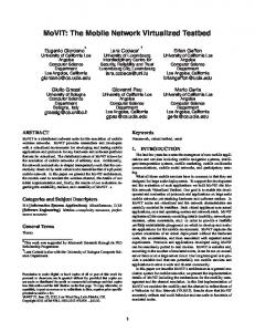
2 3 4 5 6 7 8 9 10 11 12 13 14 NODE NUMBERFig. 9. Effect of a node failure on maximum number of hops. 1
be observed when there is a link failure in these networks. The networks described in [12]-[14] also provide improvements in reliability and fault tolerance; however, the double-loop topologies described in this paper have easier and simpler routing under failures. The optimal FLBH network architecture provides good protection against node and link failures. As many alternate routes exist between any node pair, paths can be selected adaptively in case of failures. To study the effect of a singlenode failure or a single-link failure we consider a network of 15 nodes. For this size, in the optimal FLBH network, the skip distance is s = 3 and the diameter when there are no failures is d = 5. Since the network is symmetric every node will have a diametrically opposite node at a hop distance of 5. Whe'n a node or link fails some messages may not be able to use the shortest routes to reach their destinations. The effect of a node or link failure is therefore to increase the maximum number of hops for some nodes and increase the average number of hops slightly. Fig. 9 shows the effect of node #0 failure on optimal loop and daisy-chain loop, and Fig. 10 shows the effect of link 0
--
failure
on
optimal loop
-_____ OPTIMAL
I I I I i' I I I I I I I 2 3 4 S 6 7 8 9 10 11 12 13 14 NODE N6MBER Fig. 10. Effect of a link failure on maximum number of hops. I
vO
I
1
-
Now we compute the number of alternate routes between any two farthest nodes in the network. There is one path using only forward links, that may not be a shortest path. There are several additional paths that use backward links and forward links. All these routes are shortest routes between that node
pair. Each of these routes consists of b LN/(s + 1)] backward hops and (s - 1) forward hops. We get different routes depending on the relative positions of "long" steps and forward hops along the route. Therefore, the number of alternate routes between the two farthest nodes is the number of combinations of b out of (b + s - 1) objects; that is, =
NR
-
1
= (
b
+
(b
s
+
s
-
I)
The expression for the number of distinct routes R s
-
1
is given
by
)
For Liu's loop NR = 2; for daisy-chain NR = (bil) = 2 + LN/3i; for the optimal loop, with s =
1
+
and daisy-chain loop. A useful measure of fault tolerance is to compute the terminal pair reliabilities [4]. We consider two farthest nodes for + j+ terminal reliability analysis. In the optimal double-loop network there exist many alternate routes between any pair of nodes, and therefore we expect high terminal pair reliability. For the two farthest nodes, one can intuitively see that the For example, a 20-node network has s = 4, b = 4, and the following properties hold: number of distinct routes between any two farthest nodes is, + (7)- 36. terminal reliability number of alternate routes; and If we maximize NR with respect to s, we find that the value of s is FVNK1. However, for most values of N, optimum terminal reliability diameter' s = L/iNJ also gives the same maximum value for NR. Therefore, for most values of N, and for N the square of an We havealready shown that the diameter is minimized when integer, the optimal loop will also maximize the number of s LV?NJ. Also, for this value of s, the number of alternate distinct routes between any two farthest nodes. routes between the two farthest nodes will be higher in In Table III, we present the values of NR for the Optimal the optimal loop than in the daisy-chain loop, as shown in the FLBH for typical values of N. The value (NR - 1) represents the number of alternate following derivation. Therefore, we can conclude that the optimal loop network gives higher terminal pair reliability shortest routes between the two farthest nodes. Additionally, than the daisy-chain loop. there will be other routes of longer hop distances than the s
a
a
=
Authorized licensed use limited to: Univ of Calif Los Angeles. Downloaded on August 02,2010 at 17:35:11 UTC from IEEE Xplore. Restrictions apply.
54
IEEE TRANSACTIONS ON COMPUTERS, VOL.
TABLE III DIAMETER AND NUMBER OF ALTERNATE ROUTES
Optimal FLBH Diameter NR
N
10 20 30 40
4 7 9 10
j
7 36 127 253
C-34,
NO.
1,
JANUARY
1985
processor system. A separate host processor can perform the reconfiguration in case of failures. The reconfiguration of interconnections under failures, and addition of new nodes can be done easily if the interfaces are brought to one place. Interestingly, if all the links are bidirectional, the optimal double-loop interconnection is precisely the same as the Illiac IV structure [1]. REFERENCES
diameter of the network. From Table III it is clear that the number of alternate paths increases exponentially assuring a higher probability of communication between any node pairs. Certain types of double-node failures cause trapped nodes. This situation arises when both the outlink or inlink nodes of any node has failed. The trapped node can only receive from or send packets to other nodes, but cannot do both. This means the trapped node is also down for all practical purposes. Such a situation happens when two failed nodes are at a distance (\/Ni + 1). In an optimal double-loop network of N nodes, there are exactly N double-node failures that lead to this situation out of a possible N(N - 1)/2 combinations of two node failures. Therefore, the fraction of double-node failures resulting in a trapped node situation is FDN
=
2N N(N-
1)
2 (N- lY
Note that this fraction becomes increasingly small as N inFurthermore, when a single node is trapped, only a fraction 1/N of all possible network connections is disabled. In contrast, in a (nonoptimal) double-loop architecture all double failures cause a network partition in which on the average one half of all network connections are disabled. This implies that the probability of a connection being disrupted in an optimal double loop is O(N2) times smaller than the corresponding probability in a conventional double loop, which is a remarkable improvement.
creases.
VIII. CONCLUDING REMARKS This paper presented an optimal double-loop topology for locally distributed networks. This network is shown to provide the optimum performance with respect to maximum number of hops, average number of hops, throughput rate, and terminal reliability. In particular, better performance is achieved with respect to previously proposed topologies such as DDLCN and daisy-chain loop. The cost of this topology in length of loop cable is N(LVNKj + 1), as compared to 2N for DDLCN and 3N for daisy-chain. Nodal interface costs are the same for all these architectures. One should realize that in a local network cable cost represents only a small fraction of total system cost. Therefore, it appears that the additional cable cost is well compensated for by the performance benefits of the optimal loop topology. This type of interconnection scheme among host processors may find applications in a tightly coupled multi-
[1] G. H. Bames et al., "The Illiac IV computer," IEEE Trans. Comput., vol. C-17, pp. 746-757, Aug. 1968. [2] B. W. Arden and H. Lee, "Analysis of chordal ring," IEEE Trans. Comput., vol. C-30, pp. 291-295, Apr. 1981. [31 D. Farmer and E. Newhall, "An experimental distributed switching system to handle bursty computer traffic," in Proc. ACM Symp. Prob. Optimizations Data Commun., Oct. 1969, pp. 1-23. [4] A. Grnarov, L. Kleinrock, and M. Gerla, "A new algorithm for network reliability computation," in Proc. NBS Comput. Networking Symp., Gaithersberg, MD, Dec. 1979, pp. 17-20. , "A highly reliable distributed loop network architecture," in Proc. [5] Int. Symp. Fault-Tolerant Computing, Kyoto, Japan, Oct. 1980, pp. 319-324. [6] M. Imase and M. Itoh, "Design to minimize diameter on building-block network," IEEE Trans. Comput., vol. C-30, pp. 439-442, June 1981. [7] H. Jafari, T. G. Lewis, and J. D. Spragis, "Simulation of a class of ring-structured networks," IEEE Trans. Comput., vol. C-29, pp. 385-392, May 1980. [8] L. Kleinrock, Queueing Systems Vol. II: Computer Applications. New York: Wiley Interscience, 1976. [9] M. T. Liu, "Distributed loop computer networks," in Advances in Computers, Vol. 17. New York: Academic, 1978, pp. 163-221. [10] Y. Oh and M. T. Liu, "Interface design for distributed control loop networks," in Proc. 1977 Nat. Telecommun. Conf., Los Angeles, CA, Dec. 1977, pp. 31:4(l)-31:4(6). [11] J. Pierce, "Network for block switches of data," Bell Syst. Tech. J., vol. 51, no. 6, pp. 1133-1145, July/Aug. 1972. [12] D. K. Pradhan and S. M. Reddy, "A fault-tolerant communication architecture for distributed systems," in Proc. FTCS-J1, June 1981, pp. 214-220; see also, IEEE Trans. Comput., vol. C-31, pp. 863-870, Oct. 1982. [13] D. K. Pradhan, "Interconnection topologies for fault-tolerant parallel and distributed architectures," in Proc. 1981 Int. Conf. Parallel Processing, Aug. 1981, pp. 238-242. [14] , "On a class of fault-tolerant multiprocessor network architectures," in Proc. 3rd Int. Conf. Distrib. Comput. Syst., Oct. 1982, pp. 302-311. [15] C. S. Raghavendra and M. Gerla, "Optimal loop topologies for distributed systems," in Proc. 7th Data Commun. Symp., Mexico City, Mexico, Oct. 198 1, pp. 218-223. [16] C. S. Raghavendra, M. Gerla, and D. S. Parker, "Multi-connected loop topologies for local computer networks," in Proc. INFOCOM 82, Mar. 1982. [17] C. S. Raghavendra, "Fault tolerance in computer communication architectures," Univ. California, Los Angeles, CA, Dep. Comput. Sci., Tech. Rep. CSD-820928. [18] C. C. Reames and M. T. Liu, "A loop network for simultaneous transmission of variable-length messages," in Proc. 2nd Annu. Symp. Comput. Arch., Jan. 1975, pp. 7-12. [19] J. H. Saltzer and K. T. Pogran, "A star-shaped ring network with high maintainability," in Proc. Local Area Commun. Network Symp., Mitre Corp., May 1979, pp. 179-190. [20] J. H. Saltzer, D. D. Clark, and K. T. Pogran, "Why a ring?," in Proc. 7th Data Commun. Symp., Mexico City, Mexico, Oct. 1981, pp. 211-217. [21] R. S. Wilkov, "Construction of maximally reliable commu cation networks with minimum transmission delay," in Proc. 19706IEEE Conf. Commun., June 1970, vol. 6, pp. 4210-4215. [22] - , "Analysis and design of reliable computer networks," IEEE Trans. Commun., vol. COM-20, no. 3, pp. 670-678, June 1972. [23] J. Wolf, M. T. Liu, B. Weide, and D. Tsay, "Design of a distributed fault-tolerant loop network," in Proc. 9th Annu. Int. Symp. FaultTolerant Computing, Madison, WI, June 1979, pp. 17-24. [24] J. Wolf, B. Weide, and M. T. Liu, "Analysis and simulation of the distributed double loop computer networks," in.Proc. NBS Comput. Networking Symp., Gaithersberg, MD, Dec. 1979, pp. 82-89.
Authorized licensed use limited to: Univ of Calif Los Angeles. Downloaded on August 02,2010 at 17:35:11 UTC from IEEE Xplore. Restrictions apply.
55
RAGHAVENDRA et al.: RELIABLE LOOP TOPOLOGIES
. . . . .I
aI ¢. X
, I.,,
C. S. Raghavendra (S'80-M'82) was born in India
in March 1955. He received the B.Sc. (hons) degree in physics from Bangalore University, Bangalore, India, in 1973, the B.E. and M.E. degrees in elec