Computer Simulation of Annealing and Recovery Effects on Serrated Flow in Some Al-Mg Alloys. MICHAEL V. GLAZOV, DANIEL. J. LEGE, FREDERIC BARLAT, ...
Computer Simulation of Annealing and Recovery Effects on Serrated Flow in Some Al-Mg Alloys MICHAEL V. GLAZOV, DANIEL. J. LEGE, FREDERIC BARLAT, and OWEN RICHMOND Strain to the onset of serrated flow (εc) remains an important measure of formability for aluminum alloys, especially in the 5XXX-series (Al-Mg) alloys, since serrated flow can signal undesirable surface appearance as well as premature fracture. For this reason, extensive experimental and theoretical work has been performed in order to identify the key parameters that affect the onset of serrated flow. In particular, it has been determined that thermal treatments applied after cold rolling can favorably impact the εc of an Al-Mg alloy (5182 can end stock). Recent developments of dislocation density–related constitutive modeling provide a unique opportunity to theoretically address this important problem. Using the Ananthakrishna model described and extensively tested previously, results are presented here to show that recovery processes (as simulated by a reduction in the initial density of dislocations) can cause significant increases in εc, in agreement with the aforementioned experimental results. Smaller initial dislocation densities can result in a considerable delay of serrated behavior. Using standard computational tools used in nonlinear dynamics (phase portraits and bifurcation diagrams), the influence of recovery (as mimicked by initial dislocation density changes) has also been examined on Luders behavior, and results which confirm previous semiquantitative considerations in the literature have been obtained. The model in its present form is limited to homogeneous straining and, thus, cannot treat the propagative instabilities often observed in experiments. Therefore, the next step in the theoretical development will be to include effects of nonhomogeneous strain.
I.
INTRODUCTION
IN an effort to optimize formability and retain high strength in 5XXX-series (Al-Mg) aluminum alloys, a considerable amount of experimental work has been performed.[1,2] Formability was quantified using several parameters and experimental techniques: strain to the onset of serrated flow (εc), Olsen cup height, bulge test, guided bend test, and standard uniaxial tension tests.[1] Hollinshead showed, in his detailed study of formability of 5182 end stock, that Olsen cup heights, tensile, ultimate tensile strength-yield strength, strain to onset of serrated flow, and serrated-flow characteristics correlated to the amount of Mg in b'-precipitate form or in solid solution.[2] Several other experimental techniques were used to shed additional light on the formability of these materials (e.g., a technique based upon CODF (crystal orientation distribution function) measurements to predict anisotropic yield surfaces, forming-limit diagrams, acoustic emissions etc.). As a result of these experimental efforts, two microstructural factors were identified as affecting formability: precipitate and defect (dislocation) populations, both their interactions and their densities. It is an established fact that an increased amount of Mg in the form of Mg5Al3 (rather than in solid solution) correlates with formability.[1,2] However, in the course of the thermal exposure which is necessary to achieve an appreciable density of precipitates, the dislocation population decreases significantly as a result of MICHAEL V. GLAZOV, Senior Scientist, DANIEL J. LEGE, Manager, FREDERIC BARLAT, Technology Specialist, and OWEN RICHMOND, Director, are with the Alcoa Technical Center, Alcoa Center, PA 15069-0001. Manuscript submitted April 10, 1998. METALLURGICAL AND MATERIALS TRANSACTIONS A
recovery. This also is generally thought of as a favorable process for enhancing formability. However, because it is virtually impossible in a laboratory setting (not to mention in field tests and in plant practices) to separate these two metallurgical factors (increased density of precipitate and decreased dislocation density), decisive evidence in favor of either metallurgical factor was unavailable. Recent dramatic developments in nonlinear dynamics, in general, and in dislocation density–related constitutive modeling of metallic materials, in particular,[3,7] now provide a theoretical framework and computational tools for assessing the influence of these two metallurgical factors separately and independently.* The reason is that the inter*Of course, it is important to state clearly that, in its present form, the current article does not address the problem of differing populations of precipitates.
nal-variable models which can be used for this assessment can be fine-tuned to account for the precipitate population. At the same time, by changing only the initial values of the internal variables which are associated with the densities of different dislocation populations (mobile, immobile, and Cottrell-type dislocations with atmospheres), it becomes possible to simulate the effects of recovery alone. Thus, an opportunity arises to unambiguously distinguish between the two effects, which are inseparable in experimental work. An outline of the present article is given below. Since a detailed discussion of the modified Ananthakrishna model was given previously,[3,4,8] only a very brief description is given here in Section II, in order to provide a basis for understanding the results of computer simulation. At the same time, considerable attention is paid to the link between mesoscopic dislocation dynamics and the macroVOLUME 30A, FEBRUARY 1999—387
scopic load-displacement response of a sample via a so-called ‘‘machine’’ equation. The conditions under which this equation can be obtained are specifically demonstrated. In Section III, a brief description of an implicit integration algorithm used to obtain all of the results is given, and the potential pitfalls which should be avoided in computer modeling of systems with several different time scales are discussed. Section IV is mostly devoted to the comparison of numerical results to the existing experimental data for 5182 can end stock and also to the recent results by Mertens et al.[9] for a 5052 alloy. Analyses of the influence of initial dislocation densities, related to annealing and recovery, on the Portevin–Le Chatelier (PLC) behavior (serrated flow) and the Luders behavior (a single-plasticity tooth) are performed, and results which are consistent with both existing experimental data and data described in the literature are obtained. Some general results from nonlinear dynamics (stability and phase portraits), which shed additional light on the behavior of the model, are also discussed. Finally, some conclusions are drawn and recommendations for future work are outlined in Section V.
II.
BRIEF DESCRIPTION OF THE MODEL
A detailed discussion of the Ananthakrishna model can be found in his original works.[3,4] Modifications of the model necessary to account for cyclic loading were described in Reference 5, and most recent applications to understanding Luders-type instabilities were given in References 8. According to Reference 3 and 4, the Ananthakrishna model introduces three dislocation populations: g, glissile (mobile); s, sessile (immobile); and i, interactive with atmospheres of point defects. Dislocation kinetics are modeled by considering the following set of quasichemical reactions:
u vg
g
g1g g1g g1s s g i
l a a'
. g1g
km '/2
m
. 0
(b)
[1b] 0
[1c] [1d]
. g
[1e]
. i
[1f]
. s
[1g]
where u is a breeding constant, Vg is the average velocity of the glissile dislocations, and k, m', l, a, and a' are kinetic constants (reaction rates). These quasichemical processes are supposed to describe dislocation generation by the multiple cross-glide mechanism of Eq. [1a] (thus providing an opportunity to connect mesoscale dislocation dy-
388—VOLUME 30A, FEBRUARY 1999
(a)
[1a]
. s1s
(1 2 k ) m '/2 .
namics to the macroscopic stress-strain response of the material), conversion of two glissile dislocations into two sessile dislocations (Eq. [1b]), annihilation of dislocations (Eqs. [1c] and [1d]), and finally, mutual transformations between the three dislocation types (Eqs. [1e], [1f], and [1g]). In the Ananthakrishna model, these three populations lead to three dislocation evolution equations which are then
(c)
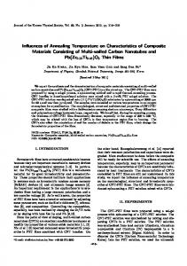
(d ) Fig. 1—(a) A traveling deformation front in aluminum alloy 5052. (b) through (d ) Transition from repeated yielding to continuous front motion for increased pulling speeds (from 2.54 to 25.4 to 254 mm/s, respectively).[9]
METALLURGICAL AND MATERIALS TRANSACTIONS A
coupled to a machine equation connecting the strain rate on a material element to the imposed velocity on the specimen-tensile machine system, giving the following final set of equations:[3,4] Nz g 5 u Vg(s *)Ng 2 µN 2g 2 aNg 1 lNs 2 m 'NgNs Nz s 5 kmNg2 2 m'NgNs 2 lNs 1 a'N'i Nz 5 aN 2 a'N i
g
[2]
i
sz a 5 K[εz 2 b0NgVg(s *)]
In the machine equation, the coefficient K stands for the generalized effective stiffness of the ‘‘sample 1 machine’’ system and εz is the imposed ‘‘strain rate’’ on the system.* *Generally speaking, a division of dislocations into those of mobile and immobile might be insufficient. It is difficult to imagine that no difference exists between screw and edge dislocations as far as the machine equation is concerned. Indeed, in fcc metals, e.g., aluminum, slip is mostly localized to close-packed planes {111} in the directions of ^110&, while, for bcc metals, the dominant feature is pencil glide–cross-slip of dislocations in the planes {110}, {112}, and {123}, all of which contain the same direction ^111&, and, also, nonplanar spreading of dislocation cores of the ^111& zone. Equally important, in the case of dissociation of dislocations in fcc materials into partials, e.g., Shockley partials with 1/6^112& Burgers vectors, the partials should be described somewhat differently than normal dislocations, because the corresponding closed circuit must start and finish in the surface of the stacking fault.
The second term within brackets is the plastic strain rate (εz p) of a material element which is proportional to the Burgers vector (b0), the number of glissile dislocations, and the velocity of gliding (Vg(s *)). As a first approximation, the velocity of gliding can be related to the effective stress on a material element by Vg 5 V0 (s * /s0)m
[3]
where s0 is the stress required to induce a velocity of V0 and m is an empirical constant (‘‘dislocation responsiveness’’). The effective stress s * in Eq. [3] can be related to the applied stress sa in the following simple way:[3,4]
s * 5 sa 2 h N 1/2
[4]
where h is a constant characteristic of hardening and N is the total dislocation density, i.e., N 5 Ng 1 Ns 1 Ni. Reducing these equations to dimensionless form by introducing proper scaling of variables results in the following:
mNg 5 l X; m Ns 5 u V0Y; ma 'Ni 5 la Z;
[5]
s 5 ws0 ; t 5 u V0 t where X, Y, Z, t, and w are new dimensionless variables. As a result of this substitution, the original system (Eq. [4]) can be rewritten as[4]
@
~
!#
ab z X 5 s 2 h bX 1 Y 1 Z c
1 2
m
[6a]
X 2 bX 2 2 a X 1 Y 2 XY z Y 5 b (kbX 2 2 XY 2 Y 1 a Z )
[6b]
z Z 5 c (X 2 Z )
[6c]
METALLURGICAL AND MATERIALS TRANSACTIONS A
sz 5
@
[6d]
~
!!(
~
1
ab d e 2 s 2 h bX 1 Y 1 Z c
2
m
#
X 1 g Z)
where e is the dimensionless total strain rate εz . Since the link between the mesoscopic dislocation kinetics and the macroscopic stress-strain response of a material is achieved via the machine equation, several important comments about its nature and limits of applicability are appropriate at this point. In order to perform this analysis, it is convenient to consider Eq. [6d] in its standard dimensional form, i.e., sz a 5 (K/d ) [εz 2 b0NgVg(s *)], where the generalized stiffness can be expressed as K5
kEd kd 1 ES
[7]
Here, d is the specimen length, S is its cross-sectional area, E is the Young’s modulus, and k is the spring constant of the machine. It has been demonstrated that K can even change the character of plastic instabilities observed in the system dramatically. This result is not surprising, because changing the generalized stiffness is related to changing the stress rate applied to the sample (Eq. [6d]), and this last parameter has been found to play a key role in the formation and propagation of plastic instabilities in Al alloys of the 5XXX series.* Examples include experimental and mod*It is also easy to understand, on the basis of our previous work,[8] the ‘‘size effects’’ in propagative plastic instabilities. It is an established fact that Luders phenomena are generally observed in thin wires, while PLC behavior is seen in larger samples. Using our previous results and a definition of the machine equation, one can immediately see that smaller values of machine stiffness (i.e., thick specimens!) generally enhance the PLC-like instabilities, while thin specimens will enhance Luders-like behavior, a result important for practical applications.
eling work by Lalli for an Al-4.6 pct Mg alloy (FRZ-029)[10] and also recent experimental work by Mertens et al. on a 5052 Al alloy.[9] These workers have established that a continuous transition from a single plastic front to hopping motion was observed when the applied strain rate changed in the interval from 254 to 2.54 mm/s (Figure 1).[9] In his extensive and detailed experimental work on formability fundamentals/variability in ec measurements (tension tests of 5182 end stock), Brem has also established that testing speed, specimen design, and the type of testing machine (i.e., with stiffer and softer frames) all significantly affected the εc results, the pulling speed being the most important factor.[11] In the form of Eqs. [6a] through [6d], the model can be described as an ‘‘internal-variables constitutive model’’ of serrated flow in metallic materials.[12] The next important limitation associated with the machine equation in the form of Eq. [6d] is that it describes homogeneous yielding within the whole volume of the sample. On the other hand, numerous experimental data (e.g., Reference 9), indicate that in many cases, although not necessarily always, serrated yielding on stress-strain curves is accompanied by propagative plastic instabilities—Luders bands and PLC bands. Thus, a more appropriate form of the machine equation would be
VOLUME 30A, FEBRUARY 1999—389
(a)
(b)
(c)
(d)
Fig. 2—Induced, nonexistent Portevin–Le Chatelier effect obtained with the explicit integration algorithm (Runge–Kutta of the fourth order). The values of the integration time step were (a) 0.5, (b) 0.43, and (c) 0.35, respectively. (d ) Correct results without artificial ‘‘temporal instabilities’’ obtained using Rosenbrock’s implicit integration algorithm described in the article. One can also get the correct result with the explicit Runge–Kutta method, but the time-step value, 0.03, is prohibitively small to avoid instabilities. The values of the parameters of the model were as follows: a 5 0.2, b 5 0.002, c 5 0.008, d 5 0.001, e 5 120, h 5 0.2, k 5 0.8, and m 5 80. d
sz a 5 (K/d ) [«z 2 (1/d )
*
«z p d x]
[8]
0
which makes the whole model nonlocal and accounts for a possible nonuniform distribution of plastic strain rate throughout the length of the sample. Spatially coupled models of plastic instabilities will be discussed in more detail in a future work. III.
NUMERICAL INTEGRATION ALGORITHM AND SEVERAL POTENTIAL PITFALLS
There is one more property of the model under consideration that requires some attention. Because of the multiscale behavior (rapid oscillations superimposed on 390—VOLUME 30A, FEBRUARY 1999
relatively ‘‘smooth’’ hardening behavior), it is difficult to integrate the system of Eqs. [6a] through [6d] using conventional explicit algorithms. The extremely small time step necessary in those parts of the solution with temporal instabilities makes the integration over multiple periods prohibitively slow. In addition to that, and because explicit integration algorithms (e.g., Runge–Kutta of any order, forward Euler, etc.) are not unconditionally stable,[14] nonexistent ‘‘PLC oscillations,’’ which appear surprisingly realistic, can be easily obtained (the same problems arise in finite-element calculations of plastic instabilities). Examples of such ‘‘temporal dissipative structures’’ are presented in Figures 2(a), (b), and (c) for the Ananthakrishna model. In all of the cases, the frequency and amplitude of ‘‘serrations’’ are determined by the value of the integration time step rather than by a material instability itself. Figure METALLURGICAL AND MATERIALS TRANSACTIONS A
(a)
(a)
(b)
(b)
Fig. 3—Different values of εc (strain to the onset of serrated flow) corresponding to (a) initial dislocation density 107 m22 and (b) initial dislocation density 1010 m22. It is obvious that for a well-annealed sample, case (a), transition to serrated flow was delayed. The values of model parameters in both cases were a 5 0.7, b 5 0.002, c 5 0.008, d 5 0.0001, e 5 120, h 5 0.2, k 5 0.9, and m 5 2.
Fig. 4—The behavior of mobile dislocation density for two cases: (a) initial dislocation density 107 m22 (well-annealed sample) and (b) initial dislocation density 1010 m22. In the first case, the transition to serrated flow takes place later in time (i.e., for proportional loading, at higher values of strain εc). All parameters are as in Fig. 3.
Σ a k) 1 hf ' z Σ g k , i21
2(d) represents the results which correspond to a sufficiently small time step for an explicit Runge–Kutta integration algorithm of the fourth order. Obviously, such PLC-like ‘‘instabilities’’ are unacceptable and must be avoided. To overcome this problem, the fourth-order Rosenbrock algorithm, with an automatically adjustable time step, was used in all simulations. Its brief description is given subsequently.[15] It integrates a system of ordinary differential equations in the form of
Σ ck s
y (x0 1 h ) 5 y0 1
i51
i i
[9]
where the corrections ki can be found by solving a system of ‘‘s’’ linear equations that look as follows:[15] METALLURGICAL AND MATERIALS TRANSACTIONS A
(1 2 g h f ' ) z ki 5 h f (y0 1
j51 i21
j51
ij
ij j
j
i 5 1, . . . , s
[10]
In the system of Eq. [10], the Jacobian matrix is denoted as f ', and the coefficients g, Ci, aij, and gij are fixed constants of this integration technique which do not depend on a specific problem. Equation [10] can be solved successively for k1, k2, and so on. The effectiveness of all stiff integration techniques depends heavily on how the procedure of automatic step-size adjustment is implemented. The algorithm given in Reference 15 did not work well for temporal dissipative structures in fatigued (or monotonically tested) metallic alloys, because in the smooth regions of solutions the step size VOLUME 30A, FEBRUARY 1999—391
rapidly became so large that the algorithm was not able to trace the fine structure of solutions in the areas of instabilities. As a result of a time-consuming numerical experimentation, it was found that imposing an (adjustable) upper bound on the value of the step helped effectively control the behavior of the algorithm. IV. THE RESULTS OF COMPUTER MODELING, THEIR DISCUSSION, AND COMPARISON TO EXISTING EXPERIMENTAL DATA Figures 3(a) and (b) represent the results of computer experiments simulating the PLC effect for two different initial dislocation densities, 107 and 1010 m22, respectively. In both cases, the initial densities of all three populations of dislocations were assumed to be equal to each other.* Fig*The initial density of mobile dislocations in the second case was 108 m22. We have found that a further increase of the initial density of mobile dislocations resulted in nonphysical effects in the beginning of the stressstrain curve (induced instability of the algorithm).
(a)
ures 4(a) and (b) give the same information in terms of the change in the behavior of the mobile dislocation density. It can be clearly seen from both sets of figures that the decrease in the overall initial dislocation density results in a considerable delay of serrated yielding, in qualitative agreement with the experimental data of Lege.[1] However, comparison of Figures 3(a) and (b) (and also of Figures 4(a) and (b)) indicates that, although there is a considerable delay in the onset of serrated-flow behavior, the constitutive nature of the instability remains intact. This observation can be further substantiated if the so-called ‘‘phase portraits’’ corresponding to these two initial dislocation densities are constructed. Phase portraits provide valuable information on the oscillatory behavior, because they are constructed in a different space: ‘‘mobile dislocation density vs immobile dislocation density,’’* rather than ‘‘dislocation density vs *Or ‘‘Cottrell-type dislocation density vs immobile dislocation density,’’ for example.
time.’’ As a result, information about the phase of the signal is lost. However, identical constitutive behaviors of oscillatory systems manifest themselves in coinciding phase portraits if these behaviors (amplitudes of oscillations and their frequencies) remain the same. Figure 5 clearly demonstrates that phase portraits remain identical in both cases, although the initial states (i.e., figurative points in the phase space) are, of course, different. This result (i.e., independence of constitutive behavior from initial dislocation densities in these computer experiments) should be interpreted in a broader context of modern theory of dynamic systems. Is it possible, by changing the initial conditions of a differential Cauchy problem, to change the nature of dynamic behavior qualitatively? The answer to this question is affirmative, and the explanation is given next. Usually, the standard procedure called ‘‘linear stability analysis’’ is performed in order to determine the area in parameter space which corresponds to the emergence of oscillations.[3,4] For that goal, the stability of the thermodynamic (i.e., steady-state) branch of solutions is probed for derivatives of X, Y, Z, and w, with respect to time, that are equal to zero. For a linearized equation, Pa 5 (Xa, Ya, 392—VOLUME 30A, FEBRUARY 1999
(b) Fig. 5—Phase portraits (projections onto Ns 2 Ni plane). Ns is the density of immobile dislocations, and Ni is the density of dislocations with atmospheres of point defects corresponding to different initial dislocation densities: (a) initial dislocation density 103 cm22 and (b) initial dislocation density 1010 m22. It is clear that although the initial trajectories in the phase space are different, they soon form the same closed contour called ‘‘the limit cycle’’ (bold lines). This is direct evidence that the constitutive behavior of the model did not change (in both cases, oscillations of the same amplitude and frequency are observed), but the onset of jerky flow was delayed in the case of the well-annealed sample. Parameters are as in Figs. 3 and 4.
Za, and wa), the region in the parameter space (a, b, c, d, e, g, h, and k) is sought in which the eigenvalues (vi) of this linearized form around Pa are complex with Re vi . 0. This ensures that the trajectories in the phase space (X, Y, Z, and w) will spiral out.[3,4] After this goal is achieved, a surface (S) surrounding Pa is sought, into which all such trajectories enter; this ensures a bounded variation of trajectories in the phase space, which often leads to a limit cycle, and consequently, to stable sustained oscillations of dislocation densities and stress with time (or strain, for proMETALLURGICAL AND MATERIALS TRANSACTIONS A
Fig. 6—A typical stress-strain curve for alloy 5182 can stock displaying the Portevin–Le Chatelier stress serrations (refer to explanations in the text).
portional loading). Finally, it is necessary to determine if changes in the initial conditions may result in different basins of attraction for figurative points in the parameter space. Most of this work must be performed computationally, and it has been done using the package of FORTRAN 77 programs which implement the fourth-order Rosenbrock implicit integration algorithm described previously. It is quite clear that a trivial solution (with respect to dislocation densities) exists such that X 5 Y 5 Z 5 0. However, for these values of dislocation densities, stress grows linearly with strain, and the behavior of the model, as expected, becomes purely elastic. Consequently, it might be expected that, for certain critical values of dislocation densities, a transition to plastic behavior will be accompanied by serrated flow, and if the initial densities of dislocations are lower than that critical value, serrated flow cannot be observed. Corresponding computer experiments have been METALLURGICAL AND MATERIALS TRANSACTIONS A
performed in order to determine these critical values, and they have been found to be negligibly small: Xc ,, 104 m22; Yc and Zc being of the same order of magnitude. Since it is virtually impossible to obtain these dislocation densities by using experiments or plant practices, the conclusion that should be made on the basis of these computer experiments is that annealing and recovery can significantly delay the onset of undesired PLC-like plastic behaviors, but they cannot eliminate serrated flow altogether. An example of a uniaxial tensile test for alloy 5182 is illustrated by Figure 6, and εc can be unambiguously determined in this test. Generally, materials with higher εc values distribute strain more uniformly and result in greater formability, and εc typically increases with thermal treatment time and temperature, while the density of dislocations decreases.[1] In order to examine the effects of both initial dislocation density and applied strain rate, computer VOLUME 30A, FEBRUARY 1999—393
(a)
(b)
(c)
(d)
Fig. 7—Influence of applied strain rate on serrated flow. Initial dislocation density was equal to 107 m22 in all cases. (a) Strain rate εz 5 6.7z1025 s21, (b) εz 5 8z1025 s21, (c) εz 5 1024 s21, and (d ) εz 5 1.2z1024 s21. All other parameters are as in Fig. 3.
simulations were performed using the Ananthakrishna model described previously. In Figure 7, evidence is presented showing that, for well-annealed samples with an initial dislocation density of 107 m22, application of increased strain rate(s) results in a considerable delay of serrated-flow behavior. At a larger initial dislocation density (Figure 8), a continuous transition was obtained from the PLC-like instability to the Luders phenomenon (‘‘plasticity tooth’’) with increasing strain rate. This is in excellent agreement with experimental results by Mertens et al.[9] It is important to emphasize that these results do not contradict the phenomenological classification of plastic instabilities into strain-softening and strain-rate softening mechanisms, as proposed by Estrin and Kubin[17,18,19] and further elaborated upon by Zaiser and Hahner,[20,21] but rather indicate that the conditions of testing (i.e., soft machine vs rigid machine) could play an important role in observed plastic behaviors.
394—VOLUME 30A, FEBRUARY 1999
Finally, since the modified Ananthakrishna model provides a unique opportunity to describe Luders-type instabilities (although it was originally formulated for strain-rate softening phenomena), it was only natural to explore how the Luders-like instability would be affected by changes in the initial dislocation densities. Johnston and Gilman performed simple calculations illustrating the effect of changing the initial density of mobile dislocations on the upper yield point of stress-strain curves.[6] The initial dislocation density in their calculations varied from zero (which obviously corresponded to purely elastic behavior) to 5z1010 m22 (Figure 9(a)).[6] As can be clearly seen from this figure, the upper yield point decreases with increasing dislocation density. The physical interpretation of this phenomenon is simple.[6] When the initial density of dislocations is low, dislocations cannot move fast enough at a constant value of applied strain rate to produce sufficient strain in the spec-
METALLURGICAL AND MATERIALS TRANSACTIONS A
(a)
(b)
(c)
(d)
Fig. 8—Influence of applied strain rate on serrated flow. Initial dislocation density was higher than in Fig. 7 (10 m22). (a) Strain rate εz 5 6.7z1025 s21, (b) εz 5 8z1025 s21, (c) εz 5 1024 s21, and (d ) εz 5 1.33z1024 s21. All other parameters are as in Fig. 7. 10
imen. As the strain consequently rises, the dislocations start moving much faster, in complete agreement with Eq. [3]. This process comes to an instantaneous halt when the hardening rate becomes equal to zero (which corresponds to the time when the strain rate in the specimen equals the external strain rate). However, multiplication of dislocations must continue because the strain continuously increases (being an independent variable). The stress, therefore, must drop until the average velocity of gliding dislocations becomes slow enough for the two strain rates to match again.[6] As can be seen from Figures 9(b) through (e), results obtained using a more sophisticated approach completely confirm these simple qualitative considerations, i.e., there is a progressive decrease in the value of upper yield stress with increasing initial dislocation density.
METALLURGICAL AND MATERIALS TRANSACTIONS A
V.
CONCLUSIONS AND RECOMMENDATIONS FOR FUTURE WORK
1. As a result of direct computer experiments using the Ananthakrishna constitutive model, it has been demonstrated that a reduction in initial dislocation density related to the effects of annealing and recovery causes an increase in the strain before the onset of serrated flow. This agrees with the experimental results obtained by Lege[1] on some aluminum alloys, particularly 5182 can end stock. These results should be considered as an assumption which does not contradict the existing experimental information, but needs further verification with more detailed models of serrated flow. 2. The model also shows that, in well-annealed samples, the application of sufficiently high strain rates can con-
VOLUME 30A, FEBRUARY 1999—395
(a)
(b)
(c)
(d)
(e)
Fig. 9—Effect of initial dislocation density on yield point. (a) The results of Johnston.[22] (b) through (e) The results of our computer modeling for initial dislocation densities of 106, 107, 108, and 109 m22, respectively. The values of parameters are as follows: a 5 0.2, b 5 0.002, c 5 0.008, d 5 0.001, e 5 120, h 5 0.2, k 5 0.8, and m 5 2.
396—VOLUME 30A, FEBRUARY 1999
METALLURGICAL AND MATERIALS TRANSACTIONS A
siderably delay and, in principle, suppress the onset of instabilities. Results from computer experiments conducted to determine the effects of initial dislocation density on Luders-type instabilities confirmed previously known experimental and theoretical results.[6] 3. The next step in modeling plastic instabilities in Al alloys must be related to making a transition to spatially coupled models, which account for propagative Luders and Portevin–Le Chatelier instabilities. Such modeling work should be performed in parallel with finite-element simulations and supported by experimental efforts aimed at capturing the most important features of such instabilities—their velocity, geometry, and influence on hardening behavior. ACKNOWLEDGMENTS The authors express their sincere gratitude to Mr. John Brem and Dr. Richard C. Becker, Alcoa Technical Center, for valuable discussions and help in interpreting the results of computer experiments. We are also grateful to Dr. Michael V. Braginsky (Department of Mechanical Engineering, The University of Pennsylvania) and to Professor Yuri Estrin (Head, Department of Mechanical Engineering, the University of Western Australia) for constructive criticism and several important suggestions that resulted in the improvement of the manuscript. REFERENCES 1. D.J. Lege: ALCOA Technical Center, Pittsburgh, PA, private communication, 1998.
METALLURGICAL AND MATERIALS TRANSACTIONS A
2. P.A. Hollinshead: ‘‘The Formability of 5182 End Stock: Influence of Partitioning of Mg Between b' and Solid Solution,’’ ATC Report, ALCOA Center, PA, 1995. 3. G. Ananthakrishna: Scripta Metall. Mater., 1993, vol. 29, pp. 118388. 4. G. Ananthakrishna and M.C. Valsakumar: J. Phys. D: Appl. Phys., 1982, vol. 15, p. L171. 5. M.V. Glazov, D.R. Williams, and C. Laird: Applied Physics A, 1997, vol. 64, pp. 373-81. 6. D. Hull and D.J. Bacon: Introduction to Dislocations, Pergamon Press, Oxford, United Kingdom, 1989. 7. Y. Estrin and L. Kubin: in Continuum Models for Materials with Microstructure, H.-B. Muhlhaus, ed., Wiley Interscience, New York, NY, 1995, pp. 395-450. 8. M. Zaiser, M.V. Glazov, L.A. Lalli, and O. Richmond: Comp. Mat. Sci., 1998, in press. 9. F. Mertens, S.V. Franklin, and M. Marder: Phys. Rev. Lett., 1997, vol. 78, p. 4502. 10. L. Lalli: ‘‘A Single Internal Variable Constitutive Model for an Al4.6% Mg Alloy (FRZ-029),’’ ATC Internal Report, ALCOA Center, PA, May 13, 1987. 11. J.C. Brem: ‘‘RCS Fundamentals/Variability in εc Measurements— 01B031,’’ ATC Internal Report, ALCOA Center, PA, Dec 4, 1984. 12. O. Richmond: J. Met., 1986, vol. 4, pp. 16-18. 13. J. Rice: J. Mech. Phys. Solids, 1971, vol. 19, pp. 433-55. 14. J.D. Hoffman: Numerical Methods for Engineers and Scientists, McGraw-Hill, New York, NY, 1992. 15. W.H. Press, S.A. Teukolsky, V.T. Vetterling, and B.P. Flannery: Numerical Recipes in FORTRAN. The Art of Scientific Computing, 2nd ed., Cambridge University Press, New York, NY, 1992. 16. Y.B. Zel’dovich: The Mathematical Theory of Combustion and Explosions. translated from Russian by D.H. McNeill, Consultants Bureau, New York, NY, 1985. 17. Y. Estrin and L.P. Kubin: Acta Metall., 1986, vol. 34, p. 2455. 18. Y. Estrin and L.P. Kubin: Res. Mechanica, 1988, vol. 23, p. 197. 19. Y. Estrin and L.P. Kubin: Mater. Sci. Eng. A, 1991, vol. 137, p. 125. 20. M. Zaiser and P. Hahner: Phys. Status Solidi A, 1997, vol. 199, p. 267. 21. M. Zaiser and P. Hahner: Mater. Sci. Eng. A, 1997, vol. 238, p. 399. 22. W.G. Johnston: J. Appl. Phys., vol. 33, p. 2716, 1962.
VOLUME 30A, FEBRUARY 1999—397