To be published as “Dimyadi, J., Clifton, C., Spearpoint, M., and Amor, R. Computerising Regulatory Knowledge for Building Engineering Design. Journal of Computing in Civil Engineering. doi: 10.1061/(ASCE)CP.1943-5487.0000572”
Computerising Regulatory Knowledge for Building Engineering Design Johannes Dimyadi1, Charles Clifton2, Michael Spearpoint3, Robert Amor4
Abstract Two common challenges in the computer-aided compliance audit of building engineering designs are being addressed in the current research. The first is to ensure that any form of computable representation is practical and relatively easy to use and maintain. The second is to ensure that performance-based regulatory compliance criteria, which are often qualitative in nature, are adequately addressed and correctly represented. This research proposes a method of automating manual compliant design procedures using an open standard executable workflow representation that can be specified and maintained relatively easily by a design engineer. This executable workflow is referred to as the Compliant Design Procedure (CDP) and can be described graphically using a subset of the open standard Business Process Model and Notation (BPMN). When executed in a computing environment, a CDP can guide the compliance audit process by checking a given design represented in a model view or subset of the BIM model, referred to as the Building Compliance Model (BCM), against the criteria in a digital building code, referred to as the Regulatory Knowledge Model (RKM), which is developed specifically for this purpose. This paper describes the process of modelling and encoding BCM, CDP and RKM, which are independent input components of the proposed compliance audit system framework. Supplementary human input and the ability to exchange input and output data with external simulation tools to solve some of the more complex qualitative criteria are important features of the framework. CE Database subject headings: Information management; automation; computer applications; decision support system; BIM; building information modelling Author keywords: Regulatory knowledge model; compliant design procedures; building compliance model; automated compliance audit; building code
BACKGROUND The emergence of building information modelling (BIM) at the start of the millennium has gradually replaced the function of computer-aided design (CAD) in documenting building designs in paper-based forms with the more collaborative approach of sharing building design information with various project stakeholders in computer processable forms. At the same time, computable representations of the regulatory knowledge have also gained much focus in research projects. Every aspect of a building design is bound by compliance with statutory requirements one way or another. Therefore, it is appropriate to consider a building design process 1
Department of Computer Science, University of Auckland, New Zealand, Private Bag 92019, Auckland 1142, New Zealand. Email:
[email protected] 2 Department of Civil & Environmental Engineering, University of Auckland, New Zealand. Email:
[email protected] 3 Department of Civil & Natural Resources Engineering, University of Canterbury, New Zealand. Email:
[email protected] 4 Department of Computer Science, University of Auckland, New Zealand. Email:
[email protected]
as the compliant process. There is certainly a need for computers to be able to process regulatory information for a compliance audit. However, the compliant design process is currently still largely a manual undertaking, which is known to be error-prone, inefficient, and often leads to duplication of effort as well as costly remedial work. One obvious reason is that there has not yet been a practical solution to automatically process regulatory information, which are typically written in natural language. Another reason is that many building standards present requirements that need complex designer judgement to implement which makes computer processing difficult. This paper describes a framework for automating manual compliant building engineering design procedures in conjunction with formalised regulatory knowledge in open standard representations. For illustration purposes, the Verification Method prescribed by the Building Code of New Zealand (NZBC) for the performance-based fire engineering design of buildings has been used in this project. This paper is an extension of the work presented at the joint ICCCBE and CIB W78 Conference in Orlando, Florida, USA, in July 2014 (Dimyadi et al., 2014).
COMPUTER-AIDED COMPLIANCE AUDIT SYSTEM The main objective of this research is to develop a computable representation of a performance-based building code and a practical method of using a computer system to automatically audit a building model for compliance with a set of performance-based criteria. The computer-aided compliance audit system developed in this research (ARCABIM) is based on a framework that can be described using the following system architecture (Figure 1).
Figure 1: System Architecture of ARCABIM ARCABIM consists of the core audit engine that can execute a set of Compliant Design Procedures (CDP) to check a given design represented in a Building Compliance Model (BCM), which is a model view or subset of the ISO standard BIM model, for conformance with constraints and rules defined in a Regulatory Knowledge Model (RKM) representing a particular regulatory document. The main input components to the system, i.e. BCM, CDP, and RKM, are described in more detail in subsequent sections of this paper. Depending on the type and status of the BIM model being shared, there may be information such as space usage classifications or material properties that are either not yet available or missing from the model. The framework has allowed this to be supplemented by human input and incorporated into a BCM, or to be provided by the user during the audit process. Additionally, the framework incorporates a facility for addressing qualitative performance-based criteria by allowing external simulations or calculation tools to be used to help with the analysis required for 2
evaluating such criteria. This feature is triggered by either a requirement in the RKM or specifically instructed by an activity in a CDP. The ARCABIM auditing process typically involves navigating through each task of the CDP, getting information from the BCM or RKM, and checking or evaluating any constraint or rules in the RKM. The process may stop at a task and request additional human input or generate input data for an external simulation or calculation tool to compute before continuing. The output of the system is a report documenting the audit process including a summary of the CDP tasks and a list of compliance issues, if any.
Building Information Modelling (BIM) BIM is an object-based collaborative approach to design, construct and manage a building. It can be used to maintain physical and functional information of a building for its entire life cycle. Computer applications within the Architectural, Engineering, and Construction (AEC) domain can now share BIM data using an open standard (ISO 16739) industry-specific data model known as the Industry Foundation Classes (IFC). Many open standard software toolkits are available for manipulating IFC data, which are needed for the purposes of a compliance audit. Being collaborative in nature, it is possible to supply additional layers of information to the base BIM model for specific applications. Similarly, not all information contained in the base BIM model is useful for a particular application so that they can be excluded. The ISO standard of specifying what type of information should be made available when sharing a BIM model is known as the Information Delivery Manual (IDM) (ISO 29481-1, 2010). The end product of IDM is the Model View Definition (MVD), which is a subset of the BIM model for a specific process or application (Hietanen, 2006).
Building Compliance Model (BCM) Using the MVD approach, a subset of the BIM model for compliant fire engineering designs has been developed in XSD (XML Schema Definition) as part of this research. This is referred to as Building Compliance Model (BCM) for the purposes of this research, shown in a high-level schema diagram in Figure 2. At the very minimum, a BCM must contain at least one building storey object (IfcBuildingStorey), at least one space object (IfcSpace) on each building storey, and one door object (IfcDoor) associated with each space object. In the schema diagram, solid rectangular boxes represent mandatory elements, dotted boxes represent optional elements, and the plus sign denotes the presence of further sub-elements. The schema specification can be used to develop a data serializer in conjunction with an open standard BIM information exchange systems such as the BIMserver (Beetz and van Berlo, 2010), which can then generate the required BCM for a given IFC-based BIM model.
3
Figure 2: BCM top level schema for compliant fire engineering designs
Approaches to Regulatory Knowledge Representation There have been numerous approaches taken by researchers over the last few decades to represent regulatory knowledge in a computable form. The most common approach to date has been rule-based systems (Eastman et al., 2009), which ranges from hard-coded decision tables (Fenves et al., 1969) to the use of language-based semantic inference systems (Pauwels et al., 2011). Other approaches include the use of hypertext and hypermedia (Evt et al., 1992; Feijó et al., 1994) as well as document markup techniques to assist with information access and knowledge extraction from regulatory documents (Hjelseth and Nisbet, 2011). There has also been research on the application of artificial intelligence and deontic modelling techniques to allow computers to interpret legal texts (Salama and El-Gohary, 2011; Zhang and El-Gohary, 2012). Although there have been some promising research outputs in this field, they are still far from being complete for implementation into a practical compliance audit system. Among these approaches, there is a common inclination towards embedding regulatory rules as part of the compliance audit system (Clayton, 2013; Ding et al., 2006), which may be easier to implement, but makes the system non-transparent as well as inflexible and costly to maintain in response to on-going regulatory amendments. For major development projects such as SMARTCodes in the USA (International Code Council, 2007), ePlanCheck in Singapore (Khemlani, 2005), and more recently AutoCodes in the USA (Wible et al., 2011), there may be a commercial justification for embedding rule-sets into the system, particularly when business collaboration of multiple stakeholders and proprietary systems and components are involved. However, the need to keep the regulatory knowledge representation independent of the compliance audit system has been identified as a key factor for a successful implementation (Greenwood et al., 2010). Other benefits of having a system independent regulatory knowledge representation include improved maintainability and data exchange portability with other systems. More importantly, however, rule-based systems on their own cannot adequately represent qualitative performance-based requirements that often rely on simulation and computational analysis for assessment. Furthermore, rule-based systems are not suitable for representing implicit regulatory knowledge and tacit compliant design knowledge that are only comprehensible to human designers.
Automating Compliant Design Procedures (CDP) There are two types of knowledge inherent in regulatory texts explored in the current research, namely compliant design paths, and the associated regulatory data comprising prescribed design parameters, constraints and rules. The choice of design scenarios and associated parameters represents a specific compliant design through a particular compliance path. Typically, multiple compliance paths exist in a given set of regulatory documents used for a compliant design. A compliant design path is inherent in a set of procedures followed by 4
the design engineer, often intuitively (Dimyadi and Amor, 2013). Formalising these design procedures explicitly into a set of computer executable workflows representing specific CDPs is considered more practical than trying to automatically extract multiple compliance paths directly from regulatory texts based on a given design specification. A method of automating manual CDPs has been developed in this research using an open standard computable model that can be used to guide the compliance audit process. CDP modelling with practical examples is discussed in more detail later in this paper. Having an independent open standard library of formalised CDPs gives design engineers or the building consent authority, depending on the use case, the ability to reuse them with consistent results across multiple projects. More importantly, it gives designers the responsiblity and ability to maintain them to suit their own practices and requirements. Formalising manual CDPs is essentially removing multiple compliant design paths inherent in regulatory documents and leaving the responsibility of specifying the desired path to follow based on preferred design options with human designers, where it should be. Machines are simply given the task of doing what they do best, which is to execute repetitive instructions and procedures consistently and accurately. For standardisation and quality control, a library of CDPs could be developed by an institution of professional engineers and published as a guideline of industry's best practice. The remaining compliant design parameters, prescribed constraints and rules that make up the other type of regulatory knowledge can be formalised and encoded into a Regulatory Knowledge Model (RKM), which is a computerised version of a specific building code or regulations. A method of encoding RKM, developed as part of this research, is discussed in more detail later in this paper.
NEW ZEALAND PERFORMANCE-BASED BUILDING CODE The New Zealand Building Code (NZBC) (New Zealand Parliament, 1992) is part of the Building Regulations of New Zealand, which is a subsidiary legislation made under the Building Act 2004. It is a performance-based building code containing 37 technical clauses that cover all aspects of building work including fire safety and protection, stability and durability of structure, accessibility, weather tightness, and energy efficiency. A performance-based code does not prescribe how a design and construction process should be carried out, but specifies functional requirements, and the qualitative or quantitative performance criteria to which the completed building and its components must meet throughout its intended life. This allows for innovation and uniqueness in designs proven by established scientific and engineering principles. Performance-based codes are usually accompanied by a set of prescriptive requirements, which are deemed to satisfy the performance criteria, to facilitate the compliance of common building designs. There are two means of compliance with the NZBC, which are deemed-to-satisfy methods published by the Ministry of Business, Innovation and Employment (MBIE), and alternative solutions. The deemed-to-satisfy methods are divided into “Acceptable Solutions” (AS), which must demonstrate full compliance with a set of prescriptive requirements, and “Verification Methods” (VM), which must demonstrate compliance by means of verification with a set of prescribed computational or design methods. Beyond AS and VM, there is an “Alternative Solution”, which is a specific design approach using a proven and peer-reviewed engineering design process that may include comparative analyses, numerical computations, simulations, laboratory tests, certifications, appraisals, and expert evidence.
Verification Method C/VM2 The Verification Method for fire safety compliant design is provided in the C/VM2 document, which is a framework for fire safety design (Ministry of Business, Innovation and Employment, 2013). Although prescriptive in principle, the C/VM2 document incorporates industry standard design methods that allow the use of external computation and/or simulation tools to help evaluate ten different fire design scenarios prescribed in 5
the document. The evaluation may include the determination of fire load and fire location, an assessment on the tenability condition of escape routes and structural stability, as appropriate. For example, the “Unknown Threat” (UT) fire design scenario is where a fire starts in a normally unoccupied space and can potentially endanger a large number of occupants in another space. The C/VM2 document consists of four parts that are arranged into numbered paragraphs. Part 1 contains a list of vocabulary and definitions and states the objectives and performance criteria. Parts 2 and 3 provide common rules and parameters for the analysis of design scenarios and movement of people. The rules and parameters are mainly provided in the form of tabulated data and mathematical equations, which are embedded in the text together with various constraints and conditions. Part 4 contains ten different sections, numbered 4.1 to 4.10, where each describes a particular design scenario and specifies the method of compliance as well as the required outcome for that scenario.
ENCODING REGULATORY KNOWLEDGE This section of the paper describes a practical method of encoding the compliance path inherent in CDPs using an open standard workflow model that can be used as an independent input component to the compliance audit system. This section also describes a method of encoding specific regulatory data, constraints and rules prescribed by a regulatory document using an open standard representation that is also independent of the compliance audit system, and which may be published as the equivalent computerised version of the regulatory document.
Modelling Compliant Design Procedure (CDP) It is becoming a standard practice for fire engineers in New Zealand to document the design procedure they use to evaluate each of the fire scenarios specified by the C/VM2 using a flow diagram. This practice is being requested by some of the principal building consent authorities in the country and is likely to become more widespread. These basic flow diagrams are intended to describe and document the compliant design path followed by the designer, which are essentially manual CDPs adopted for each design. To allow computer processing, CDPs can be described more formally using a general purpose open standard graphical language such as the Business Process Model and Notation (BPMN) version 2.0 (Object Management Group, 2011) and formalised into executable workflows. Using an open standard workflow language to represent CDP gives the user access to standard editing and visualisation tools, which facilitates modelling and maintainability. Another benefit of using an open standard is to allow data interoperability between computer systems. In the case of BPMN 2.0, workflow information can be shared using its underlying XML data exchange protocol, which is a commonly used general purpose open standard data exchange format. CDP is mostly a single user process for a specific task. For compliant fire safety designs, this can be represented adequately in a single process environment using a subset of BPMN 2.0 components (Table 1). There are essentially four groups of components needed to cover most single-user compliant building design activities, namely Events, Activities, Gateways and Connections. Events mark the start and end of a process; Activities describe the type of work to be performed; Gateways provide forking and merging of logic paths, depending on the conditions expressed; and Connections specify the type of sequence flow from one component to another.
6
Table 1: A subset of BPMN components used for compliant fire safety design
Example of Compliant Design Procedures (CDP) The C/VM2 “Unknown Threat” (UT) design scenario is selected as an example to illustrate the CDP modelling process. This is a scenario where a fire could start and grow to a significant size in a normally unoccupied space such as a store room or a cleaner’s cupboard and can potentially spread and endanger occupants in any adjacent space occupied by 50 persons or more. For encoding example purposes, the term FireSpace is used to describe the space of fire origin, which is applicable to many design scenarios; the term TargetSpace is used to describe occupied spaces that may be affected by the effects of the fire. The expected outcome of the UT scenario assessment is a verification that either the fire can be confined to the FireSpace or occupants in the TargetSpace can escape safely. The method used by engineers to evaluate this scenario as part of a compliant design is given in the text of Paragraph 4.2 of C/VM2 document (Figure 3), which is commonly documented as a flow diagram. Similarly, the compliance path inherent in the method can also be described graphically in BPMN and encoded as an executable CDP workflow (Figure 4).
7
Figure 3: Method to evaluate UT ("Unknown Threat") design scenario In the encoded CDP, identified as Procedure 4.2C/VM2, the two methods of evaluating this design scenario are represented by the two Collapsed Sub-Procedures, namely 4.2.1C/VM2 and 3.5C/VM2. During a compliance checking process, all FireSpace and TargetSpace objects on a selected building storey are identified and counted. If neither TargetSpace nor FireSpace is found, the process is completed. Otherwise, the process continues with the evaluation of one of the criteria, which is to assess if the fire could be confined to the FireSpace. This has been modelled as sub-procedure 4.2.1C/VM2, which is shown expanded in Figure 5.
Figure 4: Procedure 4.2C/VM2 to evaluate UT ("Unknown Threat") design scenario
8
Figure 5: Procedure 4.2.1C/VM2 to check fire confinement in a FireSpace The task of getting input parameters for processing is a fundamental activity represented by a Script Task, which has an embedded script written in a high level domain specific language (DSL) (Figure 6). During an execution, a Script Task simply follows the instruction given by the script to look up tabulated values, evaluate mathematical equations or rules, or pause for additional input. Figure 6 shows the underlying BPMN2.0 standard XML representation example of a Script Task with an embedded script.
Figure 6: BPMN2.0 standard representation of a Script Task in XML FireSpace and TargetSpace objects, obtained from the BCM, together with their physical and geometric properties such as the floor area, occupant load, space activity type, presence of automatic fire detection, etc., are the input parameters in this design scenario. These are extracted from the BIM model initially through spatial queries into the BCM. Any missing information may be supplemented by human input, if necessary. SeparatingElement is a barrier such as a wall having a fire-resistance rating (FRR) that provides design resistance to the spread of fire. The method to check for the effectiveness of SeparatingElement is also a subprocedure, identified as Procedure 4.2.2C/VM2 (Figure 7). The sub-process to calculate FRR for a full burnout fire (Procedure 2.4C/VM2) is not shown in this paper, but it consists of three different evaluation options that may involve interfacing with external computational tools (MBIE, 2014). Similarly, the task to calculate SeparatingElement burnout time is also not illustrated in this paper. These sub-procedures may look up tabulated data or call certain regulatory rules to evaluate. The formalisation of regulatory rules is discussed in the RKM encoding section of this paper.
9
Figure 7: Procedure 4.2.2C/VM2 to check the effectiveness of SeparatingElement The analysis of Available Safe Egress Time (ASET) and Required Safe Egress Time (RSET) is another method of evaluation for this scenario and is the default method when it is not possible to confine the fire to the FireSpace and the building is not protected by an automatic fire sprinkler system. This method aims to verify that occupants in the TargetSpace can escape safely from the effects of the fire. In this case, the criteria for tenability conditions in escape routes to be satisfied are specified by NZBC. The objective of the analysis is to establish that the RSET or the evacuation time from each TargetSpace is less than the ASET or the time it takes for the escape route from that space to become untenable due to the effects of the fire, i.e. ASET > RSET. This is expressed by a sub-procedure as shown in Figure 8. The task to evaluate ASET or RSET is defined in a subprocedure that involves interfacing with external simulation tools, which is discussed later in the paper.
Figure 8: Procedure 3.5C/VM2 to evaluate ASET/RSET
Compliance Criteria NZBC Clauses C4.3 and C4.4 provide performance criteria for tenability conditions on escape routes, which are criteria that must be satisfied in an ASET/RSET analysis. The three sub-criteria of C4.3, namely C4.3a, C4.3b, and C4.3c, must be evaluated individually (Table 2). The term Fractional Effective Dose (𝐹𝐸𝐷) is a measure of the harmfulness of the fire smoke defined by the fraction of the dose (of CO or thermal effects) that would render a person of average susceptibility incapable of escape. 𝐹𝐸𝐷 and the extent of visiblity due to smoke obscuration are typically obtained from numerical computations or simulations.
10
Table 2: NZBC performance criteria to be satisfied NZBC Clause
Performance criteria
C4.3
The evacuation time must allow occupants of a building to move to a place of safety in the event of fire so that occupants are not exposed to any of the conditions specified in C4.3a, C4.3b, and C4.3c
C4.3a
A fractional effective dose (𝐹𝐸𝐷) of carbon monoxide (CO) > 0.3
C4.3b
𝐹𝐸𝐷 of thermal effects > 0.3
C4.3c
Conditions where, due to smoke obscuration, visibility < 10 m, except in spaces < 100 m2 where visibility < 5 m
C4.4
If occupant load (OL) < 1000 and the space is protected by an automatic fire sprinklers system, then criteria C4.3b and C4.3c do not apply.
More descriptive qualitative performance criteria such as the required structural stability during a fire may be addressed by firstly translating them into an acceptable band of quantitative thresholds and then using an industry's accepted method of engineering analysis or simulations to verify that a design is within the predefined thresholds. In this case, the CDP workflow can embed an instruction for the compliance audit system to generate an input file necessary for a selected computational or simulation tool to use. The output schema required for the result of the computation or simulations to be returned to the system for further processing can also be specified similarly in the workflow. As described earlier in this paper, apart from interfacing with external computational or simulation tools, the framework also allows supplementary human input to be entered into the system either independently or via an activity in the CDP workflow.
Encoding a Regulatory Knowledge Model (RKM) As discussed briefly in the preceding section of this paper, a RKM is an open standard computable representation of a specific regulatory document described in XSD (Figure 9), which was developed to support the work conducted in this research. Using this approach, the structure and content of the C/VM2 document is represented in an XML data model similar to that used for the BCM. The same approach can also be used to represent other regulatory documents such as the Acceptable Solutions (i.e. C/AS1 to C/AS7 documents), or referenced standards, as different RKMs. It is envisaged that in the future there will be a companion RKM published together with each technical clause of the paper-based NZBC. For data modelling efficiency, instead of representing an entire regulatory document in one large data model, XSD allows common sub-models used by different documents to be modularised and linked to the main model. For example, the RKM for the C/VM2 document maintains links to some common sub-model schemas including Dictionary, Occupancy, RefDocs, ComplianceRule, and MathematicalEquation. These individual sub-models can then be maintained separately and more efficiently if any sub-model is affected by ongoing regulatory amendments.
11
Figure 9: Top level C/VM2 document structure as represented in RKM Figure 9 shows the top level of C/VM2 document structure as represented in the RKM with a branch under the OccupancyMovement being expanded one level down. Each solid box here corresponds to a paragraph in the C/VM2 document. Figure 10 shows the same branch expanded further down to display parameters required to evaluate the RSETEquation, which is used to illustrate the encoding process in the next section of the paper.
Figure 10: A branch in the RKM schema for C/VM2 showing rules representation A rule is represented in the RKM simply as a pair of “Condition” and “Action” objects. For certain rules, the Condition may not be needed and may be omitted. Otherwise, the statement associated with the Action is executed only if the condition evaluates to TRUE. Mathematical equations are represented as “Equation” and a number of associated “Variables” objects together with their unit of measure attributes.
Example of a Regulatory Knowledge Model (RKM) Three types of information are represented in the RKM, namely look-up data, mathematical equations, and rules, which are the information referenced and extracted by Script Tasks of a particular CDP. Lookup data are typically tabulated design parameters such as the occupant density used to determine the occupant load in a space, which is dependent on the design activity of the space (Table 3).
12
Table 3: Occupant densities (excerpt from Table 3.1 of C/VM2) Occupant density (m2/person)
Space activity Art galleries, museums Classrooms Offices Shop spaces and pedestrian circulation areas including malls and arcades
4 2 10 3
Shop spaces for furniture, large appliances, building supplies, etc.
10
Mathematical equations are those provided in the document or formalised versions derived from regulatory texts. For example, the RSETEquation described in the schema in Figure 10 is given in the original form as Equation 3.1 in Paragraph 3.2 of C/VM2 (Table 4). Table 4: Original and formalised Equation 3.1 of C/VM2
The original RSET equation can be formalised as two separate equations (Table 4), namely Equation 3.1.1 RSET=(TD+TN+TPRE+TTRAV) and Equation 3.1.2 RSET=(TD+TN+TPRE+TFLOW), where the latter is applicable only for movement of people through a doorway or stairway in which congestion is likely to occur. The formalised RSET Equations are represented in the RKM as shown in Figure 11.
Figure 11: Representation of RSET Equation in RKM The components of the equations, i.e. TD, TN, TPRE, TTRAV, TFLOW, are represented in different parts of the RKM and are to be evaluated separately. Once evaluated, RSET can simply be determined by a summation of all these components. Alternatively, RSET may be determined using an external evacuation simulation tool by generating the input data for the tool, and the output from the simulation can be entered into the compliance checking system as a supplementary input.
13
Another example is the method of estimating the walking speed of a person for the purposes of calculating the evacuation travel time TTRAV, which is given as Equation 3.2 in C/VM2 (Table 5). Table 5: Original and formalised Equation 3.2 of C/VM2
The regulatory text in the C/VM2 document further specifies that the maximum speed used to calculate TTRAV shall not exceed 1.2 m/s. For computer processing, the equation and the associated rule are formalised by substituting the variables with the constants for horizontal travel, as shown in Table 5. TTRAV is calculated from TTRAV = (LTRAV/S). The default formalised equation to determine LTRAV is 𝐴𝐵𝑆(𝑥𝑆𝑝𝑎𝑐𝑒 − 𝑥𝐷𝑜𝑜𝑟) + 𝐴𝐵𝑆(𝑦𝑆𝑝𝑎𝑐𝑒 − 𝑦𝐷𝑜𝑜𝑟), which is the sum of the length of orthogonal travel distance from the most remote corner of the space to the exit door. However, the regulatory provision allows LTRAV to be determined from the actual measured length of travel paths around objects in the space. So, LTRAV can be a manual input. The provision of Paragraph 3.2.4 of C/VM2 on TTRAV is represented in the RKM as shown in Figure 12. The associated rule represented in the RKM implies that if 𝑚𝑒𝑎𝑠𝑢𝑟𝑒𝑑𝐿𝑒𝑛𝑔𝑡ℎ is given, then it will be assigned to LTRAV instead.
14
Figure 12: Representation of regulatory provision of Paragraph 3.2 of C/VM2 in RKM As an example of a formalised rule that is derived from regulatory texts, Paragraph 3.2.6 of the C/VM2 document specifies that “Doors on escape routes shall be hung open in the direction of escape…”, but “…need not apply where the number of occupants…using the door is no greater than 50”. This can be translated into its negated form “IF the occupantLoad is greater than 50 AND the doorOpeningDirection is inwards”, which if it evaluates to TRUE would trigger a FAIL output message in the RKM. Similarly, the regulatory text requirement “manual sliding doors are permitted (to be used as an exit door) where the relevant number of occupants is no more than 20” in the same paragraph can also be represented in the same manner as a rule in the RKM (Figure 13).
Figure 13: Rule representation examples in RKM 15
The numbering convention used in the RKM strictly follows the numbering system used in the regulatory document, but prefixed or suffixed with additional sub-numbering appropriate to each representation. For rules, the Condition and Action each has an ID attribute that refers back to the ID of the Rule where they belong. For example, TravelTime is Paragraph 3.2.4 and is a sub-element of Part 3 “Movement of People” in the C/VM2 document. So, TravelTime is given the DocumentReferenceID attribute of “3.2.4” and all subsequent rules associated with this topic are prefixed with “3.2.4” (Figure 12). Similarly, DoorOpeningDirection has the DocumentReferenceID attribute of “3.2.6” and all associated rules are given the prefix of “3.2.6” (Figure 13). This numbering system is also referred to by each Script Task in the CDP so that the correct information can be extracted, and appropriate rules evaluated. Furthermore, maintaining a matching referencing system with the regulatory documents facilitates managing revisions of the RKM in response to regulatory amendments.
INTERFACING WITH SIMULATION MODELS Mathematical equations and rules can be processed relatively easily by the compliance audit process engine. However, some of the performance-based criteria, such as those related to tenability conditions of escape routes, require external computational tools to help with the evaluation. To achieve this, the proposed framework has allowed for automatically generating the input data required by these tools and expecting the result to be fed back into the system for further processing. Simulations tools such as B-RISK (Wade et al., 2013) and EvacuatioNZ (Spearpoint, 2009), which are both developed in New Zealand and commonly used by fire engineers, are suitable contenders for this approach. Conveniently, both of these simulation tools accept XML as the input data exchange format and also output their results in XML. Furthermore, B-RISK has a C/VM2 mode, which streamlines the information exchange between the systems as the required input and output schema definitions are readily available for this purpose. The process of interfacing with external simulation tools starts by extracting the required information from the BCM together with some supplementary human input and generating the input data for the tools in accordance with their input schemas. The output from the simulation tools may either be directly employed in the compliance audit process via the output schema description of the tools or by manually transferring the results to the compliance audit system for further processing. The automated generation of input data for simulation tools such as the predecessor to B-RISK and a computational fluid dynamics-based fire simulation tool has been covered in previous work (Spearpoint and Dimyadi, 2007). The implementation of automated CDP interfacing with external tools is intended to be a future work.
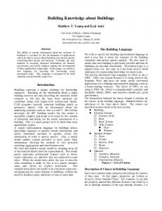
SYSTEM EVALUATION A three-storey building model (Figure 14) was constructed to help evaluate the capabilities of ARCABIM to process CDP workflows and conduct an audit against a selected RKM. The BCM schema described in this paper was used to generate the model view from the IFC version of the building model using a custom-built data serializer in conjunction with the open source BIMserver.
Figure 14: Test building model for system evaluation 16
Initially, a number of simple CDP workflows were used to extract specific information from the BCM and RKM to validate their correctness by manual comparison. Further tests were conducted using more complex CDP workflows to perform calculations based on parameters extracted from BCM and RKM and compare the result with manual calculations. ARCABIM was able to process all test CDP workflows correctly with results matching that of manual calculations. Figure 15 and Figure 16 show screenshots of the ARCABIM system. For the UT scenario example, it took approximately 6 hours to model a group of 8 different CDP workflows (including sub-processes) with approximately 80 activities in total, excluding any CDP for interfacing with external simulation tools. The process may take longer for someone who is unfamiliar with BPMN or its modelling tool. Although it may seem like a lot of effort to describe such a simple scenario, these CDP workflows are reusable once developed. As mentioned earlier in this paper, a library of standard CDP workflows can potentially be developed by an institution of engineers and published as the industry best practice procedures for a particular design discipline. For evaluation purposes, approximately 350 lines of RKM representing a small part of C/VM2 document were also encoded. It is estimated that the entire C/VM2 may need more than 2,500 lines of RKM to represent.
Figure 15: Screenshot of a CDP workflow representation in ARCABIM
CONCLUSION This paper has described a practical method, developed as part of the current research, to automate manual compliant design procedures (CDPs) using an open standard executable workflow model that can be described graphically in BPMN. The use of an open standard graphical language to describe CDPs makes them relatively easy to model and maintain with a set of guidelines. This method essentially allows a human designer to retain the responsibility of specifying design procedures that lead to certain compliance paths, and for a machine to execute those procedures accurately and consistently in a computing environment. The current research sets out to represent performance-based regulatory knowledge in an open standard format that is amenable to computer processing as well as being independent of the compliance audit system. The compliance audit framework developed in the current research has the capabilities of executing and processing open standard BPMN-compliant CDP workflows. The framework also uses the ISO-standard BIM representation to convey building design information while allowing supplementary human input and interfacing with external computational tools to enable processing of qualitative performance-based requirements. 17
Figure 16: Screenshot of a CDP workflow execution in ARCABIM To illustrate the CDP modelling and RKM encoding process, a performance-based fire engineering design scenario prescribed by the C/VM2 document of the building code of New Zealand has been selected due to its unique approach to compliance, which allows for interfacing with external computational or simulation tools. Lookup data, mathematical equations and rules, including those embedded in regulatory texts, can be formalised and represented in RKM as illustrated. A prototype system, ARCABIM, based on the framework that utilises the process described in this paper has been developed and tested for correctness using a BCM representing a simple three storey building with a range of CDP workflows and RKM representation of the C/VM2. The tool has been able to process all of the workflows and execute the embedded instructions correctly to produce results that match that of manual calculations. Further evaluation of the efficiency and effectiveness of the approach using a range of building types and comparing the result with a manual fire engineering design is planned for future work. An investigation into the use of a more generic open standard representation for legal documents that is currently being standardised by OASIS (Organisation for the Advancement of Structured Information Standards), an international consortium of open standards organisation (Athan et al., 2013), is also potential future work. The open standard approach for representing CPDs and regulatory knowledge for compliance audit presented in this paper is practical, relatively easy to implement, and is scalable for other types of regulatory document and standards as well as non-regulatory specifications. Therefore, we strongly advocate its adoption as an industry standard method of automating compliant design procedures to guide the compliance audit process.
ACKNOWLEDGEMENT This research receives funding assistance from the New Zealand Building Research Levy.
18
REFERENCES Athan, T., Boley, H., Governatori, G., Palmirani, M., Pasckhe, A., and Wyner, A. (2013). OASIS LegalRuleML. In The International Conference on Artificial Intelligence and Law. Rome, Italy. Beetz, J., and van Berlo, L. (2010). bimserver.org - An Open Source IFC Model Server. In Proceedings of CIB W78 International Conference, pp. 1–8. Cairo, Egypt. Clayton, M. (2013). Automated Plan Review for Building Code Compliance Using BIM. In Proceedings of 20th International Workshop: Intelligent Computing in Engineering (EG-ICE 2013), pp. 1–10. Vienna, Austria. Retrieved from http://smartreview.biz/smartreview-tr001.pdf Dimyadi, J., and Amor, R. (2013). Regulatory Knowledge Representation for Automated Compliance Audit of BIM-based models. Proceedings of CIB W78 International Conference, pp. 68–78. Dimyadi, J., Clifton, C., Spearpoint, M., and Amor, R. (2014). Regulatory Knowledge Encoding Guidelines for Automated Compliance Audit of Building Engineering Design. In Proceedings of the ICCCBE/CIB W78, pp. 536–543. Orlando, Florida, USA. Ding, L., Drogemuller, R., Rosenman, M. A., Marchant, D., and Gero, J. (2006). Automating code checking for building designs - DesignCheck. In Proceedings of the CIB co-sponsored Cooperative Research Centre (CRC) for Construction Innovation’s Second International Conference - Clients Driving Innovation: Moving Ideas into Practice, pp. 1–16. Gold Coast, Queensland, Australia. Eastman, C., Lee, J., Jeong, Y., and Lee, J. (2009). Automatic rule-based checking of building designs. Automation in Construction, 18(8), pp. 1011–1033. doi:10.1016/j.autcon.2009.07.002 Evt, S. K., Khayyal, S., and Sanvido, V. E. (1992). Representing Building Product Information using Hypermedia. Journal of computing in Civil Engineering, 6(1), 10.1061/(ASCE)08873801(1992)6:1(3), pp. 3-18 Feijó, B., Krause, W. G., Smith, D. L., and Dowling, P. J. (1994). A hypertext model for steel design codes. Journal of Constructional Steel Research, 28, pp. 167–186. Fenves, S. J., Gaylord, E. H., and Goel, S. K. (1969). Decision table formulation of the 1969 AISC specification. University of Illinois Engineering Experiment Station. College of Engineering. University of Illinois at Urbana-Champaign, USA. Greenwood, D., Lockley, S. S. S., Malsane, S., and Matthews, J. (2010). Automated compliance checking using building information models. In The Construction, Building and Real Estate Research Conference of the Royal Institution of Chartered Surveyors. Paris, France. Retrieved from http://nrl.northumbria.ac.uk/6955/ Hietanen, J. (2006). IFC model view definition format. International Alliance for Interoperability, pp. 1–29. Retrieved from http://www.secondschool.net/one/IAI_IFC_framework.pdf Hjelseth, E., and Nisbet, N. (2011). Capturing normative constraints by use of the semantic mark-up (RASE) methodology. In Proceedings of CIB W78-W102 Conference, pp. 1–10. Sophia 19
Antipolis, France. International Code Council. (2007). SMARTcodes. Retrieved from http://web.stanford.edu/group/narratives/classes/08-09/CEE215/ReferenceLibrary/International Code Council %28ICC%29/SMARTcodes fact sheet 11-01-07.pdf ISO 29481-1. (2010). ISO 29481-1: 2010 Building information modelling - Information delivery manual. British Standards. Khemlani, L. (2005). CORENET e-PlanCheck: Singapore’s automated code checking system. AECbytes “Building the Future.” Retrieved November 15, 2012, from http://aecbytes.com/buildingthefuture/2005/CORENETePlanCheck.html MBIE. (2014). C/VM2 Verification Method: Framework for Fire Safety Design For New Zealand Building Code Clauses C1-C6 Protection from Fire, 4th ed. The Ministry of Business, Innovation and Employment. ISBN 9780478381641. New Zealand Parliament. (1992). Building Regulations 1992 - Schedule 1 The Building Code. Parliamentary Councel Office, Wellington, New Zealand. . Object Management Group. (2011). Business Process Model and Notation (BPMN), version 2, pp. 1–538. Object Management Group. Retrieved from http://www.omg.org/spec/BPMN/2.0/ Pauwels, P., Van Deursen, D., Verstraeten, R., De Roo, J., De Meyer, R., Van de Walle, R., and Van Campenhout, J. (2011). A semantic rule checking environment for building performance checking. Automation in Construction, 20(5), pp. 506–518. Elsevier. doi:10.1016/j.autcon.2010.11.017 Salama, D. M., and El-Gohary, N. (2011). Semantic modeling for automated compliance checking. Journal of Computing in Civil Engineering, pp. 641–648. Spearpoint, M. J. (2009). Comparative Verification Exercises on a Probabilistic Network Model for Building Evacuation. Journal of Fire Sciences, 27(5), pp. 409–430. doi:10.1177/0734904109105373 Spearpoint, M. J., and Dimyadi, J. (2007). Sharing Fire Engineering Simulation Data Using the IFC Building Information Model. In International Congress on Modelling and Simulation MODSIM07. Christchurch, New Zealand. Wade, C., Baker, G., Frank, K., Robbins, A., Harrison, R., Spearpoint, M., and Fleischmann, C. (2013). B-Risk User Guide and Technical Manual. BRANZ Study Report 282, Vol. 282. Judgeford, Porirua City, New Zealand: BRANZ Limited. Wible, R., Hnatschenko, M., and Widney, J. (2011). FIATECH AutoCodes Project. Retrieved from http://bimforum.org/wp-content/uploads/2014/06/AutoCodes-2.pdf Zhang, J., and El-Gohary, N. (2012). Extraction of Construction Regulatory Requirements from Textual Documents Using Natural Language Processing Techniques. Journal of Computing in Civil Engineering, pp. 453–460. American Society of Civil Engineers.
20