Computers and Mathematics with Applications 56 (2008) 1597–1603
Contents lists available at ScienceDirect
Computers and Mathematics with Applications journal homepage: www.elsevier.com/locate/camwa
Geometric compression of a quadrilateral mesh Ren Chen ∗ , Xiaonan Luo, Hao Xu Institute of Computer Application, Sun Yat-sen University, Guangzhou, 510275, PR China Key Laboratory of Digital Life, Sun Yat-sen University, Ministry of Education, PR China
article
info
Article history: Received 10 October 2007 Received in revised form 12 February 2008 Accepted 5 March 2008 Keywords: Geometry compress Zerotree coding Wavelets Subdivision Progressive transmission
a b s t r a c t A new progressive compression algorithm for arbitrary topology with highly detailed triangle meshes is proposed in this paper. We firstly parameterize the original triangle mesh to a regular quadrilateral approximation. A wavelet transform is then applied to the approximation to remove a large amount of correlation between neighboring vertices. Finally, we used low cost zerotree coding and subdivision based reconstruction to build a sequence of progressive models. Our method will greatly reduce the cost of transportation with acceptable quality loss as shown in the experimental results. © 2008 Elsevier Ltd. All rights reserved.
1. Introduction For 3D graphics visualization applications, objects and models are often represented using complex meshes in order to maintain a convincing level of realism [1]. Accordingly, the cost of storage and rendering of high resolution models can be significant. Progressive compression and transmission of complex models can be used to alleviate this problem. The challenge of graphics applications include mesh simplification, progressive representation and view-dependant rendering. In this paper, we present a solution to these challenges. We define progressive geometric compression using quadrilateral remeshing and the wavelet transform. A novel zerotree hierarchy for primal semi-regular quadrilateral meshes is also defined. Section 2 shows literature review and related work. Section 3 outlines the details of our method for mesh decomposition, including mesh parameterization, steps for simplification. We also give an effective zerotree construction method for quadrilateral meshes. Section 4 shows the results of this research. Section 5 summarizes the main concepts of this paper and proposes some possible future work. 2. Review of related work Subdivision is a popular geometric modeling method which is naturally suited to progressive compression, since it recursively generates smooth surfaces of arbitrary topology from control meshes. Each refinement step can be divided into two different stages. First, a topological operation performed whereby new vertices are added to the meshes and the meshes are split. Then the geometry of the mesh is changed by a smoothing operation. Substantial results have been reported in the last few years on surface simplification. Hoppe introduced the concept of progressive mesh as a multi-resolution framework to represent triangular meshes based on edge collapse and vertex split [2]. Bartels and Samavati have introduced reverse subdivision rules to produce a multi-resolution presentation [3]. ∗ Corresponding author at: Institute of Computer Application, Sun Yat-sen University, Guangzhou, 510275, PR China. E-mail addresses:
[email protected] (R. Chen),
[email protected] (X. Luo). 0898-1221/$ – see front matter © 2008 Elsevier Ltd. All rights reserved. doi:10.1016/j.camwa.2008.03.023
1598
R. Chen et al. / Computers and Mathematics with Applications 56 (2008) 1597–1603
Fig. 1. Surface reconstruction of a technical data set in [17]: original mesh shaded (top left) and as wireframe (bottom left), regular quadrilateral remesh (bottom right) and reconstructed tensor product B-spline surface (top right).
Lounsbery first introduced wavelet transform into subdivision schemes [4]. But Lifting wavelet representations are among the most efficient multi-resolution method and also some researchers have described methods to simplify surfaces [5,6] and to represent or optimize the meshes [7–10]. There are two important operators defined in the lifting method: predictor operator and the update operator. We will see how these two operators work in Section 3. It is well known from image coding that wavelet representations are very effective in decorrelating the original data [11–13], greatly facilitating subsequent entropy coding. In essence, coarser level data provides excellent predictors for finer level data, leaving only generally small prediction residuals for the coding step. For tensor product surfaces, many of these ideas can be applied in a straightforward fashion [12]. However, the arbitrary topology surface case is much more challenging. To begin with, wavelet decompositions of general surfaces were not known until the pioneering work by Lousbery [4]. These constructions were subsequently applied to progressive approximation of surfaces [14] as well as data on surfaces. Some of the best wavelet based progressive coders are based on zerotree [15,16]. They effectively exploit the fact that wavelet coefficients at finer scales tend to be smaller in magnitude than coefficients at coarser scales in the same region. A zerotree coder encodes the location of coefficients below a certain threshold in subtrees. Standard zerotree coders for images are based on a dual formulation, i.e. coefficients are associated with faces. For primal hierarchical mesh decompositions using face splits (e.g. quadrisection of triangles) the data however lives at vertices, not faces. We show in Section 3.3 how to build zerotree coders for primal hierarchies. 3. Remeshing and compression 3.1. Remeshing and parameterization Our algorithm accepts an arbitrary connected regular quadrilateral mesh as input. Firstly we compute a smooth global parameterization using the method introduced by Horman [17] shown in Fig. 1. It allows us to compute successive adaptive regular quadrilateral approximations from an arbitrary input triangle mesh. These regular approximations can be subsequently wavelet transformed and progressively compressed using zerotree coding. The coarsest level connectivity can be encoded using a standard non-progressive mesh encoder [6]. The decoder may produce intermediate approximations from any prefix of the bitstream. 3.2. The wavelet transform The wavelet transform replaces the original mesh with a coarser mesh and a sequence of wavelet coefficients expressing the difference between successive levels. The wavelet transform can remove a large amount of correlation between neighboring vertices. The distribution of wavelet coefficients is centered around zero and their magnitude decays at finer levels with a rate of decay related to the smoothness of the original surface. This behavior of the magnitude of wavelet coefficients is the key to progressive coding and justifies the choice of the zerotree coder for the bit encoding of coefficients. By applying a quadrilateral subdivision scheme we can easily subdivide a mesh to a denser one. Each face is split into four new faces. The simplification process will just act in a reverse way, joining four faces into a new one and eliminating redundant points. Our method for constructing the wavelet transform requires three steps: vertex split, prediction and update.
R. Chen et al. / Computers and Mathematics with Applications 56 (2008) 1597–1603
1599
Fig. 2. For each even point (black), all surrounding white points belong to the odd group. It’s the same for the odd points.
Fig. 3. Vertex split. Start from the gray point at the middle left, the arrows point to the next points to be processed.
Fig. 4. Masks for vertex prediction.
Vertex split. In this phase, the whole point set will be divided into two subgroups. Lazy wavelet is the simplest method to split original point set. Split(C j ) = (Evenj , Odd ) = (cj−1 , dj−1 ). ( j−1 j Evenj : ci = c2i So we get j−1 j j Odd : di = c2i+1 . j
(1) (2)
We can easily divide the whole point set after remeshing into two groups as shown in Figs. 2 and 3. There are two type of eliminating vertex we can see from Fig. 2. Point A is related to a coarser face, Point B is related to a coarser edge. Prediction. Regular quadrilateral mesh after remeshing will have subdivision connectivity similar to the original mesh. According to the classic lifting method, odd vertices will be predicted from even vertices. Then the difference ej−1 is determined using following equation, where the operator P calculate the predict value. ej−1 = Odd − P (Evenj ) j
= dji−1 − P(cij−1 ) = C2j i+1 − P(C2j i ).
(3)
Iteratively performing this process will give a sequence as follows: cj = {cj−n , ej−n , ej−n+1 , . . . , ej−1 }
(4)
R. Chen et al. / Computers and Mathematics with Applications 56 (2008) 1597–1603
1600
Fig. 5. A coarser face is the parent of four finer faces.
mn1−1 = mn1−1 − Pe (vn2−1 , vn7−1 , vn12−1 , vn17−1 )
= mn1−1 − α(7n−1 + vn12−1 ) − β(2n−1 + vn17−1 )
mn0−1 = mn0−1 − Pf (vn0−1 , . . . , vn3−1 , vn5−1 , . . . , vn8−1 , vn10−1 , . . . ,n−1 , vn13−1 , vn15−1 , . . . , vn18−1 )
= mn0−1 − σ(vn0−1 + vn3−1 + vn15−1 + vn18−1 ) − ν(vn6−1 + vn7−1 + vn16−1 + vn17−1 ) − µ(vn1−1 + vn2−1 + vn5−1 + vn8−1 + vn10−1 + vn13−1 + vn16−1 + vn17−1 ).
(5)
Here we use Kobbelt subdivision mask [7] as the prediction operator P. We divide P to Pf and Pe in order to handle the prediction on face vertex and edge vertex separately. For example, face vertex mn0−1 and edge vertex mn1−1 in Fig. 4 can be calculated by surrounding vertices using formula (5). Update. Eliminating odd vertices will definitely lose some geometric features. To reduce the error, we update the even vertices locally after the elimination process. To simplify the computation, we use the most immediate neighboring coefficients for update that satisfy: K P i=0
L P
j
ci
=
K
i=0
j−1
ci L
.
(6)
K and L are the size of Even(n) and Even(n − 1). For regular quadrilateral mesh, K :L satisfy 5:2. So here is the update operator U : vn12−1 = vn12−1 + A
7 X
mni −1 .
(7)
i=0
From (6) and (7), we get A = 1/10. The reconstruction scheme can be quickly built from the above description: (1) Undo Update: Evenj−1 = Evenj−1 + U (dj−1 ) (2) Undo Predict: Odd = P(Evenj ) + ei j
j−1
= P(cij−1 ) + eji−1 .
(8)
Merge: Mj+1 = Merge(Even , Odd ). j
j
Using the scheme above we can reconstruct the original dense mesh without loss. But for efficiency considerations, we hope to reduce the storage cost with acceptable visual loss. So we introduce zerotree coding to achieve this. 3.3. Zerotree coding compression We present a new construction method of the zerotree coding here which is motivated by Khodakovsky [18]. For images associates coefficients with a quadrilateral face and the trees follow immediately from the face quadtree while our transform is vertex based. The main insight is that while scale coefficients are associated with vertices, wavelet coefficients have a oneto-one association with edges or faces of the coarser mesh. Vertices do not have a tree structure, but the edges and faces do. Each edge and each face is the parent of four edges of the same orientation in the finer mesh as indicated in Figs. 5 and 6. Hence, each edge and face of the coarsest domain mesh forms the root of each zerotree; it groups all the wavelet coefficients of a fixed wavelet subband from its incident based domain faces. No coefficient is accounted for multiple times or left out by this grouping. There are two kinds of relation we may set up as indicated in Figs. 6 and 7. In each figure, we see the relations between edge and point between two neighboring levels. Each related quadtree is marked with different signs such as circle, matrix and triangle. For example, in the left of Fig. 6, the left edge in A points to four edges in B marked as 1, 2, 3, 4. The right side of Fig. 6 is the relations between points at successive levels. A black triangle vertex in A points to four blank triangles in B mark as 7. Fig. 7 shows another quadtree construction method. Since we prefer a balanced structure at the edge of the model, methods in Fig. 6 is better since it will preserve 3 child node while in Fig. 7 only 2 node will be reserved. The traditional zerotree algorithm consists of a number of passes with exponentially decreasing thresholds. In each pass we travel the tree and compare each node’s value to T0 . If the condition mets, this node is not important, we replace it with a sign and ignore its subtree. At each pass, significance bit is sent for each newly significant coefficient. Additionally,
R. Chen et al. / Computers and Mathematics with Applications 56 (2008) 1597–1603
1601
Fig. 6. A coarse edge (left) is parent to four finer edges of the same orientation (right).
Fig. 7. Another method to construct the zerotree structure.
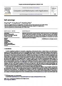
Fig. 8. Compression rate and distortion rate of bleck and face model.
refinement signs are sent for coefficients which became significant in an earlier pass. The decoder can reconstruct the geometry associated with any prefix of the bit stream by running an inverse wavelet transform on the coefficient bits seen so far. The decay properties of wavelet coefficients make their hierarchical tree organization the natural set structure. We use embedded zerotree wavelet algorithm (EZW) for encoding. Detailed description of EZW can be found in [15,16,19]. Also we can use another method for encoding such as SHIPT introduced by Said and Pearlman [20]. 2 2 Let T0 = 2blog2 (MAX(|Xi |))∗10 c/10 be the maximum magnitude of all coefficients. In the first pass the coder should send the locations of newly significant coefficients which are greater than T0 /2. Coefficients are organized into canonical sets as indicated in Figs. 6 and 7 such that a few set-based significance tests can enumerate the locations of the relevant coefficients. Let T0 = T0 /2 after the first decoding and repeat the previous process. The node which has already been reverted must do so using the new measurement set. This can ensure that the reverted value approaches the real value. Finally, we use T0 /2 to replace the node that cannot be reached during the compression process. Output of the zerotree coding can be compressed further through arithmetic coding, such as Huffman encoding [21], which allows for a fractional number of bits per symbol. An arithmetic coder takes advantage of this [22]. 4. Experimental results Obviously, refining the coarsest mesh M0 without adjusting using wavelet coefficients will not lead to the original mesh. Fig. 9 show the errors between successive levels. In our algorithm, more quantization passes will lead to lower compression
1602
R. Chen et al. / Computers and Mathematics with Applications 56 (2008) 1597–1603
Fig. 9. M3–M0 shows the Compression process. The second row indicates the errors between different successive levels (all errors are multiply by 3 to make them significant).
Fig. 10. Reconstructed bleck/face model with 2, 4, 6 quantization passes. From left to right are original model. Reconstructed model with errors compressed by 2, 4 and 6 rounds of quantization passes.
R. Chen et al. / Computers and Mathematics with Applications 56 (2008) 1597–1603
1603
Table 1 Size of models with 2/4/6/8/10/12 round of quantization passes Model name
Face Bleck
Size of ori. mesh
259 KB 1019 KB
Size of base mesh
2.10 KB 6.59 KB
Size of wavelet coefficients 2 pass
4 pass
6 pass
8 pass
10 pass
12 pass
2.64 KB 8.07 KB
4.66 KB 14.8 KB
7.28 KB 23.7 KB
9.54 KB 32.0 KB
11.5 KB 39.5 KB
13.3 KB 46.1 KB
rate and better visual quality. Most values of the vertices having been transformed into coefficients which can be highly compressed. Table 1 shows how storage size keeps increasing after 2/4/6/8/10 quantization passes. The compression rate is reduced to 0.036 after 6 round of quantization pass. Fig. 8 is the rate-distortion curves with different passes. Compress rates decrease when apply more quantization pass, but the distortion rate will firstly decrease then increase during this procedure. We find 6 passes is the best choice for visualization while 4 passes is better considering both visualization and performance requirement. Regarding the incrementing of distortion rate after 6 passes, we consider it is caused by the value we used to replace the unreached node during the compression. Fig. 10 show the reconstructed models with 2/4/6 quantization passes. 5. Conclusion and future work We have described a fast and easily implemented progressive compression method based on quadrilateral remeshing, wavelet transform, and zerotree coding. From the experimental results, it’s a fast and efficient method for multi-resolution analysis and application. Depending on different significant passes, our method will be suitable for high visual quality requirement and low bandwidth situations. Possible future work includes constructing more efficient prediction and update operator, and constructing more efficient ways to represent vector valued coefficients. Acknowledgements Supported by the National Science Fund for Distinguished Young Scholars (No. 60525213) and the Key Project (No. 60533030) of NSFC, 973 Program of China (No. 2006CB303106), the Cultivation Fund of the Key Scientific and Technical Innovation Project (NO706045) and RFDP (No. 2006352404111065) of Ministry of Education of China, and the Key Project of Guangzhou Municipal Government (No. 2006Z1 - D6131). References [1] M. Levoy, The Digital Michelangelo Project, in: Proceedings of the 2nd International Conference on 3D Digital Imaging and Modeling, October, 1999. [2] H. Hoppe, Progressive meshes, in: Computer Graphics Proceedings, Annual Conference Series, ACM SIGGRAPH, New Orleans, Lousiana, 1996, pp. 99–108. [3] R.H. Bartels, F.F Samavati, Reversing subdivision rules: Local linear conditions and observations on inner products, Journal of Computational and Applied Mathematices 119 (1–2) (2000) 29–67. [4] M. Lounsbery, T.D. Derose, J. Warren, Multiresolution analysis for surfaces of arbitrary topological type, ACM Transactions on Graphics 16 (1) (1997) 34–73. [5] P. Schroder, W. Sweldens, Spherical wavelets: Efficiently representing functions on the sphere, in: Computer Graphics Proceedings, Annual Conference Series, ACM SIGGRAPH, Los Angeles, California, 1995, pp. 161–172. [6] E. Catmull, J. Clark, Recursively generated B-spline surfaces on arbitrary topological meshes, Computer Aided Design 10 (6) (1978) 350–355. [7] L. Kobbelt, S. Compagna, J. Vorsatz, et al., Interactive multi-resolution modeling on arbitrary meshes, in: Computer Graphics (Proceedings of SIGGRAPH’98), pp. 105–114. [8] R. Pajarola, C. DeCoro, Efficient implementation of real-time view-dependent multiresolution meshing, Visualization and Computer Graphics, IEEE Transactions on Graphics 10 (3) (2004). [9] C. Touma, C. Gotsman, Triangle Mesh Compression, Graphics Interface’98, pp. 26–34. [10] D. Zorin, P. Schroder, W. Sweldens, Interpolating subdivision for meshes with arbitary topology, in: Computer Graphics Proceedings (SIGGRAPH 96), pp. 189–192. [11] S.D. Riemenschneider, Z. Shen, Wavelets and pre-wavelets in low dimensions, Journal of Approximation Theory 71 (1) (1992) 18–38. [12] R.A. Devore, B. Jawearth, B.J. Lucier, Surface compression, Computer Aided Geometric Design (1992) 219–239. [13] G. Davis, A. Nosratinia, Wavelet-based image coding: An overview, Appied Computational Control, Signals, and Circuits 1 (1) (1998). [14] P. Cignoni, C. Rocchini, R. Scopigno, Metro: Measuring error on simplified surfaces, Computer Graphics Forum 17 (2) (1998) 167–174. [15] A. Said, W. Pearlman, A new, fast, and efficient image codec based on set partitioning in hierarchical trees, IEEE Transaction on Circuits and Systems for Video Technology 6 (3) (1996) 243–250. [16] J Shapiro, Embedded image-coding using zerotrees of wavelet coefficients, IEEE Transactions on Signal Processing 41 (12) (1993) 3445–3462. [17] K. Hormann, G. Greiner, Quadrilateral Remeshing, in: Proceedings of Vision, Modeling and Vizualization, 2000. [18] A. Khodakovsky, P. Schroder, W. Sweldens, Progressive geometry compression, in: Proc. ACM SIGGRAPH’00, ACM Press, New York, 2000, pp. 271–278. [19] G. Davis, S. Chawla, Image coding using optimized significance tree quantization, in: Proceedings Data Compression Conference, 1997, pp. 387–396. [20] A. Said, W. Pearlman, A new, fast and efficient image codec based on set partitioning in hierarchical trees, IEEE Transactons on Circuits and System, Video Technology 6 (1996) 243–250. [21] D.A. Huffman, A method for the construction of minimum redundancy codes, Proceedings of the Institute of Radio Engineers 40 (1951) 1098–1101. [22] Jin Kook Kim, Jong Beom, Ra: A real-time terrain visualization algorithm using wavelet-based compression, Visual Computer 20 (2–3) (2004) 67–85.