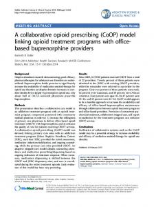
Int J Adv Manuf Technol (2007) 34:1224–1235 DOI 10.1007/s00170-006-0677-1
ORIGINAL ARTICLE
Conception and implementation of a collaborative manufacturing grid Zhi Li & Xianlong Jin & Yuan Cao & Xiaoyun Zhang & Yuanyin Li
Received: 9 August 2005 / Accepted: 20 April 2006 / Published online: 18 August 2006 # Springer-Verlag London Limited 2006
Abstract Computer supported collaborative work (CSCW) technology and grid technology are integrated to solve the resource-sharing problems in collaborative design, analysis, and manufacture. The application of grid technology in collaborative manufacturing is presented. Function requirement of collaborative manufacturing grid (CMG) is analyzed for product design, analysis, and manufacture. A concept of the CMG is put forward, and its corresponding architecture is set up based on grid middleware. Grid services in the CMG are realized based on the Globus Toolkit. A grid portal of the CMG based on the Web is developed, and advanced graphical interfaces are provided for potential users. Functions of workflow based on CMG are presented, and its management is discussed for automatic workflow creation and execution in a grid environment. A prototype system is established via a case study of the sightseeing lift. It validates the resourcesharing and cooperative work in the CMG. Keywords Collaborative manufacture . Grid . Architecture . Services . Portal . Workflow Abbreviation CMG Collaborative manufacturing grid
The research was fully supported by the National High-Tech. R&D Program of China (Project No. 2002AA104520) and the National Natural Science Foundation of China (Key Program: No. 90412010). Z. Li (*) : X. Jin : Y. Cao : X. Zhang : Y. Li School of Mechanical and Power Engineering, Shanghai Jiaotong University, ROOM 602, Mechanical Engineering Building, No.1954, Huashan Road, Shanghai 200030, People’s Republic of China e-mail:
[email protected]
1 Introduction Product manufacture is typically group work. Manufacture in this case includes design, analysis, and manufacture of product. Group members have individual work and collaborative work. The individual work is the task that each group member is assigned and should have finished respectively, while the collaborative work is the correlative problems existing among the group members and cannot be divided into independent individual works. Generally, these problems are called “interface problems”. Contradiction and conflict will inevitably occur in interfaces. If they cannot be found and harmoniously resolved in time, they will cause rework and loss [1]. Traditional CAD/CAE/CAM systems only support concrete tasks that should be completed after the work is divided, but cannot solve the interface problems among the members. These problems mainly depend on interviews or certain communication tools for discussions and then need to be resolved. But these methods cannot provide timely consultation and sufficiently discussion. Therefore, a large, complex, geographically distributed engineering project will generally be confronted with many interface problems, which leads to some work to be repeated inefficiently. Advances in processor and computing technology have led to a common practice of CAD/CAE/CAM collaboration being assisted by using collaborative tools to establish a computer supported collaborative work (CSCW) environment. CSCW is one of the main technologies in the collaborative design, analysis, and manufacture field. Group members can use CSCW to exchange their ideas, discuss their results, find contradictions and conflicts, and then harmonize and resolve them in time. By doing so, rework is reduced. Consequently, it enhances efficiency and quality of collaborative work [2, 3].
Int J Adv Manuf Technol (2007) 34:1224–1235
A collaborative network based on product design, analysis, and manufacture is now a common practice for innovation and technology breakthroughs. This is enabled by the technologies in CSCW, which requires members to collaborate with the professionals with multidisciplinary knowledge in the process of product development. Currently, more and more people are interested in collaborative manufacture. There are many prototype systems of collaborative manufacture and some of them are already commercialized [4, 5]. Members participating in collaborative manufacture are dispersed geographically, and equipment condition used by them is also diversiform. Therefore, a practical collaborative manufacturing system must be running in a geographically distributed heterogeneous environment. This includes data transfer, tools integration, and cross-platform interactive interfaces [6]. But distributed resources sharing and remote collaborative manufacturing in LAN or WAN environment should be realized for building up applicable collaborative manufacturing system. Grid technology becomes one of the best choices for collaborative problems owing to its characteristics and application patterns. The grid connects geographically distributed various computers, including high-performance computers, workstations and PCs, databases, and all kinds of other equipment through a network. This will form a virtually high-performance computing environment that is transparent to the user, and realize high-performance computation, resources share and collaborative work. Its application includes scientific and engineering computation, information service, data service, collaborative engineering, etc. [7]. The grid computing framework has developed as an infrastructure of connecting and unifying various remote resources. Its basic characteristics are resource sharing and the elimination of resource separation, but not scale of massiveness [8]. We can build up a global grid, regional grid, enterprise grid, home grid and personal grid according to our requirements, so the application of grid computing will be very extensive. At present, IT corporations (IBM, HP, Sun, etc.), automobile manufacturers (GM, Ford, etc.), aviation industry and many governments have started to study internal relation of collaborative manufacture and grid technology. Zhiwei Xu et al. looked at CSCW from a gridcomputing viewpoint, and pointed out the trend of network computing and outline its implications and new CSCW requirements [9]. Therefore, we put forward an application of grid technology in collaborative manufacturing. The rest of the paper is organized as follows: In Section 2, we outline concrete function requirements of collaborate manufacture in grid environment, present the concept of collaborative manufacturing grid (CMG), and build up the architecture of CMG. In Section 3, we discuss the realizing technology of grid services in the CMG based on Globus Toolkit 3.0 (GT3), and describe some concrete grid services.
1225
In Section 4, we develop relative grid portal of the CMG with an emphasis on the way that the portal server interacts with remote grid services. In Section 5, we present functional requirements of workflow in the CMG and discuss workflow management in a grid environment. In Section 6, we discuss the prototype system of the CMG via an example of the sightseeing lift. Finally, we draw a conclusion in Section 6. 2 Conception of CMG 2.1 Function requirements of CMG CMG requires high computational capacity, mass storage capacity, joint participation and real-time interaction among members in a geographically distributed heterogeneous environment. It utilizes open, dynamics and real time of grid system. Therefore, in order to to use sufficiently existing computational resources and economize costly expenses of various CAD/CAE/CAM software, the concrete functions of CMG can be described in the following features: (1) Management of manufacturing process. Manufacturing process acquires design, analysis, and manufacturing tasks by means of customer requirement. These tasks are divided into many subtasks. Customer and multiple enterprises compose a virtual organization (VO). The members of the VO jointly take part in functional analysis, principle design, structure design, structure analysis, manufacturing of product in different processes. Each member is assigned to individual work and the corresponding responsibility. At the same time, the entire manufacturing process of product is monitored. (2) CAD collaboration. CAD control module of collaborative manufacture provides appropriate integration interface when each member enters the CMG platform and participates collaborative design by selecting different CAD systems. It also provides consultation of product design strategies in the intelligent design process of a product. Each member can call corresponding models, data, rules and experienced knowledge for intelligent design of product or component by means of CAD software and developing module of product family. (3) CAE collaboration. CAE control module of collaborative manufacture provides an appropriate integrating interface when each member enters the CMG platform and participates collaborative manufacture by selecting different CAE system. The analysis engineers can acquire geometric models of product or component through downloading from a Web browser, create simulation model at the client and upload the simulation model to a server through the Web. The analysis parameters of a product or component are set in a Web browser, and a simulation job is submitted from the Web
1226
browser. Job running states can be viewed from clients. Finally, simulating results are visualized and are published on a Web server. This also provides consultation of simulating and optimizing strategies. These strategies can acquire the CAE model from the CAD model through CAD/CAE format conversion interface. They also can execute automatic simplification and intelligent engineering analysis by means of calling analysis data and existing knowledge, experience and rules of product. (4) CAM collaboration. CAM control module of collaborative manufacture provides appropriate integrating interface when each member enters the CMG platform and participates collaborative manufacture by selecting different CAM system. It controls the generation of a tool path and the post-processing of a NC program to extend CAD collaboration to the collaborative manufacturing in machining. It also provides consultation of manufacturing strategies by means of calling manufacturing data and existed knowledge, experience and rules of product. The manufacturing engineers can acquire geometric models of a part, component, and product through downloading from a Web browser, create manufacturing model at the client, and send CAM code to a remote machining cell through the Internet. The manufacturing parameters of a product or component are set in a Web browser, and the manufacturing job is submitted from a Web browser. At the same time, we can monitor job-running states from clients. (5) Data format conversion. Generally, there are two alternatives for the data exchange among different CAD/CAE/CAM systems; one is direct database conversion and the other is through neutral data file. If each member uses different CAD systems, the corresponding design result is issued according to the specific CAD system. When another member requests a design file of different format, CMG platform will provide automated conversion of file format from existed format to the required one according to member rights. The involved file format can be used for Unigraphics, Pro/ENGINEER, CATIA, AutoCAD, IGES 2D&3D, and VRML (Virtual Reality Model Language), etc. In addition, simplified CAE model also can be converted from one file format to another. (6) Model base. It includes different version of geometric model and simulation model of current design task in all phases, and case model of product family. Distributed access, call and management of model are realized. (7) Database. It includes user management, design requirement of product, functional decomposition, design process, subtask of design, structural configuration of product, management of CAD/CAE/CAM model, running condition of simulation
Int J Adv Manuf Technol (2007) 34:1224–1235
job, release of design result and execution of manufacturing task, etc. It provides some universal operations, for example, searching, appending, modifying and deleting, etc, of all kinds of information. (8) Knowledge base. The knowledge base includes design, analysis and optimization strategies of product. It also includes design and analysis knowledge of product family. It realizes some operations, including appending new knowledge and modifying or deleting existed knowledge. (9) Interactive tools. These tools provide some accessorial tools for all participating members of the CMG platform. These tools can reinforce real-time communications and collaborations across the intranet or Internet among members. They also provide the coordination of video, audio, text chat, white board, desktop sharing and file transfer, etc., to form a seamless multimedia interactive environment.
2.2 Concepts of CMG CMG is a manufacturing platform of cooperative completing product design, analysis, and manufacturing task. It gathers geographically distributed, heterogeneous computational resources, storage resources, equipment resources, data resources and human resources to form a dynamic virtual organization (VO) for the collaborative task of the same product in WAN environment. Customers, designers, and CAE/CAM engineers in the VO undertake corresponding responsibility and individual task, respectively, under virtual collaborative environment based on the grid. Design, numerical simulation, and manufacture can be coordinately, interactively, and collaboratively executed. The basic characteristics of CMG include customer participation, multiple enterprise union, carrying collaborative design, analysis and manufacture under distributed heterogeneous environment. Customers, designers, and engineers of different enterprise may be distributed in different geographical locations. They usually use different design/analysis/manufacture tools to execute remote collaborative task based on the Web. They also discuss and modify the task plan in a virtually shared grid environment again and again. Finally, product design, analysis, and manufacture are completed at the quickest speed and at the best quality. All participators based on CMG are able to understand whole task plan in time. They can comprehend evolving status of manufacture process at any moments. They also can dynamically acquire information about design model, simulation model, simulation result, and manufacturing model in every stage. The manufacture resource can be conveniently shared. Finally, the CMG effectively realizes intelligent manufacture and collaborative communication among members in the VO.
Int J Adv Manuf Technol (2007) 34:1224–1235
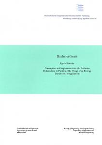
2.3 Architecture of CMG Distributed technologies, such as CORBA, J2EE, DCOM, are adopted to realize distributed computation in many existing collaborative manufacturing systems. Though these technologies may construct various distributed application systems, these systems are only limited in a customized static domain. For example, the hardware and software environment of each application system is basically changeless. If the static domain is changed, this will affect the resource sharing and application systems, and we must reconstruct all application systems manually. To automatically adapt dynamically changing domain and achieve all resource sharing, further research is required. Web service technology only supports peer-to-peer transaction processing, but it doesn’t support multi-transaction model. Therefore, Web services are not suitable for constructing manufacture process of multi-party collaboration. However, grid services are capable of resolving the above problems. They are combined with Web services and grid technology, and are suitable for realizing all resources sharing, cooperative interaction of multi-party participants, multiple communication modes (peer-to-peer, end-to-end, multibroadcast, etc.) and communication requirement (massive data transfer, stream data, group broadcast, etc.) in dynamical environment. Sharing grid resources include computational resources, storage resources, software resources, network resources, instrumentation resources and code repositories, etc. Resource sharing will lead to sufficiently utilize existed resources and reduce further invest expenses. Grid services are regarded as the extension of Web services. The greatest extension is that a grid service is a descriptive Web service and may be permanent or transient. Grid services include status information in services and can realize transient services by means of factory mechanism, but Web services do not include status information and can only realize permanent services, which are valid when starting container. In addition, grid services also adopt other mechanisms, such as notification, life management, change management, handle and resolver, etc. [10, 11]. CMG is an integrated virtual design, analysis, and manufacturing platform based on the grid, and includes the content of information integration, process integration and knowledge integration. Its architecture is shown in Fig. 1 and can be divided into four layers: resource layer, middleware layer, service layer, and portal layer. The resource layer includes all kinds of computational resources, storage resources, network resources, software resources (providing various CAD/CAE/CAM tools and database systems), and manufacturing resources (including model base, database, and knowledge base of the product, and machining equipment). The middleware layer is a series of tools and
1227
protocol software of GT3, and its function is to hide geographically distributed, heterogeneous characters of various resources in the resource layer and to provide transparent, coincident applying interface to service layer of grid application. Grid middleware is also called the “grid operation system”, and provides simultaneously user programming interface and developing environment of grid application services. Service layer provides various services for meeting the requirement of collaborative manufacture. Grid application developing engineers associate with CAD/CAE/CAM engineers and adopt existent grid environment and various tools to develop CAD/CAE/CAM application services and other collaborative manufacturing services. The portal layer is entry toolkits of CMG in Web pattern, which provides good interactive interface, coincident using mode and convenient usage to access grid resources for the user. Distributed grid resources are integrated by utilizing grid middleware and are encapsulated by grid application services. At the same time, CMG provides common services, such as resource management, monitor, security authentification, file transfer, batch job and so on. Various CAD/CAE/ CAM services are integrated by the grid portal for simplifying the complicated process of applying the grid. Developed grid interfaces are oriented to user management, manufacturing process management, online order, collaborative design, numerical simulation, result visualization, and collaborative manufacture, etc. They hide the intricate system operations in the CMG. Clients submit the requirement of manufacture through the Web, while users check the requirement and then submit a corresponding design task. Experienced knowledge and rules about design strategies and optimization analysis strategies can be acquired from the knowledge base by the inference engine. This design task can be divided into several subtasks, which are resubmitted and may collaboratively interact with one another. But some complicated intelligent designs of parts or components are completed by back-end intelligent design program. At the same time, CAE and CAM tasks can be completed. Here, collaborative CAM is composed of three parts: the generation of tool path, the post-processing of NC program, and the linkage to a remote machining cell. The generation of the tool path is based on the CAM statements of the API. The CAM statements support the subroutines necessary to create a milling tool path. For example, CAM modal setting, definition of cutting tools, management of tools’ library, extraction of tool information, generation of custom post-processor statements, assignment of the CAD geometry, generation of a tool path, and post-processing of a NC program. There is no single function that could be used to generate the tool path of an existing geometry, to output a CL file, and to post-process the NC program in the CAD/CAM system that was adopted. Therefore, customized CAM functions were developed in order to link to a remote machining cell.
1228 Fig. 1 Architecture of collaborative manufacturing grid
Int J Adv Manuf Technol (2007) 34:1224–1235
User Manage ment
Portal Layer
Process Control
Process Control & Manage Service
Service Layer
User Management Service
Online Order Service
Display Result Service
Grid Security
Middleware Infrastructure Layer
File Transfer Service
Data format Transform Service
CAD Software Service
Globus Resource Allocation Manager
Grid FTP Service
Resource Layer
Compute Resource
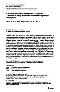
In addition, CMG provides some managing functions for the user. User management services include user register, user authentification, user rights and management of user information, etc. Job management services are responsible for execution of user job, and can be divided into job interactive management, job state management, and job execution management. (1) Job interactive management may complete interaction of user jobs and task programs among Web browser, portal server, grid server and nodes. (2) Job state management is used for user to examine and manage the job states. (3) Job execution management is to manage entire execution process of job program. 2.4 Testbed of CMG According to the architecture of CMG, a testbed of CMG is set up to support the application for product design, analysis, and manufacture within a mass customization environment. Its framework is shown in Fig. 2. This framework includes three parts: client, Web server, and application grid. The client is used for the client to browse the portal page of CMG and to set and submit a job. The Web server consists of portal server and data server. The portal server is responsible for interaction and communication among users, data server, and grid server. The data server provides the function of data store and various data operations. The application grid receives a application request, interprets and
Storage Resource
Multi-Party Collaborate CAE
Multi-Party Collaborate CAD
Online Order
Multi-Party Collaborate CAM
Display Result
Model Service
Data Service
Knowledge Service
CAE Software Service
CAM Software Service
Job Management Service
Metacomputing Directory Service
Global Access to Secondary Storage
Globus Replica Management
Network Resource
Software Resource
Design Resource
Manufacturing Resource
decomposes the request as a group of concrete jobs, and allocate the different job to the corresponding grid node.
3 Realizations of CMG services Open grid service architecture (OGSA) of GT3 is adopted in developing the process of CMG services. Its internal services solve many problems, including security, information infrastructure, resource management, communication, error detection, and portability, etc. As implementations of these newly constructed services begin to appear, OGSA has become a more useful service-oriented architecture [10, 11]. Grid services are a basic concept of OGSA and are specific Web services. They provide a group of welldefined interfaces and conform specific conventions (expressed using WSDL). The interface of grid services settles some problems, such as discovery, instance creation of dynamic service, lifetime management, notification, and manageability, etc. Grid services are always deployed within different operation systems, for example, Linux, Windows, Solaris and AIX, etc. OGSA also provides a grid security mechanism to insure that all communications among services are safe. According to the structure model of GT3 software, we establish frameworks of server and client for collaborative manufacture and CAD/CAE/CAM software and adopt usual distributed computing programming model, namely proxy-stub model. We design server and client program flowcharts of collaborative manufacture and CAD/CAE/
Int J Adv Manuf Technol (2007) 34:1224–1235 Fig. 2 Framework of collaborative manufacturing grid test bed
1229
Web Server Data Server
Portal server
Client
JDBC
JSP/Servlet
Browser
Database
File System
Transfer Design Model by GridFTP/GASS ODBC
Display JSP Webpage
Java Bean
User Management
User Management
Process Control
Process Control
JDBC
VRML Model
Grid Server CAD Grid Node 1
Extraction & Store of Data & File
Online Order
Create & Execute Services
Internet
Collaborative CAD
Monitor Collaborative Task & Process
Collaborative CAE
Extraction & Store of Other Information
Collaborative CAM
Edit Command Stream File
Display Result
Division of task
Grid Nodes
Search Services
CAX Grid Service 0 Grid Instance 1 Grid Instance 2
CAE Grid Node 1 Intranet
CAM Grid Node 1 ……
Inference Engine
…… XML
Grid Instance n
Knowledge Base Server
……
Application Grid Inference Engine
CAM software application services (permanent or transient), and write the program corresponding code. Finally, these grid services are deployed on OGSA container and tested. Workflow of the calling service is shown in Fig. 3, and its executing process conforms to the following order: (1) Service providers publish services on a service proxy. (2) Service requestors search a requisite service from the service proxy. (3) The service requestors call the corresponding service according to the searched service address. (4) The service providers respond the service requestor’s calling and create service instances. (5) The service providers return addresses of the service instances to the service requestors. (6) The service requestors and the service instances are bound.
Service Proxy
Ca ll
Re tu rn
Search
Instance 1
…
Instance n
Service Requestor 1
…
Service Requestor n
Binding
Create
Binding
Distribute
Service Provider
Fig. 3 Workflow of calling collaborative manufacturing services
Program design of CMG services must conform to the distributed computational programming model. It includes server programming and client programming, which are loose-coupled. The relation between them is realized by a Web Services Description Language (WSDL) document. As a service provider, when we develop grid services, WSDL document of the corresponding grid services should be provided. We describe interface of services in detail, calling methods of services and binding condition between service calling and communication protocols of bottom layer in this WSDL document. Stubs of calling service can be created after clients acquire the WSDL document. Consequently, users will utilize these stubs to call services. At the same time, the WSDL document also provides possibility for the separation between calling of upper layer service and communication protocols of bottom layer. In addition, service providers may provide multiple binding methods for service calling and communication protocols of bottom layer. Clients may select one of the binding methods to complete the service calling. Sometimes the selection of this binding can be deferred until the calling service. General format of interface class of CMG: public interface NameCall { public void NameRun(para1,para2,...); ... } General format of realizing class of CMG: public class NameCallImpl extends GridServiceImpl implements NameCallPortType { public NameCallImpl(){...}
1230
Int J Adv Manuf Technol (2007) 34:1224–1235
Table 1 Interface class and implementing class of CAD software and corresponding services
Table 3 Interface class and implementing class of CAM software and corresponding services
CAD software
CAD service interface class
CAD service implementing class
CAM software
CAM service interface class
CAM service implementing class
Unigraphics ProEngineer Catia Ideas SolidEdge SolidWorks
UnigraphicsDCall ProEngineerDCall CatiaDCall IdeasDCall SolidEdgeDCall SolidWorksDCall
UnigraphicsDCallImpl ProEngineerDCallImpl CatiaDCallImpl IdeasDCallImpl SolidEdgeDCallImpl SolidWorksDCallImpl
Unigraphics ProEngineer Catia Mastercam
UnigraphicsMCall ProEngineerMCall CatiaMCall MastercamMCall
UnigraphicsMCallImpl ProEngineerMCallImpl CatiaMCallImpl MastercamMCallImpl
public void NameRun(para1,para2,...) throws Remote Exception {...} ... } Currently, the developed grid services are based on function requirements of CMG and are shown in Tables 1, 2, 3 and 4.
4 Design of grid portal Grid Portal is an effective means of utilizing grid resources and provides high-end graphic interface for potential users. Its programming model is an extension of the J2EE programming model. It is used to integrate grid applications that leverage the rich set of grid portal capabilities in CMG, which include aggregation and integration of components into page hierarchies, flexible navigation, content and application aggregation, branding, customization, personalization, content management, document management, search, and so on. Figure 4 shows how a portal works in principle. The portal integrates the components within the CMG. All of a user’s applications are integrated by the portal and displayed in a single window, so that the end user gets a consistent view of many disparate systems within the CMG that has meaning to that user. This powerful capability enables the CMG to provide users with an integrated, consistent means of working with a complex grid of applications.
Grid applications in CMG often involve a complex process of collaborative manufacture. The end users include customers, designers, and engineers. They want to do by means of language of their scientific domain and run these applications without becoming experts on grid technology [12]. The users interact with the grid portal, and the portal interacts with various backend applications, aggregating them all for the users into a single browser window, the portal page. That is, the users interact with the application through a grid portal that records their choices for the application parameters. These application parameters are entered into grid execution workflow scripts that are authorized by a second group of scientists who understand how to compose grid services into distributed applications. Domain experts are the authors and maintainers of the basic service and tool components such as the simulation codes, manufacturing codes, and data filters that compose the basic elements of the manufacture. When the end-user applies directly grid services without grid portal, he commonly will meet some difficulty. Therefore, it is necessary to develop grid portals between users and grid services. The grid portals can hide complicated internal details of various grid resources. Here, users can use the grid system and acquire grid services by means of familiar user interface, consistent operation modes and high-efficient convenient access mechanisms. Consequently, the perplexing problems of using grid resources are resolved. In addition, grid portal should meet the requirements of ease of use for the user, security, portability, extensibility, independence and completeness, etc.
Table 2 Interface class and implementing class of CAE software and corresponding service CAE software
CAE service interface class
CAE service implementing class
LSDYNA PAMCRASH ANSYS NASTRAN MARC FLUENT
LSDYNACall PAMCRASHCall ANSYSCall NASTRANCall MARCCall FLUENTCall
LSDYNACallImpl PAMCRASHCallImpl ANSYSCallImpl NASTRANCallImpl MARCCallImpl FLUENTCallImpl
Table 4 Interface class and implementing class of format conversion and corresponding services File format
Service interface class
Service implementing class
IGES2DXF Para2STEP CGM2VRML
IGES2DXFCall Para2STEPCall CGM2VRMLCall
IGES2DXFCallImpl Para2STEPCallImpl CGM2VRMLCallImpl
Int J Adv Manuf Technol (2007) 34:1224–1235
1231
Fig. 4 Working principle of the grid portal
Portal Server End Users
Responding request
Backend Applications Database
Personalization
Connecting Database
Customization
Checking Security
Navigation
Layouting Portal Page
Single Sign On
Processing Action
Customer Relationship Management Supply Chain Management Collaboration Grid Services Ruturning Result Page
Main contents of grid portals include: (1) Design of Web-based use modes and interface. Use modes emphasize ease of use, high efficiency and flexibility, while use interface emphasizes fitting user custom of applying grid resources. (2) Management of user account. It Includes creation and delete of user account, setting of user right, identify authentification, maintenance and modification of user information, monitoring of user action and accounting, etc. (3) Collaborative manufacturing technology. It includes integrating framework of different CAD/CAE/ CAM systems and corresponding CAD/CAE/CAM adapter, information communication means, real-time interactive tools, file format conversion, virtual assembly, preprocess of CAE model and post-process of CAM model, etc. (4) Job management technology. It includes submitting jobs, pausing jobs, deleting jobs, monitoring running statuses of jobs, examining file produced in the process of running jobs, selecting time of running jobs, controlling and managing files, etc. (5) File transfer technology. It includes uploading, downloading and third-party file transferring, etc. (6) Resource information service. It provides some information about remote resources or jobs for user, for example, online help, resource usage condition, etc.
5 Workflow for CMG In order to run complex grid application automatically, the grid workflow technology is referred to. But when it comes to apply the traditional workflow technology to the grid, the underlying environment, which are dynamic, heterogeneity and distributed, will bring lots of new challenges to all
resources. Most of all, the coordination of activity, the management of dataflow, the dynamic binding of services, transaction and exception handling, the verification and optimization of workflow, and the monitor of workflow running consist of the main parts. As for those challenges, functional requirements of workflow in the CMG are analyzed, and a corresponding solution based on the CMG is given in the views of the workflow lifecycle lifetime. 5.1 Functional requirements of workflow (1) Workflow access to grid services and resources. Workflow interfaces need to have the ability to dynamically access grid services, including links to Authentication and Authorization services, and resources. (2) Ability to handle long duration process. Services often have long duration, such as tens of hours, even 1 week. Therefore, ability to check progress is required by polling/notification. Ability to close workflow process and return to check state also is required. (3) Exception handling. Workflow is able to provide specify behavior due to service failure, connectivity failure, decision points, and user intervention. (4) Remote batch execution of workflow. As a service, workflow enactor can submit workflow to be remotely executed. (5) Parallel workflow execution. The workflow can be executed in parallel (same workflow executed with a range of inputs simultaneously). (6) Workflow execution optimization. Workflow execution can be controlled with constraints of service availability. (7) Workflow publishing. The workflow can be published via a grid portal. (8) Workflow mining. The workflow can be used to search database through meta-data.
1232
(9) Simple user interface. Workflow specification, construction and authoring need to have a simple interface.
5.2 Workflow management Workflow technologies provide the mechanisms for constructing and automating distributed end-user applications through the composition of distributed data services and computational services. A grid computing environment admits the heterogeneity of such services and the fact that they are not subject to centralized control. Grid technologies provide standard, open, general-purpose protocols and interfaces for accessing such distributed resources to deliver nontrivial qualities of services. Within a grid environment, it is also essential to admit the existence of various endusers and within various organizations. Workflow for engineering applications aims to develop workflow systems for large-scale engineering applications in a virtual organization environment. One of the objectives for this work is to provide workflow environments that can be used within a grid framework for all the application areas under consideration in CMG and to provide a generic operability platform through the grid portal. Every grid application has its own methodologies for solving domain-specific problems and requires its own specialized set of tools. The CMG mainly focuses on using workflow that combines CAD/CAE/CAM services across a virtual organization. Furthermore, within CMG, various application patterns use various scripting tools, such as Java, as a mechanism for writing and executing their workflows. A complex application involves multiple computing activities. A workflow process description includes a set of activities as well as their precedence relations and data dependencies. A process description consists of two types of activities: end-user activities and flow-control activities. End-user activities are the real computations that need to be carried out and their execution is supported by the corresponding end-user services available in a grid. Flow-control activities, on the other hand, are used to indicate the precedence relations between the end-user activities in a computation. A basic set of flow control activities includes Begin, End, Fork, Join, Select and Merge. Begin and End are used to specify the start and the end of a computation. Fork and Join support concurrent execution of activities. Select and Merge support conditional and iterative execution of activities. Besides end-user and flow-control activities, a process description also specifies the data dependencies between end user activities, which are given by the input and output data of each end-user activity. Figure 5 shows a
Int J Adv Manuf Technol (2007) 34:1224–1235
workflow process description based on CAD software for the customization design of product. The process description contains eight end-user activities and six flow-control activities. The pair of Select and Merge activities in this process description is used to control the iterative execution for product design. The pair of Fork and Join activities is used to parallelize the component design. We specify the input and output data for each end-user activity. 5.3 Workflow execution Along with a process description, a computational task should also contain a case description. A case description provides additional information for a particular instance of the task execution that a user wishes to perform, e.g., it provides the location of the actual data for the computation, additional constraints related to security, cost, or the quality of the solution, a soft deadline, and user preferences. A computational task corresponding to a process description may be executed many times, thus multiple case descriptions related to a single process description typically exist. Workflow involves in-concert execution of multiple computations and automatic creation of process descriptions based on users’ computing requests. Workflow Execution is supported by the collaborative service. The collaborative service consists of three concurrently executing components: a message handler, a collaborative engine, and a service manager. The message handler is responsible for inter-service communication and user interaction. It accepts computing tasks from grid users and, when the computation finishes, delivers the results back to the users. Once a computing task is accepted, the collaborative engine takes control, monitors the execution of the task, and coordinates the execution with other tasks. The service manager provides an interface for monitoring the progress of task execution. The collaborative service has direct interactions with both grid users and other services in the grid environment. A request for task execution is initiated when a computing task is received by the collaborative service. During the process of task execution, the collaborative service acts as a proxy for the user and interacts with other services on behalf of the user. When the computation finishes, either with success or failure, the collaborative service returns the results to the user. Figure 6 shows the executing process of the collaborative service.
6 Case studies At present, a CMG test bed is set up to support the program for product design, analysis, and manufacture with industry case studies in the LAN. Two Linux servers and many PCs are connected to the test bed. GT3 is installed on the test
Int J Adv Manuf Technol (2007) 34:1224–1235
BEGIN
1233
he/she needs to register the account at first, and then logs in the grid portal by proper username and password. The grid portal provides eight main interfaces, which includes user management, process controlling, online ordering, collaborative design, structural analysis, numerical simulation, collaborative manufacturing and result display. We develop online ordering module with VRML technology. The online ordering interface is shown in Fig. 7. If users submit the order, the portal server will check the rationality of the parameters. If the parameters are rational, the grid server will start the automatic design service. This service will extract hierarchical configurations and divide the manufacturing task into several subtasks by means of current available resource condition and distribute them to several grid nodes. Finally, the correct design result is returned to the user browser end. We also have developed the numerical simulation module. For users, if they want to start a new numerical simulation of the product or component, they only need to submit their tasks through the grid portal. Users can also adjust the computational input parameters through the tasksubmitting interface that is shown in Fig. 8. These input parameters will control the variables in the finite element template. All grid services will help users complete their whole computing tasks mutually and interactively. Finally, the numerical simulation results can be returned to the user browser end. Sightseeing lift is mainly composed of sheet metal parts, which need no machining on the surface of the parts. The most raw materials are sheet metal, angle iron and other profiled bar. The machining methods are mainly laser cutting, punching, bending, welding and heat treatment, etc. The process planning is designed for unforming view of part model, which aims to manufacturing. These parameters
Input: Parameters & Requirements Output: Order & XML file
Customization Modify Order
Input: Order & XML file Output: Java code
MERGE
Input: Java code Output: Java class
Order Process Input: Parameters & Requirements Output: Order & XML file
Batch Input: Database, XML file, Subprogram, CAD model case, Knowledge Class Output: CAD models of component
FORK
CAD1
CAD2
…...
CADn
VRML1
VRML2
……
VRMLn
JOIN
Input: CAD models of component, Subprogram Output: VRML models of component
CAD VRML No
SELECT Yes
Input: CAD models of component, Subprogram, Database, XML file, Knowledge Class Output: CAD models of product
Input: Subprogram, CAD models of product Output: VRML models of product
END
Fig. 5 Workflow process description for the customization design of product
bed, and grid services of the CMG are deployed on the GT3 container. Portal program is edited with JSP and JavaBeans. We realize the reuse of a great deal of existing knowledge of product design by means of product configuration and KBE technology. We establish a prototype system via a case study of the sightseeing lift. When each grid user uses collaborative manufacturing service through Web browser,
Fig. 6 Executing process of the collaborative service
JobManager
Program Package and XML File of Corresponding CAD/CAE/CAM Task
12
Browser
12
11 1
3
4
GateKeeper 17
13 GRAM 9
10
Web Server
6
Knowledge Base Server
7 8
DUROC
CAD/CAE/CAM Subprogram Grid Node
MDS 7
15 GRAM
9 7
CAD/CAE/CAM Subprogram
GASS
Grid Node 15
2
5
16
9 GRAM
Data Server
14
CAD/CAE/CAM Subprogram
Result Files
Grid Node 15
Note: DUROC: Dynamically-Updated Request Online Collocator GRAM: Globus Resource Allocation Manager
MDS: Metacomputing Directory Service GASS: Global Access to Secondary Storage
1234
Int J Adv Manuf Technol (2007) 34:1224–1235
Fig. 7 Online ordering submitting interface of sightseeing lift
include the spindle-speed, feed-rates, workpiece materials, and tool materials, etc. The post-processor for NC program generation is customized so that the NC program can be used by a remote machine cell. The linkage to a remote machining cell is through the shared data files based on the network file system between the Linux system (Red Hat 9.0 operation system) and the PC (Microsoft Windows 2000). A text file is used as the command file serving as the communication bridge.
Fig. 8 Numerical simulation submitting interface of sightseeing lift
7 Conclusions As CSCW and grid technology both support the CMG, they are closely related and integrated. The CMG poses new function and application requirements for CSCW, while grid technology can provide a general-purpose technology platform to build and run collaborative design, analysis, and manufacturing application. So we have put forward the concept of the CMG. We have described the architecture for intelligent collaborative manufacturing platform, which
Int J Adv Manuf Technol (2007) 34:1224–1235
uses knowledge base via the grid environment. We have also described the implementation of grid services, grid portal, and workflow in the CMG. The CMG aims to help manufacturers become more responsive to market changes, shorten lead time, and achieve significant cost savings and productivity gains. The CMG will also help to give them the competitive edge to exploit new revenue opportunities in emerging overseas markets. CMG aims to provide support for dynamic, multiparty, multi-modal collaboration. It differs from traditional CSCW software tools that focus on enterprise collaboration. But collaboration in a grid environment is still a young field. There are many new contents that remain for research. We are going to establish a more detailed prototype system of the CMG for realizing real remote collaborative manufacture. References 1. Gaertner J (1998) Participatory design in consulting. Compute Support Coop Work 7:273–289 2. Mambrey P, Mark G, Pankoke-Babatz U (1998) User advocacy in participatory design: designers experiences with a new communication channel. Compute Support Coop Work 7:291–313
1235 3. Kensing F, Blomberg J (1998) Participatory design issues and Concerns. Comput Support Coop Work 7:167–185 4. Kao YC, Lin GCI (1998) Development of a collaborative CAD/ CAM system. Robot Compute-Integr Manuf 14:55–68 5. Monell DW, Piland WM (2000) Aerospace system design in NASA’s collaborative engineering envrionment. Acta Astronaut 47:255–264 6. Menon J, Regli W (eds) (1998) Special issue network–centric computer-aided design. CAD 30:409 7. Ian F, Carl K (1999) The grid: buleprint for a future computing infrastructured. Morgan Kaufmann Publishers, San Francisco 8. Mark B, Rajkumar B, Domenico L (2002) Grids and grid technologies for wide-area distributed computing. software: practice and experience. (SPE) Journal, Wiley Press, 32 http:// www.csse.monash.edu.au/-rajkumar/papers/gridtech.pdf 9. Xu ZW, Liao HM et al (2004) Vega grid and CSCW: two approaches to collaborative computing. The 8th Int Conf Comput Support Coop Work Des Proc 2:10–17 10. Ian F, Carl K, Steve T (2001) The anatomy of the grid: enabling scalable virtual organizations. Int J Supercomput Appl 15: 200–222 11. Ian F, Carl K (2003) The grid 2: blueprint for a new computing infrastructure. Morgan Kaufmann Publishers, San Francisco 12. Gannon D, Alameda J et al (2005) Building grid portal applications from a Web service component architecture. Proc IEEE 93:551–563