Nov 18, 2008 - companies like Microsoft [Mic08c] with its Surface project [Mic08d] ..... presented their multi-touch concept called Microsoft Surface [Mic08d].
Fachhochschule Wiesbaden Fachbereich Design Informatik Medien Studiengang Informatik
Master-Thesis zur Erlangung des akademischen Grades Master of Science - M.Sc.
Conception, Realization and Evaluation of multi-touch Interfaces for interactive Visualizations
vorgelegt von:
Johannes Luderschmidt
am:
18. November 2008
Referent:
Prof. Dr. Ralf Dörner
Korreferent:
Prof. Dipl.-Des. (FH) Stephan Schwarz
II
Erklärung gemäß BBPO, Ziff. 6.4.2 Ich versichere, dass ich die Master-Thesis selbstständig verfasst und keine anderen als die angegebenen Hilfsmittel benutzt habe.
Wiesbaden, 18. November 2008
Johannes Luderschmidt
Hiermit erkläre ich mein Einverständnis mit den im Folgenden aufgeführten Verbreitungsformen dieser Master-Thesis: Verbreitungsform
ja
Einstellung der Arbeit in die Bibliothek der FHW
X
Veröffentlichung des Titels der Arbeit im Internet
X
Veröffentlichung der Arbeit im Internet
X
Wiesbaden, 18. November 2008
nein
Johannes Luderschmidt
III
IV
Kurzfassung In dieser Arbeit werden die Möglichkeiten untersucht, wie interaktive Visualisierungen für Multitouch-Hardware umgesetzt und genutzt werden können. Um über entsprechende Hardware zu verfügen, wurde im Rahmen dieser Arbeit mit einem kleinen Budget der MultitouchTisch Virttable gebaut. Als Test-Software wurde die Anwendung Vispol entwickelt. Vispol soll der hessischen Polizei dabei helfen, Verknüpfungen von Personen und Objekten, die bei Sonderlagen wie z.B. Geiselnahmen oder Banküberfällen beteiligt sind, zu visualisieren. Wie die einzelnen Funktionalitäten ausgeprägt sein sollen, wurde mit der Polizei in AnalyseGesprächen erörtert. Auf Grundlage der Analyse wurde ein visuelles Konzept für Vispol erstellt. Dieses beruht stark auf der Verwendung von Piktogrammen. Die Piktogramme wurden zum großen Teil extra für diese Arbeit entwickelt. Vispol baut auf einer Graphenstruktur auf und bietet die Verwendung animierter Layout-Algorithmen an, die dabei helfen sollen, bestimmte Sachverhalte bei einer Sonderlage zu analysieren. Vispol wurde sowohl in einer Maus- als auch in einer Touch-Variante entwickelt. Die TouchVariante wurde gezielt um Multitouch-Aspekte wie Gesten und beidhändige Aktionen erweitert, um diese später im Vergleich zur Maus-Version testen und evaluieren zu können Die Touch- und die Maus-Version der Anwendung Vispol wurden mit Hilfe der Programmiersprache Actionscript 3 in Adobe Flash und Adobe Flex umgesetzt. Für die Anbindung der Multitouch-Hardware an Flash wurde das Netzwerkprotokoll TUIO verwendet. Um die Anwendung zu evaluieren, wurden Usertests durchgeführt, bei denen die Probanden bestimmte Aufgaben durchführen und anschließend einen Fragebogen ausfüllen mussten. Die Ergebnisse zeigen, dass Anwender intuitiv dazu befähigt sind, Touch als Ersatz für eine Mausfunktionalität zu verwenden. Darüber hinaus können sie nach einer geringen Eingewöhnungszeit beidhändige Aktionen und Gesten produktiv verwenden. Anwender können sich vorstellen, dass sie nach einer gewissen Eingewöhnungszeit produktiv mit Vispol per Touch arbeiten können. Die Nutzer finden, dass die gemeinsame Arbeit mit Vispol an einem Multitouch-Tisch kommunikativer sein könnte als mit der Maus.
V
Abstract This thesis analyzes how interactive visualizations can be realized and used with multi-touch hardware. To have multi-touch hardware at hand the multi-touch table Virttable has been built with a restricted budget. The software Vispol has been developed for testing purposes. Vispol should help the police of the state of Hesse, Germany to visualize connections between persons or objects that are involved in special operations like hostage-takings or bank hold-ups. The necessary functionality of Vispol has been analyzed with the police of Hesse. A visual concept for Vispol has been developed. This concept is based on the usage of pictograms. Many of those pictograms have been especially developed for Vispol. Vispol employs a graph structure and allows the application of animated layout algorithms, which should help to analyze certain aspects of special operations. Vispol has been developed in a mouse and in a touch version. The touch version has been purposefully enhanced with multi-touch aspects like gestures and two-handed actions to allow their evaluation. Vispol has been developed with the programming language Actionscript 3 in Adobe Flash, Adobe Flex and with the flare framework. For the connection of multi-touch hardware to Flash the network protocol TUIO has been used. To evaluate Vispol, user tests have been conducted throughout which participants performed certain exercises and afterwards filled out questionnaires. The results show that users are able to intuitively use touch as a replacement for mouse functionality. Furthermore, users can employ two-handed actions and gestures productively after a short period of acquaintance. Users believe they could work productively with Vispol’s touch version after a certain period of training. According to the participants, collaborative working with multi-touch should be more communicative than with the mouse.
VI
Danksagung Ich möchte mich bei MA Melanie Seyer dafür bedanken, dass sie das großartige visuelle Konzept von Vispol beigesteuert hat. Sie hat in diese Arbeit unentgeltlich viel Energie und Zeit investiert.
Ich möchte mich bei dem Tischlermeister Jens Bastian von der Schreinerwerkstatt der FH Wiesbaden dafür bedanken, dass er für meine Thesis aus ein paar rudimentären Strichzeichnungen ein wirklich perfektes Multitouch-Möbelstück gezaubert hat.
Acknowledgements I would like to thank MA Melanie Seyer, who has been responsible for the brilliant visual concept of Vispol. She has spent great efforts and has done a very good job. Furthermore, she has done it for free.
I would like to thank Jens Bastian, who is a cabinetmaker from the Wiesbaden University of Applied Sciences. I showed him a few line drawings of how I thought the body of the multitouch table should look like and he has created a wonderful piece of multi-touch furniture out of it.
VII
VIII
Contents
1. Introduction
1
1.1. General . . . . . . . . . . . . . . . . . . . . . . . . . . . . . . . . . . . . .
1
1.2. Structure of the Thesis . . . . . . . . . . . . . . . . . . . . . . . . . . . . .
2
2. Multi-touch in HCI Research
5
2.1. Multi-touch Interaction . . . . . . . . . . . . . . . . . . . . . . . . . . . . .
5
2.1.1. The Term Multi-touch . . . . . . . . . . . . . . . . . . . . . . . . .
5
2.1.2. Advantages of Multi-touch . . . . . . . . . . . . . . . . . . . . . . .
6
2.1.3. Multi-touch Interaction on Tabletops . . . . . . . . . . . . . . . . .
7
2.2. Two-handed Input . . . . . . . . . . . . . . . . . . . . . . . . . . . . . . .
8
3. Multi-touch Hardware
13
3.1. Technological Foundations of Multi-touch . . . . . . . . . . . . . . . . . . .
14
3.1.1. Computer Vision (CV) . . . . . . . . . . . . . . . . . . . . . . . . .
14
3.1.2. Capacitive Touch Sensing . . . . . . . . . . . . . . . . . . . . . . .
23
3.2. Existing Products . . . . . . . . . . . . . . . . . . . . . . . . . . . . . . . .
24
3.2.1. iPhone . . . . . . . . . . . . . . . . . . . . . . . . . . . . . . . . .
24
3.2.2. Microsoft Surface . . . . . . . . . . . . . . . . . . . . . . . . . . . .
29
3.2.3. reactable . . . . . . . . . . . . . . . . . . . . . . . . . . . . . . . .
32
3.2.4. DiamondTouch . . . . . . . . . . . . . . . . . . . . . . . . . . . . .
34
4. Building the Virttable
4.1. Projection . . . . . . . . . . . . . . . . . . . . . . . . . . . . . . . . . . . .
37
40
IX
4.1.1. Employed Projector . . . . . . . . . . . . . . . . . . . . . . . . . . .
40
4.1.2. Mirror . . . . . . . . . . . . . . . . . . . . . . . . . . . . . . . . .
41
4.2. LED Wiring and Acrylic Glass . . . . . . . . . . . . . . . . . . . . . . . . .
43
4.2.1. LED Wiring . . . . . . . . . . . . . . . . . . . . . . . . . . . . . .
44
4.2.2. Acrylic Glass . . . . . . . . . . . . . . . . . . . . . . . . . . . . . .
45
4.3. Camera, Software and Computer . . . . . . . . . . . . . . . . . . . . . . .
46
4.3.1. Camera . . . . . . . . . . . . . . . . . . . . . . . . . . . . . . . . .
46
4.3.2. Tracking Software and Computer . . . . . . . . . . . . . . . . . . .
49
4.4. Casing . . . . . . . . . . . . . . . . . . . . . . . . . . . . . . . . . . . . . .
49
4.4.1. Casing Body . . . . . . . . . . . . . . . . . . . . . . . . . . . . . .
50
4.4.2. Casing Lid . . . . . . . . . . . . . . . . . . . . . . . . . . . . . . .
51
4.5. Conclusion Building the Virttable . . . . . . . . . . . . . . . . . . . . . . .
52
5. Software Development for Multi-touch Hardware
5.1. Configuration of Finger Tracking . . . . . . . . . . . . . . . . . . . . . . . .
54
5.1.1. Camera Configuration . . . . . . . . . . . . . . . . . . . . . . . . .
55
5.1.2. Background Subtraction . . . . . . . . . . . . . . . . . . . . . . . .
57
5.1.3. Brightness and Contrast Adjustment . . . . . . . . . . . . . . . . . .
58
5.1.4. Screen Calibration . . . . . . . . . . . . . . . . . . . . . . . . . . .
58
5.1.5. Hot Spot Problem . . . . . . . . . . . . . . . . . . . . . . . . . . .
59
5.2. Connect Finger Tracking with Applications: TUIO . . . . . . . . . . . . . .
61
5.2.1. Message Format . . . . . . . . . . . . . . . . . . . . . . . . . . . .
62
5.2.2. Using the TUIO Simulator . . . . . . . . . . . . . . . . . . . . . . .
63
5.2.3. Using TUIO with Adobe Flash . . . . . . . . . . . . . . . . . . . .
64
5.3. Use of (Multi-)Touch in Applications . . . . . . . . . . . . . . . . . . . . . .
65
5.3.1. Differences Between Mouse and Touch Events . . . . . . . . . . . .
65
5.3.2. (Multi-)Touch Interaction Implementation . . . . . . . . . . . . . . .
66
6. Requirement Analysis for the Test Application Vispol
6.1. Introduction . . . . . . . . . . . . . . . . . . . . . . . . . . . . . . . . . . .
X
53
75
75
6.1.1. Context Analysis . . . . . . . . . . . . . . . . . . . . . . . . . . . .
75
6.1.2. Background to Vispol . . . . . . . . . . . . . . . . . . . . . . . . . .
75
6.2. Previous Work on Vispol . . . . . . . . . . . . . . . . . . . . . . . . . . . .
78
6.3. Specification . . . . . . . . . . . . . . . . . . . . . . . . . . . . . . . . . . .
80
6.3.1. Persons . . . . . . . . . . . . . . . . . . . . . . . . . . . . . . . . .
81
6.3.2. Objects . . . . . . . . . . . . . . . . . . . . . . . . . . . . . . . . .
83
6.3.3. Connections . . . . . . . . . . . . . . . . . . . . . . . . . . . . . .
83
6.3.4. Layouts . . . . . . . . . . . . . . . . . . . . . . . . . . . . . . . . .
84
6.3.5. Reconstruction of a Vispol Visualization . . . . . . . . . . . . . . . .
86
6.3.6. Printing of a Vispol Visualization . . . . . . . . . . . . . . . . . . . .
86
7. Conception of Vispol
87
7.1. Design . . . . . . . . . . . . . . . . . . . . . . . . . . . . . . . . . . . . . .
87
7.1.1. Persons and Objects . . . . . . . . . . . . . . . . . . . . . . . . . .
88
7.1.2. Connections . . . . . . . . . . . . . . . . . . . . . . . . . . . . . .
88
7.1.3. Pictograms . . . . . . . . . . . . . . . . . . . . . . . . . . . . . . .
89
7.1.4. Use of Colors . . . . . . . . . . . . . . . . . . . . . . . . . . . . . .
90
7.1.5. Menus . . . . . . . . . . . . . . . . . . . . . . . . . . . . . . . . . .
91
7.2. Interaction . . . . . . . . . . . . . . . . . . . . . . . . . . . . . . . . . . . .
92
7.2.1. Pan & Zoom Control . . . . . . . . . . . . . . . . . . . . . . . . . .
92
7.2.2. Creating Connections . . . . . . . . . . . . . . . . . . . . . . . . .
93
7.3. Multi-touch . . . . . . . . . . . . . . . . . . . . . . . . . . . . . . . . . . .
94
7.3.1. Differences Between Mouse and Multi-touch Version . . . . . . . . .
94
7.3.2. Two-handed Interaction . . . . . . . . . . . . . . . . . . . . . . . .
95
7.3.3. Gesture Interaction . . . . . . . . . . . . . . . . . . . . . . . . . . .
95
7.4. Layouts . . . . . . . . . . . . . . . . . . . . . . . . . . . . . . . . . . . . .
96
7.4.1. Overview Layout . . . . . . . . . . . . . . . . . . . . . . . . . . . .
96
7.4.2. Type Layout . . . . . . . . . . . . . . . . . . . . . . . . . . . . . .
96
7.4.3. Whereabout Layout . . . . . . . . . . . . . . . . . . . . . . . . . .
97
7.4.4. Highlight Weapons Layout . . . . . . . . . . . . . . . . . . . . . . .
98
XI
7.4.5. Center Layout for Persons and Objects . . . . . . . . . . . . . . . . 8. Realization of Vispol
99 101
8.1. Employed Development Software . . . . . . . . . . . . . . . . . . . . . . . 101 8.1.1. Adobe Flash . . . . . . . . . . . . . . . . . . . . . . . . . . . . . . 101 8.1.2. Actionscript 3 . . . . . . . . . . . . . . . . . . . . . . . . . . . . . . 102 8.1.3. Adobe Flex . . . . . . . . . . . . . . . . . . . . . . . . . . . . . . . 103 8.1.4. Visualization Framework flare . . . . . . . . . . . . . . . . . . . . . 103 8.2. Implementation of Vispol . . . . . . . . . . . . . . . . . . . . . . . . . . . . 105 8.2.1. Visualization . . . . . . . . . . . . . . . . . . . . . . . . . . . . . . 106 8.2.2. GUI . . . . . . . . . . . . . . . . . . . . . . . . . . . . . . . . . . . 108 8.2.3. Assets . . . . . . . . . . . . . . . . . . . . . . . . . . . . . . . . . . 109 9. Evaluation
111
9.1. User Tests . . . . . . . . . . . . . . . . . . . . . . . . . . . . . . . . . . . . 111 9.1.1. Procedure . . . . . . . . . . . . . . . . . . . . . . . . . . . . . . . . 111 9.1.2. Hypotheses . . . . . . . . . . . . . . . . . . . . . . . . . . . . . . . 114 9.1.3. User Test Observations . . . . . . . . . . . . . . . . . . . . . . . . . 115 9.1.4. Multi-touch Interaction Observations . . . . . . . . . . . . . . . . . 117 9.1.5. Statistical Evaluation of the Questionnaires . . . . . . . . . . . . . . 119 9.1.6. Conclusion User Test . . . . . . . . . . . . . . . . . . . . . . . . . . 128 9.2. Interview with the Police of Hesse . . . . . . . . . . . . . . . . . . . . . . . 129 9.2.1. Comments to Vispol’s Mouse Version and the Visualization . . . . . 130 9.2.2. Presentation Touch Version . . . . . . . . . . . . . . . . . . . . . . 133 9.2.3. Conclusion Police Meeting . . . . . . . . . . . . . . . . . . . . . . . 135 9.3. Hardware Evaluation . . . . . . . . . . . . . . . . . . . . . . . . . . . . . . 135 9.3.1. Lighting Problems . . . . . . . . . . . . . . . . . . . . . . . . . . . 135 9.3.2. Tracking Software Analysis . . . . . . . . . . . . . . . . . . . . . . . 137 9.3.3. Input Precision . . . . . . . . . . . . . . . . . . . . . . . . . . . . . 139 9.3.4. Frame Rate/Performance/Lag . . . . . . . . . . . . . . . . . . . . . 144
XII
9.3.5. Conclusion Hardware Evaluation . . . . . . . . . . . . . . . . . . . 145 10. Conclusion
147
A. Bibliography
149
B. User test documents
161
C. CD-Contents
171
XIII
XIV
Chapter 1
Introduction
1.1. General Touch technology allows humans to immediately touch things on a screen without the need for a mouse, keyboard or stylus. Although touch is a more natural approach, touch applications can only be found comprehensively in public installations like ticket machines because there must be no input device that can be broken or removed. However, for desktop computers, mouse and keyboard are the common input devices. Apart from that, much research has been performed regarding touch and even multi-touch technology for about 30 years. Touch screens that are multi-touch enabled can process several touch inputs simultaneously. They allow parallel interaction of several persons at the same time with the same application, which offers great opportunities for collaboration. Additionally, people can use both hands for input or make gestures like pinching with one hand, which implicate new interaction design paradigms. However, multi-touch has drawn the attention of the public only recently. Different aspects have drawn public attention: firstly, the iPhone [App08a] and iPod Touch [App08c] devices from Apple [App08d] were introduced in 2006. They feature multi-touch enabled screens and have made multi-touch hardware available for everyone. Secondly, big companies like Microsoft [Mic08c] with its Surface project [Mic08d] involved themselves into multi-touch research. Thus, they have verified that multi-touch interaction has high potential. Thirdly, publications like Jeff Han’s [Han05] describing multi-touch sensing with low-cost hardware have been highly observed and document how large-scale multi-touch hardware like tables can be built cheaply on your own. Until now, the research of multi-touch applications and technology has been mainly of a
1
fundamental nature. Either the hardware background has been illuminated or fundamental HCI aspects have been researched. Consumer multi-touch hardware will be available in the near future in consumer hardware (e.g. [NT08a]) . Hence, it is necessary to highlight (multi-) touch aspects of a more practical background: • What must a developer or designer keep in mind when designing a touchable application? • What can be done with touch in an application? • What cannot be done with touch that can be done with a mouse and a keyboard? • What can be done with multi-touch that cannot be done with single-touch? • How should touch-interaction with a visualization be designed? Firstly, a theoretical approach should be made to answer those questions. Secondly, a multitouch table called the Virttable (Versatile Illumination Research Touch Table) has been built and the experience that has been acquired while building the table should help to illuminate the hardware related aspects of these questions. Thirdly, the concept, implementation and evaluation of the interactive visualization software Vispol (Visualization for the police), that has been developed in collaboration with the police of the state of Hesse, Germany should address these questions and the theoretical implications and enhance them with a practical background.
1.2. Structure of the Thesis This thesis is divided into a theoretical and a practical part. The theoretical part should give an introduction to HCI-related topics of multi-touch applications in chapter 2 and to multi-touch technology in chapter 3. These are the foundations for the practical part. To be able to build and test multi-touch software, multi-touch hardware is necessary. Because multi-touch hardware with the exception of mobile devices like the iPhone [App08a] are too expensive the Virttable has been built. How this table has been manufactured is illustrated in chapter 4. How applications can be built for the Virttable is explained in chapter 5.
2
Additionally, an application has been built that allows the evaluation of multi-touch aspects for interactive visualizations. For an appropriate application scenario, Vispol (Visualization for the police) has been developed. Vispol is an interactive visualization software that should support the police of Hesse. Its aim is to visualize connections of humans and objects that are involved in crime scenes. The requirement analysis of Vispol can be found in chapter 6. Based on the requirement analysis, Vispol’s software concept is described in chapter 7. The special circumstances under which Vispol has been implemented in a touch version, as well as in a mouse version, are explained in chapter 8. Subsequently, Vispol and the hardware have been evaluated and the findings are reflected in chapter 9. Finally, chapter 10 gives a conclusion for this thesis.
3
4
Chapter 2
Multi-touch in HCI Research
Section 2.1 explains the foundations of multi-touch interaction in order to provide a background for this thesis. Throughout their lives, human beings use both of their hands to interact with their environment. Each hand is used for different tasks. Multi-touch hardware inherently supports two-handed input. Hence, applications for this kind of hardware should account for this. In section 2.2 issues of two handed input are discussed.
2.1. Multi-touch Interaction 2.1.1. The Term Multi-touch
Multi-touch technically describes the possibility to track multiple fingers on a surface. However, multi-touch can have several meanings when it comes to interaction [Bux08a]: • Multi-point as compared to multi-touch: multi-point describes the interaction metaphors that are not specific to multi-touch technology. If a multi-touch device is used like a track pad or a mouse would be used, e.g. dragging, double-clicking or using pull-down menus, then it would be multi-point. • Multi-person as compared to multi-touch: if there are two points on the multi-touch surface, it makes a difference if those are from the same hand or person, or from two distinct persons. Thus, it should be beneficial to know who is touching the screen. This is e.g. possible with the DiamondTouch system (see section 3.2.4) • Points as compared to gestures: technologically, a multi-touch surface tracks points of
5
interaction. Thus, initially they are only coordinates that do not tell anything about which hand of a user is in which position on the surface. However, gestures could be computed out of points.
2.1.2. Advantages of Multi-touch
Firstly, multi-touch offers hardware related advantages. With touch devices there is no mouse or keyboard that can be damaged and there is no stylus that can get lost or broken. Touchscreens can be molded to make them easy to clean [LBS85]. Secondly, there are software and psychologically related aspects: people can interact more naturally with touch devices than with a mouse and keyboard. Things can be really touched instead of indirectly pushing around a cursor on the screen as a surrogate for a finger. Utilizing a special physical device like a mouse prevents humans from using the natural bias to reach, touch and grasp [DL01]. Additionally, with multi-touch a user can use both hands to interact with the screen [BM86]. For interaction purposes more than one finger of one or two hands can be employed to perform gestures like pinching or rotating. Lastly, several users can interact simultaneously with a multi-touch device if it offers enough interaction screen space. For applications that provide co-located collaboration, this offers great opportunities: in a one mouse setup, the interaction between co-located collaborators is imbalanced as only one user can control the mouse. Although, the collaborators can discuss steps in a mouse setup the user with the mouse control has the power to decide what has to be done on the screen. Even if multiple mice were used in a collaborative environment, this would be especially problematic. It can be difficult for people to track only one mouse cursor on a large screen with many activities. Hence, it is almost impossible to keep track of multiple mouse cursors. As a result, users point physically at their mouse cursors to tell other people which is theirs. A large multi-touch display incorporated by a table surface could be a solution for this problem [DL01].
6
2.1.3. Multi-touch Interaction on Tabletops
The term tabletop interaction is common for the interaction with touch tables. It is one area of application for multi-touch interaction. Other application fields could be interaction with multi-touch walls or desks. However, in this thesis the focus lies on tabletop interaction as the Virttable that has been built for this thesis is a multi-touch table (see chapter 4). Particularities and findings of this field of research will be reflected in this section.
About Tabletop Interaction
Tables can be found within homes, offices, showrooms, coffee shops, control and design centers, entertainment centers and so on. People use those tables to write, to examine documents, sort photographs, play board games or to carry out tasks that require a face-to-face meeting. Contrary to these physical representations, digital representations of documents are still usually presented on desktop computers that support only mouse interaction [SRF+ 06]. Tabletop interfaces offer possibilities that are not well supported by overcome computer systems. Co-located collaboration from users standing or sitting around a tabletop is possible where users can access the computer resources simultaneously. The table bears social and environmental aspects where users can interact with a computer in an informal setting [AKA06]. However, users sitting or standing around an interactive tabletop don’t share the same perspective on the content on the screen as it is the case with computer displays or projectors. E.g. an image that one user sees right-side up could be seen turned around by another user. Additionally, people that interact via touch with information displayed on digital tabletops might occlude those parts of the display that lie underneath their hands and arms. Furthermore, the size of a tabletop’s surface could lead to an uncomfortable working in several places of the display [SRF+ 06]. It is complicated or even impossible to achieve pixel-accurate interaction via touch. An offset in touched regions between input frames is expressed by a jitter in the touched pixels. This is especially problematic for interaction via retouch like double- or triple-taps. Retouches are not necessarily performed on the accurate same pixels. To avoid mistakes when using retouch, larger activation regions should be employed. According to Shen et al, a tolerance of 0.5 cm is
7
sufficient for a retouch region [SRF+ 06].
Research in Applications for Tabletop Interaction
Tabletop interaction research with applications that support the interaction with dispersed documents on the table is widespread. In this context photo viewing/editing applications are popular that allow moving, rotating, scaling and cropping of photographs scattered on the table (e.g. [SRF+ 06], [AKA06], [LDKT08]). Other popular application areas for tabletop interaction are map applications (e.g. [SRF+ 06], [EFRS02]). Tabletop map applications offer interaction possibilities like panning and zooming in maps or magic lenses that allow the viewing of certain areas on the map in an enlarged view [EFRS02]. Paint applications where users can use their fingers to draw pictures or to draw on content seem also to be common (e.g. [SRF+ 06] [AKA06]). Additionally, a focus in tabletop interaction research lies on the exploration of gestures [WSR+ 06]: e.g. which natural gestures can be found and employed for zooming, panning or cropping purposes. Anyway, it seems to be difficult to find gestures that are so natural that a user does not have to learn them in advance. The gestures introduced with the iPhone [App08a] for zooming and rotating (see also section 3.2.1) seem to be the de facto standard for their purpose. Regarding the topic of this thesis, research results related to multi-touch interaction with visualizations seem to be rare.
2.2. Two-handed Input Many interactions of human beings with the environment involves bi-manual activities: changing gears while steering a car, playing a guitar, turn pages of a book while taking notes etc. However, nearly without exception input devices for computers are used with one hand (the keyboard is one of the few exceptions). Thus, skills that have been learned throughout the lifetime cannot be employed for the interaction with computers. There should be a broad spectrum of applications that could incorporate two-handed input
8
and which usability should benefit by this. Technologically, multi-touch displays support twohanded interaction. Besides, it must not be supposed that employing two hands is always better than one. It is often the case that using two hands needs more mental efforts if tasks are assigned to each hand arbitrarily [Bux08b]. Hence, an analysis of two-handed interaction is necessary. Compound Tasks
According to Buxton, there are basic classes of interaction [Bux08b]: • Discrete actions like triggering a mouse click or pushing and releasing a button on the keyboard. • Continuous actions like scrolling a page with the mouse wheel. • Compound actions like dragging a file on the screen with the mouse i.e. holding down the mouse button and moving the mouse simultaneously. Usually, a user has a dominant hand (DH) and a non-dominant hand (NDH). The DH and the NDH can execute a discrete, continuous or compound task. If they perform it simultaneously, they perform a compound task. E.g. a compound task could be composed of two discrete actions like pushing the Ctrl key with the NDH and triggering the mouse button with the DH. Buxton and Myers carried out user tests about compound two-handed tasks in 1986 [BM86]. The users carried out a position/scaling task in which a rectangle on the screen should be moved to a certain location on the screen with one hand and the size of a certain other rectangle on the screen should be matched by adjusting a slider with the other hand. The results of these tests highlighted that bi-manual control is viable for users and yields a considerable advancement in learning and performance. Additionally, in another experiment in the same publication they found out that the learning rate with two-handed interaction is steep for novices. This aspect shows that two-handed interaction seems to be adequate for setups where users should grasp interaction metaphors quickly.
9
Compound Two-handed Tasks
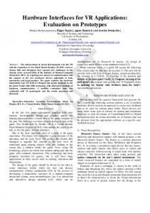
Buxton and Myers found out that executing compound tasks can lead to an increase of performance. However, it can also lead to a lag of performance. Therefore, it is necessary to analyze the impact of task switching for hands on the human brain. Figure 2.1 shows that when carrying out sequential tasks with one hand the brain has to switch between the tasks for the hand (top image). Even if tasks are carried out sequentially with two hands, an increase in speed can be gained if each task is applied to a certain hand as the brain does not need the switching time. This can e.g. be illustrated by pressing the keys Ctrl and s with the left hand instead of moving the mouse to the save button with the right hand while actually writing a text with the keyboard (bottom image).
Figure 2.1.: Carrying out tasks sequentially with one and two hands. Source: [Bux08b]
Basically, if tasks are found that can be carried out simultaneously (see figure 2.2), increases in speed can be made as well: if the tasks are appropriate for two hands they can be carried out simultaneously without any switching time (top). However, if the tasks are inapt for a simultaneous two-handed input, it can make things worse: then, the tasks are being carried out sequentially with a fairly large switching time (bottom). Buxton and Myers have shown that users can carry out compound tasks consisting of simple continuous actions without problems. Thus, two-handed compound tasks composed of simple discrete tasks should not overstrain a user. However, the cooperation of a user’s two hands
10
Figure 2.2.: Carrying out tasks simultaneously with two hands. Source: [Bux08b] goes beyond simple compound tasks. These principles should be explained in the subsequent section 2.2.
Kinematic Chain
According to Buxton, a human being’s two arms form a kinematic chain (KC) building a complementary organ. Amongst others, Buxton’s KC theory implies that both hands cooperate when interacting with the environment. The movements of the dominant hand (DH) are generally finer than those of the non-dominant hand (NDH). Thus, the NDH serves as a fixation hand: it assists the DH [Bux08b]. Take figure 2.3 for example: on the left side there is a sheet of paper with handwriting. On the right side there is a carbon copy that lay underneath the sheet when it was written. It can be perceived that the DH only operated within a small area. After each line the NDH adjusted the paper in a way that the DH could start writing on the same position on the new line where it started writing the line before. In real life interactions the NDH is moved only every few seconds while the DH does high frequency work of 5 to 7 movements a second (5 - 7 Hz). The KC theory provides a good foundation for two-handed interaction tasks: interaction in which the left hand acts as a fixture for the work of the right hand that does the precise work in a certain region on the screen should yield the best results for complex compound two-handed
11
Figure 2.3.: Two views of the same handwritten text. Source: [Bux08b] interaction tasks.
12
Chapter 3
Multi-touch Hardware
Touch interaction is usually provided by touch screens that can be used with one pen or finger. Single-touch hardware has been available since the early days of personal computing [BHR85]. Contrary to such single-touch hardware, touch screens that are multi-touch enabled can process several touch inputs simultaneously. Although Lee et al already introduced a multi-touch touch-sensitive tablet that was able to sense more than one finger in 1985 [LBS85], this technology has never been as successful as the single-touch analog. However, there has been an increase in popularity for multi-touch techniques recently. Firstly, Apple [App08d] has introduced the multi-touch capable mobile device iPhone [App08a] in 2006 that is explained in section 3.2.1. Secondly, Microsoft [Mic08c] has presented their multi-touch concept called Microsoft Surface [Mic08d]. Microsoft Surface is introduced in section 3.2.2. Thirdly, Jeff Han gave an impressing presentation [TED08a] at the TED conference [TED08b] in 2006 in which he displayed demos on a multi-touch screen, which technology is based on Han’s findings about the low-cost multi-touch sensing technique that is based on FTIR1 [Han05]. The technology FTIR is explained in section 3.1.1. Those multi-touch devices are based on different technologies. On one hand, there are capacitive systems that work with sensors that measure changes in capacity when they are touched or tapped. This technology will be explained in more detail in section 3.1.2. The iPhone (see section 3.2.1) or DiamondTouch [MER08a] (see section 3.2.4) are systems that are based on capacitive technology. On the other hand, there are systems that are based on CV2 i.e. touch impulses are being seen by a camera and processed by a computer. The Virttable (see chapter 4) has been built by employing CV technologies. Thus, multi-touch CV principles are described 1 2
Frustrated Total Internal Reflection Computer Vision
13
in detail in section 3.1.1.
3.1. Technological Foundations of Multi-touch 3.1.1. Computer Vision (CV)
Multi-touch technology that is based on CV (like Jeff Han’s multi-touch interaction wall [Han06]) employs one or more cameras to see how fingers are interacting with the touch surface.
Figure 3.1.: A multi-touch table that is based on the FTIR principle. Image by courtesy of Tim Roth [Rot08b]. Current CV multi-touch approaches usually work similar to the setup in figure 3.1: a video projector is connected to a computer and projects the image of an application onto a projection surface that is provided with a diffuser (e.g. a projection foil). In terms of a multi-touch table, the image could be deflected by a mirror to allow a light path from the projector to the diffuser that is long enough to produce an appropriately sized image. Contrary, for a multi-touch wall a mirror should not be necessary. The computer is also connected to a camera that is sensitive for
14
infrared light (e.g. a CMOS Firewire camera with a removed infrared light filter). The camera monitors the projection surface. On the computer a tracking software calculates touches out of the image that the camera captures by applying image processing techniques. The projection surface must be illuminated in order that a finger that is put onto the surface produces a light spot (a so called blob). This blob can be extracted with the tracking software on the computer. As the illumination must not interfere with the projection image, infrared light (IR) is used to light the projection surface: IR is invisible to the human eye but cameras can see it well (if the camera’s lens is not equipped with an IR filter). In this thesis four IR illumination models are explained: Frustrated Total Internal Reflection (FTIR) in section 3.1.1 (which is employed in figure 3.1), Diffuse Illumination (DI) in section 3.1.1, a combination of FTIR and DI called Diffused Surface Illumination (DSI) in section 3.1.1 and a method called Laser Light Plane illumination (LLP) in section 3.1.1. A serious downside of CV based multi-touch setups is lag. Lag affects the reaction time of the screen. This can be illustrated by a finger that is dragging a GUI element across the screen. Depending on the speed in which the finger is moving, the GUI element should always be lagging a bit behind. As this could be disturbing for the interaction with a multi-touch screen, the several components that lead to lag in a CV based multi-touch setup are discussed in section 3.1.1. Another problem of CV based multi-touch setups is that it usually needs to be dark in a room where such a setup stands in order that the camera can see a bright blob when a finger is pressed on the multi-touch screen. On one hand, the employed camera in a CV multi-touch setup can be equipped with a high-pass filter (e.g. an exposed negative of an analog camera can be placed between the camera’s sensor and the lens) that blocks out the visible light and thus makes only the IR light from the blobs visible to the camera’s sensor. On the other hand, ambient light like light from halogen lights, light bulbs or sun light contains high amounts of infrared light, which also passes the high-pass filter. This should be no problem if the tracking software can be configured in a way that it is still possible to highlight the blobs against the ambient light. The stronger and the more efficient the illumination technique of a CV based multi-touch table is the more ambient light can be in the room where the setup stands. However, the table is the
15
more sensitive, i.e. the less hard a finger has to be pressed on the surface to create a blob, the less ambient infrared light is in the room where the setup stands. Anyway, light sources like neon lights or energy saving light bulbs do not interfere with the tracking and only diminish the sensitivity of a CV based multi-touch setup a little bit. This means that the ideal location for such a setup is in a room with neon lighting and closed blinds.
FTIR: Frustrated Total Internal Reflection
Frustrated Total Internal Reflection as a means for the illumination of multi-touch tables has been introduced by Jefferson Han in [Han05]. According to Han, FTIR can be explained as follows: when light enters a boundary of a substance with a lower index of refraction like air or glass, it is refracted to a degree which is dependent on the angle of arrival. If the light enters the substance beyond a critical angle, it will undergo total internal reflection (TIR) i.e. it will be endlessly mirrored inside of the substance. This appearance is being employed to convey light abundantly with optical waveguides like fiber optics with very few fading of light. However, other mediums at the boundaries of this substance can frustrate this total internal reflection and initiate a light escape of the wave duct at the point of interference [Han05]. In terms of multi-touch, the wave duct substance could be a pane of glass or acrylic glass (see figure 3.2 and figure 3.1). Light from IR LEDs3 enters the glass from the sides. This light is endlessly internally reflected and is not emitted off the wide sides of the glass (or only with a small loss). If a finger touches the glass, it frustrates the internal reflection and causes the emission of light at the point where the finger touched the pane. The image in the top left of figure 3.2 shows the captured image of a camera in an FTIR setup while all fingertips of one hand are touching the acrylic glass. To build an FTIR multi-touch screen, a computer, a camera, a projector, a standard acrylic glass pane with polished edges, IR LEDs and a casing are needed. FTIR is very precise. Hence, touching acrylic glass or the diffuser with the bare finger does not frustrate the internal reflection strongly. Only the fingerprint is visible and thus only a small amount of the finger surface produces the emission of IR light. Therefore, an amplification of 3
Light Emitting Diodes
16
Figure 3.2.: Frustrated Total Internal Reflection (FTIR). Image by courtesy of Tim Roth [Rot08b]. the fingerprints is necessary: it is advisable to add a thin sheet of transparent silicone rubber between the diffuser and the acrylic glass pane (see figure 3.2). This sheet evens out the touch of the finger on the glass and should yield the highest possible reflection from a fingertip’s surface.
DI: Diffused Illumination
DI can be used in two methods: rear and front DI. Rear DI (as seen in figure 3.3) illuminates the screen from underneath with IR light. For this purpose LED floodlights can be employed, which are typically used for CCTV4 purposes. To achieve a well-lit screen, the emitted light from the floodlights needs to be evenly distributed in the setup. Additionally, DI also illuminates the space above the screen. In order that the tracking software does not see whole hands instead of proper blobs, it needs to be properly adjusted. Additionally to fingers, objects that are fitted with marker images on the bottom (so called props) can be used as input devices on the table if the tracking software supports the recognition 4
Closed Circuit Television
17
of markers.
Figure 3.3.: (Rear) Diffused Illumination (DI). Image by courtesy of Tim Roth [Rot08b].
Front DI places the LED lighting above the screen and causes the fingertips to appear darker than the rest. Thus, the tracking software needs to track dark instead of bright blobs.
DSI: Diffused Side Illumination
DSI is a mixture of both FTIR and DI. Basically, the setup is the same as with FTIR. The only difference is that instead of a regular acrylic glass pane with polished edges a special plastic glass pane with polished edges called PLEXIGLAS EndLighten [Evo08] is employed. The wide sides of an EndLighten glass pane are perfectly transparent like those from a regular acrylic glass pane. However, small particles within the glass cause light that is irradiated into the glass pane from the sides not to be totally internally reflected but emitted to the wide sides of the glass (see figure 3.4). The actual image that this illumination technique produces can be seen in the top left corner
18
Figure 3.4.: Diffused Side Illumination (DSI). Image by courtesy of Tim Roth [Rot08b]. of figure 3.4. Basically, the result is the same as with DI: the whole hand is illuminated and the tracking software must be precisely adjusted. Like DI, DSI supports the usage of props on the multi-touch screen.
LLP: Laser Light Plane illumination
Contrary to the other IR light approaches, LLP does not use LEDs as light sources but small IR lasers. The lasers power is in the low mW area (e.g. 10mW) [Gro08d]. The light of lasers is emitted in a narrow, low-divergence beam and is constrained to a narrow wavelength spectrum. But with the help of lenses the laser beam can be dispersed into a plane. This effect is employed in the LLP approach: the wavelength spectrum of the employed lasers is constrained to an IR wavelength (e.g. 850 nm) and through lenses the lasers’ light is dispersed into a plane that lies a little bit above the acrylic glass. If a finger enters the laser light plane the fingertips will reflect the IR light of the laser plane
19
Figure 3.5.: Laser light principle (LLP). Image by courtesy of Tim Roth [Rot08b].
and thus produce blobs. As the finger does not need to physically touch the tabletop, the table is ultra sensitive. Objects on the table can be dragged around with the slightest touch. However, if a fingertip enters the plane of a laser it can occlude other fingers from the laser light plane. Those occluded fingers would not produce blobs. The more laser modules are being employed in an LLP setup (e.g. four in all corners of a rectangular shaped table) the more unlikely the possibility gets that fingers can be occluded. Besides, laser light can have a high energy and thus be dangerous to the eyes. Especially infrared laser light can harm the eye but cannot be seen. Hence, security measures like wearing safety goggles must be met when working with LLP. Also, in the finished setup there must be no possibility for users to deflect the laser light into their eyes.
Comparison of FTIR, DI and DSI
A benefit of FTIR is that the light can be dispersed more easily than with DI and the light yield is better than with DSI. However, it is not possible to use props on the table. DI allows to use props on the table but it is rather difficult to achieve a balanced distribution of IR light. Additionally, reflections from the IR floodlight on the bottom of the acrylic glass pane irritate the camera tracking. This means that the dispersal of light needs to be carefully
20
planned with this technique. FTIR
DI
DSI
LLP
Light source
IR LED
IR LED
IR LED
IR Laser
Light yield
++
-
o
++
Silicone necessary
yes
no
no
no
Simplicity
o
+
o
++
Props possible
no
yes
yes
no
Price
++
o
+
-
Light difficult to
Special glass nec-
Danger for the
disperse; front &
essary, difficult to
eyes;
rear illum. poss.
obtain
occlusion
Miscellaneous
finger
Table 3.1.: Comparison of different multi-touch illumination techniques DSI has the advantage over DI that IR light can be dispersed as evenly as with FTIR. However, caused by the particles in the PLEXIGLAS EndLighten pane the light yield is inferior to FTIR resulting in a worse contrast between blobs and environment. On the other hand, props can be used with this setup. Another issue is that PLEXIGLAS EndLighten is softer than standard acrylic glass and can be scratched more easily during the setup process. Additionally, PLEXIGLAS EndLighten is more expensive than regular acrylic glass and more difficult to obtain pre-cut with polished edges. LLP has the advantage that the laser modules are easy to mount and should not be too expensive. Additionally, it should be better to use more than two lasers with LLP to prevent occlusion of fingers ([Gro08d]). A peculiarity of LLP is the danger of the IR laser to the human eye for which security measures must be undertaken. Table 3.1 summarizes the introduced multi-touch illumination techniques. For more information refer to [Gro08c]. Lag
Lag is a combination of delays that appear when employing a CV based multi-touch setup.
21
Those delays are caused by different factors: • Projector Lag: the projector that is used for a rear-projection screen needs a certain time to construct the image that it receives from the computer. At least this delay is as big as the frame rate: If the frame rate of the projector is 60 Hz, then the delay produced by the projector will be at least 1/60 s = 17 ms. Additionally, if the projector uses an LCD chip this chip will need some time to switch to the current image on the LCD chip. Thus, the projector’s bit of the lag should be around 17 ms + x. • Camera Lag: the camera of the setup is running with a certain frame rate as well, which depends on the camera’s hardware capabilities. Usually, a camera should support up to 60 Hz. However, some cameras only support up to 15 Hz. Additionally, the tracking system and the underlying computer should be able to run the tracking software as fast as the camera’s frame rate. Otherwise, the tracking frame rate can only be as high as the computer’s capabilities. With a frame rate of 60 Hz the camera produces at least a lag of 17 ms , with 15 Hz 67 ms. Additionally, the camera needs some time to transport the captured image to the computer’s main memory and the tracking software needs some time to read out this value. This bit of the lag heavily depends on the employed camera driver. To minimize this bit of the lag (which appears to be the real bottleneck) it is crucial that the camera has a fast driver and that the tracking software supports this driver. • Application Lag: this lag is a sum of certain application lags: the tracking software needs to process the image from the camera by applying certain CV filters and afterwards to recognize the finger coordinates. These coordinates are then dispatched to connected multi-touch applications. These must calculate the received coordinates into their domain and finally produce the output image that is sent via the graphics card to the projector. However, it is also a matter how the coordinates are being sent from the tracking software to the multi-touch application. In terms of a loose coupling of software components, this could be achieved as well via network.
22
• Network Lag: if the touch coordinates are being sent via network from the tracking software to the multi-touch application, this will take some time as well. Hence lag can be seen as
L = F rp + Lp + max(F rc , F rt ) + Ld + Lt + Ln + Lm
(3.1)
where L is the lag, F rp is the projector’s frame rate, Lp is the switching time of the projector’s LCD chip, F rc is the camera’s frame rate, F rT is the frame rate of the tracking application, Ld is the time that it takes after capturing the image with the camera until the tracking app starts to process the image, Lt is the time the tracking application needs to extract finger coordinates out of the camera image, Ln is the time that it takes to dispatch the coordinates to the multitouch application and Lm is the time that the multi-touch application needs to compute the output image.
3.1.2. Capacitive Touch Sensing
Basically, there are two systems for electronic touch sensing: the resistive and the capacitive system. In this section the capacitive system will be explained as existing multi-touch devices like the iPhone employ this system. To sense finger touches with the capacitive system in a single touch environment, a capacitive coating is placed under the surface of a screen. While operating, a charge is stored in this coating. When the screen is being touched, a bit of the charge is conducted to the user. Thus, the charge diminishes on the capacitive coating. Circuits in the corner of the screen quantify the amount of the diminished capacity and pass this information to the processor of the screen. This processor computes the position of the finger on the screen by interpolating between the different capacitive charge values in the corners of the screen. Employing the electrical phenomenon that a human finger leads electricity makes it impossible to use standard plastic pens to interact with a capacitive touch screen. In terms of light yield, the capacitive coating of an average touch screen conveys about 90 percent of the light from the screen [How08c]. On the desktop/notebook level, a research project like ThinSight aims to enhance custom shaped displays with capacitive multi-touch capabilities by mounting an additional board fitted
23
with capacitive electrodes behind a TFT screen [IHB+ 07]. A capacitive multi-touch hardware called N-Trig [NT08a] is about to go into batch production with Intel’s UrbanMax Mobile Computer platform [NT08b]. N-Trig enhances the multi-touch functionality with a support for pen interaction on the same hardware. The iPhone [App08a] adopts a capacitive multi-touch approach on the mobile device level and enhances it with different concepts that will be explained in section 3.2.1. Multi-touch hardware like the DiamondTouch table or the surface system SmartSkin [Rek02] offer a capacitive approach for front-projected multi-touch tabletop systems. As the DiamondTouch table offers more features as compared to the SmartSkin system, DiamondTouch is presented in detail in section 3.2.4.
3.2. Existing Products 3.2.1. iPhone
The iPhone3G (in the following called iPhone) [App08a] and the iPod Touch [App08c] are mobile devices manufactured by the company Apple [App08d]. iPhone and iPod Touch are very similar. As compared to the iPhone, the iPod Touch is lacking the phone functionality and the GPS receiver. Hence, only the iPhone should be explained throughout this section. The iPhone is a smart phone, which offers amongst others phone functionality, a music player, wireless Internet browsing, mobile mail and camera functionality. The iPhone is 115.5 mm tall and 62.1 mm wide [App08b]. In terms of interaction the iPhone features a multi-touch enabled touch screen.
Figure 3.6.: The Apple iPhone3G. Source: [App08f]
24
The iPhone seems to be a success for Apple: according to Apple’s announcement, over 1,000,000 iPhone3G were sold on the first weekend after its release [App08e]. This means that millions of persons use the iPhone. Hence, the iPhone sets the state of the art how interaction with (multi-)touch devices should be realized. A clear analysis of the iPhone’s touch functionality is necessary in order to adopt pieces of touch interaction design from the iPhone to other multi-touch products.
The iPhone’s Screen Technically
The iPhone’s screen has a 3.5 inch (8.89 cm) screen with a resolution of 480 by 320 pixels (this makes 163 ppi) [App08b]. The iPhone supports the tracking of multiple fingers on the screen.
Figure 3.7.: Self capacitance in the iPhone. Source: [How08a]
From Apple no information could be found regarding what kind of capacitor system they use for the touch sensing technology of the iPhone. However, Apple filed the patent #20060097991 on 11. May 2006, which describes a multi-touch screen that is based on self capacitance [Wal08]. As it is reasonable that Apple uses this technology for the iPhone, self capacitance should be explained in the following.
25
According to [How08d], the iPhone features a layer of capacitive material like other touchscreen monitors. In figure 3.7 you can see that differently to common capacitive systems transparent capacitors in the iPhone are adjusted in a layer according to a grid system under a protective glass pane. Its circuit can measure changes of charge on every node in the grid. Hence, every node of the grid can sense a touch and send this information to the iPhone’s processor. By employing this technique the iPhone is capable to track simultaneous touches in different areas of the screen.
Figure 3.8.: Touch calculation in the iPhone. Source: [How08b]
When a finger touches the screen of the iPhone charge of more than one capacitor in the screen drops. The iPhone’s processor takes all available capacitor information and calculates the touch information out of it (see figure 3.8). This information is passed to the operating system of the iPhone and can then be used by applications on the iPhone. Use of (Multi-)Touch in the iPhone
Touch is the main way to interact with applications on the iPhone. In the following some examples are given where single touch is used in a meaningful way on the iPhone: • There is a virtual touch keyboard that tries to predict, which word the user tries to enter. • Scrolling of content can be achieved by sliding a finger up and down the display. If the
26
finger is lifted up from the display while content is being slided vertically, an inertia is applied to the content and the sliding motion is slowly fading out. • A picker GUI element that resembles a wheel can be spun with a moment of inertia. • Turning a page or flipping between photographs on the iPhone (see figure 3.9) means that the user needs to slide a page to the sides up to a certain threshold. If this threshold has been achieved and the user releases the finger, the application will flip automatically to the next page or photo etc.
Figure 3.9.: Turning a page on the iPhone.
The main way to work with the iPhone is that one hand holds the device and the other hand operates on the screen. In this scenario only one hand can perform multi-touch operations. The operations that are given in the following are implemented on the iPhone as gestures:
• A pinching gesture is used to zoom on the iPhone. To use this gesture two fingers are put on the display of the iPhone and then moved away from each other (zoom in) or towards each other (zoom out). This gesture is e.g. used in the built-in Photos application of the iPhone (see figure 3.10 where the finger touches are displayed as grey circles).
27
• A rotate gesture can be applied by putting two fingers on the display of the iPhone and moving these fingers around a virtual circle. This gesture is not used by a built-in application on the iPhone.
Figure 3.10.: Zooming on the iPhone.
Actually, the only real multi-touch action that is currently used by built-in iPhone applications is the pinching gesture for zooming purposes. It is likely that Apple dispensed from more multi-touch interaction because it seemed too complex. However other multi-touch interaction techniques are technically possible. Those multi-touch techniques could include those that have been introduced in chapter 2: • For collaboration purposes (see section 2.1.3) the screen of the iPhone seems to be too small. • Two-handed interaction (see 2.2) could be achieved by placing the device on a table and two hands could be used on the device. Additionally, the iPhone could be held on the sides and two thumbs could be used for interaction on the sides of the screen. However, the usage of two hands on such a small screen can occlude large areas of the screen. To draw a conclusion for other (multi-)touch projects:
28
• Not everything needs to be multi-touch when interacting when multi-touch technology is at hand. • Adopt interaction metaphors from the iPhone e.g. apply inertia to objects, use the pinching gesture etc.
3.2.2. Microsoft Surface
Microsoft Surface is a research project from the Microsoft Hardware and Microsoft Research laboratories that started in 2001 [Mic08b]. After working out the concept of a prototype called T1 on a modified IKEA table in 2003 (see figure 3.11 on the left) the project finally proceeded to a similar shaped design (see figure 3.11 on the right).
Figure 3.11.: Left: Surface prototype T1. Right: Microsoft Surface table. Source: [Mic08b]
According to Microsoft, Surface “is the first commercially-available surface computing platform from Microsoft. …Today, it’s a 30-inch diagonal display in a table-like form factor that’s easy for individuals or multiple people to interact with.” [Mic08e]. It supports the following aspects ([Mic08e]): • Touch Interaction: users can grasp information with their hands. • Multi-touch Interaction: users can use more than one finger for interaction purposes.
29
• Multi-user: a Surface table can be used as a platform for co-located collaboration. • Object Recognition: specially tagged physical objects can be placed on the table in order to interact with the Surface table (see section 3.2.2). Additionally, Microsoft emphasizes the combination of operating system functions with touch and object interaction. E.g. the application Photo for Surface can dynamically download photo content from a digital camera via Wi-Fi and display these photographs on the table. In terms on how Surface hardware can be bought, Microsoft Surface’s FAQ page gives the information that Surface is not available for individual consumer purchase. Instead, Surface is being marketed for large-scale companies like Rio Hotels & Casinos and T Mobile in the United States that introduce Surface in public space [Mic08e]. Additionally, the information is given that Surface might be available for consumers in around three to five years [Mic08e].
Applications for Microsoft Surface
Amongst others, the following applications have been implemented for Surface [Use08] (see also figure 3.12): • Photos can e.g. download photos from a camera, spill them on the table. It allows interaction with those photos and by dragging a photo on a (specially equipped) mobile phone that is placed on the table the photo can be copied to this cellphone. Additionally, Photos enables the user to order photos as prints over the Internet. • Cell Phone: mobile phones that are tagged with a certain RFID
5
tag or a certain
fiducial marker can be placed on the screen and be recognized by Surface ([OW08]). Dedicated information of the mobile phone can be displayed on the table and functions like buying and downloading ring tones can be established directly on the table. • Restaurant is an application for restaurants that allows browsing of the menu and ordering of food directly from the table. 5
30
Radio Frequency Identification
• Mapping allows a user to browse events, show them on a map and store the locations in the user’s itineraries. Additionally, in Mapping a credit card can be placed on the table and tickets can be bought with this credit card. • Paint is a digital painting application. Surface Technically
Technically, “Surface uses cameras to sense objects, hand gestures and touch. This user input is then processed and displayed on the surface using rear projection” ([Mic08e]). The underside of the table is lit with infrared light. Thus, the Microsoft Surface illumination technique resembles diffuse illumination (see section 3.1.1). Touches and objects on the table are captured by infrared sensitive cameras and passed to an image processing system. This system computes the interaction information out of the camera’s images and passes this information to applications on the computer. The computer runs with standard hardware components under Windows Vista.
Figure 3.12.: Apps for Microsoft Surface. Source: [Use08] Additionally, the Surface table uses a technique called SurfaceFusion, which employs a com-
31
bination of RFID with CV for the tracking of objects on the table. SurfaceFusion is explained in more detail in[OW08].
Conclusion Microsoft Surface
Mainly, Surface is a research project of Microsoft. It seems like Surface has not been developed far enough to be manufactured in bulk production and sold to consumers. However, some large-scale customers show it in public space and thus promote it for Microsoft. Technically, Surface is fairly common (DI as illumination technique) but additionally it bears good ideas like the integration of RFID for tangible interaction. The application ideas are obvious but the integration of multi-touch, tangible interfaces and a close coupling to the OS seems promising for future innovations on tabletop interaction.
Figure 3.13.: On the left: the reactable in use. Source: [rea08a]. On the right: reacTIVision fiducials. Source: [rea08c]
3.2.3. reactable
The reactable is a tabletop tangible music instrument with multi-touch GUI elements [JKGA06]. Objects can be placed on the reactable as music control elements e.g. as a sound generator that produces a square wave. Regarding this example, the frequency of the square wave can be controlled by rotating the object and the amplitude of the sound can be controlled by sliding the finger around the object directly on the tabletop. Thus, reactable is a mixture of a tangible
32
and a (multi-)touch interface (see figure 3.13), which is a new combination for tangible and for multi-touch interfaces. In reactable objects can be used for a lot more musical functions, but this goes beyond the scope of this thesis. For more information about the reactable refer to [rea08d] and for a demo of reactable see [rea08b].
Figure 3.14.: reactable components. Source: [JKGA06]
reactable Technically
Technically the reactable is based on DI (see section 3.1.1). The image of the screen is rearprojected (see figure 3.14). Objects can be tracked because so called fiducials [BKa05] are mounted on them. These fiducials look similar to amoebas (see figure 3.13 on the right). reactable is based on an Open Source software called reacTIVision [rea08e], which tracks fiducials and fingers. reacTIVision passes the tracked information to an audio synthesizer and to an application that computes the graphics.
33
Conclusion reactable
In some aspects the reactable stands out: firstly, the reactable successfully combines multi-touch and tangible interaction. This is possible because the software reacTIVision can track fiducials and fingers simultaneously. Secondly, the reactable is a successful example on how co-located collaboration via tangible resp. touch interaction can be achieved because several people can play the reactable at the same time (see figure 3.13 on the left). Thirdly, the reactable is a music instrument (like in this case a synthesizer/sequencer etc.). Lots of music instruments like guitars, violins, pianos etc. are examples for human interaction with both hands. In this case a synthesizer/sequencer is used. Psychologically, in reactable continuous functions like Buxton explained them (see section 2.2) can be applied to each hand by controlling e.g. a sound generator with one hand and a Low Frequency Oscillator (LFO) with the other hand simultaneously. Additionally, the successful visual design of the reactable is contributing to the reactable venture. Thus, the reactable is an example for an ambitious concept and a sophisticated implementation of a multi-touch interface and should be taken into consideration when designing multitouch interfaces.
3.2.4. DiamondTouch
DiamondTouch is a research project of the MERL6 [MER08a]. It has been developed as an instrument for co-located collaboration via multi-touch in the early 2000s. The technical concept and application development possibilities are reflected in this section. DiamondTouch describes a multi-user touch technology to be used as an interactive frontprojected tabletop screen. It offers a touch-surface that can be used by different persons at the same time. Additionally, DiamondTouch is not affected by objects that are placed on it. The technological foundation of DiamondTouch enables the computer to discriminate which person is touching where on the screen [DL01]. 6
Mitsubishi Electric Research Laboratories
34
Figure 3.15.: DiamondTouch table in use and schematically. Source: [DL01]
DiamondTouch Technically
Technically, DiamondTouch describes a setup that employs capacitive coupling of a person and a table: under the tabletop a network of antennas is mounted. Each antenna uses another signal that is conducted via the body of a person that is touching the table and the signal is received by the chair on which the person is sitting (see figure 3.15). The receiver can discriminate the signals of the different antennas, which a person touches and thus interpolate the exact touch position (similar to the iPhone in figure 3.8). As each person is sitting on another chair, each touch can be mapped to a distinct person (if the persons are not touching each other). Objects that are placed on the table do not convey signals of the antenna to the chair and thus they do not interfere with the tracking. However, it is possible to create objects that can interact with the table. Hence, it is also possible to create tangible interfaces with the DiamondTouch technology. The image on a DiamondTouch table is front-projected by a projector that is mounted above the table (see figure 3.15 on the right). According to [DL01] DiamondTouch is a robust technique: firstly, it is not necessary to frequently recalibrate the table. Secondly, as the network of antennas is mounted underneath a tabletop, it is unlikely that these antennas are damaged in normal use. Thirdly, no stylus etc.
35
is necessary that could be lost. More information about the hardware of DiamondTouch can be found in [MER08a]. DiamondTouch Application Development
The MERL offers an SDK for DiamondTouch that consists of an ANSI C library, a Java [Mic08h] interface layer, a simple multi-user application example and a Windows application that provides mouse emulation, projector calibration and various diagnostic displays [EFRS02]. Additionally, the MERL offers an Adobe Flash [Ado08g] framework called DTFlash for DiamondTouch prototyping purposes [EW05]. More information about DiamondTouch applications and the DiamondTouch SDK can be found in [MER08b]. Conclusion DiamondTouch
DiamondTouch has the advantage over optical systems as described in section 3.1.1 that it is not depending on light sensitivity and electrical finger tracking via antennas and receivers should be fairly fast. Thus, objects being moved on the table should not be lagging behind the finger. However, as can be seen e.g. in the video in [MER08c], even DiamondTouch has a recognizable lag. DiamondTouch offers the discrimination between touching persons, which has not been possible with optical systems so far. A fundamental difference to the systems described in section 3.1.1 may be that DiamondTouch is used as a front-projection screen. There are positive and negative aspects to that: positively, that hands placed on the screen will reflect the image that is positioned underneath them if the projector is mounted at a 90 degree angle above the table. Hence, hands touching the screen cause less occlusion in a DiamondTouch setup than in a rear-projection setup. Negatively, as it is more difficult to create a compact or even mobile setup. The necessary receivers incorporated by chairs or armchairs contribute to this complex setup. Thus, a room with a fixed setup should be necessary.
36
Chapter 4
Building the Virttable
In this chapter the building process of the multi-touch table the Virttable (Versatile Illumination Research Touch Table) should be explained that has been built for this thesis. Although it is possible to develop multi-touch software with freely available multi-touch simulators (see e.g. section 5.2.2) it is inevitable to have an available multi-touch device in order to be able to actually test multi-touch software. The multi-touch devices iPhone [App08a] or iPod Touch [App08c] could have been used but they offer too few screen space to use full-grown visualizations on them.
Figure 4.1.: The Virttable
Multi-touch solutions like a Microsoft Surface table or a Diamond Touch table are either not for sale (Microsoft Surface) or seem to be too expensive (Diamond Touch). Thus, the decision was met to build an own multi-touch setup. This setup should …
37
• …be low-priced. • …also support tangible interfaces in order to provide a basis for tangible interface related research work (see e.g. [Hua04]). • …support collaboration research. • …be handy. • …be easy to transport. • …be easy to stow away. • …look as professional as possible.
Figure 4.2.: The Virttable from the sides The decision was met that LCD screens would be too small and too complicated in terms of building a multi-touch setup on top of it. Thus, a projector should be used as the image source. To achieve a compact setup rear-projection has been employed instead of front-projection. In terms of collaboration research and to achieve a compact setup a table is a better choice than a wall or a console. Users can gather around the multi-touch tabletop and a table can be easily stowed away in a locker that is large enough. If manufactured appropriately a multitouch table does not need to be assembled before each use. At the best, only the table’s power plug needs to be plugged into a power socket to make the setup work.
38
In terms of the basic tracking technique, capacitive systems (see section 3.1.2) are reliable and finger-sensing is very quick. On the other hand building such a system seems to be quite complicated, it does not scale easily for larger areas and for the support of rear-projected setups transparent capacitors are necessary.
Figure 4.3.: Composition of the Virttable with and without the hatch and lid attached
Setups based on CV (see section 3.1.1 for more details) can be built easily and cheaply. As an FTIR setup (section 3.1.1) can be easily converted to a DSI setup (section 3.1.1) by exchanging the acrylic glass pane, the decision has been met to initially build an FTIR setup and acquire an additional PLEXIGLAS EndLighten [Evo08] glass pane, which is necessary to convert the setup to DSI. The FTIR system has one of the best light efficiencies of the CV multi-touch illumination techniques and a DSI setup supports tangible interfaces. Hence, the system should be easily transformable from a touchable tabletop with a good light performance (FTIR) to a touchable and tangible tabletop. Principally, the Virttable (see figure 4.1) resembles a setup like illustrated in figure 3.1. Section 4.1 illustrates the rear-projection setup that has been employed for the table. Section 4.2 explains how the lighting that is necessary for the finger-tracking via CV has been integrated
39
into the Virttable. Additionally, it illuminates how the necessary acrylic glass has to be prepared in order to yield the best results for FTIR. Section 4.3 explains, which camera has been used and how a general purpose computer can be integrated into the setup. Section 4.4 outlines how the casing of the Virttable has been build.
4.1. Projection 4.1.1. Employed Projector
The video projector that has been integrated into the table is the consumer projector Panasonic PT-AX200E [Pan08] (see figure 4.4) that costs about 1000e. A computer can be connected to the The PT-AX200E digitally via a HDMI to DVI cable or in an analog mode via a VGA cable. The projector has a native resolution of up to 1280 x 720 pixels and thus an aspect ratio of 16:9. Because of this the acrylic glass and the table has to support this aspect ratio. Contrast and light intensity of the projector are fairly good for this price range (Contrast 6000:1 and light intensity 2000 ANSI lumen [Pan08]).
Figure 4.4.: Panasonic video projector PT-AX200E. Source: [Pan08]
A ring on the projector’s lens allows to adjust the size of the projected image and another ring on the lens allows to adjust the focus of the projector’s lens. However, a minimal distance of the projector to the projection surface is demanded in order to be able to produce a focused image. It has been tested manually that the minimal distance to the projection surface is 60 cm
40
in order to still get a focused image. The easiest way to use the projector in the setup would be to mount it vertically. Vertically it could either be mounted with the lens facing to the ground. Then a mirror would be necessary to deflect the projector’s image onto the acrylic glass pane. Or the projector could be mounted with the lens facing up. Then no mirror would be necessary. However, as the projection surface must be at least 60 cm away from the projector’s lens, this would mean that the setup needs at least to be 90 cm high (60 cm + 30 cm depth of the projector). But there are two reasons that prevent the vertical mounting of the PT-AX200E: 1. The ventilation suctions the air from the rear and the sides of the projector, conducts it over the projector’s bulb and blows out the hot air on the front ventilation opening (see figure 4.4). If the projector is mounted vertically an accumulation of hot air could be produced and the projector’s bulb could break. 2. The lens of the PT-AX200E is zooming in and out automatically when it is mounted vertically (the zoom ring is too loose and cannot be locked). Hence, the projector must be mounted horizontally and the projected image must be diverted by a mirror onto the screen.
4.1.2. Mirror Front-coated Mirror
On the left side of figure 4.5 the principle of the projection’s deflection via a mirror is shown: the projection is deflected by around 45 degrees by a mirror onto a projection surface. In rear-projection setups front-coated mirrors should be used. Common mirrors are glass panes equipped with a mirror foil on the back of the pane. This means that those mirrors are resistant against scratches. However, if they deflect images they will produce a phantom image. This originates from the soft mirroring of the glass pane’s front. This effect is illustrated in figure 4.5 on the right side: the rays sent by the projector are deflected twice, the first time there is a soft mirroring by the glass pane’s front and the second time the mirror foil itself deflects the rays
41
Figure 4.5.: On the left: using a front coated mirror to deflect a projected image. On the right: phantom image caused by a standard mirror. onto the backside of the glass pane. This would not be a problem if the angles of the deflected rays would not slightly differ caused by the small gap between the front and the back of the glass pane. Mirror Fixture
The adjustment of the deflection mirror is a tedious task: the mirror can be rotated around two axes and it must be adjusted to the appropriate x, y and z positions. Additionally, the projector’s position can be adjusted and rotated around the x, y and z dimensions and the image can be modified by adjusting the projector’s zoom and focus. However, with exact data from the projector (aperture, minimal screen distance etc.) exact calculation can be undertaken. Anyway, to realize the results of this calculation very precise cabinetmaker’s capabilities would be required to mount the projector and the mirror in the exact angle.
Figure 4.6.: CAD drawing of the mirror fixture. Image by courtesy of Wolfgang Baier [Bai08].
42
As this procedure was too exhausting for the scope of this thesis, the decision was met to build an all-purpose mirror fixture that can be easily rotated around two angles and adjusted around the x and y axes. Figure 4.6 shows a CAD rendering of the mirror fixture. The mirror is mounted in a U made of wood. The mirror can be slided up and down and be rotated in the U. Additionally, the U can be rotated around the screw that holds the U in place in the multi-touch table’s body.
Figure 4.7.: The finished mirror fixture
Figure 4.7 shows the fixture (without the mirror). The difference between the CAD drawing and the built fixture lies within the longer millings on the side of the U and the milling on the bottom of the U. This provides that the mirror has a larger range in the y direction and can additionally be adjusted in the x direction.
4.2. LED Wiring and Acrylic Glass The Virttable features the support of the FTIR and the DSI principle by making it possible to change a standard acrylic glass pane with polished sides (FTIR) to a PLEXIGLAS EndLighten XL [Evo08] pane with polished sides (DSI). Both principles demand that IR light is emitted into the respective pane from the sides (compare figures 3.2 and 3.4).
43
4.2.1. LED Wiring
According to Tim Roth [Rot08a], it is advisable to use IR LEDs of the type Osram SFH 485P, which should be a good choice for DSI as they feature a high light emission angle that leads to a good distribution of light in the EndLighten panes. FTIR will be supported as well if LEDs of this kind are employed.
Figure 4.8.: LED bars of the Virttable
96 LEDs of the type Osram SFH 485P (see figure 4.9, Image 1) have been integrated into the Virttable by mounting them into four aluminum bars that are located sideways of the glass pane (see figure 4.8). In the bars each LED has a distance of 2 cm to the next LED. Each LED is fixed in the aluminum bar with a plastic mount ring (see figure 4.9 Image 2). The LEDs are soldered together in arrays of 8 LEDs (see figure 4.9 Image 3) and a 0.25 W resistor with one ohm is soldered to the end of each array. The 12 arrays are then connected parallel to a 12V power supply unit. The distance between the LEDs and the glass pane should be around 3 cm in order to enable light dispersion. However, in FTIR, light that enters the border of the glass directly at the LEDs, is directly emitted through the glass pane at the boundary. This can e.g. be seen in the image from camera in figure 3.2: the white boundaries in this image show where the light from the LEDs is too strong and thus is emitted directly through the glass pane. At those boundaries a tracking of fingers is not possible because no contrast between finger touches and light can be established.
44
Figure 4.9.: 1. SFH 4855 LED, 2. LED mount ring, 3. LED circuit 4.2.2. Acrylic Glass
Two panes of acrylic glass are necessary for the Virttable: a standard acrylic glass pane with polished borders with dimensions of 560 mm * 360 mm, 10 mm thick and a pane of PLEXIGLAS EndLighten XL with polished borders with a dimension of 560 mm * 360 mm, 8 mm thick (actually 10 mm would have been better but that thickness has been not available pre-cut). For the projection a diffusion foil must be applied to the panes. For the panes of the Virttable a foil of the type Gerriets OPTITRANS [Ger08] has been used. The foil can be fixed with adhesive tape on the top or the bottom of the pane. However, in figure 3.2 it can be seen that the FTIR and the DSI pane of the Virttable are equipped on top with the diffusion foil, because when interacting with the screen and the foil is on top a user’s fingers are immediately touching the projection.
Using Silicone for Better Blobs
As already explained in section 3.1.1, a sheet of silicone on the acrylic glass for FTIR is necessary to physically amplify the finger touches on the glass pane. For this purpose the application of a thin sheet (around 0.5 mm) of a two-component silicone rubber called SORTA-Clear [SO08] between the acrylic glass and the diffuser is necessary. This can be achieved by sticking 5 lanes of adhesive tape (Scotch tape) on top of each other at each boundary of the acrylic glass pane, then pouring the liquid silicone that has a consistency like honey on the pane and
45
dispersing the silicone with an aluminum ruler on the pane.
Figure 4.10.: Cameras tested in the Virttable
4.3. Camera, Software and Computer As has been introduced in section 3.1.1, a camera and a computer are necessary in a CV based multi-touch setup. The camera monitors the acrylic glass for blobs and is connected to the computer. The computer is running an image processing software that extracts blobs from the camera image and dispatches this information to multi-touch applications. The camera(s) of the Virttable should be introduced in section 4.3.1 and the computer and the tracking software that are used in the Virttable should be illustrated in section 4.3.2
4.3.1. Camera
The camera employed for the Virttable is a Unibrain Fire-i Firewire camera [Uni08] with a Tamron 13VM308ASIR CS mount zoom lens [Tam08]. However, additional experiments have been conducted with a Point Grey Firefly MV Firewire (color version) camera [Gre08c]. In figure 4.10 the Fire-i can be seen on the left and the Firefly MV on the right. In an IR light environment it is important that the camera’s characteristic has a high sensitivity in the near-infrared spectrum. The more sensitive the better. On the left side of figure 4.11 the optical characteristic of the Point Grey Firefly MV can be seen: it has roughly the
46
same sensitivity for infrared light up to a wavelength of 850 nm as for light from the visible spectrum. (The black MONO line is not valid for the color version of the Firefly MV). A camera for blob tracking should feature a driver that supports image processing with a lag as small as possible. This means that the camera has to provide the captured image as fast as possible to the image processing application. This speed seems to depend highly on the quality of the employed camera driver. However, this information is not easily available about a camera. The choice for the tested two cameras has been made after intensive reading of the NUI group forums [gro08b], where other users, who built CV based multi-touch setups, share their experience.
Figure 4.11.: On the left: Optical wavelength characteristic of the Point Grey Firefly MV. Source: [Gre08a]. On the right: Optical wavelength characteristic of the Osram SFH 485P. Source: [Sem08]
Bandpass Filter
Usually, lenses hold a low-pass filter that filters out IR light. If this IR filter is removed images from a camera that is equipped with that lens will look much too bright because a camera chip sees IR light as white light. Contrary to this, a camera in a multi-touch setup should see as much IR light and as few
47
light of the visible wavelengths as possible. Therefore, the lens must not hold an IR filter. Instead a filter for light of lower wavelengths is necessary (a high-pass filter). The Tamron lens that is used in the Virttable’s setup has been ordered without an IR filter. To find a filter that filters out light of lower wavelengths is not complicated. An exposed negative of an analog camera can be placed in the camera’s CS mount socket between the camera and the lens. Such a negative can often be found within developed negatives (mostly at the start of the photo film). Then it is available for free. This solution provides a high-pass filter i.e. all light beginning with the near-infrared spectrum can pass the filter. However, with this high-pass filter the infrared light of the sun and of other light sources can pass the filter as well and worsen the contrast of the finger touches in contrast to the surrounding in the camera’s image. Not all light of the infrared spectrum is necessary: LEDs emit light in a very narrow spectrum. In the case of the SFH 485P the peak wavelength is 880 nm and the most light is emitted between 850 nm and 975 nm (see figure 4.11 on the right). For the Virttable that means the employed camera must see only light of that interval. As the sun and many other light sources e.g. light bulbs or halogen lights emit light in the infrared-spectrum, the light of those sources overlap with the light from the IR LEDs. However, there are artificial light sources like neon lights and energy-saving bulbs that produce nearly no infrared light and thus do not affect the multi-touch tracking. With an optical bandpass filter it is possible to let only light of a particular wavelength interval pass to the camera chip. In the case of the Virttable this bandpass should only admit light of an interval around 880 nm. For the Virttable an optical bandpass filter has been mounted on top of the Tamron lens: the bandpass FW880-40 from the company Thorlabs [Tho08] (see figure 4.12). Its admission wavelength is at 880 nm and it features an edge steepness of 40 nm. This means that light of a wavelength interval between 840 and 920 nm can pass the filter (the nearer to 880 nm the brighter). This filter costs around 100 e and should yield better results than a simple high-pass filter made from a photo negative. However, other infrared light sources also emit light in the same interval as the Osram LEDs
48
Figure 4.12.: Thorlabs bandpass that has been tested with cameras in the Virttable. (i.e. between 840 nm and 920 nm). As the Thorlabs bandpass filter also damps the light from the LEDs, the results with the bandpass were worse than the results with the low-cost negative film high-pass filter.
4.3.2. Tracking Software and Computer
Actually, the computer is not part of the Virttable. Each computer with an appropriate tracking software can easily be integrated into the Virttable. All that is necessary is a Firewire port for the camera and a socket for the display cable. However, for testing purposes a Mac Mini with 1.67 GHz and 2 GB RAM has been employed. The Mac Mini runs Windows XP with Service Pack 2 via Bootcamp (i.e. it runs Windows natively). The Touchlib [gro08f] has been employed as tracking software. Touch tracking and thus the Touchlib’s principles are explained in chapter 5.
4.4. Casing The casing of the Virttable is made out of MDF1 boards that are 16mm thick. It consists out of a casing body and a lid that can easily be removed from the table in order to exchange the 1
Medium Density Fiber
49
glass panes (and thus to change between FTIR and DSI). On the bottom of the body wheels are mounted.
4.4.1. Casing Body
The casing body consists of two parts that can be separated from each other: 1. The body itself 2. A hatch that is held in place by four magnets. It can be removed in order to grant access to the technical components of the table like the video projector or the camera. Vice versa it can easily be clipped back on the body (see figures 4.3 and 4.13).
Figure 4.13.: Virttable with and without hatch attached On top of the casing the LED bars are mounted (see figure 4.9). In the table itself switchable power sockets can be found into which the projector and the LED power supply unit are plugged in. The projector is held in place by three wooden boards. On the front, back and on one side of the body ventilation openings are provided (see figure 4.2). These are in line with the ventilation openings of the projector and assure the ventilation of the projector. An opening in the body provides access to the projector’s connectors without removing the hatch (see figure 4.14 on the right).
50
Following cable connection that are not permanently fixed are necessary for the Virttable’s operation: 1. Camera with computer 2. Computer with projector 3. Computer with power socket
Figure 4.14.: Openings in the Virttable’s body: cable channel (left), projector connections (right) The casing supports a computer that is placed outside of the table as well as a computer that is small enough (e.g. a Mac Mini) inside of the casing – both with a closed hatch. Therefore a cable opening has been integrated into the casing (see figure 4.14 on the left). The computer’s power cable can be plugged into the power sockets inside of the body.
4.4.2. Casing Lid
The lid is 46.5 cm wide and 66.5 cm long and made from a 5 mm thick MDF board that has a rectangular shaped 30 cm * 50 cm opening where the access to the acrylic glass is. Four bars are attached at the boundaries to hold the lid in place when it is mounted on top of the body. The paintwork of the lid is as white as the table but on the underside and at the boundaries of the rectangular shaped opening it is painted in matte black (see figure 4.15). If the underside were white the IR light emitted from the LEDs would be reflected by the lid and emitted through the glass from the top and thus disturb the tracking.
51
Figure 4.15.: Paintwork of the Virttable’s lid: white on top, black on the bottom.
4.5. Conclusion Building the Virttable The demands towards the Virttable’s hardware have been met: the Virttable is portable and supports multiple illumination techniques, which can still be easily enhanced. The Virttable’s body is solid, looks tidy and professional and allows easy access to all components. The rearprojection mirror can be easily adjusted but still be fixed when the appropriate bearing has been found. All the parts (except from the projector and the Mac Mini) sum up to less than 1000 e.
52
Chapter 5
Software Development for Multi-touch Hardware
The development of multi-touch enabled software is based on many aspects. On one hand there are many hardware related issues and the question how touch information is provided for the applications. On the other hand there are HCI-related aspects that should be considered when designing and implementing software that should be used via multi-touch interaction. Some important HCI issues have been introduced in chapter 2. Basically, the research work for this thesis has been carried out with the Virttable (see chapter 4). The Open Source software Touchlib [gro08f] has been employed as tracking software, which means that it is free and can be modified. The Touchlib is not a commercial software and is not completely stable. However, for the purpose of this thesis the Touchlib seemed to be the best choice because it is based on components that can be easily configured or exchanged. The Touchlib like some other Open Source multi-touch tracking applications e.g. reacTIVision [KB07] (see section 3.2.3) makes use of the TUIO network protocol as a means to convey touch events. By employing this protocol multi-touch software and tracking software can be decoupled from each other. In this chapter the configuration of the Touchlib and its CV components are explained in section 5.1. As TUIO has been used heavily as a means to connect finger tracking and multitouch applications throughout the work of this thesis, it is introduced in section 5.2. Finally, section 5.3 introduces some fundamental how-tos for multi-touch application development.
53
5.1. Configuration of Finger Tracking As has been explained in section 3.1.1, each finger on the screen is represented by a spot of infrared light called blob. Those blobs can be processed by the tracking software. Initially it is crucial to configure the CV setup in a way that it yields proper blobs for the tracking software. For finger tracking the software Touchlib [gro08f] has been employed. The Touchlib can be configured with the special configuration application configapp.exe in the Touchlib folder. This application is a graphical front end for the file config.xml in the Touchlib folder. The adjusted configurations of configapp.exe are saved to config.xml.
Figure 5.1.: Tasks of the software Touchlib.
As illustrated in 5.1, the Touchlib executes components in a chain. In the first step the tracking software captures a picture from a connected camera (task 1 in figure 5.1). The received image can then be processed and touches be recognized (task 2, 3, 4). Afterwards, the camera coordinates of the recognized blobs need to be transformed to screen coordinates (task 5). In the last step the touch information is sent to the connected multi-touch application (task 6) The components of the chain in figure 5.1 must be appropriately configured in order to work correctly.
54
5.1.1. Camera Configuration
Initially the capturing with the camera connected to the Touchlib should be configured. The camera Point Grey Firefly MV of the Virttable (see section 4.3.1) can be used with at least two video libraries with the Touchlib: • DSVL: the DirectShow Video Library [Sou08a] is a cross-platform Open Source video library that supports the Microsoft DirectShow system [Mic08a]. That means with DSVL all cameras can be included into applications that support the DirectShow standard. Camera drivers that are built on the Windows Driver Model (WDM) [Mic08f] should support DirectShow. The Point Grey Firefly MV offers a WDM driver called FlyStream [Gre08b]. • VW: VideoWrapper [Sou08b] is as well a cross-platform Open Source video library. It supports certain proprietary camera drivers amongst others the Point Grey Firefly MV proprietary camera driver that is based on FlyCapture [Gre08d]. This is particularly important because only VW supports the proprietary driver of the Firefly camera, which is remarkably faster than the WDM driver, which is as well provided by Point Grey. With VW and the FlyCapture driver the time between the image has been captured until it can be processed by the computer is remarkably shorter. Thus VW and the FlyCapture driver contribute less to the setup’s lag (see section 3.1.1). The choice for the video library can only be set manually with a text editor within config.xml by replacing the default first sibling element dsvlcapture of the filtergraph element to the following vwcapture element (see listing 5.1). 1
2
−−>
3
< v w c a p t u r e l a b e l =” c a p t u r e 1 ”> < v i d e o s t r i n g v a l u e =” p g r : 0 640 60 g r e y 8 1 r g b ” />
4
5 6
...
55
7
Listing 5.1: Configuring VW in config.xml.
Additionally, all DLLs from the Point Grey folder where the camera driver has been installed must be copied to the Touchlib folder. The FlyCapture driver can be configured with the program PGR FlyCap by Point Grey. The Firefly camera controls its properties like frame rate, shutter, gain, brightness and exposure automatically. Alternatively, those properties can be manually adjusted with PGR FlyCap. Throughout the research work it turned out that for the best light sensitivity it is crucial to regulate the exposure value of the camera manually and choose a small value. This is illustrated in figure 5.2: both images have been taken under the same, relatively bright daylight conditions. The only difference between both pictures relate to the exposure value. In the left image the value 58 was chosen automatically by the driver. In the right image the value was modified manually to 22.
Figure 5.2.: Changes in exposure value with PGR FlyCap.
56
As for the tracking software the contrast between blobs and environment should be as big as possible, it seems to be clear that for a sensitive setup in relatively bright conditions it is essential to adjust the exposure value to a small value. However, it depends on the strength and amount of the employed IR LEDs how low the exposure value can be set to still provide recognizable blobs in a bright environment. The more LEDs and the stronger they are the better. Within PGR FlyCap adjusted values can be saved to the Windows registry. VW does automatically adopt adjusted values.
5.1.2. Background Subtraction
The captured image from the camera is passed on to a background subtraction filter in the filter graph (see figure 5.1 task 2).
Figure 5.3.: Filter chain of the Touchlib
The filter backgroundremove subtracts a background image from the captured image. As can be seen in figure 5.3, that means to remove the environment around the blobs. The background image can be taken whenever the tracking software is started. As soon as lighting conditions change, the background image must be taken again. Efforts have been undertaken to integrate another background filter, which computes background images based on an adaptive background mixture model for real time tracking [KB01] (based on [Ziv04]). This background filter has been realized as Touchlib filter chain element. However, this filter has not worked
57
well as the implementation yielded bad background subtraction results and a poor performance (ca. 1.5 Hz). Anyway, a better background filter than the one built into the Touchlib should be feasible (e.g. based on the calculations from section 9.3.2).
5.1.3. Brightness and Contrast Adjustment
The brightnesscontrast filter (see figure 5.1 task 3) can be used to amplify the contrast between brighter and darker regions of the image that is conveyed from the background subtraction filter. Usually relatively high values e.g. 235 (of 255) for the brightness and 249 (of 255) for the contrast yield the best results (see figure 5.3).
5.1.4. Screen Calibration
It is necessary to calibrate the screen in order to determine the parts of the camera’s image that should be used by the tracking software i.e. only parts within a bounding box should be interpreted.
Figure 5.4.: Screen calibration view of the Touchlib
58
Additionally, each lens has some kind of distortion. The better the lens the smaller is the distortion. However, in terms of the low-cost setup of the Virttable a rather cheap Tamron zoom lens has been employed (see section 4.3) that has a rather strong distortion. Hence, the touch area of the screen in the camera’s image must be rectified. There are different approaches to achieve this with a computer. The way the Touchlib solves that problem is to declare 20 positions on the screen (the green crosses in figure 5.4), which have to be touched subsequently throughout a calibration process. After the calibration process the positions of these 20 points are written into the 20 child elements point of the element screen in config.xml. Blobs that are extracted from the captured image while the tracking process are checked whether they lie within the bounding box and if so it will be checked which are the four adjacent points of the twenty stored points of the blob. The final screen coordinate of the touch is then interpolated between the positions of the four adjacent calibration points. Touchlib yields coordinates between zero and one in x and y direction. The top left has the position 0,0 and the the lower right 1,1. That means multi-touch applications need to calculate the appropriate application coordinates out of these values. E.g. the value x = 0.7 and y = 0.5 on a screen with the resolution 1280 x 720 means that the pixel x = 896 and y = 360 has been touched.
5.1.5. Hot Spot Problem
In a rear-projection setup the image that appears on the screen is projected by a projector. This projector uses a light source that also emits IR light. Oddly enough, this IR light is especially strong on a certain spot of the acrylic glass. This spot is called hot spot. In figure 5.5 the hot spot can be seen: it appears as a white spot. However, this spot can be removed with the background subtraction. But certain aspects are connected to it: • If the hot spot is removed with the background subtraction the hot spot area will be blind for touch interaction as there is no contrast between touch and hot spot possible. • The hot spot gets the biggest with a bright background as a bright background reflects the most light. This means that a white background image is recommended when taking the
59
background subtraction image to maximize the hot spot. Otherwise the background of an executed multi-touch application could make the hot spot bigger than the one stored in the background image and thus be recognized as a blob. • If the screen is pressed rather hard the hot spot can outshine the previous hot spot area and thus be recognized as a blob. That cannot be overcome easily with the tracking software and must be somehow carried out by the multi-touch software e.g. by declaring a screen area in which interaction is ignored.
Figure 5.5.: Projector hot spot in a Touchlib configuration window. However, there are a few approaches how the hot spot could be overcome technically: • Instead of the front-coated standard mirror that has been employed in the setup a cold mirror could be used: this kind of mirror reflects only light of wavelengths of up to 700 nm and thus acts as an optical low-pass filter. For light with a higher wavelength a cold mirror is perfectly transparent. On the other hand a cold mirror of the size 11 cm x 18 cm costs around 450 e, which has been too much for the project’s budget. • The diffusion foil could be attached to the back of the acrylic glass: the foil scatters the light so much that the hot spot does not appear (or only weakly). Currently the underside of the acrylic glass is glossy. However, applying the foil to the back prevents the usability
60
of the Virttable with objects because patterns attached to objects cannot be recognized through the foil on the underside of the glass pane (the pattern is blurred by the distance between the foil and the pattern). However, pattern recognition works well with the foil on the top side of the pane. Another problem is the sheet of silicone on top of the acrylic glass. This sheet must be covered somehow. If the foil was attached to the underside a transparent foil could be attached to the top side. However, it is quite difficult to attach a transparent foil on the silicone without producing bubbles under the transparent foil and without harming the silicone sheet. • An infrared light filter could be put between the projector’s lens and the mirror. Indeed, that has been tried out with a cheap IR filter glass but that has not worked. Maybe a better filter could eliminate the hot spot.
5.2. Connect Finger Tracking with Applications: TUIO TUIO is an approach to supply a basic and multifunctional communication protocol between tangible tabletop controller interfaces and fundamental application layers [KBBC05]. TUIO is based on the Open Sound Control (OSC) protocol [Wri08], which is intended to provide a protocol to interconnect music synthesizers, computers and other multimedia devices over the network. With TUIO there is a message producer and a message receiver. TUIO messages are dispatched over the network via UDP datagrams. UDP is employed because it has a smaller network latency than TCP. Applications that want to receive TUIO datagrams can open up a socket on the IP of the message provider (usually on port 3333) and listen for TUIO messages. TUIO supports touch and object interaction whereas in the TUIO context it is only spoken about objects (thus a touch is a TUIO object as well). TUIO messages come in bundles of at least three TUIO messages: 1. set messages convey details about an object’s conditions like position, orientation and other states [KBBC05]. Whenever an object is moved a new set message will be dispatched containing state information. Each object e.g. a touch object gets a unique id
61
when it is being added to stage. This id stays the same for each object on the tabletop as long as this object stays on the table. 2. alive messages contain the current set of objects present on the surface using their ids. Those messages convey the information to connected applications about which objects are still on the table even if they are not being moved. 3. fseq messages add a unique id to each bundle of TUIO messages. There are no explicit add or remove messages in the TUIO protocol. That should help to overcome possible packet losses of the UDP protocol. This means that the receiver (e.g. a multitouch application) must perceive the adding and removal of TUIO objects on its own. E.g. the adding of an object can be recognized with a set message that contains an id that has not yet been used and the removal of an object can be identified by examining the alive messages. If an id of an object is missing in the alive message that necessarily means that the object has been removed from the table.
5.2.1. Message Format
Each TUIO bundle consists of the following layout and of at least three messages: 1
/ t u i o /[ profileName ] s e t o b j e c t I d [ s t a t e i n f o r m a t i o n to o b j e c t I d ]
2
/ t u i o /[ profileName ] a l i v e [ a c t i v e o b j e c t s I d s ]
3
/ t u i o /[ profileName ] f s e q i n t 3 2
Listing 5.2: TUIO bundle format The enumeration of all TUIO profileNames would be out of scope for this thesis but two of them are particularly interesting: • 2Dobj contains information about an object on the tabletop. • 2Dcur contains information about a cursor object on the tabletop e.g. a finger’s position. For this thesis TUIO has been employed to dispatch touch positions and thus mainly the 2Dcur profile name has been used.
62
5.2.2. Using the TUIO Simulator
Figure 5.6.: TUIO simulator.
It would be tedious to develop TUIO enabled applications only with a multi-touch setup because each time the application was changed it had to be copied to the computer of the multi-touch setup and debugging on the multi-touch screen would be uncomfortable. However, there is a TUIO Simulator application [rea08e] that has been programmed in Java [Mic08h] and thus works across platforms. A screenshot of the TUIO Simulator can be seen in figure 5.6. The white area simulates the interaction surface.The grey dots are touch interactions that have been fixed. That means those interactions are being sent constantly via TUIO messages to connected applications and thus simulate multi-touch interactions.The grey dots can be set by Shift-clicking somewhere in the interaction surface and can be moved around by dragging them with the mouse. A single-touch impulse can be given by simply clicking on the white background somewhere and dragging around the mouse on the interaction surface. The colored shapes that are dispersed around the interaction surface can be used to simulate object interaction.
63
5.2.3. Using TUIO with Adobe Flash
Adobe Flash Actionscript 3 (AS3) [Ado08b] has been used extensively for application development throughout this thesis. Hence, in this section it should be explained how TUIO can be used with the employed AS3. As AS3 lacks the support for UDP but supports socket connections via TCP, a workaround must be applied in order to make TUIO work with AS3. Figure 5.7 shows this workaround: a small application called FLOSC1 [Ben08] translates between UDP and TCP. The TUIO message producer (e.g. the Touchlib or the TUIO Simulator) sends its messages to FLOSC. FLOSC repacks the OSC UDP message into an XML format and dispatches it via TCP to the Flash (AS3) application that is connected to FLOSC.
Figure 5.7.: Using TUIO with Adobe flash. Source: [gro08g]
1
Flash OSC
64
5.3. Use of (Multi-)Touch in Applications As there has been a free Touchlib TUIO AS3 implementation, it has been used [Goo08]. In the following some aspects are being illustrated, which are important for the work with multi-touch and the TUIO AS3 implementation. TUIO AS3 listens on TUIO messages and manages a list of TUIO objects. If a message with a new touch object is being received the id and other information like the position will be stored in a global list. Furthermore, if the touch object is removed from the tabletop it will be removed from the global list as well by TUIO AS3. The global list with the TUIO objects can be accessed by other objects of the application. Flash applications are running with a certain frame rate e.g. 15 FPS2 . AS3 Objects can declare functions that will be triggered at the start of each frame by an enter frame event. Those enter frame functions allow to calculate frame based animations.
5.3.1. Differences Between Mouse and Touch Events
There are certain aspects of multi-touch events that discern them from mouse events. A mouse is used to perform clicks and a finger to perform taps. Depending on the implementation of the touch events there is no analog function to mouse over events. Either a finger is pressed on the screen or not. The finger is not always present on the screen like a mouse pointer. A mouse over event could e.g. be used to trigger tool tips. However, there could be a workaround for this problem e.g. if a finger stays longer than a second on the same spot it could trigger a tool tip. As fingers are not as precise in selection as mouse arrows, pixel accurate interaction is difficult with fingers. E.g. Microsoft recommends in their touch interaction guidelines [Mic08g] that touchable GUI elements should be at least 23x23 pixels or 13x13 DLU 3 large. 2 3
Frames Per Second Dialog Units
65
5.3.2. (Multi-)Touch Interaction Implementation Tap Down and Tap Up
On the other hand, to separate between click/tap actions and drag actions on the same object it is necessary for both technologies to check whether the mouse/tap down point is the same as the mouse/tap up point. If it is the same a click/tap has been performed. If not a dragging action has been performed and the click/tap action must be suppressed. However, a problem that frequently emerges when using taps instead of clicks is that the tap up point mostly differs slightly from the tap down point even if subjectively a tap has been performed because a finger is not as precise as a mouse pointer. Hence, it is necessary to check if the tap up has been performed within a certain surrounding: 1
v a r TAP_UP_DELTA : Number
= 5;
2
i f ( tapDownX >= e v e n t . x−TAP_UP_DELTA &&
3
tapDownX = e v e n t . y−TAP_UP_DELTA &&
5
tapDownY 1){
20 21
this .x = inertia .x;
22
i n e r t i a . x = i n e r t i a . x * FADE_OUT ; } else {
23
i n e r t i a . x = 0;
24
}
25
i f ( i n e r t i a . y > 1){
26 27
this .y = inertia .y;
28
i n e r t i a . y = i n e r t i a . y * FADE_OUT ; } else {
29
i n e r t i a . y = 0;
30
}
31
i f ( i n e r t i a . x == 0 && i n e r t i a . y == 0 ) {
32
r e m o v e E v e n t L i s t e n e r ( E v e n t . ENTER_FRAME,
33
handleDraggingWithInertia ) ;
34
}
35
}
36 37
}
Listing 5.7: Implementation of dragging with inertia Listing 5.7 enhances the code from listing 5.5 with a fade out motion of the containing object: in lines 9 to 13 the last two touch positions are stored. As soon as the touch is released from the table, the inertia is calculated as the delta from the last two touch positions (lines 16, 17). Afterwards, the code from the lines 20 to 31 is executed in every frame until the inertia is zero. For this purpose, in each frame the inertia is added to the current position in the x and in y direction. Additionally, the inertia is diminished in every frame by the factor FADE_OUT (with 0 < FADE_OUT < 1). By modifying FADE_OUT, the duration of the fade out can be
71
changed. As soon as the inertia in x or y direction is smaller than 1, it is set to 0 and the motion in the particular direction stops (lines 20, 26). When the inertia of both directions is 0, the enter frame function stops (lines 32 to 34). Although the introduced way to calculate the inertia is correct, it suffers from a few flaws: • The last two positions are sometimes the same as Touchlib could not deliver new positions in the same rate that Flash runs into a new frame and thus calls the function twice with the same values. In that case, the motion of the object will stop abruptly. • Sometimes the values delivered by the Touchlib are not in the same order as the movement of the finger has been. E.g. a movement of the finger from left to right could take place but the Touchlib could deliver the last two touch object positions in a way that it looks like a movement from right to left. In that case, the inertia will be applied against the actual motion direction. Thus, it seems to be better to store a set of the last positions and calculate the average speed as soon as the finger has been released from the tabletop: 1
// w h i l e d r a g g i n g t h e f i n g e r on t h e s u r f a c e :
2
lastPosInertia4 .x = lastPosInertia3 .x
3
lastPosInertia4 .y = lastPosInertia3 .y;
4
lastPosInertia3 .x = lastPosInertia2 .x
5
lastPosInertia3 .y = lastPosInertia2 .y;
6
lastPosInertia2 .x = lastPosInertia .x;
7
lastPosInertia2 .y = lastPosInertia .y;
8
lastPosInertia . x = tuioobj . x ;
9
lastPosInertia . y = tuioobj . y ;
10
/ / . . . and t h e n a s s o o n a s t h e f i n g e r i s
11
inertia .x =
lifted :
12
( lastPosInertia3 .x − lastPosInertia4 .x) +
13
( lastPosInertia2 .x − lastPosInertia3 .x) +
14
( lastPosInertia .x − lastPosInertia2 .x );
15
i n e r t i a . x = i n e r t i a . x / 3;
72
16
// a c c o r d i n g l y f o r t h e y d i r e c t i o n
Listing 5.8: Implementation of dragging with inertia with a set of values
73
74
Chapter 6
Requirement Analysis for the Test Application Vispol
6.1. Introduction Vispol (abbr. for “Visualization for the police”) is an application that is being developed in a collaboration of the Wiesbaden University of Applied Sciences with the police of the state of Hesse (Germany). Vispol should be used in the department for the coordination of special operations of the police of Hesse.
6.1.1. Context Analysis
By the time the work on Vispol has started in the scope of this thesis, another research group of the Wiesbaden University of Applied Sciences had worked on it. Thus, the context analysis for Vispol is based on two parts: on one hand, findings of the previous group have been incorporated. They analyzed the requirements for Vispol by visiting the special operation coordination facilities and conducting interviews with the persons in charge of the police’s special operation team. Additionally, two interviews have been conducted with responsible persons from the special operation team by the author of this thesis in the Wiesbaden University of Applied Sciences.
6.1.2. Background to Vispol
Whenever a special situation like a hostage-taking or bank hold-up is taking place in Hesse, the special operations control team gathers in a supervision room, which is fitted with technical equipment to supervise and coordinate this situation (see figure 6.1). From this room, all police operations of the police on-site of the situation are being scheduled. One part of the equipment
75
Figure 6.1.: The supervision room is equipped with technical appliances of the police of Hesse is a server software called ILIAS-He, which is a web application. It provides means to collect all information about a situation in a central location. A piece of information could be e.g. the name of a concerned person of the situation, which has been investigated by the police on-site. ILIAS-He is being controlled by policemen, who look after the data that is being entered into the system and who sieve out information that is especially important for the leaders of the staff. To collect data and to visualize the situation for the coordinators, pinboards and whiteboards are being employed. E.g. in figure 6.2 you can see how information is arranged by the means of note cards on a pin-board. Vispol focuses on a part of the police work in the special operations field. Usually, different persons are involved in a special situation. E.g. during a hostage-taking the hostage-taker could take two male persons and a female person as hostages. The female hostage could be pregnant and one of the male hostages could be a relative of the hostage-taker. This is only a small part of information that could be available about the involved persons throughout a situation. In order to visualize this information, the police makes use of a whiteboard to outline the situation. In figure 6.3 you can see an example for the current way to visualize a situation: the available information is sketched on a whiteboard. The situation on the whiteboard shows that the
76
Figure 6.2.: A pin-board is used to arrange information in the form of note cards
person Stefanie is in a love relationship with the person Willi and there have been problems reported between them. Stefanie is supposed to have another love relationship with the person Klaus and so on. Around Klaus and Willi a lot of information is dispersed that is available about them. It is apparent from this example that by using a whiteboard to visualize a situation it gets the more unclear the more information is available about it. However, some of this information is crucial for certain decisions on what measures the police is about to undertake. E.g. according to a German law, it is allowed to take out a hostage-taker if the hostage-taker is about to kill a hostage. But it is forbidden to perform this action if a hostage is in problematic health conditions (e.g. if a female hostage is pregnant and about to give birth in a few months she could suffer a miscarriage as a result that the hostage-taker would have been shot right next to her). It is the goal of Vispol to provide means to arrange all available information about the social network that is involved in a situation. Vispol should provide an overview for the decision takers and should make it easy to grasp the situation at a glance for newcomers. Additionally, by the means of interactivity the users should be able to ask simple, predefined questions to the visualization
77
Figure 6.3.: A whiteboard is used to outline the information about involved persons (e.g. “Who is carrying a weapon?”).
6.2. Previous Work on Vispol As parts of the concept of the previous group that worked on Vispol have been adopted and have been further refined for this thesis’s work, their findings should be introduced in this section. Conceptually, the previous research group conceived an interactive visualization, which employs a graph structure that allows users to create persons in form of rectangles and to connect them via lines (see figure 6.4). Persons can have the following attributes:
• Health Problems (indicated in the top left corner of a person’s rectangle) are illustrated with a black cross. No health problems or unknown health conditions are indicated by a grey cross. • Sex (middle left) is depicted with the gender symbols. • Age (lower left).
78
Figure 6.4.: The Vispol version of the former research group • Question (upper right) is displayed with a question mark. This means that there is an important question related with this person. • Criminal Record (middle right) is marked by the black letters “KA” (abbr. for the German word Kriminalakte). This means that there is a criminal record available for this person. • Weapon (lower right) means that the person is carrying a weapon. In that case there will be the tactical symbol by the German police for a weapon, which resembles an upside down anchor. If the person carries a weapon, this symbol will be used in combination with the starting letter(s) of the weapon e.g. P for pistol MP for machine pistol and so on. If the person does not carry a weapon, the symbol in grey is crossed with a red X. Additionally, a person can have important notes above and underneath the rectangle (not displayed in figure 6.4).
79
The connection between two persons can have up to four of the following attributes displayed in the middle of a person to person connection: • A flash indicates a crisis between the adjoining persons. • e is the sign for business relations. • XX illustrates relatives. • Two rings show a marriage. • A ring with two dots on it depicts a friendship.
Figure 6.5.: A person is depicted by a circle (on the right the ring is faded out)
6.3. Specification In the meetings with the responsible persons of the police of Hesse an important issue has been figured out: Vispol is not integrated in a server structure where it could access data automatically (e.g. it is not possible to access incoming emails or image databases). Hence, Vispol is a standalone application that one or more users fill manually with information. Vispol provides the possibility for the police to create a social network that is represented by a graph structure. Persons (see section 6.3.1) and objects (see section 6.3.2) can be created and described by visual and textual means. They can be connected to each other with lines and those connections can be described as well (see section 6.3.3).
80
6.3.1. Persons
In the previous work on Vispol (see section 6.2) a geometric shape has been employed: a rectangle. Based on this rectangle another geometric shape has been introduced for this thesis: in Vispol a person should be represented by a circle (see figure 6.5). The circle is composed out of a central circle and of a ring that consists out of ten elements (wedges) that contain information about the person. Rings around persons can be faded out to provide a clearer view in Vispol (see figure 6.5 on the right). Central Circle
The most important information can be found in the central circle. It contains the following attributes:
Figure 6.6.: Symbols for the sex and the type of the person
• Sex contains one of three possibilities (see figure 6.6): unknown (default), male or female. • Name (textual) is composed out of first and family name. • Type of Person (textual) describes the person’s role in the situation. Possible choices are uninvolved, culprit or victim (see figure 6.6). Ring
Around the central circle a ring can be found, which consists of ten wedges that hold additional information about the person. In the upper five ring wedges crucial attributes can be found. The following attributes have been elicited with the police (starting with the left wedge at 270°):
81
• Age of the person • Health Conditions: unknown health conditions (grey cross), inoffensive health conditions (grey cross crossed with black X) and serious health conditions (black cross) • Weapon: unknown if person carries weapon (the tactical symbol used for weapon by the police: an upside-down anchor in grey), person does not carry a weapon (tactical symbol crossed with black X), person carries knife (black capital M for the German word Messer), person carries pistol (black capital P), person carries a machine pistol (black capital MP), person carries Rifle (black capital G for the German word Gewehr) • Criminal Record: unknown if person has criminal record (grey capital KA for the German word Kriminalakte), person has no criminal record (grey capital KA crossed with black X), person has criminal record (black capital KA). • Whereabout: a grey arrow pointing on a grey circle means that the whereabout of the person is unknown. The same symbol in black means that the whereabout is known. The whereabout can be entered textually after selecting the whereabout wedge. Additionally, it should be possible to easily assign multiple persons to the same whereabout and to edit existing whereabouts. The lower wedges can hold different information. Each of the wedges can hold one of the following pieces of information: • Question: is there an important question related with this person (symbol: black question mark)? • Important Information (Indicated by a black exclamation mark) • Vehicle: is there a vehicle at the person’s disposal (illustrated with the black tactical symbol of the German police for a vehicle like in the left circle in the lowest wedge in figure 6.5)? • Photograph: is there a photograph available related with this person (indicated through a symbol composed of black rectangles)?
82
Figure 6.7.: Screenshot of Vispol Additionally, each of the upper and lower wedges can store a text note, which can be created and edited. E.g. the health condition wedge could store a note like “Suffered from a severe heart attack recently”.
6.3.2. Objects
Objects can as well as persons be contained within Vispol. E.g. an object could be a suitcase with 1,000,000 e. It has been agreed upon that objects should be illustrated with a square (see figure 6.8). Objects can have a name and a whereabout.
6.3.3. Connections
In Vispol persons can be connected to other persons and objects. Additionally, objects can be connected to other persons and objects. Like in the preceding work that had been done (see section 6.2), connections between persons can have attributes that describe the kind of
83
Figure 6.8.: Connections between persons and objects relationship that two persons have (see figure 6.8). Following attributes are designated: • Crisis (illustrated with a lightning in the circle in the middle of a connection): there has been a crisis in the relationship of the connected persons. • Emotional relationship (indicated by a heart): an emotional relationship can e.g. be a friendship, a marriage, a love affair between the connected persons. • Relatives (visualized by a symbol composed of a head and shoulders): the persons are relatives. • Business Connection (depicted by a e sign) Each person to person connection can have up to four attributes. Figure 6.7 shows connections with zero, one, two and three attributes. In figure 6.8 the person to person connection has the maximum of four attributes. Connections between persons and objects and objects and objects can have no attributes (see figure 6.8).
6.3.4. Layouts
Persons and objects are described and connected by the users that create the social network graph throughout a situation. This information can be utilized to structure the graph automatically by applying layout algorithms. Thus, Vispol provides visual means to answer certain questions that decision makers could ask about the current situation. Following layout algorithms have been elicited:
84
Figure 6.9.: Type layout • Overview: all persons and objects are being moved and arranged inside of the current cutout of the screen. • Type: all persons and objects are classified by their type (uninvolved, culprit, victim, object). This layout orders all persons according to their types and objects, subdivides the current cutout of the screen and orders the persons and objects in the according parts of the screen (See figure 6.9). • Whereabout: all persons and objects are being sorted and arranged according to their whereabout (similar to the type layout). • Center: a center layout can be applied to each person and object. This layout moves the according person or object to the center of the screen, arranges the siblings of the first degree around them and moves the rest of the nodes to the extent of the screen (see figure 6.10). • Highlight Weapons: by choosing this option, persons with a weapon will be highlighted in order to provide the possibility for a user to grasp at once who is potentially dangerous in the social network.
85
Figure 6.10.: The center layout arranges adjacent persons and objects around a person or object. 6.3.5. Reconstruction of a Vispol Visualization
It is important for the police to have the possibility to show how the state of knowledge had been at a certain time. E.g. if a hostage-taker is shot by snipers and a female hostage who had been pregnant suffers consequently from a miscarriage, she could sue the police as the police would have been not allowed to take-out the hostage-taker if they knew about the woman’s pregnancy. In that case the police would have to prove that they had not been aware of the woman’s problematic health conditions when they took out the hostage-taker. Thus, some kind of reconstruction mechanism should be found. E.g. the state of Vispol could be continuously saved. If an incident takes place and the police must show the level of information they had at the time the incident took place, Vispol should provide the possibility to recover the state of the visualization at this time out of the saved information.
6.3.6. Printing of a Vispol Visualization
There should be a possibility to print out the current state of a Vispol visualization.
86
Chapter 7
Conception of Vispol
In chapter 6 the requirements for the functional part of Vispol have been introduced. Vispol’s concept should incorporate those requirements. Therefore a sophisticated graphic design is necessary that is introduced in section 7.1. Functionally, Vispol should be perfectly usable with a mouse. Additionally, Vispol should serve as a test application for the evaluation of interactive visualizations on multi-touch hardware. This means that as far as this is possible everything that can be used with a mouse should as well be usable with multi-touch on the Virttable. To allow the evaluation of certain multitouch related aspects like two-handed input or gestures, these aspects should be added to the touch functionality of Vispol. The common interaction concepts of Vispol are explained in section 7.2. Additional touch aspects are illustrated in section 7.3. As has been introduced in section 6.3.4, the application of certain layout algorithms to a Vispol visualization should be possible. The concepts of those algorithms are illustrated in section 7.4.
7.1. Design The design of Vispol should be sophisticated enough to provide an intuitive working based on the requirements of chapter 6. As Vispol is a visualization, more visual than textual means should be employed to provide the user interface. This demands the use of symbols or pictograms to visualize certain aspects of persons and objects. As the author is a Computer Sciences student that is not very experienced in graphic design, the designer Melanie Seyer could be found that collaborated with the author for the development of the visual design of Vispol.
87
Besides, the focus of this thesis is neither the development of a formal-aesthetic graphic design approach, i.e. to make Vispol look consistently beautiful, nor to make a perfect schematic design i.e. working out and testing every pictogram used in Vispol until it achieves its goals perfectly (e.g. developing a pictogram for every weapon type that Vispol can visualize). Nevertheless, as there has been the collaboration with a designer, aesthetic and schematic graphic design approaches should be recognizable in Vispol. However, the visual design has not been meticulously developed into the finest details. If it has been necessary, usability related decisions have been put above design related decisions.
7.1.1. Persons and Objects
As the design of persons and objects has been the background of the requirement analysis, the design of persons can be found in section 6.3.1 and the design of objects can be found in section 6.3.2. The person circles, the rings around the person circles and objects have a cast shadow in order to look like they were floating on top of the background.
7.1.2. Connections
Figure 7.1.: Connections between persons and objects in Vispol
88
In Vispol persons can be connected to persons and objects. Additionally, objects can be connected to persons and objects. As explained in chapter 6, connections between persons can have up to four attributes (see figure 7.1) that are indicated by the according pictograms. Each pictogram in an attribute circle has another background color to be better recognizable. Connections between persons and objects and between objects and objects have no attributes. Like persons and objects, the attribute circles in the center of person to person connections have a cast shadow (but not the connection line itself).
7.1.3. Pictograms
The pictograms have been chosen in collaboration with the police and should achieve the following goals: • They should render the extensive use of text in Vispol unnecessary because much text could make the interface confusing. Thus, the pictograms should be significant enough that someone who already has been introduced to Vispol can identify the symbols correctly. However, it is not necessary to find symbols that are so meaningful that the meaning can be identified at the first glance (even if that is desirable). • The pictograms should leave no room for misunderstanding. This means that a police officer should not draw wrong conclusions from symbols. E.g. the sign for the arming of a person should not be some pistol or machine gun because the police officer could draw the conclusion that the person is carrying exactly that type of weapon. Hence, where there were tactical signs available from the police they have been employed: the weapon pictogram and the vehicle pictogram. Those are unambiguous. However, efforts have been spent to design the pictograms as visually appealing as possible. If no fitting pictograms have been found the start letters of the word have been used (e.g. the pictogram for criminal file is a simple KA for German Kriminalakte). Additionally, the second degree symbols for arming are letters as well. This means that in the weapon pop up menu only letters for weapons can be found. In the first draft of the design concept for the weapon types, pictograms were used (e.g. a pistol pictogram for a pistol). But
89
this was too ambiguous for the police. In the second draft, the tactical sign plus the start letter of the weapon type were employed but this approach was not readable anymore. In the third and final draft, the use of any pictograms for weapon types has been set aside. That has yielded a better readability and no room for misunderstanding.
Figure 7.2.: Tool tip of the health wedge in Vispol
As those pictograms or letters are not completely clear for someone that starts to use the program in the mouse version of Vispol, it has been made comprehensive use of tool tips. Hence, if someone moves the mouse pointer on a symbol and waits for a short time the explanation of the symbol will be shown in a tool tip. The tool tip shows all available information in continuous text about an element, e.g. what the current pictogram means and if there are any notes available about that element (see figure 7.2).
7.1.4. Use of Colors
For Vispol the use of colors has been reduced to an absolute minimum because the police has been afraid that too much meaning could be put into colors. This could prevent color-blind users from using the interface correctly. However, a few colors have been employed e.g. crimson for the person type culprit. That highlights a culprit for every user, who is not color-blind and does not falsify the meaning for color-blind users.
90
7.1.5. Menus Person and Object Menu
Persons and objects have a menu that appears when the mouse pointer hovers over a person or object (see figure 7.1). The menu looks like a speech balloon. It contains three entries: • The first entry Edit person... or Edit object... opens a dialog in which the user can edit a person’s or an object’s attributes. • The second entry Center person or Center object applies the center layout algorithm to the person or object (see section 7.4.5 for more information). • The last entry Delete person or Delete object deletes the person or object. If a user begins to drag a person or object, the person or object menu will disappear because it should not be visible while the person is dragged. The touch behavior is similar: if a person or object is touched, the menu will appear. If the person or object is dragged or the finger is released, the menu will disappear. Main Menu
The main menu of Vispol appears in the upper left corner of the visualization. It is indicated by a black arrow that points down (see figure 7.3). If the mouse pointer hovers over the arrow, a list of menu entries will appear, which offers the following functions: • New... resets the current Vispol visualization. • Hide rings causes the rings around the persons to disappear. • Highlight persons with weapons applies the highlight weapons layout (see section 7.4.4). • Hide connections makes the connection lines disappear between persons and objects. • Layout: Overview applies the overview layout (see section 7.4.1).
91
• Layout: Types applies the type layout (see section 7.4.2). • Layout: Whereabout applies the whereabout layout (see section 7.4.3). • Load... opens a system window with which a saved Vispol visualization can be loaded. • Save... opens a system window, which allows to save the current Vispol visualization. • Print... prints the current Vispol visualization. Therefore, it scales the current visualization in a way that it fits on the paper (either in landscape or in portrait format).
Figure 7.3.: The main menu of Vispol
7.2. Interaction 7.2.1. Pan & Zoom Control
The interface of Vispol has a pan and zoom control. Users can move all persons and objects at once by panning in the visualization. To get an overview of the social network, users can zoom out of the graph. Focusing on smaller parts of visualizations can be managed by the user by zooming in on the network. This necessarily means that parts of the graph can not be seen as they are positioned out of the current cutout of the screen. However, an additional overview window, which shows the whole visualization, has not been provided. On one hand, it should have given the users a more comfortable working with the visualization. On the other hand, it
92
has been verified that an overview does not accelerate task completion [HBP02]. Additionally, Vispol visualizations should not be too extensive. Usually, there should not be more than 20 persons and objects contained in a visualization. However, there is no constriction on the amount of persons and objects in Vispol. The visualization can be panned by clicking or touching in the background of a visualization and moving the mouse or the finger around. It can be zoomed in and out around the center of the current screen by adjusting the zoom slider with the mouse on the bottom of the screen. Additionally, it can be zoomed in and out around the current position of the mouse cursor by using the mouse wheel. The only way to zoom by using touch is to apply a pinching gesture on the background of the visualization. Then the visualization zooms in or out on the center between the two fingers that perform the pinching gesture (see section 5.3.2). However, the zoom level is constrained from 0.1 to two in order to prevent that a user can completely lose the orientation in the visualization. This means that the visualization can be zoomed in to the double or zoomed out to a tenth of its actual size.
7.2.2. Creating Connections
When the mouse pointer hovers over a person a connection symbol consisting out of two connected rings is visible on the right side of the circle (as can be seen in figure 7.1 on the top left person) or object. Connections can be established by clicking on the symbol and dragging a line out of this ring onto another person or object and releasing the mouse button. If a user drags the connection line on the background nothing happens. The same functionality is provided for touch: a user can drag the connection line out of the connection symbol onto another person or object. Additionally, in the touch version a user can touch two connection symbols of two persons or objects to connect those two persons or objects.
93
7.3. Multi-touch 7.3.1. Differences Between Mouse and Multi-touch Version No Tool tips
As introduced in chapter 5, there are no mouse over and mouse out events with touch because a finger is either on the interface or it is not. Hence, tool tips are not built into the multi-touch version of Vispol, which will appear in the mouse version if the mouse pointer rests on e.g. a wedge element of a person. The missing tool tips could complicate the use of the touch version for users that use Vispol for the first time. No System Dialog Functions
Additionally, all the functions that depend on a system dialog like loading, saving or printing cannot be used with touch. In those cases a mouse and/or a real keyboard is necessary.
Figure 7.4.: Virtual keyboard in touch version of Vispol
Virtual Keyboard
To be able to enter textual information into a text field within Vispol, a simple virtual keyboard has been provided (see figure 7.4). This keyboard does only support to type lower-case letters.
94
Inertia
To simulate real objects on a tabletop, an inertia is applied to persons and objects as introduced in section 5.3.2. This means that in the touch version, as soon as a person or an object is released after dragging, its motion will fade out slightly. However, the background of the visualization has no inertia when panning is performed on it. As the background of Vispol imitates a tabletop, it should not have an inertia.
7.3.2. Two-handed Interaction
Two-handed interaction, like introduced in chapter 2, can be performed on person and object menus: a user can touch a person or object with the right hand and select an entry with the left hand. Alternatively, a user can e.g. touch a person with the ring finger of the right hand and select the appropriate menu entry with the index finger of the same hand. However, the menu will be removed when the user’s finger on a person or object is removed. This precludes the possibility to use the index finger of the right hand as a simple replacement for the mouse pointer. Actually, this is not user friendly because every way in which a user could interact with an interface should be supported by the software. On the other hand, this will show if a user employs the same or both hands to interact with the menu in the user tests (see section 9.1). On the virtual keyboard, users can type with two hands. In order not to occlude many elements on the screen, the virtual keyboard is not too big. However, a two-finger typing with the index fingers of both hands should be possible. Users can move more than one person or object at a time. With the same hand it should be difficult to move more than one person or object at a time. However, with both hands a user could comfortably move two persons at a time. This could be employed by a user to speed up the completion of tasks in which persons and objects must be sorted.
7.3.3. Gesture Interaction
Only one gesture based interaction is built into the multi-touch part of Vispol: a user can zoom in and out by performing a pinching gesture on the background of the visualization with which
95
the whole visualization can be zoomed in or out. A rotate gesture would have made no sense as the visualization is not rotatable. However, the zooming gesture cannot be performed directly on a person or object. As this could produce the illusion that a single person could be enlarged with the pinching gesture and not the whole visualization, this is not possible. There is no zoom slider in the touch version of Vispol in order to find out if users detect how to employ the pinching gesture in order to zoom.
7.4. Layouts To fulfill the layout requirements from section 6.3.4, five layouts have been conceived that implement the required functionality.
7.4.1. Overview Layout
The overview layout serves as a possibility to gather all persons and objects of a Vispol visualization in the current cutout of the visualization on the screen. Thus, if the user gets lost in a visualization (e.g. if no persons and objects are visible in the current cutout) a user will be able to choose the overview layout from the main menu and all objects will appear in the current cutout. When the overview layout is executed persons and objects will be arranged in an animation in a circle layout (see 7.5). They will appear in the circle clockwise in the order in which they were added to the current Vispol visualization. This means that there can be overlapping connections, which possibly could lead to a misunderstanding of the current Vispol person and object network. However, as there should not be too many persons and objects in a Vispol visualization, it should not be too difficult for users to recognize those overlapping connections.
7.4.2. Type Layout
The type layout visually sorts persons and objects in a Vispol visualization according to their type (see figure 6.9). Conceptually, the screen is horizontally subdivided into colored areas each
96
Figure 7.5.: The overview layout applied to a Vispol visualization.
standing for a certain type (or for the type object). There can be up to four areas depending on how many persons of different types or objects are contained in the current state of the Vispol visualization (uninvolved, culprit, victim and object). E.g. in figure 6.9 there are three persons of the type uninvolved on an orange background, two persons of the type culprit on a red background, one person of the type victim on a black background and two objects on a grey background. The width of each type zone is determined by the numbers of persons of the certain type divided by the complete amount of persons and objects multiplied with the window’s width. Within each zone, persons of the certain type or the objects are arranged in a circle layout like in the overview layout. As soon as a mouse click (or tap) is performed on the screen, the window is resized or the zoom level is changed the colored areas will be removed.
7.4.3. Whereabout Layout
The whereabout layout does the same as the type layout with the difference that it sorts the persons and objects of the current state of the Vispol visualization according to their whereabouts
97
(see figure 7.6). The whereabout of a person or object can be set by the user.
Figure 7.6.: The whereabout layout applied to a Vispol visualization.
As soon as the whereabout layout is executed, similar to the type layout the screen will be horizontally subdivided in as many areas as there are whereabouts in the current state of the visualization. Each area is determined by a thin black border and the name of the whereabout in the upper left corner of the area. In figure 7.6 there are two whereabouts. Every person or object that is not assigned to a certain whereabout is automatically assigned to the general whereabout No whereabout (or Kein Ort zugewiesen in the German version). Within each whereabout area the persons and objects are arranged in a circle layout like in the overview layout. Similar to the type layout the width of each area depends on the amount of persons and objects of the certain whereabout divided by the amount of all persons and objects in the current visualization multiplied with the width of the Vispol window. As soon as a mouse click (or tap) is performed on the screen, the window is resized or the zoom level is changed the subdivision of the screen will be removed.
7.4.4. Highlight Weapons Layout
Highlight weapons is an option that can be chosen in the main menu, which allows to display those persons larger in the visualization that carry a weapon (see figure 7.7). Thus, those persons
98
are highlighted. The actual implementation lets all persons that do not carry a weapon and all objects shrink in an animation. If the highlight weapons option is disabled the actual size of shrunk persons and objects will be restored in an animation.
Figure 7.7.: A Vispol visualization with the enabled option highlight weapons.
7.4.5. Center Layout for Persons and Objects
Vispol offers to apply a center layout to each person or object by choosing Center person or Center object from a person’s or object’s menu. When the center layout is executed, the person or object from whose or which menu the center layout option has been chosen will be moved to the center of the screen and all connected persons or objects will be arranged in an animation in a circular fashion directly around the centered person or object. All persons and objects that are not directly connected to the person in the center will be shrunk and arranged in an animation in a circle layout around the persons in the center (see figure 6.10). As soon as a mouse click (or tap) is performed on the screen, the window is resized or the zoom level is changed the actual size of all shrunk persons or objects will be restored.
99
100
Chapter 8
Realization of Vispol
Section 8.1 should give a short introduction into the software that has been employed for development purposes. In section 8.2 a high-level implementation description of Vispol is given.
8.1. Employed Development Software Vispol has been implemented with the programming language Actionscript 3 with Adobe Flash CS 3 [Ado08g] (internally called Flash 9) and Adobe Flex 3 [Ado08d]. The data visualization framework flare [Pre08] has been employed for the visualization and animation part. For multi-touch purposes the Touchlib AS3 classes from the NUI group [Goo08] have been used, which already have been introduced in section 5.3.
8.1.1. Adobe Flash
Adobe Flash is a vector graphics tool with a focus on the Internet, which allows to create interactive animations, websites, videos and so on. Flash files can be created with the Flash application and must be exported for presentation purposes to the SWF1 format. This format can be opened (or played) by an application called Flash Player, which can be downloaded for free from the Adobe website [Ado08c]. The Flash Player can be used in stand-alone mode as an application in the operating system or as a browser plug in. The Flash Player is available for many operating systems including Windows, Linux and Mac OS X. Flash Players have a certain version that is usually incremented whenever a new version of the Flash application is published. By the time this thesis started, Adobe Flash CS 3 and the Flash Player 9 have been up-to-date. However, recently Flash CS 4 and the Flash Player 10 have been introduced. 1
Shockwave Flash
101
An SWF file that has been created for Flash Player version 9 can be used with each Flash Player 9 or higher and should look and behave the same in each Flash Player regardless on which operating system it is running on. Thus, a SWF file created with the Flash application resembles some kind of byte code and the Flash Player resembles a virtual machine. An SWF runs with a certain FPS speed. E.g Vispol runs with 24 FPS. Flash can be scripted using the programming language Actionscript.
8.1.2. Actionscript 3
Actionscript 3 is an object orientated programming language. Different aspects, amongst others the organization of classes in packages, the point notation and the resemblance of the SWF format to byte code that runs in some kind of virtual machine, makes Actionscript 3 resemble Java [Mic08h]. Actionscript 3 is the successor of Actionscript 2 that introduced object oriented aspects into Flash development. Actionscript 1 is a procedural scripting language. However, Flash Player 9 can execute all versions of Actionscript. There are at least two different proprietary APIs available from Adobe that are built with Actionscript 3: AS3 [Ado08b] and Flex AS3 [Ado08i]. The Flex AS3 API enhances the AS3 API with GUI and Internet functionality. Usually, Actionscript is combined with Vector graphics, fonts and other so called assets within the Flash application. The Flash application can compile the Actionscript code and combine it with the assets in an SWF file. However, there is also a programmatic way to bind assets to Actionscript code, which does not depend on the Flash application. Actionscript code can be compiled from the command line with compilers from the freely available Flex SDK [Ado08e]. Additionally, there are different IDEs2 beside the Flash application that feature e.g. debugging, code completion, syntax highlighting or automated compilation. One of those IDEs is the IDE Eclipse [Fou08] enhanced with the Eclipse plug in FDT from the company Powerflasher [Pow08]. Another possibility is to use the Flex Builder from Adobe [Ado08f]. The Flex Builder actually is as well Eclipse enhanced with Adobe Flex 2
Integrated Development Environment
102
Eclipse plug ins. However, FDT and the Flex Builder are not for free. Besides, a student’s license for the Flex Builder can be retrieved for free from Adobe [Ado08h].
8.1.3. Adobe Flex
Adobe Flex is the name of a technology that actually is an enhancement of the Flash Actionscript API, which supports the creation of RIAs3 . RIAs are web applications that offer functions and characteristics of desktop applications. The Flex API [Ado08i] includes GUI elements (e.g. buttons, lists, tool tips, pop up windows) and offers database connectivity. As already mentioned, the Flex SDK can be downloaded for free and a comfortable development environment is provided with the Flex Builder. Additionally to plain Actionscript, Flex supports an XML dialect called MXML [Ado08a]. An MXML file encapsulates an Actionscript class in an XML file. Hence, the developer can decide if MXML or plain Actionscript should be used. However, in a project that uses Flex at least the main class must be implemented as an MXML file, where the XML root node must be of the type Application. Flex GUI elements can be styled by using Flex CSS4 [Ado08j]. However, the Flex CSS syntax differs heavily from the HTML CSS syntax.
8.1.4. Visualization Framework flare
For the graph visualization part of Vispol the data visualization framework flare [Lab08] has been employed, which is based on Actionscript 3. According to [Lab08], flare supports possibilities to create simple charts and graphs up to sophisticated interactive graphics. The flare API offers data management, visual encoding, animation, and interaction techniques. flare is intended to be the web version of the Java based data visualization framework prefuse [HCL05] because the Flash Player plug in seems to be more common in browsers than the Java plug in. A popular application that has been developed with prefuse is Vizster [HB05] that visualizes the connections of members of the social network Friendster [Fri08]. 3 4
Rich Internet Applications Cascading Style Sheet
103
Creating a Graph Structure with flare
Each flare visualization has a
Visualization
object that contains a
Data
object. This data
object holds all information about nodes and edges in a flare visualization. allows the access to a list that contains the nodes.
vis.data.edges
vis.data.nodes
contains the edges between
nodes. Regarding Vispol, persons and objects are represented by nodes (NodeSprite) and the connections between persons and objects are represented by edges (EdgeSprite).
NodeSprite
and EdgeSprite inherit from the class DataSprite. Looks and behaviors of node and edge objects can be influenced by employing a custom renderer that inherits from the default renderer class
NodeRenderer
custom renderer custom code should be added in its
render(d:DataSprite)
render(d:DataSprite)
or
EdgeRenderer.
In a
method. The
method is called every time the node is refreshed e.g. after a property
of the node has been changed. Nodes and edges can be added to or removed from vis.data.nodes and vis.data.edges. Additionally, the Data object allows the manipulation of all nodes (or edges) of a visualization at once. E.g.
vis.data.nodes.visit(functionName)
functionName(d:DataSprite)
calls the function
for each node in the nodes list.
Controls with flare
Interactivity in flare is encapsulated by so called controls. A control object must implement the class Control. flare provides predefined controls like PanZoomControl that adds a pan and zoom control to the visualization or
DragControl
that allows to drag around the nodes of a
visualization with the mouse. A control can be appended to a Visualization object by adding it to its control property: e.g.
vis.controls.add(new DragControl())
Layouts with flare
A layout in flare arranges nodes and edges of a visualization according to a layout algorithm. A layout is applied in an animation. flare already contains several layouts e.g. the CircleLayout, which has been used for the overview layout of Vispol.
104
Layouts can be manually created by providing a class that inherits from the class Layout of flare.
Layout
has an abstract method
layout()
that sub-classes must implement.
layout()
will be executed as soon as a layout should be applied. Thus, layout() should implement the layout algorithm. Animation with flare
flare has an API for animations, which are encapsulated by the class Transitioner. A Transitioner
object has a time value that reflects the duration of an animation. To a
Transitioner
object properties can be assigned with their target values. E.g.
tioner(0.5).$(node).x=200
new Transi-
would move the object node to the x position 200 within half a
second. If node had the x value 100 before the animation’s start and the SWF ran with 10 FPS this would mean that the x value of the object had four values in between: after 0.1 seconds 120, after 0.2 140, after 0.3 160, after 0.4 180 and finally after 0.5 200. Thus, it is looking as if the object would really be moving. The higher the frame rate the more fluid flare animations will look. Transitions can be executed in a certain order by creating a Transitioner
objects to it. When a
Sequence
Sequence
object and adding
is started transitions will be executed in the
order in which they have been added.
8.2. Implementation of Vispol
Figure 8.1.: Vispol package structure. Vispol has been implemented with the Actionscript 3 APIs of Flash and Flex. Flex Builder has been employed as IDE for the development of Vispol. As can be seen in figure 8.1, classes for certain aspects of Vispol are encapsulated in packages that should be explained in this section.
105
The main class of Vispol can be found in the root of the source and is called Vispol.mxml. It contains the Vispol visualization and the Vispol GUI. VispolFlash contains the main menu of the Vispol visualization and acts as a controller object for the communication between the Vispol GUI and the Vispol visualization. de.johannesluderschmidt.vispol
8.2.1.
myComponents
contains the visualization and is explained in section
bears Vispol’s GUI and is introduced in section 8.2.2.
graphical and font resources and is illuminated in section 8.2.3.
tuio
assets
contains
contains the Flash to
TUIO bridge and is introduced in chapter 5.
8.2.1. Visualization
The part of Vispol that regards the visualization can be found in the package de.johannesluderschmidt.vispol,
which is structured according to figure 8.2.
Figure 8.2.: Visualization package structure.
The Class VispolView VispolView
controls the behavior of Vispol’s visualization part and thus contains flare’s
Visualization
object. It is the only class in the package de.johannesluderschmidt.vispol.
E.g. layouts are being applied and new persons, objects and edges are being added in VispolView.
106
Visualization Renderer
The package renderer contains all classes that affect the look of the Vispol visualization. E.g. the classes
VispolPersonNode
and
ObjectNodeSprite
inherit from
NodeSprite
and contain
properties of persons respectively objects that are contained in the current Vispol visualization. The renderers VispolPersonNodeRenderer and VispolObjectRenderer are responsible for the rendering of persons respectively objects.
VispolEdgeRenderer
is the renderer of a person
to person connection in Vispol. A VispolPersonNode consists of a Circle object in the center and of ten RingWedge objects that form the ring around the circle.
RingWedge holds
general information of a wedge element.
As there are six different kinds of ring wedges (age, health, arming, criminal file, whereabout and a general ring wedge), there is a class for each kind. Each of those classes inherits from RingWedge: AgeRingWedge, HealthRingWedge, WeaponRingWedge, CriminalFileRingWedge, WhereaboutRingWedge
and GeneralRingWedge.
Visualization Controls
The package de.johannesluderschmidt.vispol.controls contains two controls: TouchPanZoomControl
and TouchDragControl.
TouchPanZoomControl enhances
the PanZoomControl from flare with the functionality to pan
and zoom by touch. TouchDragControl enhances DragControl.
Contrary to its name, TouchDragControl is only
working with the mouse. However, TouchDragControl adds a few aspects to DragControl that are necessary to use it with Vispol. The actual touch drag control for Vispol can be found in the class in the package
de.johannesluderschmidt.vispol.renderer.
DraggableNodeSprite
This is necessary because a
control in flare conceptually supports only one input event at a time (as with a mouse there can only be one input event at a time). Thus, the standard flare paradigm has been circumvented and the touch dragging functionality has been coded into the node objects of the type DraggableNodeSprite
themselves.
VispolPersonNode
and
ObjectNodeSprite
are inheriting
from DraggableNodeSprite. Hence, they are draggable by touch.
107
Visualization Layouts
The package
de.johannesluderschmidt.vispol.layout
contains the classes that are neces-
sary for the overview, type, whereabout and center layout.
Visualization Events
The package event encapsulates all events that can be dispatched from visualization elements. They can be found in the package de.johannesluderschmidt.vispol.events.
8.2.2. GUI
Except from the Vispol visualization the GUI in Vispol has been created by enhancing Flex standard elements. Those enhanced classes can be found within the package myComponents. The class VispolComponent encapsulates the Vispol visualization in a way that it can be used as MXML element in Vispol.mxml.
VispolComponent
has many listeners that listen on events
from the Vispol visualization, which are dispatched e.g. by those actions that need a menu or a confirmation dialog. As soon as VispolComponent is embedded into an MXML file (e.g. in Vispol.mxml), those listeners can be mapped to functions that open up menus and dialogs: 1
Listing 8.1: Embed VispolComponent in Vispol.mxml Classes in myComponents that start with the word Tappable enhance the standard Flex elements of the name that follows Tappable with touch functionality. If those classes are draggable they will feature the dragging functionality that has been introduced in section 5.3.2.
108
VirtualKeyboard
and VirtualKeyboardEvent contain the virtual keyboard functionality.
The MXML files in myComponents contain the necessary menus and dialogs for Vispol.
8.2.3. Assets
The package assets contains the two assets of Vispol: • MyriadWebPro.ttf is the standard font of Vispol. By adding it to the assets it can be used dynamically in every Flash Player regardless if this font is installed as a system font or not. It can be embedded as follows: 1 2 3
[ Embed ( s o u r c e =”/ a s s e t s / MyriadWebPro . t t f ” , fontName =”MyriadWebPro ” , mimeType=” a p p l i c a t i o n /x− f o n t ” ) ] p r i v a t e v a r MyriadWebPro : C l a s s ;
4 5
// u s e f o n t somewhere i n t h e same c l a s s
6
f o n t = new MyriadWebPro ( ) ;
7 8
// c r e a t e t e x t f o r m a t
9
_ f o r m a t = new T e x t F o r m a t ( ) ;
10
_ f o r m a t . f o n t = f o n t . fontName ;
11
_ f o r m a t . c o l o r = TEXT_COLOUR;
12
_format . s i z e = 11;
Listing 8.2: Using a font from the asset folder dynamically in Actionscript In lines one and two the font from the asset folder is embedded into the current class. In line three it is bound dynamically to the class MyriadWebPro. In line six an instance from it is created and in the lines nine to twelve
MyriadWebPro
is used within a
TextFormat
object. • vektor_symbole_black.swf contains the pictograms of Vispol as so called symbols. Those symbols can be used in Flash by employing a construct like the following in the class definition:
109
1 2 3
[ Embed ( s o u r c e =”/ a s s e t s / v e k t o r _ s y m b o l e _ b l a c k . s w f ” , s y m b o l =” v e h i c l e R a i l s ” ) ] p r i v a t e var VehicleRails : Class ;
4 5
// u s e s y m b o l somewhere e l s e i n t h e c l a s s
6
v a r v e h i c l e P i c t o g r a m : S p r i t e = new V e h i c l e R a i l s ( ) ;
Listing 8.3: Use a symbol from an SWF file as an asset In line one and two of listing 8.3 the symbol vehicleRails is loaded from the asset file /assets/vektor_symbole_black.swf. In line three vehicleRails is mapped to the class VehicleRails. It can then be used throughout the class in which it has been embedded by calling it with the new operator and assigning it to an object that inherits from a DisplayObject e.g. to a Sprite as can be seen in line six.
110
Chapter 9
Evaluation
In this chapter the application Vispol is evaluated with a focus on the multi-touch interaction in Vispol as an interactive Visualization. User tests have been conducted to gain qualitative and anecdotic results about how users interact with Vispol. In section 9.1 those user tests are explained. Additionally, a meeting with responsible persons from the police of Hesse had been arranged. At this meeting the mouse and the touch version of Vispol had been presented and subsequently a conversation was initiated to receive some feedback regarding Vispol. Results from this visit can be found in section 9.2. Additionally, in section 9.3 the hardware of the Virttable is critically analyzed.
9.1. User Tests The user tests have been conducted to yield results regarding the employed multi-touch hardware, the Virttable, and regarding the software Vispol as an interactive Visualization that is used on multi-touch hardware. Participants of the user test have carried out two exercises: one with the touch version of Vispol on the Virttable and one with the mouse version. Thus, comparative observations and questions pertaining the difference of interaction with the same visualization via mouse and via touch have been possible.
9.1.1. Procedure
16 users have been asked to participate in a user test of Vispol. Each of them has performed the test alone under the supervision of the author. At first, the first part of the introductory text from appendix B.1 up to the passage“SHORT DEMO” has been read aloud by the author to the participant. Subsequently, certain func-
111
tionality of Vispol’s mouse version has been presented to the participant. To be sure that all participants have seen the same functionality, everyone has been presented the functionality from appendix B.3. After the presentation, the second part of appendix B.1 and B.2 following the passage “SHORT DEMO” has been read aloud to the participant.
Figure 9.1.: A participant performing the user test
Each participant has conducted the two different exercises from appendices B.5 and B.6: one of the exercises had to be conducted with the touch version and one with the mouse version of Vispol. Which one had to be conducted with which input device has been decided by chance. Eight participants have conducted the first exercise with the mouse version and the second exercise with the touch version and eight participants have conducted the exercises at first with the touch version and the second exercise with the mouse version. Hence, each exercise has been conducted eight times on each input device. In figure 9.1 a participant is performing the second exercise on the Virttable. It has been interesting to find out if participants that at first conducted the exercise with the mouse would interact differently with the touch version as already some kind of learning process could have taken place. Both exercises have consisted out of 19 sub tasks (see appendices B.5 and B.6). The participants have been allowed to consult the cheat sheet from appendix B.4 in order to find a functionality that has not opened up to them intuitively while performing the exercises. Without telling it to the participants, the time they have needed to accomplish the exercises
112
has been measured in order to find out how long the participants have needed averagely for the according exercises with the touch as compared to the mouse version. The effort has been made to provide similar lighting conditions to each participant as the Virttable has a different sensitivity in environments with different lighting conditions. The tests have been conducted in the Vislab facilities of the Wiesbaden University of Applied Sciences. Throughout the tests, the neon lights on the ceiling have been switched on and the blinds have been closed. However, if it has been very bright outside the Virttable’s tracking mechanism would have been fairly more insensitive than when the sky has been clouded or it already has been dark outside. The author has been present during the conduction of the exercises to make some notes of anecdotic comments and actions. However, the author made clear in advance that he would not give any advices on how to accomplish certain tasks. The first exercise started with a new Vispol visualization to which three persons should be added, edited and connected. The second exercise started with an existing Vispol visualization, which should be manipulated by applying several layout algorithms to it and by adding and editing certain persons and objects. Additionally, throughout the second exercise several sub tasks have asked the participant to answer questions regarding the results of applied layout algorithms. This should have tested if the participants have understood the results of the certain applied layout algorithms. The author has noted down those answers to evaluate them later on. After the two exercises with the touch and the mouse version of Vispol, the participants have been asked to fill out the 3-sided questionnaire from appendices B.7, B.8 and B.9. The first five questions of the questionnaire have consisted of questions regarding gender, age and previous experience with multi-touch hardware. Questions 6 to 24 have contained statements like “The handling of the mouse version of Vispol was easier than the handling of the touch version.” Based on the Likert scale the participants of the user test could tick one of seven boxes to specify their level of agreement to the given statement whereas box one stood e.g. for “Much easier” and box seven for “Much more difficult”. After the user tests, the questionnaires have been statistically evaluated. The results from this
113
evaluation can be found in section 9.1.5.
9.1.2. Hypotheses
This list of hypotheses has been compiled before performing the user tests to determine which aspects should be tested and evaluated: • H1: with multi-touch collaborative aspects are highlighted. Participants prefer the collaborative working with the touch version of Vispol as compared to the mouse version. • H2: participants like it if elements have an inertia i.e. that they find it comfortable that objects keep on floating after they release them. • H3: participants have to get used to two-handed working because they are used to work single-handed with a mouse. In terms of Vispol this means that after a while they employ both hands to use the person and object menu. • H4: in the beginning participants have problems with the person and object menu but will afterwards adjust to it. • H5: participants have a positive attitude towards multi-touch technology. • H6: participants adjust quickly from mouse to multi-touch interaction with visualizations. • H7: participants are annoyed by the Virttable’s lag. • H8: participants are annoyed by a low sensitivity of the Virttable. • H9: participants quickly grow accustomed to the pan and zoom mechanism of Vispol. • H10: participants need to get used to the creation of new connections between persons and objects. • H11: participants understand the Highlight weapons option and perceive, which persons are highlighted and thus know who is carrying a weapon.
114
• H12: after the application of the type layout, the participants can correctly identify which person belongs to which type. • H13: after the application of the whereabout layout, the participants can correctly identify which person remains at which whereabout. • H14: although participants do not like the crossing and overlapping of connections, they can still correctly detect, which connection connects which persons and objects.
9.1.3. User Test Observations
These observations are based on interesting behavior of the participants while performing the user test’s exercises. Pictograms
When a task has asked the participants to choose a certain symbol (e.g. critical health status) from the pop up menu of a person in the touch version some of the participants have not been able to identify the appropriate symbol because they had no tool tips. Those participants that have conducted the mouse exercise before the touch exercise already have known, which have been the correct symbols because they have found it out while using the mouse version. However, this means that after a short while the symbols and their meaning have been learned by the participants. Thus, the symbols could have been designed better but on the other hand they are sufficient for the usability of Vispol especially if they are used in combination with the tool tips. Perceiving Layout Results
The highlight weapons layout is not well designed: in the second exercise the participants have been confronted with a prepared visualization, which has consisted out of four persons without a weapon and two persons that have carried a weapon, one of them of the type uninvolved (with the grey pictogram for uninvolved male in the center of the circle) and one of them of the type culprit (red symbol in the center).
115
Some participants have thought that executing the highlight weapons function in the main menu must somehow change the persons carrying weapons as those persons should be highlighted. However, the highlight algorithm changes only those persons, who do not carry weapons by shrinking them. Thus, those participants have thought that the shrunk persons have been carrying weapons. Other participants have thought that the red person must be the highlighted person and that this person is the only one carrying a weapon. Anyway, eleven of 16 participants have perceived the situation correctly and have said that two persons have carried a weapon. Thus, five persons have not identified the highlighted persons correctly. The type layout and the whereabout layout are unambiguous: all 16 participants have found out correctly, which person has stayed at which place after performing the whereabout layout and which persons have been of a certain type after carrying out the type layout.
Recognizing Crossing Connections Correctly
The layout algorithms that have been used in Vispol cannot prevent crossing or overlapping of connections between persons and objects if layout algorithms are being applied. E.g. as can be seen in figure 9.2, after performing the whereabout layout there can be lines that cross each other. In the worst case the attribute field in the middle of two connections are overlapping (see figure 9.2). To find out if users perceive overlapping connections correctly, the participants have been asked in one task to arrange the persons after the application of the whereabout layout in a way that no connections are overlapping. However, three participants did not see that there actually has been an overlapping of connections. 13 participants have perceived the overlapping connections correctly. Hence, by employing a binomial test it can said with a statistical significance of p < 0.01 that crossing connections will be correctly detected.
116
Figure 9.2.: Crossing of two connections.
9.1.4. Multi-touch Interaction Observations Using the Two-handed Menu
When the participants have started to use the menu of persons/objects (person menu), all participants have been irritated that the person menu would disappear as soon as they removed their finger from a person. A common approach has been to try to quickly tap on the appropriate entry of the person menu directly after they have removed their finger from the person. As this approach has had no success, the most participants have tried to use the menu with one hand by putting the ring finger of the right hand on the person and the index finger of the same hand on the menu (see figure 9.3 on the left side). As this approach demands a fair amount of skills, it has turned out to be awkward to control. However, after the participants initially had found out how to operate the menu appropriately, the most participants have employed a two-handed approach by putting the index finger of the right hand on the person to make the menu appear and to use the index finger of the left hand to choose the appropriate menu entry (see figure 9.3 on the right side). After the second trial most of the participants have operated the menu easily. However, as some comments in the questionnaire have shown, some participants have not liked the person menu. It is recommendable to provide an additional sequential single-handed possibility: the menu should appear when the person is tapped and should stay open until either a menu entry has been chosen or the person is tapped again.
117
Figure 9.3.: Using the two-handed menu either with one or with two hands Using Pinching to Zoom in on a Person
The last task of both exercises has been to zoom in on a certain person of the visualization. Additionally, the note has been given that the participants should use two fingers if they used the touch version. Participants that have been used to operate multi-touch devices like the iPhone initially performed the pinching gesture correctly. However, some of them have been confused by the task that they should zoom in on a certain person. Thus, they have tried to perform the pinching gesture directly on the person, which has not worked. Two of 7 participants with few multi-touch experience have tried to zoom via the zoom level information that has been shown on the left bottom of the visualization next to the Object button, which has not worked. One participant constantly has tried to wipe with two fingers sticking to each other over the screen to achieve the zooming. Hence, it would be recommendable to provide two means for zooming: the pinching gesture and a little widget that can be used to perform the zooming. However, many participants already know how to apply the pinching gesture correctly. Connecting Two Persons/Objects
There are two ways how two persons/objects can be connected: firstly, a line can be pulled out of the connection symbol onto another person. Secondly, the connection symbols of two persons/objects can be touched simultaneously. When using the touch version, the most participants have had problems to find out how two persons/objects can be connected. After a bit of trying, all participants have discovered the
118
possibility to pull the new connection out of the right side of the person/object. Problems of the participants to hit the connection field correctly have complicated the creation of a new connection. Either the Virttable has not been precise enough or the symbol has not been big enough. But after the participants have found out how it worked it has been no problem to quickly connect further persons/objects. However, nobody has discovered the possibility to touch two connection symbols simultaneously. When searching for the correct approach on how to connect two persons or objects, some participants have shown interesting approaches: e.g. one participant has tried to push down a person with the index finger of the left hand on the virtual tabletop and to pull out the connection line with the index finger of the right hand (but had not hit the connection symbol by chance). Another participant has tried to put two fingers of the left hand on the first person and two fingers of the right hand on the second person to connect both persons.
9.1.5. Statistical Evaluation of the Questionnaires
As it already has been introduced in section 9.1.1, the participants of the user test have filled out a questionnaire at the end of the test (see appendices B.7, B.8 and B.9). The first five items of the questionnaire pertained the respondents gender, age and previous experience whereas items 6 to 24 evaluated statements with the Likert scale. Item 25 has given the opportunity to tell what the participants have liked about the touch version of Vispol whereas item 26 gave the opportunity to tell what they have not liked. Item 27 has been a field for free comments and suggestions.
Gender, Age and Previous Multi-touch Experience of the Participants
Five participants have been female and 11 male. They have been averagely between 20 to 35 years old. 87.5% have used a multi-touch device like an iPhone or iPod Touch before. However, only 43.75% have used a multi-touch table or wall before. Of those who have had contact to multi-touch technology before, 50% have used multi-touch technology one to five times, 7.14% have used it five to 20 times and 42.86% have used it more than 20 times.
119
Statement Evaluation with the Likert Scale
In the figures 9.4, 9.5, 9.6, 9.7, 9.8, 9.9, 9.10, 9.11, 9.12, 9.13, 9.14, 9.15, 9.16, 9.17, 9.18, 9.19, 9.19, 9.20, 9.21 and 9.22 all statements from the questionnaire with their mean values, their standard deviations (sd), their medians and their box plots will be enumerated.
The delay caused by the multi-touch table is recognizable.
1
2
3
4
Not recognizable
Very disturbing
Figure 9.4.: mean = 3.5, sd = 1.10, median = 3.5
The table should be easier to use.
1
2
3 Easy enough
Much too complex
Figure 9.5.: mean = 2.25, sd = 1.48, median = 2
120
Multi-touch makes a difference when interacting with an application.
1
2
3 Not at all
Great difference
Figure 9.6.: mean = 3.88, sd = 1.75, median = 4
Have you had an opinion about multi-touch before the usability test and has it changed through the test?
1
2
3
4
No change at all
Changed a lot
Figure 9.7.: mean = 1.75, sd = 1.44, median = 1
Using multi-touch for the interaction with visuals makes sense
1
2
3
4
Makes no sense
Great idea
Figure 9.8.: mean = 5.88, sd = 1.2, median = 6
121
It takes a while to get used to working with the Vispol application.
1
2
3
4
Very easy
Very long
Figure 9.9.: mean = 2.25, sd = 1.39, median = 2
The handling of the mouse version of Vispol was easier than the handling of the touch version.
1
2
3 Much easier
Much more difficult
Figure 9.10.: mean = 3.38, sd = 0.72, median = 3.5
It takes longer to get used to the touch version of Vispol as compared to the traditional keyboard/mouse version.
1
2
3 Much shorter
Much longer
Figure 9.11.: mean = 3.88, sd = 0.96, median = 4
122
6
7
The handling of the touch version of Vispol has been difficult.
1
2
3
4
Very easy
Very difficult
Figure 9.12.: mean = 2.0, sd = 1.26, median = 2
I would prefer the mouse version of Vispol as compared to the touch version.
1
2
3
4
Mouse version
Touch version
Figure 9.13.: mean = 4.63, sd = 1.86, median = 5
Zooming in and out in the touch version of Vispol has been easy.
1
2
3 Very difficult
Very easy
Figure 9.14.: mean = 4.94, sd = 1.91, median = 6
123
Could you imagine that working together could be more communicative with the touch version than with the mouse version.
1 2 3 4 5 6 7 Could imagine (i.e. touch version considered more communicative) < > Could not imagine (i.e. mouse version considered more communicative)
Figure 9.15.: mean = 1.56, sd = 0.81, median = 1
It has been easy to work with the person and object menu in the touch version of Vispol.
1
2
3
4
Very easy
Very complex
Figure 9.16.: mean = 3.0, sd = 1.59, median = 2.5
Using the touch keyboard in the touch version of Vispol was convenient.
1
2
3 Very inconvenient
Very convenient
Figure 9.17.: mean = 3.94, sd = 2.02, median = 3.5
124
7
It has been bothersome that persons kept floating after releasing them in the touch version.
1
2
3
4
Very convenient
Very bothersome
Figure 9.18.: mean = 2.94, sd = 1.48, median = 3.5
Vispol really reacted on the point where I touched it.
1
2
3
4
Very imprecise
Very precise
Figure 9.19.: mean = 3.56, sd = 1.26, median = 3.5
The circles on the screen where I touched Vispol have been helpful.
1
2
3 Not helpful
Very helpful
Figure 9.20.: mean = 5.38, sd = 2.31, median = 7
125
I missed the tooltips in the touch version of Vispol.
1
2
3
4
Not missing at all
Missing very much
Figure 9.21.: mean = 3.13, sd = 1.71, median = 3
Working with the touch version of Vispol could be productive after a time to get used to it.
1
2
3 Very unproductive
Very productive
Figure 9.22.: mean = 3.13, sd = 1.71, median = 3
Statement Evaluation with Binomial Tests
With the help of binomial tests, it has been calculated that following assertions are statistically significant: • The participants did not perceive the lag as bothersome. (p < 0.01) • The table can be used easily. (p < 0.01) • The opinion towards multi-touch of the participants has not changed due to the test. (p < 0.002) • The usage of interactive visualizations with multi-touch makes sense. (p < 0.002)
126
• Participants grew accustomed to the work with Vispol quickly. (p < 0.01) • The handling of the touch version of Vispol is easy. (p < 0.01) • The participants do not prefer the mouse version over the touch version. (p < 0.01) • The participants are of the opinion that zooming in the touch version is not difficult. (p < 0.01) • The participants find that working with the person menu is not difficult. (p < 0.01) • Vispol does not react imprecise on the point where it is touched. (p < 0.04) • The collaborative work should be more communicative with the touch version of Vispol as compared to the mouse version. (p < 0.002) • The participants did not find inertia of persons and objects bothersome. (p < 0.002) • The circles on the screen where the participants touched the application are helpful. (p < 0.04) • The participants think that working with the touch version of Vispol could be productive after a while of getting used to it. (p < 0.002) Evaluation of the Textual Comments in the Questionnaire
In the following the textual comments are enumerated, which at least two participants gave.
“What did you especially like about the touch version of Vispol?” • “I like working on the large screen.” (Three participants) • “The design of Vispol is clearly laid out” (Three participants) • “Vispol can be easily used.” (Three participants) • “I like immediate working with the fingers” (Three participants)
127
• “I like the design of Vispol” (Two participants) ‘What did you especially NOT like about the touch version of Vispol?” • “The touch table is too imprecise” (Two participants) • “The touch version of Vispol reacts too slow on input” (Two participants) • “I had problems when connecting two persons.” (Two participants) • “I did not like the person menu” (Two participants) User Test Time Evaluation
The participants that have performed the first exercise with Vispol’s mouse version have needed averagely 5:58 minutes to accomplish the first exercise. For the second exercise with the touch version they have needed averagely 9:19 minutes. The participants that performed the first exercise with Vispol’s touch version have needed averagely 8:08 minutes to accomplish the first exercise. For the second exercise with the mouse version they have needed averagely 5:41 minutes. Hence, for the accomplishment of the first exercise the participants that have started with the touch version have needed averagely 36.4% more time than the participants that have started with the mouse version. For the accomplishment of the second exercise the participants with the touch version have needed averagely 64% more time than the participants with the mouse version. Thus, the participants have needed averagely 50.2% more time for the task completion with Vispol’s touch version as compared to the mouse version.
9.1.6. Conclusion User Test
The results of the user tests should be compared to the hypotheses from section 9.1.2. Regarding the hypothesis H1, it could be proved that participants are of the opinion that the touch version of Vispol is more communicative than the mouse version. Contrary to hypothesis H2, it could not be proved that the participants like inertia but at least they do not find it bothersome. Hypothesis H3 and H4 have been correct: participants have to get used to the
128
two-handed menu but can handle it after a bit of training productively and they do not find it difficult. Even those participants that use one hand in the beginning use both hands later on. Regarding hypothesis H5 and H6, it can be said that participants like working with the fingers on a large screen and find the manipulation via touch easy. Contrary to hypothesis H7, participants do not find the Virttable’s lag bothering. Hypothesis H8 could not be verified because participants find the manipulation with the Virttable easy enough. Thus, a potentially bothersome low sensitivity seems not to be annoying. Hypothesis H9 has been correct: panning and zooming have been performed by all participants in the mouse version. The participants do not find zooming in the touch version difficult. Regarding hypothesis H10, the participants need a bit of time to grow accustomed to the mechanism how new connections can be created in the touch version. As it pertains hypothesis H11, the highlight weapons layout is not well designed as 31.25% of the participants have not identified correctly, which persons were highlighted. Contrary to this, the results of the type and the whereabout layout have been correctly detected by all participants and thus verified the hypotheses H12 and H13. Hypothesis H14 has been as well verified: crossing connections are bothersome but are identified by the participants correctly.
9.2. Interview with the Police of Hesse
On the 30. November 2008 a meeting of the author with approximately ten officers of the police of Hesse took place. At first, the author and the project background were introduced. Thereafter, the mouse version of Vispol was presented by creating a small example visualization on a notebook that was connected to a projector. Throughout the presentation, a discussion took place and the police officers were asked to give notes and suggestions for improvement. Afterwards, the touch version was presented on the Virttable and the police officers were invited to play around with the touch version of Vispol. Subsequently, some questions were asked regarding the touch version.
129
9.2.1. Comments to Vispol’s Mouse Version and the Visualization
In the following, an enumeration of the police’s comments and suggestions for improvement regarding the Vispol visualization is given without assessment of those. Those comments are partially contradictory. This reflects different opinions of different police officers, who do not completely agree in the matter, which task belongs to Vispol and which not. • Additional attributes for the state of health are desirable (because adding a note via a context menu is not apparent). • The police likes the comprehensive use of tool tips in Vispol. • The comment is given that Vispol is normally used via a projector. • A drop down placed on the symbol for emotional relationship is conceivable that allows to specify the type of emotional relationship (e.g. friendship, marriage, acquaintanceship). • It should be possible to show all attributes and textual notes of a person in table form. • There should be means to embed media like videos, sounds or photographs. • Sometimes ambiguous symbols are used: one police officer mixed up the connection symbol with a marriage symbol. • The apprehension was given that the combination of symbols in the circle in the center of a connection could not make clear the meaning (e.g. what the combination of heart and lightning exactly means). • Instead of the square as the symbol for an object, the possibility should be given to change the symbol to one from a list of predefined objects (car, house etc.). • In the past the police should have had used a mind mapping software to create the situation visualizations. However, as the mind mapping software was too complicated, the police officers mostly used a whiteboard to visualize the special situation.
130
• When applying a dynamic layout to a visualization, connections of persons and objects are crossing themselves too often. • Bent lines instead of straight lines should be used for connections as they promise to cause less crossing and overlapping with other connections. • The police embraced the dynamic aspect of the layout algorithms. This is functionality that the mind mapping software has not offered. • In a special operation there is no master plan, which tools are used for visualizations in the supervision room. The commander in chief decides if e.g. Vispol or a whiteboard should be used. • Vispol should yield a snapshot of a situation with as few details as possible. Details can be explained from responsible persons to newcomers. • The adding of free text to Vispol should be supported in two ways. Firstly, it should be possible to add a fixed free text to the background of Vispol (e.g. in the upper left corner). Secondly, a free text should be addable to a person or object. If the according person or object is moved around, the text should be moved around as well. • One police officer demanded that keywords to a person should always be visible. Another police officer disagreed with the first officer and demanded to put clearness over functionality. • There should be a symbol for police groups (e.g. negotiation group, intervention group) like there are symbols for persons and objects. The police group symbol should be discernible from the according symbols for person and object. • The employed symbols in Vispol must be learned by the police at first. I.e. initially a common vocabulary must be found. • A connection line should be employed as a carrier of more information (line thickness, color, form, textual notes).
131
• There should be other highlighting mechanisms for persons and objects e.g. movement and blinking. • On the other hand, the fear is commented that it makes no sense to enhance Vispol with too much functionality. • Vispol visualizations can be easier understood than mind maps because complexity has been taken out of them. Additionally, the possibility is given to apply dynamic layouts to the visualizations. • The work for Vispol should definitely proceed. • Vispol could not only be used by the police of Hesse but also by further state polices in Germany. • If Vispol is employed within the police, training will be necessary for the police officers. • For persistency issues, it should be possible to save the current state of Vispol to a server with a time stamp. This would enable the police to reconstruct the state of information at a certain point of time. • The police has to grow accustomed to the reduced symbolism. The design has to arouse the interest of the police officers. Otherwise nobody would look at the created visualizations. • Vispol should provide responsible persons with a possibility to quickly introduce newcomers to the situation. Everything else can be resolved subsequently. • Vispol should constantly remind responsible persons of the dangers and the connections of involved persons of a situation. • The police is ideal for visualizations like Vispol as there is a restricted amount of aspects that must be integrated. As a result from those comments, it can be said that the police officers grasped the way that Vispol works instantly. This can be reasoned from the fact that the police officers could give
132
detailed suggestions on how Vispol should be improved. However, the police officers disagreed in the matter, which additional features are really necessary for Vispol and which would make Vispol too complicated to use and to understand. Anyway, there are some features that should seriously be considered to be integrated into Vispol: there should be a textual view that allows to give a textual overview of all the entered information about persons, objects and connections of the current visualization. Additionally, a backup mechanism should be realized that allows to save certain states of the visualization with a time stamp on the server. The dynamic layouts should be improved in a way that the connections are not overlapping.
9.2.2. Presentation Touch Version
Police officers were not used to or even did not know multi-touch as an input technique when the touch version of police was presented to them. After they had been invited to play around with the table, at least three of them shortly tried to play around with the Vispol example on the Virttable. However, it was apparent that interacting with Vispol on the Virttable made those officers feel somehow awkward. On the request why only a few of them tried to use the touch version, the answer was given that they feel uncomfortable to use this new technique in front of their colleagues. Subsequently, a conversation started about the problems and opportunities regarding the application of multi-touch technology in combination with visualizations in the field of police work. The results of this conversation are reflected in this section. The leadership of the police is usually between 50 and 60 years old and is afraid of new technologies. Every police officer has another approach to technology: one officer is using IT extensively whereas another one might avoid to use it wherever this is possible. Especially in front of colleagues, they are afraid to interact awkwardly with technology. The leadership of the police is aware of those aspects. When IT was comprehensively introduced in the police, a game was installed on the computers and the police officers were allowed to play the game. This should yield a positive experience with computers. After half a year the game was uninstalled.
133
The application of multi-touch technology is conceivable within the police but the introduced aspects must be kept in mind e.g. a game should be installed on the multi-touch table that encourages police officers to play around with the new technology. On the other hand the leadership of the police demands that a technology must have proved itself before it can be employed in the police. The same problem pertains visualizations: visualizations are new to the police. An isolated visualization application within the police is unlikely. The government is not going to spend money on a technique that has not yet been become widely accepted. However, an interactive whiteboard was used within the police but the police officers had to train the usage of it. Thus, in terms of multi-touch a training of the police officers would be necessary. The first impression of the touch version of Vispol has been positive. However, in comparison to the mouse version the touch version must have the same functionality, which is currently not the case as e.g. tool tips are missing. The touch version is more communicative than the mouse version because everyone can engage in the creation or arrangement process of the visualization because no mouse is necessary. The police could suppose to work with multi-touch hardware in a supervision room. It is just a matter of time and of the financial situation. In the past there had been the work with physical objects to model special situations in a model room. But with the advent of IT this approach had been dismissed. Thus, multi-touch (or even tangible) interfaces would reintroduce this approach. The police sees Vispol as a tool with which abstract images can be created. Those images serve as a foundation for communication as they can be used to convey one’s thoughts. An image medium like a multi-touch table with visualizations provides a good base for communication. Concerning the form factor of a touch table, it is conceivable that a round (or oval) table could support communication better than a rectangular table because some people could feel excluded if the shape of a table is rectangular. Physically, the shape of the table does not matter but mentally the kind of shape could influence the shared perception in communication. Hence, a round shape for a table seems to be the best choice.
134
9.2.3. Conclusion Police Meeting
The general feedback of the police was positive. The police officers instantly grasped what Vispol intends to be as the officers started right away to make very detailed suggestions on how Vispol could be improved. Hence, functionality and symbolism was understood. However, a few problems with the precise meaning of a few symbols turned up with the comments of some officers (“Are they married because they are connected via the ring?”) but those misunderstandings could be quickly resolved by the author or by other police officers. It was a general problem to elicit which features make sense in future work for Vispol and which would be nice but which would make the interaction too complex and harm the clearness of the visualization. Additionally, multiple requests were made that the development of Vispol should proceed. The police could very well imagine that Vispol could be used as a visualization tool throughout special operations. At first, Vispol certainly would be used with the mouse version over a projector. However, even the usage of dedicated visualizations within the boundaries of the German police is fairly new and must be introduced to employees either way. However, the touch version of Vispol is a composition of two techniques that are new to the police: visualization and multi-touch technology. Currently, the simultaneous introduction of both technologies seems to be too challenging for the police.
9.3. Hardware Evaluation 9.3.1. Lighting Problems
Like other CV based multi-touch setups the Virttable’s finger tracking has problems with direct and indirect artificial light sources. E.g. if there is a switched on light bulb directly above the Virttable, finger tracking is impossible. There is a similar effect with halogen lights. This behavior is based on a problem that has been described in section 4.2: the camera must capture images in which it is possible to discern finger touches from their environment on the surface. Light bulbs and halogen lights emit a relatively high amount of infrared light that interferes with the infrared light from the Virttable’s LEDs. Hence, even if fingers produce
135
blobs on the Virttable’s surface there will be no contrast between the blobs and the environment on the surface. On the other hand, maybe a very strict bandpass with good optical qualities would allow to filter out the biggest part of the infrared light emitted by such a light source and thus provide enough contrast. Anyway, meticulous tests with the Thorlabs bandpass filter described in section 4.3.1 has showed no success. But that does not necessarily mean that it is impossible. Another problem especially with light bulbs is that they are powered by alternating current that has a frequency of 50 Hz in Germany. As finger tracking with the Touchlib is running with approx. 60 Hz, light bulbs additionally produce a flickering of the camera’s image that makes background subtraction impossible. Contrary to artificial light, the Virttable can be configured to work with relatively strong ambient light from outdoors. Although indirect sunlight or ambient light from outdoors makes the tracking more insensitive, which forces the participant to press harder with the finger on the Virttable’s surface to produce a blob, the Virttable should still work. However, neon lights, energy saving bulbs and LED lighting that does not operate in the infrared spectrum do not interfere with the tracking. Thus, it is recommendable to operate the Virttable in a room with…
• …no light bulbs and no halogen lights. • …neon lights, energy saving bulbs or LED lighting. • …few ambient light from the outside.
Besides, the more and the stronger LEDs are mounted in a multi-touch setup the more likely it is to establish a contrast between a blob and its environment by appropriately configuring the Virttable (see section 5.1.1). It has also been reported that a sputtered infrared blocking foil could help to filter out infrared ambient light. However, this foil would only work in an FTIR setup as it blocks the reflection of infrared light from the fingertips, which is how DI, DSI and LLP work.
136
9.3.2. Tracking Software Analysis
The employed tracking software Touchlib has been introduced in chapter 5. However, during the work on this thesis new, free (and maybe better) tracking software emerged (e.g. Touché [Kai08] and tbeta [gro08e]) the Touchlib has been used throughout this thesis and should be evaluated in this section. The Touchlib has a few shortcomings: • The background subtraction subtracts a fixed image that is captured whenever the user presses the B key on the keyboard when the focus lies on the Touchlib tracking application. However, if environment lighting conditions change additional blobs will appear that produce phantom touches. If this happens, the Touchlib tracking application needs the focus and the B key must be pressed again. This could be avoided if there was a mechanism that dynamically updated the background image. E.g. a simple method could be to add a bit of each newly captured image to the stored background image:
newBackground = oldBackground ∗ t + newImage ∗ (1 − t)
(9.1)
with 0 < t < 1 (usually t 0.999). The larger t is set the longer does it take until the background image is completely exchanged. However, if this approach would be employed fingers that rested for a certain time on screen would be removed by the background subtraction algorithm. In the case of t = 0.999 and a frame rate of 60 Hz a user’s fingers could rest for approximately 17 s on the same spot until the blob produced by the finger would be completely integrated into the background image. • If too many blobs are identified the Touchlib will crash. Hence, if the lighting conditions change abruptly and it gets too bright at once (e.g. the sky clears and the sun comes out) the Touchlib is likely to quit working. • As the hot spot problem is common throughout rear-projected optical multi-touch setups, it would be nice if the tracking software would take this into account. E.g. if a dragging
137
movement comes across the hot spot, the dragged object will just stop its movement because a TOUCH_UP event is rendered. The tracking software should recognize if a movement ends in the hot spot and should interpolate the last position before the hot spot with the first position after the hot spot. • Another hot spot problem pertains the background color of the screen while the background image is being shot. If the color of the screen over the hot spot is black, the hot spot will be much smaller than if the background is white. Thus, the background should change its color to white while taking the background image. • The screen calibration is lacking support for radial rectification. Thus, in regions where the camera image is strongly distorted the screen coordinate of a finger, which is linearly interpolated between the four adjacent calibration points, is fairly imprecise. The radial distortion of a lens can be seen e.g. in Image from camera in figure 3.4 in which the rectangular opening of the table looks like an oval. The corners of the image are the parts that are the most distorted. Thus, the Virttable is the most imprecise in the corners. In the upper left corner the black circle that indicates the position of a finger on the screen is displaced 2 mm to the left. In the upper right corner the circle is displaced 2 mm to the right and 2 mm below. In the lower left corner the circle is displaced 2 mm to the left and 5 mm below. In the right corner of the screen the circle is displaced 2 mm to the right and 5 mm below. Thus, it is difficult for users to tap on the buttons in the lower left corner of Vispol that can be seen in figure 6.7. The radial distortion could be circumvented by either providing more calibration points or the tracking software could use the values of the calibration points to calculate the distortion of the lens. However, until the tracking software does not support to straighten the input image it is advisable either not to put any GUI elements in the corners of the screen or to make them big enough e.g. with a diameter of 50 px. • As a rear-projection setup that fills out a projection screen completely is difficult to establish, sometimes it is necessary to make the projector’s image larger than the projection
138
space. By doing so even the last corner of the projection space can be filled with an image and it can be avoided that black borders appear where the projected image ends. Currently it is impossible to calibrate a screen from which not the whole projected image is visible because during the calibration process certain spots on the screen have to be touched. Those spots are lying in the extents of the projected image and if the extents are not visible they cannot be touched. Hence, the calibration mechanism should support that only cutouts of the current screen can be calibrated. Those cutouts should be configurable by the user.
9.3.3. Input Precision
To find out how precise users interact with the Virttable an input precision test has been undertaken. Therefore, an application has been developed that demands from a user to tap in the center of a red circle that is shown on the screen. This circle must be tapped in 400 positions (25 horizontal positions in 16 lines) that are dispersed regularly across the touch screen. The application calculates the distance of a tap to the position of the center of a circle. The touch screen has had a resolution of 1280 px x 720 px and thus an aspect ratio of 16:9. The horizontal center of the Virttable’s screen is represented by half of the horizontal resolution, which is 640 px. This procedure has been performed five times with the dominant right hand by two users. Figures 9.23 and 9.24 show the average horizontal distance of taps from the left side to the right side of the Virttable’s screen (9.23) and from the top to the bottom of the Virttable’s screen (9.24). In figure 9.23 it can be seen that a user that stands in front of the center of the Virttable is performing the taps always a little bit away from her or his position. This means that on the left side of the screen, a user taps the circle averagely seven pixels to the left of the circle’s center. On the right side of the screen, a user taps the circle averagely seven pixels to the right of the circle’s center. The far left and the far right horizontal positions of the screen are represented by the outermost left respectively outermost right plot of figure 9.23: only the half of the red circle that had to be pushed could be seen by the user and the tracking system only allowed to press on
139
20 10 0 -10 -20
Displacement of the Tap to the Center in x Direction
0
106
212
318
424
530
636
742
848
954
1060
1166
1272
x Coordinate of the Touch Screen
20 10 0 -10 -20
Displacement of the Tap to the Center in x Direction
Figure 9.23.: Horizontal distance of tap input over the width of the screen
0
48
96
144 192 240 288 336 384 432 480 528 576 624 672 720 y Coordinate of the Touch Screen
Figure 9.24.: Horizontal distance of tap input over the height of the screen
140
20 10 0 -10 -20
Displacement of the Tap to the Center in y Direction
0
106
212
318
424
530
636
742
848
954
1060
1166
1272
x Coordinate of the Touch Screen
20 10 0 -10 -20
Displacement of the Tap to the Center in y Direction
Figure 9.25.: Vertical distance of tap input over the width of the screen
0
48
96
144 192 240 288 336 384 432 480 528 576 624 672 720 y Coordinate of the Touch Screen
Figure 9.26.: Vertical distance of tap input over the height of the screen
141
20 15 10 5 0
Distance of the Tap to the Center
0
106
212
318
424
530
636
742
848
954
1060
1166
1272
x Coordinate of the Touch Screen
20 15 10 5 0
Distance of the Tap to the Center
Figure 9.27.: Average distance of tap input over the width of the screen
0
48
96
144 192 240 288 336 384 432 480 528 576 624 672 720 y Coordinate of the Touch Screen
Figure 9.28.: Average distance of tap input over the height of the screen
142
the center of the right respectively the left half of the circle. Thus, these results differ from the other results. In figure 9.24 it can be seen that considered over the height of the screen users horizontally tap averagely on the right side of a circle’s center. In figure 9.25 the vertical displacement of taps can be seen over the width of the screen. Users are averagely tapping the center three pixels too low. Figure 9.26 illustrates the vertical displacement of taps considered over the height of the screen. In the upper regions of the screen the displacement is steadily around one or two pixels too low. In the lower regions of the screen users tend to tap four to five pixels too low. The first and the last plot of figure 9.26 are pertained by the same aspects like the first and the last plot of figure 9.23: in the first plot only the lower part of the circle has been visible and in the last plot only the upper half of the circle has been visible. Thus, the users tapped much too low (first plot) or much too high (last plot). Figures 9.27 and 9.28 show the average positive distance of taps to the center of the circle. In figure 9.27 the distance of taps considered over the width of the screen can be seen. In the center of the screen users are working more precisely but they still have an average distance of six pixels to the center of the circle. In the left and right regions of the screen taps are getting more imprecise (on the right side even more than on the left side) and the distance to the center of the circle is averagely up to twelve pixels. Figure 9.28 illustrates that apart from the outermost left plot the average distance is similar considered over the vertical of the screen. However, a tap is averagely eight pixels away from the center of the circle. The mean of the distance has been 8.65 px. The standard deviation has been sd < 4.54. The mean of the average (positive) distance in x direction has been 6.39 px (sd < 4.51) and the average (positive) distance in y direction has been 4.58 px (sd < 3.66). Finally, it can be said that an element in a user interface (UI) on the Virttable has to be at least 2 times 8.65 px high. Thus, a diameter of 20 px seems to be recommendable for the minimum size of an UI element. If the whiskers of the plots in figure 9.27 and 9.28 are taken into account, UI elements with a diameter of 50 px should be really comfortable to use.
143
Anyway, it seems to be interesting why the horizontal input is so strongly differing from the left to the right side. It would be interesting to conduct more tests. It would be especially interesting to find out if the results for users with a dominant left hand were inverted.
9.3.4. Frame Rate/Performance/Lag
A test setup has been prepared to measure some basic attributes of the Virttable. The test setup used the modified version of the Touchlib by the user AlexP from the NUI group [gro08a] that ran on a Mac Mini in combination with the Point Grey Firefly MV Firewire camera. This camera and computer have been introduced in chapter 4. Frame rate
105 frame rate values have been noted of the Touchlib during five minutes. The mean of the Touchlib’s frame rate that ran on the Mac Mini for that period is 64.69 FPS. The maximum frame rate is 65.97 FPS and the minimum frame rate 63.96 FPS. The median is 64.66 FPS. The standard deviation of the frame rate is sd < 0.52. Performance
207 values how much percent of the CPU time the Touchlib needed have been noted during five minutes. The mean of the Touchlib’s CPU percentage is 45.35%. The minimum is 38% and the maximum 52%. The median is 46%. The standard deviation is sd < 4.38%. In the test setup the Touchlib needed constantly 27.596 KB of main memory. Lag
It seems not to be possible to measure the lag of the Virttable easily and reliably. The highest share of the lag seems to be the time that is necessary to provide the captured image from the camera to the tracking application. This operation is done by the camera driver. How the duration of this operation could be measured is beyond the knowledge of the author. However, a simple method to measure the Virttable’s lag seems to be to make a video of the Virttable’s surface, while a finger is performing rapid movements on it.
144
Figure 9.29.: Measuring the lag by employing a video analysis. The position of a user’s finger in Vispol is indicated by a black circle on the screen that shows the position of the finger. The time that it takes from when the finger stops until the black circle disappears under the finger on the screen can be interpreted as lag. The video camera of the test setup has been running with 25 Hz. Thus, the finest step to measure the lag has been 40 ms. Anyway, as the Flash application Vispol has been running with 24 FPS the black circle would only be rendered every ca. 42 ms. A finger has been moved 14 times quickly on the screen and the times that it took until the circle disappeared under the finger have been evaluated. Figure 9.29 illustrates the measuring procedure: the first image shows the screen 40 ms after the finger stopped. The video camera is mixing two positions of the black circle as Flash rendered two frames throughout the exposure time of the camera. The second image shows the screen after 80 ms. The circle is still visible. In the third image only a tiny piece of the circle is visible and in the fourth image the circle has finally disappeared completely under the finger. The mean value of the lag is 145.7 ms. The minimum lag is 120 ms and the maximum 160 ms. The median is 160 ms. The standard deviation is sd < 20 ms.
9.3.5. Conclusion Hardware Evaluation
When planning and building the Virttable, it had been the goal to achieve a multi-touch hardware solution, which allows the development and evaluation of multi-touch software. This goal has been more than achieved. The Virttable is running with a small lag of ca. 146 ms that users do not find bothersome as the user tests have shown.
145
The design and manufacturing of the table is better than it could have been expected to accomplish with the restricted budget. The table can easily be transported and can be stowed away in a locker in the University. In environments where the lighting conditions can be controlled, the table is working perfectly sensitive. That does not necessarily mean that it has to be dark in the room. Neon lights and energy bulbs are not interfering with the tracking. Only the artificial light sources halogen and light bulbs should be avoided. The light sensitivity of the Virttable could be improved by applying a special IR light filter foil (a so called sputtered foil) or by implementing a LED amplification system. Additionally, a support for radial rectification in the tracking software would be beneficial that offered a preciser calibration of the touch areas in the corners of the Virttable. The rear-projection technique could also be improved in order to fill out the whole provided screen space. A cold mirror (a mirror that only reflects visible light and absorbs infrared light) could be employed instead of the front-coated mirror in order to eliminate the hot spot. However, those mirrors are expensive (11cm x 18 cm cost around 450 e). For users that stand while working on the table the height of the Virttable is not the best: the height of 75 cm is normally used for a desk where users are sitting in front of and do not stand. 90 cm (the height of a kitchen work plate) would have been better. Anyway, an increase in height would make the table more difficult to transport and could prevent that the Virttable can be stowed away in a locker in the University. However, there would be no problems to adjust the rear-projection system (it would be necessary to adjust the mirror fixture) and the finger-tracking to a higher setup. In the case of a higher table, the diameter of the projected image could be enlarged because of the longer light path. The illumination of the table would not suffer from the increase in height.
146
Chapter 10
Conclusion
It proved to be possible to build the multi-touch table the Virttable (Versatile Illumination Research Touch Table) based on FTIR technology within 6 months and with a budget of less than 1000 e. The Virttable’s tracking technique is relatively robust and can deal with a fair amount of ambient light if there are no halogen lights, light bulbs or strong sunshine in the immediate vicinity. Although the movement of dragged objects exhibits lag of around 150 ms on the Virttable’s screen, the participants in the user tests did not perceive the lag as bothersome. The Virttable enables the development and evaluation of multi-touch and tangible software. With the Virttable at hand, the visualization Vispol could be implemented and evaluated. Vispol meets the demands of the requirement analysis. The feedback from the police of Hesse regarding Vispol has been positive. For them, the application of Vispol throughout state polices in Germany is conceivable. However, the police still has ideas on how Vispol could be enhanced. As the police of Hesse currently has little experience employing visualizations, the mouse version of Vispol is a challenging experience for them. Regarding the combination of a visualization and multi-touch technology, the police is skeptical that the touch version of Vispol on the Virttable could be employed by them now. However, they think that multi-touch technology is beneficial in communicative processes and that it is just a matter of time until such technology will be used in their field. The user tests have shown that handling the Virttable is easy. However, the opinion of the participants regarding multi-touch has not changed after the tests. The participants expressed that the combination of visualizations and multi-touch makes sense and that they can get quickly accustomed to working with Vispol. They found that the handling of Vispol’s touch version is easy and that the collaborative work with the touch version of Vispol promises to
147
be more communicative than with the mouse version. The users agree that working with the touch version of Vispol should be productive after a certain period of acquaintance. As future work, it should be researched how the Virttable’s sensitivity can be improved in environments with artificial lighting conditions e.g. by using an infrared light blocking foil or a LED amplification solution. The rear-projection technique of the Virttable could be improved in order to fill out the whole projection space. The tracking software should support radial rectification to provide better tracking results in the corners of the Virttable’s screen. As future work for Vispol, several useful features are conceivable. One of them could be a show all text view that shows all textual information of the visualization in an overview. Another example would be a backup mechanism. This would be necessary to prove the state of the application at a certain time and to enable the police to easily reconstruct the visualization for this state. This mechanism would provide legal certainty for the police. The implemented layout algorithms only scratch the surface regarding the possibilities of the flare framework. An additional overview window for the current visualization would be useful that shows the whole visualization and not only the current cutout. When applying layout algorithms, it would be a good idea to give a preview of the algorithm results in a pop up window. This would prevent that the current arrangement of the visualization is destroyed. Additionally, as tangible interaction is possible with the Virttable, it would make sense to design interaction metaphors of objects with Vispol.
148
Bibliography [Ado08a]
Adobe: About MXML. Version: 2008. http://livedocs.adobe.com/flex/3/html/ help.html?content=mxml_2.html, Visited: 15. Nov. 08
[Ado08b]
Adobe: ActionScript 3.0 Language and Components Reference. Version: 2008. http: //livedocs.adobe.com/flash/9.0/ActionScriptLangRefV3/, Visited: 03. Nov. 08
[Ado08c]
Adobe: Adobe - Adobe Flash Player. Version: 2008. http://www.adobe.com/go/ getflashplayer, Visited: 08. Nov. 08
[Ado08d]
Adobe: Adobe - Flex 3. Version: 2008. http://www.adobe.com/de/products/ flex/, Visited: 03. Nov. 08
[Ado08e]
Adobe:
Adobe - Flex 3: Downloads.
Version: 2008. http://www.adobe.com/
products/flex/flexdownloads/index.html, Visited: 04. Nov. 08 [Ado08f]
Adobe: Adobe - Flex Builder: Features. Version: 2008. http://www.adobe.com/ products/flex/features/flex_builder/, Visited: 04. Nov. 08
[Ado08g]
Adobe: Adobe Flash CS4 Professional. Version: 2008. http://www.adobe.com/de/ products/flash/, Visited: 03. Nov. 08
[Ado08h]
Adobe: Adobe Flex. Version: 2008. https://freeriatools.adobe.com/flex/, Visited: 04. Nov. 08
[Ado08i]
Adobe: Adobe Flex 3 Language Reference. Version: 2008. http://livedocs.adobe.com/ flex/3/langref/index.html, Visited: 04. Nov. 08
149
[Ado08j]
Adobe:
Applying CSS styles to Flex components.
Version: 2008.
http:
//livedocs.adobe.com/flex/1/flex_builder_en/wwhelp/wwhimpl/common/ html/wwhelp.htm?context=Using_Flex_Builder\&file=brady509.htm, Visited: 15. Nov. 08 [AKA06]
Apted, Trent ; Kay, Judy ; Assad, Mark:
Sharing Digital Media on Col-
laborative Tables and Displays / School of IT, The University of Sydney. Version: November 2006.
http://www.it.usyd.edu.au/research/tr/tr602.pdf.
2006 (602). – Forschungsbericht [App08a]
Apple: Apple - iPhone. Version: 2008. http://www.apple.com/iphone/, Visited: 22. Sep. 08
[App08b]
Apple: Apple - iPhone - Technical Specifications. Version: 2008. http://www.apple. com/iphone/specs.html, Visited: 02. Oct. 08
[App08c]
Apple: Apple - iPod Touch. Version: 2008. http://www.apple.com/ipodtouch/, Visited: 02. Oct. 08
[App08d]
Apple: Apple Homepage. Version: 2008. http://www.apple.com/, Visited: 12. Nov. 08
[App08e]
Apple: Apple Sells One Million iPhone 3Gs in First Weekend. Version: 2008. http: //www.apple.com/pr/library/2008/07/14iphone.html, Visited: 03. Oct. 08
[App08f]
Apple: iPhone picture. Version: 2008. http://images.apple.com/iphone/home/ images/main20080711.png, Visited: 31. Oct. 08
[Bai08]
Baier, Wolfgang: buon giorno! Design Darmstadt: Büro für Industriedesign, Visualisierung, Webdesign oder einfach Gestaltung! Version: 2008. http://www.buon-giorno-design. de/, Visited: 03. Nov. 08
[Ben08]
Benchun, Ben:
flosc : Flash OpenSound Control.
benchun.net/flosc/, Visited: 14. Nov. 08
150
Version: 2008. http://www.
[BHR85]
Buxton, William ; Hill, Ralph ; Rowley, Peter: Issues and techniques in touchsensitive tablet input. In: SIGGRAPH ’85: Proceedings of the 12th annual conference on Computer graphics and interactive techniques. New York, NY, USA : ACM, 1985. – ISBN 0–89791–166–0, S. 215–224
[BKa05]
Bencina, Ross ; Kaltenbrunner, Martin ; and, Sergi J.: Improved Topological Fiducial Tracking in the reacTIVision System. In: IEEE Computer Society Conference on Computer Vision and Pattern Recognition, 2005. San Diego, CA, USA, : IEEE, 2005. – ISBN 0–7695–2372–2, S. 99
[BM86]
Buxton, W. ; Myers, B.: A study in two-handed input. In: SIGCHI Bull. 17 (1986), Nr. 4, S. 321–326. http://dx.doi.org/http://doi.acm.org/10.1145/22339.22390. – DOI http://doi.acm.org/10.1145/22339.22390. – ISSN 0736–6906
[Bux08a]
Buxton, William: Multi-Touch Systems that I Have Known and Loved. Version: 2008. http://www.billbuxton.com/multitouchOverview.html, Visited: 09. Oct. 08
[Bux08b]
Buxton, William:
Two-Handed Input in Human-Computer Interaction (Prerelease).
Version: 2008. http://www.billbuxton.com/input11.2H.pdf, Visited: 10. Oct. 08 [DL01]
Dietz, Paul ; Leigh, Darren: DiamondTouch: a multi-user touch technology. In: UIST ’01: Proceedings of the 14th annual ACM symposium on User interface software and technology. New York, NY, USA : ACM, 2001. – ISBN 1–58113–438–X, S. 219–226
[EFRS02] Esenther, Alan ; Forlines, Cliff ; Ryall, Kathy ; Shipman, Sam: DiamondTouch SDK: Support for Multi-User, Multi-Touch Applications. Version: 2002. http://www.merl. com/reports/docs/TR2002-48.pdf, Visited: 22. Sep. 08 [Evo08]
Evonik:
Methacrylates - PLEXIGLAS EndLighten.
Version: 2008.
http:
//www.methacrylate-monomers.com/methacrylates/en/products/plexiglas/ infocenter/_download/endlighten/, Visited: 25. Sep. 08
151
[EW05]
Esenther, Alan ; Wittenburg, Kent:
Multi-User Multi-Touch Games on Diamond-
Touch with the DTFlash Toolkit. Version: 2005. http://www.merl.com/publications/ TR2005-105/, Visited: 22. Sep. 08 [Fou08]
Foundation, Eclipse: Eclipse.org home. Version: 2008. http://www.eclipse.org/, Visited: 15. Nov. 08
[Fri08]
Friendster: Friendster - Home. Version: 2008. http://www.friendster.com/, Visited: 06. Nov. 08
[Ger08]
Gerriets:
Gerriets international - Rueckprojektionsfolie OPTITRANS. Version: 2008.
http://www.gerriets.com/de/produkte/screens/produktliste.php?prodKat= 201302000, Visited: 13. Nov. 08 [Goo08]
Google:
touchlib AS3.
Version: 2008.
http://code.google.com/p/touchlib/
source/browse/#svn/trunk/AS3, Visited: 22. Oct. 08 [Gre08a]
Grey, Point: Firefly MV Small + Inexpensive + USB or 1394. Version: 2008. http: //www.ptgrey.com/products/fireflymv/fireflymv.pdf, Visited: 13. Nov. 08
[Gre08b]
Grey, Point:
Point Grey :: Product Support :: Printable Knowledge Base Article.
Version: 2008.
http://www.ptgrey.com/support/kb/printable.asp?q=97, Vis-
ited: 13. Nov. 08 [Gre08c]
Grey, Point: Point Grey Research Inc. - Imaging Products - Firefly MV. Version: 2008. http://www.ptgrey.com/products/fireflymv/, Visited: 13. Nov. 08
[Gre08d]
Grey, Point:
Point Grey Research Inc. - Imaging Products - FlyCapture SDK.
Version: 2008. http://www.ptgrey.com/products/pgrflycapture/index.asp, Visited: 13. Nov. 08 [gro08a]
group, NUI: NUI Group - Dual IR Laser, Firefly MV, TouchLib running @ 112fps + TouchLib Speed/CPU Fix !!! ** UPDATED **. Version: 2008. http://nuigroup. com/forums/viewthread/2173/, Visited: 15. Nov. 08
152
[gro08b]
group, NUI: NUI group - Forums. Version: 2008. http://nuigroup.com/forums, Visited: 13. Nov. 08
[Gro08c]
Group, NUI: NUI Group - Getting Started With MultiTouch. Version: 2008. http: //nuigroup.com/forums/viewthread/1982/, Visited: 25. Sep. 08
[Gro08d]
Group, NUI: NUI Group - LLP Multitouch Zero Force Setup Take #2. Version: 2008. http://nuigroup.com/forums/viewthread/2109/, Visited: 25. Sep. 08
[gro08e]
group, NUI: tbeta - Home. Version: 2008. http://nuigroup.com/tbeta, Visited: 10. Nov. 08
[gro08f]
group, NUI: Touchlib - Home. Version: 2008. http://nuigroup.com/touchlib, Visited: 15. Oct. 08
[gro08g]
group, NUI: TUIO and Flash illustration. Version: 2008. http://nuigroup.com/ ?ACT=28\&fid=33\&aid=713_H9CYF7sZT7iDoSJ6cKtK, Visited: 03. Nov. 08
[Han05]
Han, Jefferson Y.: Low-cost multi-touch sensing through frustrated total internal reflection. In: UIST ’05: Proceedings of the 18th annual ACM symposium on User interface software and technology. New York, NY, USA : ACM, 2005. – ISBN 1–59593–271–2, S. 115–118
[Han06]
Han, Jefferson Y.: Multi-touch interaction wall. In: SIGGRAPH ’06: ACM SIGGRAPH 2006 Emerging technologies. New York, NY, USA : ACM, 2006. – ISBN 1–59593–364–6, S. 25
[HB05]
Heer, Jeffrey ; Boyd, Danah: Vizster: Visualizing Online Social Networks. In: INFOVIS ’05: Proceedings of the Proceedings of the 2005 IEEE Symposium on Information Visualization. Washington, DC, USA : IEEE Computer Society, 2005. – ISBN 0–7803–9464–x, S. 5
[HBP02]
Hornbaek, Kasper ; Bederson, Benjamin B. ; Plaisant, Catherine:
Nav-
igation patterns and usability of zoomable user interfaces with and without
153
an overview. 362–389.
In:
ACM Trans. Comput.-Hum. Interact. 9 (2002), Nr. 4, S.
http://dx.doi.org/http://doi.acm.org/10.1145/586081.586086. –
DOI http://doi.acm.org/10.1145/586081.586086. – ISSN 1073–0516 [HCL05]
Heer, Jeffrey ; Card, Stuart K. ; Landay, James A.: prefuse: a toolkit for interactive information visualization. In: CHI ’05: Proceedings of the SIGCHI conference on Human factors in computing systems. New York, NY, USA : ACM, 2005. – ISBN 1–58113–998–5, S. 421–430
[How08a] HowStuffWorks: How the iPhone Works, Self Capacitance Screen. Version: 2008. http: //static.howstuffworks.com/gif/iphone-9.jpg, Visited: 03. Nov. 08 [How08b] HowStuffWorks: How the iPhone Works, Touch Sensing. Version: 2008. http://static. howstuffworks.com/gif/iphone-10.gif, Visited: 03. Nov. 08 [How08c] HowStuffWorks: HowStuffWorks ”How do touch-screen monitors know where you’re touching?”.
Version: 2008.
http://computer.howstuffworks.com/question716.htm,
Visited: 02. Oct. 08 [How08d] HowStuffWorks:
HowStuffWorks ”Multi-touch Systems”.
Version: 2008.
http:
//electronics.howstuffworks.com/iphone2.htm, Visited: 02. Oct. 08 [Hua04]
Huang, Chen-Je: Not just intuitive: examining the basic manipulation of tangible user interfaces. In: CHI ’04: CHI ’04 extended abstracts on Human factors in computing systems. New York, NY, USA : ACM, 2004. – ISBN 1–58113–703–6, S. 1387–1390
[IHB+ 07] Izadi, Shahram ; Hodges, Steve ; Butler, Alex ; Rrustemi, Alban ; Buxton, Bill: ThinSight: integrated optical multi-touch sensing through thin form-factor displays. In: EDT ’07: Proceedings of the 2007 workshop on Emerging displays technologies. New York, NY, USA : ACM, 2007. – ISBN 978–1–59593–669–1, S. 6 [JKGA06] Jordà, Sergi ; Kaltenbrunner, Martin ; Geiger, Günter ; Alonso, Marcos: The reacTable: a tangible tabletop musical instrument and collaborative workbench.
154
In: SIGGRAPH ’06: ACM SIGGRAPH 2006 Sketches. New York, NY, USA : ACM, 2006. – ISBN 1–59593–364–6, S. 91 [Kai08]
Kaindl, Georg: gkaindl.com - software - touche. Version: 2008. http://gkaindl.com/ software/touche, Visited: 10. Nov. 08
[KB01]
Kaewtrakulpong, P. ; Bowden, R.: Kluwer Academic Publishers An Improved Adaptive Background Mixture Model for Realtime Tracking with Shadow Detection. 2001
[KB07]
Kaltenbrunner, Martin ; Bencina, Ross: reacTIVision: a computer-vision framework for table-based tangible interaction. In: TEI ’07: Proceedings of the 1st international conference on Tangible and embedded interaction. New York, NY, USA : ACM, 2007. – ISBN 978–1–59593–619–6, S. 69–74
[KBBC05] Kaltenbrunner, Martin ; Bovermann, Till ; Bencina, Ross ; Costanza, Enrico: TUIO - A Protocol for Table Based Tangible User Interfaces. In: Proceedings of the 6th International Workshop on Gesture in Human-Computer Interaction and Simulation (GW 2005), 2005, S. 1–5. – Available from http://reactable.iua.upf.edu/pdfs/ GW2005-KaltenBoverBencinaConstanza.pdf [Lab08]
Lab, UC Berkeley V.: Flare | Data Visualization for the Web. Version: 2008. http: //flare.prefuse.org/, Visited: 06. Nov. 08
[LBS85]
Lee, SK ; Buxton, William ; Smith, K. C.: A multi-touch three dimensional touchsensitive tablet. In: CHI ’85: Proceedings of the SIGCHI conference on Human factors in computing systems. New York, NY, USA : ACM, 1985. – ISBN 0–89791–149–0, S. 21–25
[LDKT08] Lindley, Siân E. ; Durrant, Abigail C. ; Kirk, David S. ; Taylor, Alex S.: Collocated social practices surrounding photos. In: CHI ’08: CHI ’08 extended abstracts on Human factors in computing systems. New York, NY, USA : ACM, 2008. – ISBN 978–1–60558–012–X, S. 3921–3924
155
[MER08a] MERL: MERL - DiamondTouch. Version: 2008. http://www.merl.com/projects/ DiamondTouch/, Visited: 08. Oct. 08 [MER08b] MERL: MERL - DiamondTouch Applications. Version: 2008. http://www.merl. com/projects/DTApplications/, Visited: 08. Oct. 08 [MER08c] MERL: MERL - DiamondTouch Modal Spaces Video. Version: 2008. http://www. merl.com/diamondspace/ModalSpaces_CHI05_Short.mov, Visited: 08. Oct. 08 [Mic08a]
Microsoft:
DirectShow.
Version: 2008.
http://msdn.microsoft.com/en-us/
library/ms783323(VS.85).aspx, Visited: 13. Nov. 08 [Mic08b]
Microsoft: The History of Microsoft Surface. Version: 2008. http://www.microsoft. com/presspass/presskits/surfacecomputing/docs/SurfaceHistoryBG.pdf,
Vis-
ited: 04. Oct. 08 [Mic08c]
Microsoft: Microsoft Corporation. Version: 2008. http://www.microsoft.com/en/ us/default.aspx, Visited: 12. Nov. 08
[Mic08d]
Microsoft: Microsoft Surface. Version: 2008. http://www.microsoft.com/surface, Visited: 22. Sep. 08
[Mic08e]
Microsoft: Microsoft Surface: FAQS. Version: 2008. http://www.microsoft.com/ surface/about_faqs/faqs.aspx, Visited: 04. Oct. 08
[Mic08f]
Microsoft:
Windows Driver Model (WDM): Compatible drivers for Microsoft Win-
dows operating systems. Version: 2008. http://www.microsoft.com/whdc/archive/ wdmoverview.mspx, Visited: 13. Nov. 08 [Mic08g]
Microsoft: Windows Touch Guidelines. Version: 2008. http://msdn.microsoft.com/ en-au/library/cc872774.aspx, Visited: 22. Oct. 08
[Mic08h]
Microsystems, Sun: Developer Resources for Java Technology. Version: 2008. http: //java.sun.com/, Visited: 03. Nov. 08
156
[NT08a]
N-Trig: DuoSense Technology - N-Trig. Version: 2008. http://www.n-trig.com/ Content.aspx?Page=DualModeTechnology, Visited: 04. Oct. 08
[NT08b]
N-Trig: Press Releases - N-Trig. Version: 2008. http://www.n-trig.com/Content. aspx?Page=PressReleases\&PressReleaseId=315, Visited: 10. Oct. 08
[OW08]
Olwal, Alex ; Wilson, Andrew D.: SurfaceFusion: unobtrusive tracking of everyday objects in tangible user interfaces. In: GI ’08: Proceedings of graphics interface 2008. Toronto, Ont., Canada, Canada : Canadian Information Processing Society, 2008. – ISBN 978–1–56881–423–0, S. 235–242
[Pan08]
Panasonic:
PT-AX200E Home Cinema LCD.
Version: 2008.
http://www.
projectorpoint.co.uk/imagelibrary/projectors/Panasonic/PT-AX200E/pdf/ Panasonic_PT-AX200E.pdf, Visited: 14. Oct. 08 [Pow08]
Powerflasher: FDT 3 ActionScript Editor. Version: 2008. http://fdt.powerflasher. com/, Visited: 04. Nov. 08
[Pre08]
Prefuse: Adobe - Flex 3. Version: 2008. http://flare.prefuse.org/, Visited: 03. Nov. 08
[rea08a]
reactable: reactable. Version: 2008. http://reactable.iua.upf.edu, Visited: 07. Oct. 08
[rea08b]
reactable: reactable. Version: 2008. http://reactable.iua.upf.edu/videos/demo2_ basic1.mp4, Visited: 07. Oct. 08
[rea08c]
reactable:
reactable pic.
Version: 2008.
http://mtg.upf.edu/reactable/?pic=
reactivision02.png, Visited: 13. Nov. 08 [rea08d]
reactable:
Version: 2008. http://reactable.iua.upf.edu/
reactable Publications.
?publications, Visited: 07. Oct. 08 [rea08e]
reactable:
reactable Software.
Version: 2008.
http://reactable.iua.upf.edu/
?software, Visited: 07. Oct. 08
157
[Rek02]
Rekimoto, Jun: SmartSkin: an infrastructure for freehand manipulation on interactive surfaces. In: CHI ’02: Proceedings of the SIGCHI conference on Human factors in computing systems. New York, NY, USA : ACM, 2002. – ISBN 1–58113–453–3, S. 113–120
[Rot08a]
Roth, Tim: DSI - Diffused Surface Illumination at. Version: 2008. http://iad.projects. zhdk.ch/multitouch/?p=90, Visited: 15. Oct. 08
[Rot08b]
Roth, Tim: Tim Roth’s homepage. Version: 2008. http://timroth.de/, Visited: 03. Nov. 08
[Sem08]
Semiconductors,
Osram O.:
GaAlAs Infrared Emitters (880 nm).
Version: 2008. http://catalog.osram-os.com/catalogue/catalogue.do;jsessionid= 1347208A9D1FC827FE8595C2BA7B1E38?act=downloadFile\&favOid= 020000030000cc9b000100b6, Visited: 13. Nov. 08 [SO08]
Smooth-On: SORTA-Clear 40 Translucent Silicone Mold Rubber. Version: 2008. http: //tb.smodev.com/tb/uploads/Sorta_Clear_40_TB.pdf, Visited: 13. Nov. 08
[Sou08a]
SourceForge: SourceForge.net: DSVideoLib. Version: 2008. http://sourceforge.net/ projects/dsvideolib, Visited: 21. Oct. 08
[Sou08b]
SourceForge: SourceForge.net: VideoWrapper. Version: 2008. http://sourceforge. net/projects/videowrapper, Visited: 21. Oct. 08
[SRF+ 06] Shen, Chia ; Ryall, Kathy ; Forlines, Clifton ; Esenther, Alan ; Vernier, Frederic D. ; Everitt, Katherine ; Wu, Mike ; Wigdor, Daniel ; Morris, Meredith R. ; Hancock, Mark ; Tse, Edward:
Informing the Design of Direct-
Touch Tabletops. In: IEEE Computer Graphics and Applications 26 (2006), Nr. 5, S. 36–46. http://dx.doi.org/http://doi.ieeecomputersociety.org/10.1109/MCG. 2006.109. – DOI http://doi.ieeecomputersociety.org/10.1109/MCG.2006.109. – ISSN 0272–1716
158
[Tam08]
Tamron: 1/3 3.0-8MM F/1.0 IR Aspherical, Tamron USA. Version: 2008. http: //www.tamron.com/cctv/prod/13vm308asir.asp, Visited: 13. Nov. 08
[TED08a] TED: Jeff Han demos his breakthrough touchscreen | Video on TED.com. Version: 2008. http://www.ted.com/index.php/talks/jeff_han_demos_his_breakthrough% _touchscreen.html, Visited: 22. Sep. 08 [TED08b] TED: TED: Ideas worth spreading. Version: 2008. http://www.ted.com/index. php/, Visited: 12. Nov. 08 [Tho08]
Thorlabs: Thorlabs.com - Bandpass Filters. Version: 2008. http://www.thorlabs. com/NewGroupPage9.cfm?ObjectGroup_ID=1001\&pn=FB880-40,
Visited:
15. Oct. 08 [Uni08]
Unibrain: Unibrain Fire-i digital camera. Version: 2008. http://www.unibrain.com/ Products/VisionImg/Fire_i_DC.htm, Visited: 13. Nov. 08
[Use08]
User, Computer P.: face.
Version: 2008.
Computer Power User Article - White Paper: Microsoft Surhttp://www.computerpoweruser.com/editorial/article.
asp?article=articles%2Farchive%2Fc0711%2F29c11%2F29c11.asp, Visited: 04. Oct. 08 [Wal08]
Walker, Geoff: The Apple iPhone’s Impact on the Touch-Panel Industry. Version: 2008. http://www.informationdisplay.org/issues/2007/05/art4/art4.htm, Visited: 02. Oct. 08
[Wri08]
Wright, Matt: The Open Sound Control 1.0 Specification. Version: 2008. http:// opensoundcontrol.org/spec-1_0, Visited: 21. Oct. 08
[WSR+ 06] Wu, Mike ; Shen, Chia ; Ryall, Kathy ; Forlines, Clifton ; Balakrishnan, Ravin: Gesture registration, relaxation, and reuse for multi-point direct-touch surfaces. In: Horizontal Interactive Human-Computer Systems, 2006. TableTop 2006. San Diego, CA, USA, : IEEE, 2006. – ISBN 0–7695–2494–X, S. 8 pp.
159
[Ziv04]
Zivkovic,
Zoran:
Improved Adaptive Gaussian Mixture Model
for Background Subtraction. Conference on
2 (2004),
In:
S. 28–31.
Pattern Recognition,
International
http://dx.doi.org/http://doi.
ieeecomputersociety.org/10.1109/ICPR.2004.1333992.
–
http://doi.ieeecomputersociety.org/10.1109/ICPR.2004.1333992. – 1051–4651
160
DOI ISSN
Appendix B
User test documents
TESTING THE USABILITY OF VISPOL October 2008 / JL For the participants before the test Thank you for your willingness to participate in this usability test. The test is part of the Masterʼs thesis of Johannes Luderschmidt. The aim of this usability test is to get feedback for further development of multi-touch applications. Johannes Luderschmidt has designed the test bed application Vispol. Therefore, a test session has been set up and a few people have been asked to participate in it to give feedback based on the tasks carried out during the test. Vispol is a visualization application that should support the police of Hessen. Its aim is to visualize connections of humans and objects that are involved in special crime scenes. E.g. a typical special crime scene for Vispol could be a hostage taking or a bank holdup. There is a mouse and a touch version of Vispol (both orders will be performed evenly). The test setting will be a situation in which a male culprit has taken his wife as a hostage and this scenario should be visualized with Vispol. You will be asked to carry out two exercises, each of which consisting of a few tasks that should be normal for such a scenario. The first exercise will be carried out with the mouse version of Vispol and the second with the touch version or vice versa. Which order of the exercises you have to perform is decided by fortune. This test should gain results on the combination of multi-touch technology and interactive visualizations. Additionally, the focus lies on the difference between using a mouse operated and a multi-touch operated application. Before the exercises the software will be presented to you and you will be given a short briefing. Each of the exercises will take only a few minutes. After the exercises, your comments are collected through a short questionnaire and a short discussion of no longer than 5-10 minutes. I will participate during the tests to make some notes. Please regard: if something is not working during the exercises that is no problem. This is something should be learned out of this usability test. ------------------------------------------------- SHORT DEMO -----------------------------------------------Please note also the following: • This is no examination of you but of the software. • Your name will not be mentioned in the thesis or in papers/publications. • The results of the usability test and the questionnaires will be evaluated and used for the thesis or for papers/publications. • The session will be filmed. • The participants will have a chance to check the recording after the session. • The consent of the participants will be requested in order for the researcher to be able to use pictures from the video recording to illustrate the use of multi-touch with
Figure B.1.: Usertest introduction, side one
161
interactive visualizations, in their related papers/publications, either as single author or with the co-authors Ralf Doerner, Frederic Friess and Fabio Campos. There may be other test sessions with other participants after your session. Therefore the contents of the tasks should remain confidential until all the test sessions have been carried out. Johannes Luderschmidt Masterʼs student Fachhochschule Wiesbaden Design Informatik Medien
Figure B.2.: Usertest introduction, side two
162
SHORT DEMO VISPOL October 2008 / JL Mouse version Vispol 1. New person 2. Show a weapon pop up menus 3. Show person menu 4. New 2nd person 5. Show whereabout 6. Show health status 7. New connection 8. Show connection menu 9. New object 10. Show moving person 11. Show pan 12. Show zoom 13. Show main menu 14. Show circle layout
Figure B.3.: Standardized presentation of Vispol’s mouse version
163
BRIEFING FOR VISPOL
Figure B.4.: Cheat sheet for participants
164
TESTING THE USABILITY OF VISPOL October 2008 / JL Exercise 1 1. Create a new person 2. Edit person: a. Geschlecht: Male b. Vorname: Günther c. Nachname: Kalupke d. Art: Täter 3. Change the weapon of günther kalupke: P (for Pistol). 4. Change the whereabout of günther kalupke: Standort: feldstr. 20. 5. Change the criminal record to Kriminalakte vorhanden. 6. Change the age to 37. 7. Create a second person 8. Arrange the second person on screen that it does not lie upon the first person. 9. Edit second person: a. Geschlecht: Female b. Vorname: andrea c. Nachname: kalupke d. Art: Opfer 10. Change the whereabout of andrea kalupke to feldstr. 20 11. Change the health status of Andrea Kalupke to Gesundheitszustand bedenklich. 12. Add a third person. 13. Arrange the third person on screen that it does not lie upon the first person. 14. Edit third person: a. Geschlecht: Male b. Vorname: peter c. Nachname: schmidt d. Art: Unbeteiligter 15. Connect andrea and günther. 16. Change the connection attributes to crisis (flash symbol) and emotional (heart symbol) 17. Connect andrea and peter. 18. Change the connection attributes to emotional (heart symbol). 19. Zoom in and out on peter schmidt (Note: If you are testing the touch version, use two fingers to zoom in and out).
Figure B.5.: First part of the usertests
165
Exercise 2 There is an existing Vispol network in front of you. 1. Use the Layout: Übersicht of the main menu (up in the left corner of the screen) 2. Arrange the persons in a way that the connections are not overlapping each other. 3. Use Personen mit Waffen hervorheben from the main menu 4. How many persons carry a weapon? 5. Choose Personen mit Waffen nicht hervorheben from the main menu 6. Find out who is staying in feldstr. 20 by choosing Layout: Nach Orten sortieren 7. Arrange the persons in a way that connections are not crossing each other. 8. Remove the connection between mehmet yüksel und sarah süß. 9. Find out who is connected to rita süß by choosing In Mittelpunkt stellen from Ritaʼs menu 10. Change the connection attributes of rita süß with heiner süß by adding the attribute relatives. 11. Remove hans dorfer by choosing Person löschen from hansʼs menu. 12. Create a new object. 13. Arrange the new object on the screen that it does overlap any other person or object. 14. Apply following attributes to it: a. Objektname: koffer mit geld. b. Standort: feldstr. 20 (choose from Vorhande Orte) 15. Connect the object and Heiner Süß 16. Change heiner süßʼs type from Unbeteiligter to Täter. 17. Add an important question to heiner süß: „wo hat er das geld her?“ (Note: An important question can be created on one of the empty fields in the lower half of the circle by choosing a question mark from the popup menu. 18. Now visualize who else is a victim by choosing Layout: Nach Typen sortieren from the main menu. 19. Zoom in and out on heiner süß (Note: if you are using the touch version use two fingers to zoom in and out). Thank you very much for participating in the test!
Figure B.6.: Second part of the usertests
166
TESTING THE USABILITY OF VISPOL Question for the participants JL/ Oct 2008 Please tick applying boxes and answer briefly to the questions: 1. Sex: female male 2. Age:
65
Technology questions (only affecting the table) 3. Have you been using multi-touch technology (e.g. the iPhone/iPod Touch) before? a. Yes No 4. If yes, how often?
1-5 times
5-20 times
>20 times
5. Have you been using multi-touch tables or walls before? Yes
No
6. The delay caused by the multi-touch table is recognizable. (Not recognizable) 1 2 3 4 5 6 7 (Very disturbing) 7. The table should be easier to use. (Easy enough) 1 2 3 4
5
6
7
(Much too complex)
Software related questions (affecting the table AND Vispol) 8. Multi-touch makes a difference when interacting with an application. (Not at all) 1 2 3 4 5 6 7 (Great difference) 9. Have you had an opinion about multi-touch before the usability test and has it changed through the test? (No change at all) 1 2 3 4 5 6 7 (Changed a lot) 10. Using multi-touch for the interaction with visuals makes sense (Makes no sense) 1 2 3 4 5 6 7 (Great idea) 11. It takes a while to get used to working with the Vispol application. (Very easy) 1 2 3 4 5 6 7 (Very long) 12. The handling of the mouse version of Vispol was easier than the handling of the touch version. (Much easier) 1 2 3 4 5 6 7 (Much more difficult)
Figure B.7.: First page of the questionnaire of the usertests
167
13. It takes longer to get used to the touch version of Vispol as compared to the traditional keyboard/mouse version. (Much shorter) 1 2 3 4 5 6 7 (Much longer) 14. The handling of the touch version of Vispol has been difficult. (Very easy) 1 2 3 4 5 6 7 (Very difficult) 15. I would prefer the mouse version of Vispol as compared to the touch version. (Mouse version) 1 2 3 4 5 6 7 (Touch version) 16. Zooming in and out in the touch version of Vispol has been easy. (Very difficult) 1 2 3 4 5 6 7 (Very easy) 17. Could you imagine that working together could be more communicative with the touch version than with the mouse version. (Touch version) 1 2 3 4 5 6 7 (Mouse version) 18. It has been easy to work with the person and object menu in the touch version of Vispol. (Very easy) 1 2 3 4 5 6 7 (Very complex) 19. Using the touch keyboard in the touch version of Vispol was convenient. (Very inconvenient) 1 2 3 4 5 6 7 (Very convenient) 20. It has been bothersome that persons kept floating after releasing them in the touch version. (Very convenient) 1 2 3 4 5 6 7 (Very bothersome) 21. Vispol really reacted on the point where I touched it. (Very imprecise) 1 2 3 4 5 6 7
(Very precise)
22. The circles on the screen where I touched Vispol have been helpful (Not helpful) 1 2 3 4 5 6 7 (Very helpful) 23. I missed the tooltips in the touch version of Vispol. (Not missing at all) 1 2 3 4 5 6 7
(Missing very much)
24. Working with the touch version of Vispol could be productive after a time to get used to it. (Very unproductive) 1 2 3 4 5 6 7 (Very productive)
Figure B.8.: Second page of the questionnaire of the usertests
168
25. What did you especially like about the touch version of Vispol? a. __________________________________________________________ b. __________________________________________________________ c. __________________________________________________________
26. What did you especially NOT like about the touch version of Vispol? a. __________________________________________________________ b. __________________________________________________________ c. __________________________________________________________ 27. Additional comments:
Thank you for your contribution.
Figure B.9.: Third page of the questionnaire of the usertests
169
170
Appendix C
CD-Contents
CD
Files • thesis.pdf (PDF file of this thesis) • READMEVispol.txt (Readme for installation and compilation of Vispol) • READMETouchlib.txt (Readme on how to use the Touchlib) Folders • Figures (Digital copies of the figures used in the thesis.) • Input Precision Test (Input precision test Flash application) • Tracking Software (Touchlib tracking software etc.) • Lag Test (Contains the lag test video and the statistical evaluation) • User Test (User test documents, Excel file, CSV file of questionnaire data, box plots, list of R commands) • Vispol (Vispol application) • Vispol Sourcecode (Vispol source code)
171