ConceptModeller: a Frame-Based Toolkit for Modeling Complex Software Applications Dr. Sergey V. Zykov, Ph.D. State University – Higher School of Economics 33/5 Kirpichnaya St., Moscow 105187 Russia E-mail:
[email protected]
Abstract 2. Theoretical background and related work The paper outlines semantic-oriented methodology of enterprise software development. The methodology provides integrated visual semantic-oriented complex software development and integration in globally distributed heterogeneous environment. The ConceptModeller CASE tool fills the gap between formal computer science models and software engineering practices. The toolkit transforms frame-based data model representation into UML diagrams and backwards, thus providing reverse engineering up to model level. ConceptModeller is implemented under componentoriented approach, and it features adapters for integration with state-of-the-art CASE tools. The object repository of ConceptModeller is an XML (meta)database. Software development phases, from initial conceptualization and formal modeling to target enterprise-level implementation, are overviewed.
1. Introduction Complex and avalanche-like growing heterogeneous enterprise data systems demand novel approaches to the software development, which should be based on model and CASE-driven database and metadata base integration. The paper presents the ConceptModeller CASE tool, which bridges the model-engineering gap in the largescale software development for globally distributed heterogeneous enterprise resource planning (ERP) systems. Research objective is to outline conceptual and methodological foundations of ERP development and to apply them to enterprise-level CASE tools. Research methods are based on a creative synthesis of fundamental concepts of finite sequence [1], category [2], computations and semantic network [8] theories. The integrated ERP development methodology [5] comprises a set of models and the supporting tools. The models include a frame-based problem domain representation model [7], and an abstract machine-based data manipulation model [12,13]. The tools are ConceptModeller, which is used for visual semanticoriented ERP system design/integration, and an intelligent enterprise content management system [13-15].
ERP conceptual design, which is an essential component of the proposed methodology, includes an object-based (meta)data computational model, formal languages and CASE-like tools to represent and manipulate the objects. The ERP development methodology supports continuous multi-level two-way iterative enterprise system design/implementation, and it controls (meta)data objects state, consistency and integrity through the entire ERP system lifecycle. The paper focuses on a CASE-like tool, which supports semantic-level ERP integration and development. Let us define the frame related concepts to be discussed later on. Under a primary concept, a physical or abstract object, selected within the problem domain, is implied. A primary concept is an intensional object, i.e. a type or a sort interpreted as a set. Under a constant (or an instantiation), a separate individual of an interpreted primary concept is implied. Generally speaking, a constant is an intensional object, however under a certain instantiation it should be bound to a single interpretation of a corresponding type. Under an interpretation |Di| of a primary concept Di, all constants from Di are bound to respective instantiations from |Di|. Any variable (either a free or a bound one) should have an assigned type (for free variables this is marked by a type arc, i.e., a “t”-marked arc pointing to a primary concept, which corresponds to the type(s) of constant(s) that can be assigned to the variables). Under a frame a graph is implied, which represents a knowledge unit in terms of access and processing. Under a simple frame a frame is implied, which contains no subgraphs, and which contains only constants, variables and arcs. Frames correspond to relations at database level. Arc type and interpretation frames are structurally subdivided into event, function (predicate) and characteristic ones. Event frames are used to model system or user activities. Events are treated as specific predicates. A network representation of an elementary event frame is a node corresponding to the event predicate and outgoing role-marked role arcs pointing to the nodes, which represent predicate arguments. The arguments are either typed variables or typed constants of primary concept(s).
Event frames are templates (i.e. intensional objects), since their arguments are not evaluated and, consequently, do not carry information on the real event. However, upon evaluation of all variables by appropriately typed constants, the predicate (and the event frame) gets a logical value. Role arcs correspond to event arguments and imply argument semantics in the event. This is the major distinction between role arcs and logical predicate arguments. An event frame example is given in fig.2. The integrated ERP problem domain features high complexity of the object classes and incomplete information on the structure of certain instantiations of these classes. However, both the set of class attributes and the set of operations over class objects can be determined rigorously. Thus, the suggested frame-based methodology appears to be applicable due to the following reasons: variety of heterogeneous classes, importance of association-based inter-class relationships, and class inference (the latter is possible even under weakstructured character of some of the class instances). Ontology-based approaches (such as Cyc project and its extensions [4], [6]), even being aimed at large knowledgebase integration (as in [5], [9]), tend to be comparable in efficiency to the approach suggested only under a total class-level uncertainty. However, such total class-level uncertainties actually belong to quite different problem domains than the ECM. Such domains usually involve thesaurus to meet the relevance levels required (as in the task of building a web-page parser for semantic web [9], [8]). The methodology foundations are rather similar to the ontology-based approaches (e.g. Cyc project uses predicate calculus-based CycL language, quite similar to Lisp [4], “conceptual model” [8] etc.). Also, the ontology-based approaches use certain tools to simplify the data modeling and integration processes (e.g., UML and XML-based tools are used in [6]). However, the ontology-based approaches often lack a well-balanced combination of formal models and industry-level SDKs (including visualization tools) for the entire ERP lifecycle, which results in low scalability and non-suitability for the majority of enterprise-level applications [5], [6], [8].
3. The complex software development methodology
application
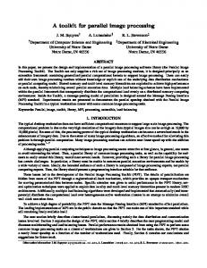
The methodology (fig.1) develops conceptual approach to software engineering [10] and some other approaches known as yet by the integrated set of object calculus models for problem domain (meta)data representation and manipulation. The models are based on a synthesis of typed O-calculus [1] and category theory, represented by category combinatory logic [2]. The system environment is modeled by a state-based abstract
machine in Cartesian closed categories [2]. Computation semantics are modeled in terms of variable domains [8]. Frame-based approach [6] is used to visually model the object behavior of heterogeneous weak-structured globally distributed problem domains. The major benefits of the suggested composite theoretical background are unified control of (meta)information within a single model framework, and adequate object-relational mapping for semi-structured, heterogeneous ERP systems in globally distributed environments. Definition and manipulation languages for data and metadata objects in globally distributed environments, which are based on relational algebra for ERP system data and object-oriented SQL extensions, can be represented as a specific (meta)data object model, extended by embedded scenario-activated scripts and stored procedure-based queries. UML-based objectrelational (meta)data transformation results in the architectural scheme of the ERP systems, represented by a set of model-and-CASE-driven UML diagrams and source code. Thus, ERP system development starts from problem domain conceptualization and ends by the implementation in terms of software module and interface code. Each of the development stages includes multiple levels, where statements are described in terms of a corresponding universe (world), embracing a domain of objects, environment, and formal languages for (meta)data definition and manipulation (fig.1). At the first stage of the methodology, the world is the problem domain specification in natural language terms, the data manipulation language is first order logic, and in case of a dynamic problem domain – higher order logic. The second stage is conceptualization, i.e. transformation from natural language problem domain representation to the formal model, and the universe is changed to conceptual model description of the problem domain [10]. Therewith, problem domain specification elements are mapped into concepts, and natural language relationships – into role relators. Logic of predicates is adequate for static problem domain conceptual models [10], while dynamics is formalized by higher order logic, based on semantic domains, and descriptors [8] are used in the data object definition language. To increase visibility without losing rigorousness, we are using semantic network data definition language with Roussopulos type of frames for visualization [7]. Thus, logical and casual relationships, integrity constraints and some other problem domain features are modeled. (Meta)data class hierarchy is modeled by partial order relationship (ISA). Due to frame algebra synthesis with finite sequence and category theories, formal software testing and verification of ERP systems and enterprise data warehouses becomes possible.
Figure 1. Complex software application development diagram
Dynamic (meta)data object behavior model is visualized by event frames. Frame algebra is used to model data object manipulation, it includes extensions for embedded functions and integrity constraints [7]. Problem domain conceptual model supported by the ConceptModeller tool [5], which is used for the third stage, the ‘lower’ CASE. The universe is changed for visual problem domain conceptual model representation in terms of frame hierarchy, the elements of which include concepts as nodes, relationships as arcs, and metadata as possible data object value ranges (e.g. quantifiers, etc.). ConceptModeller is aimed at frame-based automatic visual ERP system design, development and integration. The tool supports partial order-based frame hierarchy, basic frame elements (e.g., arcs, nodes, etc.) and various frame types (including event frames). ConceptModeller XML-based repository uniformly stores data and metadata (identifiers, integrity constraints, etc.). The data object manipulation language is based on frame algebra. During the fourth stage (intermediate CASE), the visual representation of problem domain conceptual model is automatically translated by ConceptModeller into UML standard specifications. At this stage, the
universe is a UML model as a family of interrelated diagrams (use-case, class, etc.). UML has been chosen for complex distributed problem domain modeling (including heterogeneous and weak-structured problem domains), since it is an international standard for (large-scale) ERP system engineering. Frame elements are translated into UML diagrams, while hierarchy and integrity constraints are maintained (UML representation is preferred for complex heterogeneous ERP systems). The OCL language is used to describe integrity constraints for complex problem domains, which is a part of UML standard. The rest ERP implementation stages, from ‘upper’ CASE to implementation (fig. 1), can be automated by traditional CASE tools.
4. ConceptModeller: the tool to integrate the methodology To provide an adequate automation level of iterative ERP system development, reverse engineering is implemented in ConceptModeller as a semi-automated backward translation from UML to the frame model representation [7]. According to the methodology, the integration algorithm for embedding new components
into the existing ERP system environment involves ConceptModeller as follows [11,12]: 1. Design problem domain conceptual model and data model for the new component using ConceptModeller; 2. Reverse engineer existing components (possibly to as low as the problem domain conceptual model and data model level) using CASE tools, and ConceptModeller; 3. Define semantically preferable entities/objects and relationships for the components of the integration area(s) using ConceptModeller; 4. Eliminate doubling and contradictory entities and relationships of the integration area(s), so that only semantically preferable ones remain in the resulting problem domain conceptual model and data model using ConceptModeller; 5. Component-wise development of the integrated ERP system using ConceptModeller, and CASE tools. The major benefits of ConceptModeller are: adequacy to problem domain and the data model; problem domain orientation (experts use familiar terms for objects and relationships); visualized software development; state-ofthe-art development standards support (UML, XML, etc.); interface bridges to industrially approved CASE tools (IBM Rational, Microsoft Visual Studio, etc.); and two-way ERP system development (including reverse engineering). Due to the above benefits, ConceptModeller can be easily used by a wide spectrum of problem domain experts, and it allows to construct models in nearly natural language terms.
To ergonomically visualize frames, the interface has been improved to match the most user-friendly and efficient vector graphic processing application standards, such as Adobe PhotoShop. An example of simple frame visualization in ConceptModeller is given in fig. 2. Moreover, it becomes possible to automatically translate the integrated ERP and complex data warehouse scheme into problem domain conceptual model at any development stage (problem domain modeling, CASEguided UML-based implementation, testing, maintenance, etc.). Thus, it becomes possible to formally verify and validate the software at various abstraction levels. Certain programming languages and techniques, such as SML.NET, can be used to accelerate the verification and validation processes. The conceptual approach to visual software development is based on Roussopulos frame notation [7]. ConceptModeller user interface for visual problemoriented (simple) frame development (fig. 2) is the basic way of (meta)data entry and correction. Note, that the interface contains visualization facilities for the major elements of (simple) frames, such as concepts, variables, and various types of role arcs (variable, constant, type, characteristic and event frame roles). In the above example, an event frame is visualized that describes a (simplified) business situation of complex web content publishing. As the example demonstrates, the event frame visualization is fully adequate to conventional mathematical formal representation.
Figure 2. ‘Publish’ event frame visualization in ConceptModeller and the frame fragment XML representation in the database
5. Frame-to-UML ConceptModeller
translation
in
The ConceptModeller tool includes event-oriented components that visualize frames, store their XML representations, translate them into UML code, and visualize it as UML diagrams. A generalized scheme of
problem domain conceptual model translation by ConceptModeller is given in fig. 3. The scheme contains forward and reverse enterprise software development directions (since ConceptModeller supports both of them). Frame-to-UML translation is done componentwise and element-wise. The translation is based on algorithms and data structures, described in more detail in [11]. The majority of frame types (including event frames as in fig. 2) allows transformation to standard UML diagrams (e.g., class diagrams), which unifies user interface. Therewith, the data format is based on certain metadata types (including cardinality, frame type and some other parameters), which is not visualized in the
interface, but which is used for ERP software system development both in forward (from frames to UML diagrams) and in reverse directions. The above ConceptModeller interface example can be interpreted as a primary report form. ConceptModeller features internal (system-level) report generation. The system reports contain a elaborate metadata, which is used to describe certain internal parameters of frames and UML diagrams (e.g., semantic roles for the arcs joining the concepts, etc.). Detailed description of the metadata structure is beyond the scope of the paper, more details are given in [11].
Figure 3. ConceptModeller translation scheme
ConceptModeller GUI elements are designed similarly to software imaging packages (particularly, Adobe Photoshop), so that they provide intuitive transparency for problem domain analysts, high ergonomics and efficiency level for complex system development and integration. GUI elements are stored and processed within a separate (meta)database. Data exchange with ERP and CASE applications is based on a unified technology of system resources. Resources are file structures that contain metadata descriptions in XML format. Double representation of frames as graphics and database structure elements requires multi-level data structure development for frame storage. The (meta) database should possess properties of completeness, extendibility for adding metadata, and flexible visual interpretation (including multiple instance support). Microsoft .NET framework has been chosen as the development platform to simplify the process of frame-to-UML translation. XML is a standard database format solution with convenient visualization. The XML database manipulation is based on XML Designer component of Microsoft Visual Studio 2008. The XML Designer is used for schema generation of template database defining frame elements. A brief XML code example (fig. 2) demonstrates description of MyVar frame variable with type Var and 100*50 pixel size in ConceptModeller GUI.
The major benefits of the ConceptModeller tool architecture and interface are problem-oriented IS development in nearly natural language terms, situationbased problem domain conceptual model visualization through the entire software lifecycle, intuitive transparency due to usage of an industry approved UML standard of (visual) ERP development/integration, and interface-level support of two-way software development (reverse engineering). Details of implementation mechanisms for software development with ConceptModeller, frame model translation into UML diagrams, and metadata storage are given in [11,12].
6. Implementation, conclusion and prospects ConceptModeller is implemented in C# language and contains over 5,000 lines of source code including eventdriven components for frame visualization, frame translation to UML code and for the visual representation of the resulting code. Microsoft Visual Studio .NET has been chosen as the implementation platform. The platform choice criteria included Internet orientation, programming language spectrum for heterogeneous (meta)data manipulation, heterogeneous (meta)database integration degree, semi-structured (meta)data storage
capacity, UML standard meeting, and technical support quality level. To provide efficient ERP development and integration in heterogeneous, globally distributed environments, a problem-oriented visual ConceptModeller CASE tool has been implemented. The tool allows to eliminate the logical gaps in existing software development methodologies by bridging problem domain formal model and conventional CASE systems. The CASE tool as a part of the software development methodology has been approved by a number of successful implementations of ERP systems in ITERA International Group of Companies with nearly 10,000 employees in 150 companies of 24 countries [13-16]. During the ERP development and integration, the problem domain specifications (in terms of semantic networks) have been transformed by ConceptModeller to UML diagrams, and, finally, into target ERP architecture and (meta)database schemes. The resulting Web pages have been published in ITERA Internet/Intranet portal (www.iteragroup.com) [14]. As a result of the implementation based on the proposed methodology, implementation terms and costs compared to commercial software available have been considerably reduced (by the average of 30% in case of heterogeneous environments). The implementation proved efficiency of the approach on the whole and its separate components (concepts, models, and CASE tools). The author is going to continue his studies of complex software development methodologies, supporting models and tools. A promising direction would be revising ConceptModeller on the basis of domain specific language (DSL) technology and the emerging UMLbased visualization capabilities of Microsoft Visual Studio.
References [1] Barendregt H.P. The lambda calculus (revised edition), Studies in Logic, 103, North Holland, Amsterdam, 1984 [2] Curry H.B., Feys R. Combinatory logic, Vol.1, North Holland, Amsterdam, 1958 [3] Forbus K., Birnbaum L., Wagner E. et al. Combining analogy, intelligent information retrieval, and knowledge integration for analysis: A preliminary report. In: 2005 International Conference on Intelligence Analysis, McLean, Virginia, USA, 2005 [4] Lenat D., Guha R.V. Building Large Knowledge-Based Systems: Representation and Inference in the Cyc Project. Addison-Wesley, 1990 [5] Masters J., Güngördü Z. Structured Knowledge Source Integration: A Progress Report. In: Integration of Knowledge Intensive Multiagent Systems, Cambridge, MA, USA, 2003
[6] Reed S., Lenat D. Mapping Ontologies into Cyc. In: AAAI 2002 Conference Workshop on Ontologies For The Semantic Web, Edmonton, Canada, 2002 [7] Roussopulos N.D. A semantic network model of databases. Toronto Univ., 1976 [8] Scott D.S. Lectures on a mathematical theory of computations. Oxford University Computing Laboratory Technical Monograph. PRG-19, 1981, 148 pp. [9] Witbrock M., Panton K., Reed S.L., et al. Automated OWL Annotation Assisted by a Large Knowledge Base. In: Workshop on Knowledge Markup and Semantic Annotation at the 3rd International Semantic Web Conference (ISWC 2004), Hiroshima, Japan, 2004, pp. 71-80 [10] Wolfengagen V.E. Event Driven Objects. Proc. CSIT'99. Moscow, Russia, 1999, p.p.88-96 [11] Zykov S.V. ConceptModeller: Implementing a Semantically-Based Toolkit for Enterprise Applications In: Proc. CSE-2006, Lviv, Ukraine, October 2006, Lviv Polytechnic National University Publishers, 2006, pp.23-26 [12] Zykov S.V. Enterprise Content Management: Bridging the Academia and Industry Gap In: Proc. i-Society 2007, Merrillville, Indiana, USA, Oct. 7-11, 2007, Vol.I, p.p.145-152 [13] Zykov S.V. Enterprise Content Management: Theory and Engineering for Entire Lifecycle Support. In: Proc. CSIT'2006, Vol.1, Ufa State Aviation Technical University, USATU Publishers, Karlsruhe, Germany, 2006, pp. 86-92 [14] Zykov S.V. Integrated Methodology for Internet-Based Enterprise Information Systems Development. In: Proc. WEBIST2005, Miami, FL, USA, May 2005, p.p.168-175 [15] Zykov S.V. An Integral Approach to Enterprise Content Management. In: Callaos N., Lesso W., Zinn C.D., Zmazek B. (Eds.), Proc. of 11th International World Multi-Conference on Systemics, Cybernetics and Informatics (WMSCI 2007), Orlando, FL, U.S.A., July 8-11, 2007, Vol. I, p.p. 212-216 [16] Zykov S.V. The Integrated Methodology for Enterprise Content Management. In: WMSCI 2009, July 10-13, 2009 – Orlando, FL, USA , p.p.259-264