Proceedings of the 57th Israel Annual Conference on Aerospace Sciences, Tel-Aviv & Haifa, Israel, March 15-16, 2017
WeL1T1.3
Conceptual Design, Initial Sizing and Sensitivity Analyses of a High Altitude Airship using revised Volumetric Drag Shaik Subhani1 Technion-Israel Institute of Technology, Haifa, 3200003, Israel Rajkumar S. Pant2 Indian Institute of Technology-Bombay, Mumbai, 400076, India This paper will describe a methodology that can arrive at the baseline specifications of conventional configuration of a stratospheric airship, given the performance and operational requirements like payload mass, payload power, mission speed, geographical location, and altitude of deployment. The empirical relation for coefficient of volumetric drag is not accurate for all the geometries of airship hull. The coefficient of volumetric drag is revised for Wang profile shape with a fixed fineness ratio of 3.87 based on the data available from flow filed simulations via commercial CFD package FLUENT. The flow field simulations are carried out for a range of Reynolds numbers between 107-109. Results obtained using this sizing methodology for some typical operating requirements for stratospheric airships will also be presented. The sensitivity of the airship size and all up weight to some key input parameters will also be brought out.
I. Introduction There is a global interest in design and development of High Altitude Airships [1], which can serve as a long endurance platform for deployment of equipment for several commercial and strategic applications e.g., next generation wireless broadband telecommunications [2], digital broadcasting [3], coastal surveillance [4], remote sensing and GPS augmented navigation systems [5], and space based applications [6]. These airships are designed to be able to maintain a quasi-stationary position at altitudes of around 20 km, where ambient winds are of low magnitude. Such airships function as lowaltitude satellites, but offer much shorter transmission distances and ranges with high resolution, and lesser signal propagation errors. They are much more economical compared to satellites, as they can be relocated or brought down and refurbished with latest equipment. Several researchers have proposed methodologies and approaches for conceptual design and sizing of high altitude airships [6-10]. The shape of the envelope is one of the most critical elements in the design of such systems, and envelope shape optimization is a key area of research in this field [11-14]. Concurrent subspace optimization techniques have also been applied to the conceptual design and sizing of airships [15]. Due to long endurance missions, and the high altitude of operation, conventional propulsion systems may not be suitable for high altitude airships. Instead, it is proposed 1 2
Graduate Student, Faculty of Aerospace Engineering,
[email protected] Professor, Department of Aerospace Engineering,
[email protected]
Proceedings of the 57th Israel Annual Conference on Aerospace Sciences, Tel-Aviv & Haifa, Israel, March 15-16, 2017
WeL1T1.3
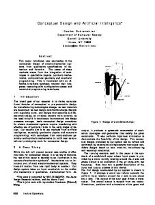
to mount Solar cells on the top of the envelope to meet the power requirements of the airship to maintain station, as well as that of the payload mounted onboard. The excess power generated by these solar cells during the daytime will be utilized to charge the onboard batteries, which then meet the needs during night-time, or occasions when the solar power is insufficient. This paper presents a methodology for sizing of high altitude airship given the user specified requirements like payload weight and power etc. II. Methodology for Initial Sizing The general layout of the methodology is depicted in Fig. 1. Once the operational requirements are specified, the methodology estimates the geometrical dimensions and mass breakdown of the stratospheric airship, meeting the requirement of payload weight and power. The power requirement is fulfilled in daytime by part of direct energy output from the solar cells to minimize the conversion losses with the geometric coverage ratio of 45%, whereas the remaining part of the energy output is used to charge the RFC (Regenerative fuel Cells) storage for night hours or crisis time. The calculation for energy is made for worst winter condition to avoid shortfalls for long term.
START Design Conditions Change Length
Airship Length Fineness ratio Location Volume
Date
Surface Area of Airship
Structural Wt.
Area of Solar cells Irradiance
Wt. of Solar cells
Wind Speed
Temp.
Power O/P Charging Power
Thrust req.
Drag
Densities Wt. of RFC
Power req. by Propulsion
Buoyancy Wt. of Propulsion
No
No Payload Ckeck
Total Power req. Power Check Yes
Yes STOP/Output
Figure 1. Methodology for Initial Sizing
Pressure
Proceedings of the 57th Israel Annual Conference on Aerospace Sciences, Tel-Aviv & Haifa, Israel, March 15-16, 2017
WeL1T1.3
A. Airship Envelope Profile Shape Exploring the possibility of better shapes in view of multidisciplinary optimization, a shape generation algorithm was proposed by Wang et al.[12,13]. The geometry of the airship envelope is governed by four shape parameters a, b, c, d and length l. The reference shape of the airship geometry is shown in Fig. 2. The equation of the airship body is expressed as, 64(y2+z2) = a (l-x) ( bx-l√𝑐+√𝑐𝑙 2 − 𝑑𝑙𝑥)
(1)
Since the complete airship body is obtained by revolving the 2D shape by 360 o about the X-axis, the 2D shape equation can be transformed as follows:
y=
√𝑎 (𝑙−𝑥) ( 𝑏𝑥−𝑙√𝑐+√𝑐𝑙2 −𝑑𝑙𝑥) 8
(2)
Figure 2. Wang Reference Shape
B. Model of Volumetric Drag Coefficient Cheeseman [16] has suggested an empirical relation for estimation of volumetric drag of an airship envelope, in terms of its fineness ratio and flow Reynolds Number. In general, the coefficient of volumetric drag for airship envelopes is determined using Eq. (3).
CDV =
1 𝑙 3 𝐷
𝐷 1.2 𝐷 2.7 +1.032( ) 𝑙 𝑙 1 𝑅𝑒 6
0.172( ) +0.252( )
Where, l is the envelope length D is the maximum diameter
(3)
Proceedings of the 57th Israel Annual Conference on Aerospace Sciences, Tel-Aviv & Haifa, Israel, March 15-16, 2017
WeL1T1.3
However, this relation is not at all sensitive to the profile shapes of the envelope, and errors in excess of 30% are reported. Kale et.al [17] has revised this relation of volumetric drag coefficient for envelope profile shapes which are an outcome of a shape generation algorithm based on the results obtained from flow field simulations using a commercial CFD package FLUENT. Spalart Allmaras turbulence model was used in the flow filed simulations. The relation for volumetric drag given in Eq. (3) is not accurate for Wang profile shape and this need to be revised. The relation for volumetric drag has been revised for Wang profile shape of an envelope with a fixed fineness ratio of 3.87, based on the results obtained from flow field simulations using commercial CFD package FLUENT. The simulations are performed for a range of operating Reynolds numbers between 10 7-109. Reynolds stress turbulence model is employed in the simulations to incorporate the effects of transition and turbulence at high Reynolds flows.
CDV =
CDV =
1 𝑙 3 𝐷
𝐷 1.2 𝐷 2.7 +1.032( ) 𝑙 𝑙 1 6 𝑅𝑒
0.172( ) +0.252( )
1 𝑙 3 𝐷
𝐷 1.2 𝐷 2.7 +1.032( ) 𝑙 𝑙 1 6 𝑅𝑒
0.172( ) +0.252( )
+ 0.0442 Re-0.033
; 107 ≤ Re ≤ 108
(4)
+ 0.0348 Re-0.02
; 108 < Re ≤ 109
(5)
C. Model of Surface Area and Volume of the Envelope The surface area of the envelope ‘Ae’ can be calculated using Eq. (6) as: 𝑙
2
Ae = 2π∫0 𝑦√1 + (𝑑𝑦) 𝑑𝑥 𝑑𝑥
(6)
The volume of the envelope ʻVʼ can be calculated using Eq. (7) as: 𝑙
V = π∫0 𝑦 2 𝑑𝑥
(7)
D. Model of Mass of the Propulsion System The mass of the propulsion system mass is calculated using Eq. (8) as: mthrust = Pthrust/wthrust
(8)
Whereas, Pthrust is the thrust power required wthrust is the power density of propulsion system Pthrust = Dtotal ν/ƞpƞg
(9)
Proceedings of the 57th Israel Annual Conference on Aerospace Sciences, Tel-Aviv & Haifa, Israel, March 15-16, 2017
WeL1T1.3
Whereas, Dtotal is the total drag of the airship ƞp is the propulsive efficiency ƞg is the gear transmission efficiency Dtotal = γ ρav2CDVV2/3/2
(10)
Where, γ is the interference factor to incorporate the drag on the control surfaces. E. Energy System Mass Calculation Solar array mass (marray) and Regenerative fuel cell mass, together constitute the energy system mass (menergy). The mass of the solar array can be calculated using Eq. (11) as: marray = 1.3RscS ρarray
(11)
Where, factor 1.3 is considered to incorporate the mass of the grid network and other auxiliary components. Rsc is the solar array coverage ratio S is the surface area of the envelope ρarray is the mass density of the solar array. The mass of the RFC storage unit can be calculated using Eq. (12) as: mstore = Ptotal t/ ƞRF ρRF
(12)
Whereas, Ptotal = Pthrust + Ppayload + Pctrls ƞRF is the efficiency of the regenerative fuel cells ρRF is the power storage density of the RFC unit F. Structure Mass Calculation Total mass of Structural subsystem (mstructure) is calculated using Eq. (13) as: mstructure = mgas+ mhull + mfin + mc
(13)
Where, mgas, mhull, mfin and mc are the masses of LTA gas, hull, fin and other component respectively, and are calculated using Eq. (14), Eq. (15), Eq. (16) as: 𝑀𝑊𝑔𝑎𝑠
mgas = ρa 𝑀𝑊𝑎𝑖𝑟 Vhull
(14)
Where, MWgas and MWair are the molecular weights of LTA gas and ambient air respectively. mhull = 1.2ρfabricShull
(15)
mfin = 1.2ρfabricSfin
(16)
Proceedings of the 57th Israel Annual Conference on Aerospace Sciences, Tel-Aviv & Haifa, Israel, March 15-16, 2017
WeL1T1.3
20% of hull and fin mass are increased to incorporate the extra weight during the manufacturing of the airship. ρfabric is density of fabric used for envelope. Sfin is the surface area of fin, which can be obtained by the following relation: Sfin/Vhull = 0.0121 m2/m3
(17)
Mass of other components like ballonets can be taken as the 25% of total mass of hull, fin, energy and thrust subsystems. mc = 0.25(mhull + mfin + menergy + mthrust)
(18)
Total mass (mtotal) is calculated as: mtotal = mthrust + mstructure + menergy + mpayload
(19)
III. Input and Output Parameters of the Methodology The operating requirements and values of some design parameters that are assumed to be constants are listed in Table 1 and Table 2 respectively. Table 1. Operating Requirements
Input Parameters Payload mass (kg) Payload Power (kW) Control Systems Power (kW) Floating Height (m) Mission Speed (m/s) Average Irradiance (W/m2) Discharge Time (hr) Off Standard temperature (K)
Value 1000 10 1 20,000 20 444 14 +20
Table 2. Design Constants
Parameters Fineness Ratio Interference factor Geometric Coverage ratio Envelope mass/area ratio (g/m2) Solar cells mass/area ratio (g/m2) Solar cells efficiency (%) RFC storage energy/mass ratio (Wh/kg) RFC efficiency (%) Propeller power/mass ratio (W/kg) Propeller efficiency (%) Gear transmission efficiency (%)
Value 3.87 2 0.45 120 150 9 450 95 225 90 95
Proceedings of the 57th Israel Annual Conference on Aerospace Sciences, Tel-Aviv & Haifa, Israel, March 15-16, 2017
WeL1T1.3
The Wang reference shape is digitized and the appropriate values of the shape coefficients are obtained by Newton's least squared method, in which the sum of the squared residuals is minimized. The residuals are obtained by the difference between the ordinate of the reference shape (obtained by digitizing the Wang shape) and their predicted values using the equation of the geometry. The values of the shape parameters are validated by comparing the envelope surface area and envelope volume with that of the reference shape of length of 194 meters listed in [12]. The initial values of the shape parameters are a = 7.447, b = 2.072, c = 9.010 and d = 7.981. The values of the key output parameters obtained by this methodology are listed in Table 3. The results of system mass breakdown are listed in Table 4. Helium is used as the LTA gas in arriving the baseline design parameters listed in Table 3 and 4. Table 3. Key Output Parameters
Output Parameter Envelope Volume (m3) Envelope Surface Area (m2) Envelope Length (m) Envelope Max. Diameter (m) Surface Area of the Solar Cells(m2) Thrust Required(Drag) N Thrust Power Required(kW) Total Power Required (kW)
Value 226880 22309.29 195.8 50.59 10039.2 5682.5 132.9 143.9
Table 4. System Mass Breakdown (kg)
System Total Structural Mass Propulsion System Mass Solar Array Mass RFC Storage Unit Total
Value 9110.45 590.78 1957.7 4713.3 16372.23
It can be noticed that, almost more than 50% of the total weight of the airship is due to its structure. Hence a shape which have better surface area/volume ratio can be chosen to minimize the structural weight and hence improve the payload capability of the airship.
Proceedings of the 57th Israel Annual Conference on Aerospace Sciences, Tel-Aviv & Haifa, Israel, March 15-16, 2017
WeL1T1.3
IV. Sensitivity Analyses The sensitivity of some of the important design parameters and operating conditions on the conceptual design of the airship are brought out. The detailed graphs indicating these variations are shown in this section. G. Effect on envelope volume with wind speed The envelope volume increases exponentially with wind speed, as can be seen in Fig. 3. It can be seen that, volume of the envelope with hydrogen as LTA gas is less in comparison with helium. But, it is not safe to use hydrogen as the LTA gas due to its chemically reactive and highly inflammable nature.
Envelope Volume (Cu. m)
1800000 1600000 1400000 1200000 1000000
Helium
800000
Hydrogen
600000 400000 200000 0 0
10
20
30
Wind Speed (m/s)
40
50
Figure 3. Envelope volume for 3.87 fineness ratio and various design speeds for 1000 kg payload
H. Effect on envelope length with wind speed
Length of the Airship (m)
400 350 300 250 200
Helium
150
Hydrogen
100 50 0 0
10
20
30
40
50
Wind Speed (m/s) Figure 4. Envelope length for 3.87 fineness ratio and various design speeds (for 1000 kg payload)
Proceedings of the 57th Israel Annual Conference on Aerospace Sciences, Tel-Aviv & Haifa, Israel, March 15-16, 2017
WeL1T1.3
The envelope length increases exponentially with wind speed, as can be seen in Fig. 4. It can be seen that, length of the airship envelope with hydrogen as LTA gas is less in comparison with helium. I. Effect of area density of envelope on airship length
Length of the Airship (m)
Figure 5 shows the varaiation of airship length with area density of the fabric. A linear relation is observed. 250 200 150 100 50 0 100
120
140
160
180
Area Density of Envelope Fabric (gsm)
200
220
Figure 5. Effect of area density of envelope on airship length
J. Effect of area density of solar cells on airship length Figure 6 shows the variation of airship length with area density of solar cells and linear variation is noticed. 205
Length of the Airship (m)
200 195 190 185 180 175 75
95
115
135
155
175
Area Density of Solar Cells (gsm) Figure 6. Effect of area density of solar cell on airship length
195
215
Proceedings of the 57th Israel Annual Conference on Aerospace Sciences, Tel-Aviv & Haifa, Israel, March 15-16, 2017
WeL1T1.3
K. Effect of efficiency of Regenerative Fuel Cell on envelope length Figure 7 shows the variation of envelope length with the efficiency of the regenerative fuel cell. Airship length decreases almost linearly in inverse proportion to the efficiency of the fuel cell. 450
Length of the Airship (m)
400 350 300 250 200 150
100 50 0 0
20
40
60
80
100
Efficiency of the Regenerative Fuel Cell (%) Figure 7. Effect of efficiency of fuel cell on airship length
L. Effect of length of airship on its Buoyancy and Weight
Buoyancy and Weight of the Airship (kg)
350000 300000 250000 200000
Buoyancy
150000
Weight of the Airship
100000 50000 0 0
100
200
300
400
500
600
Length of the Airship (m) Figure 8. Variations pattern of buoyancy and weight of the airship with length
Figure 8 shows the variations of the buoyancy and weight of the airship with length. For envelope length less than 196 meters, the weight of the airship is more than buoyancy.
Proceedings of the 57th Israel Annual Conference on Aerospace Sciences, Tel-Aviv & Haifa, Israel, March 15-16, 2017
WeL1T1.3
The rate of increment in buoyancy is much higher than that of weight, since the major constituent is weight defined by surface area, whereas the buoyancy is directly proportional to volume of the airship. The rapid improvement is observed in the payload capacity with the increase in length of airship, in line with the square-cube law. On increasing the size/length of the airship, a much higher payload capacity is observed but, handling and deployment of such giant sizes can become a major issue. M. Effect of wind speed on Thrust required (Drag) Figure 9 shows the variations in drag with size of the airship for different wind speeds. The nature of variation of drag with the length of the airship is nearly parabolic. However, the rate of variation is observed to be higher as we go on increasing the wind speed as, drag is proportional to the square of the wind speed. Hence, the size of the airship varies for same requirements of payload weight and power with different operating speeds (wind speeds). This is one of the reasons to maintain low floating altitudes (20-25 km) to observe minimum wind speeds. 30000 25000
Drag (N)
20000
10 m/s 15 m/s
15000
20 m/s 25 m/s
10000
30 m/s 35 m/s
5000
40 m/s
0 0
100
200
300
400
500
600
Length of the Airship (m) Figure 9. Effect of wind speed on thrust required for airship
N. Effect of payload on size (volume) of the airship The variation of volume of the airship with payload is shown in Fig. 10. Approximately a linear relationship between volume and the payload capacity of the airship is observed. An eight-fold increase in payload capacity is obtained by doubling the volume of the airship.
Volume of the Airship (Cu. m)
Proceedings of the 57th Israel Annual Conference on Aerospace Sciences, Tel-Aviv & Haifa, Israel, March 15-16, 2017
WeL1T1.3
500000 450000 400000 350000 300000 250000 200000
150000 100000 50000 0 0
1000
2000
3000
4000
5000
6000
7000
8000
9000
Payload (kg) Figure 10. Effect of payload on required volume of the airship
O. Effect of Altitude of station-keeping It is very well known that, atmosphere density decreases with altitude, which results in decrease in buoyancy of an airship. The payload capability of an airship decreases with altitude. This is shown in Fig. 11.
Buoyancy and Weight of the Airship (kg)
350000 300000 250000 200000
Weight of the Airship
150000
Buoyancy at H=20km
100000
Buoyancy at H=22km Buoyancy at H=24km
50000 0 0
100
200
300
400
500
600
Length of the Airship (m) Figure 11. Variations in length of the airship with altitude of station-keeping
P. Effect of Helium Purity on length of the airship Atmosphere may enter the helium chamber of the airship through small holes in the envelope thereby affecting the purity of the helium gas. The purity of the LTA gas decreases with duration of station-keeping of the airship. Fig. 12 shows the effect of the
Proceedings of the 57th Israel Annual Conference on Aerospace Sciences, Tel-Aviv & Haifa, Israel, March 15-16, 2017
WeL1T1.3
purity of the helium gas on the length of the airship. It can be noticed that, with decrease in the purity level of the helium gas, the length of the airship increases.
Length of the Airship (m)
205 204 203 202 201 200 199 198 197 196 195 88
90
92
94
96
98
100
102
Purity of the Helium gas (%) Figure 12. Variations in length of the airship with helium purity level
The results of sensitivity analyses for Wang profile shape are in line with the work reported by Chen [9] and Alam [10] for NPL profile shape of the envelope hull. V. Conclusion A methodology for conceptual sizing of an HAA (High Altitude Airship) platform has been proposed, with much lesser number of assumptions compared to other such methodologies reported in literature. The efficacy of the methodology in arriving at the output parameters, and in carrying out sensitivity analyses of key parameters has been demonstrated. The empirical relation for determining the volumetric drag coefficient is revised for Wang profile shape of the airship envelope with a fixed fineness ratio of 3.87 using the data available from flow filed simulations. It is seen that there is a minimum required volume of stratospheric airship to overcome the specified power and payload requirements. Due to large dimensions, even a slight increase in the wind speed results in large increase in drag. The interdependency – sensitivity of the airship design with variations in operating and design parameters are studied.
References [1] Epley, L. E., “Stratospheric Aircraft, Blimps, Balloons and Long Endurance Vehicles”, Chapter 5, Future Aeronautical and Space Systems, Eds. Noor, A. K. and Venneri, S. L., Progress in Astronautics and Aeronautics, Vol. 172, American Institute of Aeronautics and Astronautics, 1997.
Proceedings of the 57th Israel Annual Conference on Aerospace Sciences, Tel-Aviv & Haifa, Israel, March 15-16, 2017
WeL1T1.3
[2] Tozer, T. C., and Grace, D., “High-altitude platforms for wireless communications”, Electronics and Communication Engineering Journal, vol. 13, pp. 127-137, 2001. [3] Grace, D., and Mohorcic, M., “Broadband Communications via High-Altitude Platforms”, United Kingdom: John Wiley and Sons, Ltd., ISBN: 978-0-470-69445-9, 2011. [4] Colozza, A, and Dolce, J. L. “High-altitude, long- endurance airships for coastal surveillance”, NASA Technical Report, NASA/TM-2005-213427(2005). [5] Tsujii, T., Rizos, C., Wang, J., Dai, L. and Roberts, C., “A Navigation/Positioning Service Based on Pseudolites Installed on Stratospheric Airships”, 5th International Symposium on Satellite Navigation Technology & Applications, Australia, 2001. [6] Subhani, S., Alam, M. I., Pant, R. S., “Sizing of Stratospheric Airships for Space Based Applicationsˮ, 2nd International Space Conference, India, January 2015. [7] Lobbia, M. A., and Gong, R. H., “A modular sizing model for high-altitude/longendurance airships”, Paper AIAA-2006-821, Proceedings of 44th AIAA Aerospace Sciences Meeting and Exhibit, 9-12 January, Reno, Nevada, USA. [8] Yu, D., Lv, X., “Configurations analysis for high-altitude/long-endurance airships”, Aircraft Engineering and Aerospace Technology, Vol. 82 Iss: 1, pp.48 – 59, 2010 [9] Chen, Q., Zhu, M., and Sun, K., “Analysis to Effects on Conceptual Parameters of Stratospheric Airship with Specified Factors”, Journal of Computers, 6(5):1055– 1062, 2010. [10] Alam, M. I., and Pant, R. S., “A Methodology for Sizing and Optimization of High Altitude Airship”, AIAA 2013-1363, Proceedings of AIAA 20th Lighter-ThanAir Systems Technology (LTA) Conference, Daytona Beach, FL, USA Mar. 25-28, 2013. [11] Zhang, X., and Zhang, A., “Shape Optimization of Airship based on Constrained Particle Swarm Optimization”, Journal of Information & Computational Science 10:18(2013) 5849-5857, December 10, 2013. [12] Wang, Q., Chen, J., Fu, G., Duan, D., Zhao, H., “A methodology for optimisation design and analysis of stratosphere airship”. Aeronautical Journal, 113(1146), 533540, 2009. [13] Wang, Q., Chen, J., Fu, G., and Duan, D., “An Approach for Shape Optimization of Stratosphere Airships based on Multidisciplinary Design Optimization”, Journal of Zhejiang University SCIENCE A, 10(11):1609–1616, November 2009. [14] Alam, M. I., Subhani, S., and Pant, R. S., “Multidisciplinary Shape Optimization of Stratospheric Airshipsˮ, 6th International Conference on Theoretical, Applied, Computational and Experimental Mechanics, India, December 2014. [15] Liang, H., Zhu, M., and Guo, X., “Conceptual Design Optimization of High Altitude Airship in Concurrent Subspace Optimization”, 50th AIAA Aerospace Sciences Meeting, January, pages 1–17, Nashville, Tennessee, 2012. [16] Cheeseman, I., “Propulsion,” Airship Technology, Khoury, G. A., and Gillett, J. D., eds., Airship Technology, Cambridge University Press, Cambridge, USA, pp. 2533, 1999. [17] Kale, S. M., Joshi, P., Pant, R. S., “Generic Methodology for Determination of Drag Coefficient of an Aerostat envelope using CFD”, AIAA 16th Lighter-Than-Air Systems Technology Conference and Balloon Systems Conference, September 2005, Arlington, USA.